

Page 1
HP Networking 6600 Switch Series Technical Overview
v1.0
Table of contents
Table of contents . . . . . . . . . . . . . . . . . . . . . . . . . . . . . . . . . 1
Table of figures and tables . . . . . . . . . . . . . . . . . . . . . . . . . . 5
Executive summary. . . . . . . . . . . . . . . . . . . . . . . . . . . . . . . . 7
Introduction . . . . . . . . . . . . . . . . . . . . . . . . . . . . . . . . . . . . 7
HP ProCurve 6600 Switch Series . . . . . . . . . . . . . . . . . . . . 7
Audience . . . . . . . . . . . . . . . . . . . . . . . . . . . . . . . . . . . . . 7
Scope . . . . . . . . . . . . . . . . . . . . . . . . . . . . . . . . . . . . . . . 7
Product positioning . . . . . . . . . . . . . . . . . . . . . . . . . . . . . . . 8
Overview . . . . . . . . . . . . . . . . . . . . . . . . . . . . . . . . . . . . . 8
Data center use models . . . . . . . . . . . . . . . . . . . . . . . . . . . 8
6600 series system overview . . . . . . . . . . . . . . . . . . . . . . . 10
Chassis layout . . . . . . . . . . . . . . . . . . . . . . . . . . . . . . . . 10
System elements . . . . . . . . . . . . . . . . . . . . . . . . . . . . . . . 10
HP ProCurve 6600 Switch Power Supply (J9269A) . . . . . . 10
HP ProCurve 6600 Switch Fan Tray (J9271A) . . . . . . . . . . .11
6600 LEDs . . . . . . . . . . . . . . . . . . . . . . . . . . . . . . . . . 13
Processor . . . . . . . . . . . . . . . . . . . . . . . . . . . . . . . . . . . 14
Memory . . . . . . . . . . . . . . . . . . . . . . . . . . . . . . . . . . . 14
Page 2

Console port . . . . . . . . . . . . . . . . . . . . . . . . . . . . . . . . 15
Ethernet out-of-band management (OOBM) port . . . . . . . . 15
Auxiliary (USB) port. . . . . . . . . . . . . . . . . . . . . . . . . . . . 15
6600 series system architecture . . . . . . . . . . . . . . . . . . . . . . 15
HP ProCurve 6600-24G Switch (J9263A) . . . . . . . . . . . . . . 15
Description . . . . . . . . . . . . . . . . . . . . . . . . . . . . . . . . . 16
Ports . . . . . . . . . . . . . . . . . . . . . . . . . . . . . . . . . . . . . . 16
Management connectivity . . . . . . . . . . . . . . . . . . . . . . . 16
HP ProCurve 6600-24G-4XG Switch (J9264A) . . . . . . . . . . 16
Description . . . . . . . . . . . . . . . . . . . . . . . . . . . . . . . . . 16
Ports . . . . . . . . . . . . . . . . . . . . . . . . . . . . . . . . . . . . . . 17
Management connectivity . . . . . . . . . . . . . . . . . . . . . . . 17
HP ProCurve 6600-48G Switch (J9451A) . . . . . . . . . . . . . . 18
Description . . . . . . . . . . . . . . . . . . . . . . . . . . . . . . . . . 18
Ports . . . . . . . . . . . . . . . . . . . . . . . . . . . . . . . . . . . . . . 18
Management connectivity . . . . . . . . . . . . . . . . . . . . . . . 18
HP ProCurve 6600-48G-4XG Switch (J9452A) . . . . . . . . . . 19
Description . . . . . . . . . . . . . . . . . . . . . . . . . . . . . . . . . 19
Ports . . . . . . . . . . . . . . . . . . . . . . . . . . . . . . . . . . . . . . 20
Management connectivity . . . . . . . . . . . . . . . . . . . . . . . 20
HP ProCurve 6600-24XG Switch (J9265A) . . . . . . . . . . . . . 21
Description . . . . . . . . . . . . . . . . . . . . . . . . . . . . . . . . . 21
Enhanced packet buffers . . . . . . . . . . . . . . . . . . . . . . . . 22
Ports . . . . . . . . . . . . . . . . . . . . . . . . . . . . . . . . . . . . . . 22
Management connectivity . . . . . . . . . . . . . . . . . . . . . . . 22
ProVision ASIC architecture . . . . . . . . . . . . . . . . . . . . . . . . . 22
Inside the ProVision ASIC architecture . . . . . . . . . . . . . . . . . 22
Classification and lookup . . . . . . . . . . . . . . . . . . . . . . . . 22
Policy Enforcement Engine . . . . . . . . . . . . . . . . . . . . . . . 23
Network switch engine programmability . . . . . . . . . . . . . 23
Fabric interfaces . . . . . . . . . . . . . . . . . . . . . . . . . . . . . . 23
ProVision ASIC CPU . . . . . . . . . . . . . . . . . . . . . . . . . . . 23
Fabric ASIC . . . . . . . . . . . . . . . . . . . . . . . . . . . . . . . . . 24
Management subsystem . . . . . . . . . . . . . . . . . . . . . . . . . 24
ProVision hardware resiliency . . . . . . . . . . . . . . . . . . . . . 24
6600 series accessories . . . . . . . . . . . . . . . . . . . . . . . . . . . 24
HP ProCurve 6600 Switch Premium License (J9305A) . . . . . . 24
Page 3

HP ProCurve 6600 Switch Power Supply (J9269A) . . . . . . . . 24
HP ProCurve 6600 Switch Fan Tray (J9271A) . . . . . . . . . . . 25
Rack mounting options . . . . . . . . . . . . . . . . . . . . . . . . . . . 25
2-post telco racks . . . . . . . . . . . . . . . . . . . . . . . . . . . . . 25
4-post racks: HP ProCurve 6600 Series Rack Mount Kit
(J9469A) . . . . . . . . . . . . . . . . . . . . . . . . . . . . . . . . . . . 25
HP 10000 series server racks: HP 10000 Series Rack
Mount Kit (5070-0145) for 6600 series . . . . . . . . . . . . . . 25
6600 series air plenums. . . . . . . . . . . . . . . . . . . . . . . . . . 26
HP ProCurve 6600 Series Air Plenum Kit (J9480A) . . . . . . 26
HP ProCurve 6600-24G/24G-4XG Air Plenum (J9481A) . . . 26
Transceivers and direct attach cables . . . . . . . . . . . . . . . . . 27
1-Gb SFP (mini-GBIC) transceivers . . . . . . . . . . . . . . . . . . 27
10-Gb SFP+ transceivers . . . . . . . . . . . . . . . . . . . . . . . . 27
10-Gb SFP+ direct attach cables . . . . . . . . . . . . . . . . . . . 27
Overview of features and benefits . . . . . . . . . . . . . . . . . . . . 28
Feature set summary . . . . . . . . . . . . . . . . . . . . . . . . . . . . 30
Data center optimized . . . . . . . . . . . . . . . . . . . . . . . . . . 30
Management . . . . . . . . . . . . . . . . . . . . . . . . . . . . . . . . 30
Connectivity . . . . . . . . . . . . . . . . . . . . . . . . . . . . . . . . . 30
Performance . . . . . . . . . . . . . . . . . . . . . . . . . . . . . . . . 31
Resiliency and high availability . . . . . . . . . . . . . . . . . . . . 31
Layer 2 switching . . . . . . . . . . . . . . . . . . . . . . . . . . . . . 31
Layer 3 services . . . . . . . . . . . . . . . . . . . . . . . . . . . . . . 31
Layer 3 routing . . . . . . . . . . . . . . . . . . . . . . . . . . . . . . . 31
Security . . . . . . . . . . . . . . . . . . . . . . . . . . . . . . . . . . . . 31
Multicast support . . . . . . . . . . . . . . . . . . . . . . . . . . . . . 32
Quality of Service (QoS) . . . . . . . . . . . . . . . . . . . . . . . . 32
Warranty and support . . . . . . . . . . . . . . . . . . . . . . . . . . 33
Standards and protocols . . . . . . . . . . . . . . . . . . . . . . . . . 33
Capacity, performance, and features . . . . . . . . . . . . . . . . . . 33
6600 series comparison . . . . . . . . . . . . . . . . . . . . . . . . . 33
Routing and forwarding tables . . . . . . . . . . . . . . . . . . . . 34
Optimizing the 10-GbE port configuration for wire speed . . . 34
Throughput and latency performance data . . . . . . . . . . . . . 36
10-Gb performance traffic patterns . . . . . . . . . . . . . . . . . 36
Throughput test . . . . . . . . . . . . . . . . . . . . . . . . . . . . . . . 37
Page 4

Latency measurements . . . . . . . . . . . . . . . . . . . . . . . . . . 37
Power consumption measurements . . . . . . . . . . . . . . . . . . . 37
Power Save mode . . . . . . . . . . . . . . . . . . . . . . . . . . . . . 38
Services and support . . . . . . . . . . . . . . . . . . . . . . . . . . . . . 38
Lifetime warranty . . . . . . . . . . . . . . . . . . . . . . . . . . . . . . . 38
Free telephone support . . . . . . . . . . . . . . . . . . . . . . . . . . 38
Optional support services . . . . . . . . . . . . . . . . . . . . . . . . . 39
Appendix A: out-of-band management port . . . . . . . . . . . . . . 39
OOBM availability . . . . . . . . . . . . . . . . . . . . . . . . . . . . . 39
Applications supported with OOBM port . . . . . . . . . . . . . . 39
OOBM limitations . . . . . . . . . . . . . . . . . . . . . . . . . . . . . 40
Appendix B: Policy Enforcement Engine . . . . . . . . . . . . . . . . 40
Policy Enforcement Engine benefits . . . . . . . . . . . . . . . . . . . 40
Granular policy enforcement . . . . . . . . . . . . . . . . . . . . . 40
Hardware-based performance . . . . . . . . . . . . . . . . . . . . 40
Works with HP ProCurve Data Center Connection
Manager ONE . . . . . . . . . . . . . . . . . . . . . . . . . . . . . . . 40
Wire-speed performance for ACLs . . . . . . . . . . . . . . . . . . . 40
Appendix C: PIM-Sparse Mode . . . . . . . . . . . . . . . . . . . . . . 41
Appendix D: virus throttle security . . . . . . . . . . . . . . . . . . . . 42
Response options . . . . . . . . . . . . . . . . . . . . . . . . . . . . . . 43
Sensitivity . . . . . . . . . . . . . . . . . . . . . . . . . . . . . . . . . . . . 43
Connection-rate ACL . . . . . . . . . . . . . . . . . . . . . . . . . . . . 43
Appendix E: VRRP . . . . . . . . . . . . . . . . . . . . . . . . . . . . . . . 43
Appendix F: OSPF Equal Cost Multipath . . . . . . . . . . . . . . . . 44
Appendix G: troubleshooting . . . . . . . . . . . . . . . . . . . . . . . 45
LED status indicators for 6600 series . . . . . . . . . . . . . . . . . 45
Appendix H: links to other useful documents . . . . . . . . . . . . . 46
White papers . . . . . . . . . . . . . . . . . . . . . . . . . . . . . . . . . 46
Technical briefs . . . . . . . . . . . . . . . . . . . . . . . . . . . . . . . . 46
Documents related to HP ProCurve 6600 Switch Series and
the data center . . . . . . . . . . . . . . . . . . . . . . . . . . . . . . . . 46
Page 5

Table of figures and tables
Figure 1: Top-of-rack use model . . . . . . . . . . . . . . . . . . . . . 9
Figure 2: HP ProCurve 6600 Switch Series (power supply
side view) . . . . . . . . . . . . . . . . . . . . . . . . . . . . 10
Figure 3: HP ProCurve 6600 Switch Power Supply
(J9269A) . . . . . . . . . . . . . . . . . . . . . . . . . . . . . .11
Figure 4: Default airflow direction and connectivity side
view of the 6600-24XG switch . . . . . . . . . . . . . . 12
Figure 5: HP ProCurve 6600 Switch Fan Tray (J9271A) . . . . 12
Figure 6: Closeup view of the HP ProCurve 6600 Switch
Series LEDs . . . . . . . . . . . . . . . . . . . . . . . . . . . 14
Table 1: 6600 buffer memory configurations . . . . . . . . . . 14
Figure 7: HP ProCurve 6600-24G Switch—ProVision ASIC
architecture overview . . . . . . . . . . . . . . . . . . . . 15
Figure 8: HP ProCurve 6600-24G-4XG Switch—
ProVision ASIC architecture overview . . . . . . . . . . 16
Table 2: 6600-24G/24G-4XG switches vs. 2910al-24G
and 3500yl-24G switches . . . . . . . . . . . . . . . . . 17
Figure 9: HP ProCurve 6600-48G Switch—ProVision ASIC
architecture overview . . . . . . . . . . . . . . . . . . . . 18
Figure 10: HP ProCurve 6600-48G-4XG Switch—
ProVision ASIC architecture overview . . . . . . . . . . 19
Table 3: 6600-48G/48G-4XG switches vs. 2910al-48G
and 3500yl-48G switches . . . . . . . . . . . . . . . . . 20
Figure 11: Recommended trunking uplink configuration for
the 6600-48G-4XG switch . . . . . . . . . . . . . . . . . 21
Figure 12: HP ProCurve 6600-24XG Switch—ProVision
ASIC architecture overview . . . . . . . . . . . . . . . . 21
Table 4: 6600 series accessories . . . . . . . . . . . . . . . . . . 24
Figure 13: HP ProCurve 6600 Rack Mount Kit (J9469A) . . . . 25
Figure 14: HP 10000 Series Rack Mount Kit (5070-0145)
for 6600 series . . . . . . . . . . . . . . . . . . . . . . . . 25
Figure 15: HP ProCurve 6600 Series Air Plenum . . . . . . . . . 26
Figure 16: HP ProCurve 6600 Series Air Plenum Kit
(J9480A) . . . . . . . . . . . . . . . . . . . . . . . . . . . . . 26
Figure 17: HP ProCurve 6600-24G/24G-4XG Air Plenum
(J9481A) . . . . . . . . . . . . . . . . . . . . . . . . . . . . . 27
Page 6

Table 5: SFP+ vs. X2 optics . . . . . . . . . . . . . . . . . . . . . . 27
Table 6: Capacity, performance, and features
comparison of the 6600 series products . . . . . . . 33
Figure 18: 4-port 10-GbE blocks showing how ports are
grouped to a 14.4-Gbps channel . . . . . . . . . . . . 34
Figure 19: 10-GbE module architecture showing four
ports grouped to a 14.4-Gbps channel . . . . . . . . 34
Figure 20: Approach for providing 10 Gbps on a specific
port . . . . . . . . . . . . . . . . . . . . . . . . . . . . . . . . 35
Figure 21: Providing equally balanced bandwidth in a
VRRP environment . . . . . . . . . . . . . . . . . . . . . . . 35
Table 7: 6600 series throughput performance . . . . . . . . . . 36
Table 8: 6600 series power consumption measurements . . 37
Table 9: Expected energy savings from 6600 Switch
Power Save mode . . . . . . . . . . . . . . . . . . . . . . . 38
Figure A-1: Out-of-band management use model . . . . . . . . . . 39
Figure C-1: PIM: Shared Tree example topology . . . . . . . . . . 41
Figure D-1: Virus throttle example topology . . . . . . . . . . . . . . 42
Figure E-1: VRRP example topology . . . . . . . . . . . . . . . . . . 44
Figure F-1: OSPF ECMP example technology . . . . . . . . . . . . 44
Table G-1: LED status indicators for management/system
support module . . . . . . . . . . . . . . . . . . . . . . . . 45
Table G-2: LED status indicators for ProCurve 6600 Switch
Series Ethernet ports . . . . . . . . . . . . . . . . . . . . . 46
Page 7

Executive summary
HP networking has an extensive line of networking products built around the concept of the ProCurve Adaptive
Network vision that provides the security, mobility, and convergence capabilities businesses demand while
giving technology administrators the ability to adapt to the changing needs of their organizations and control
their infrastructure centrally.
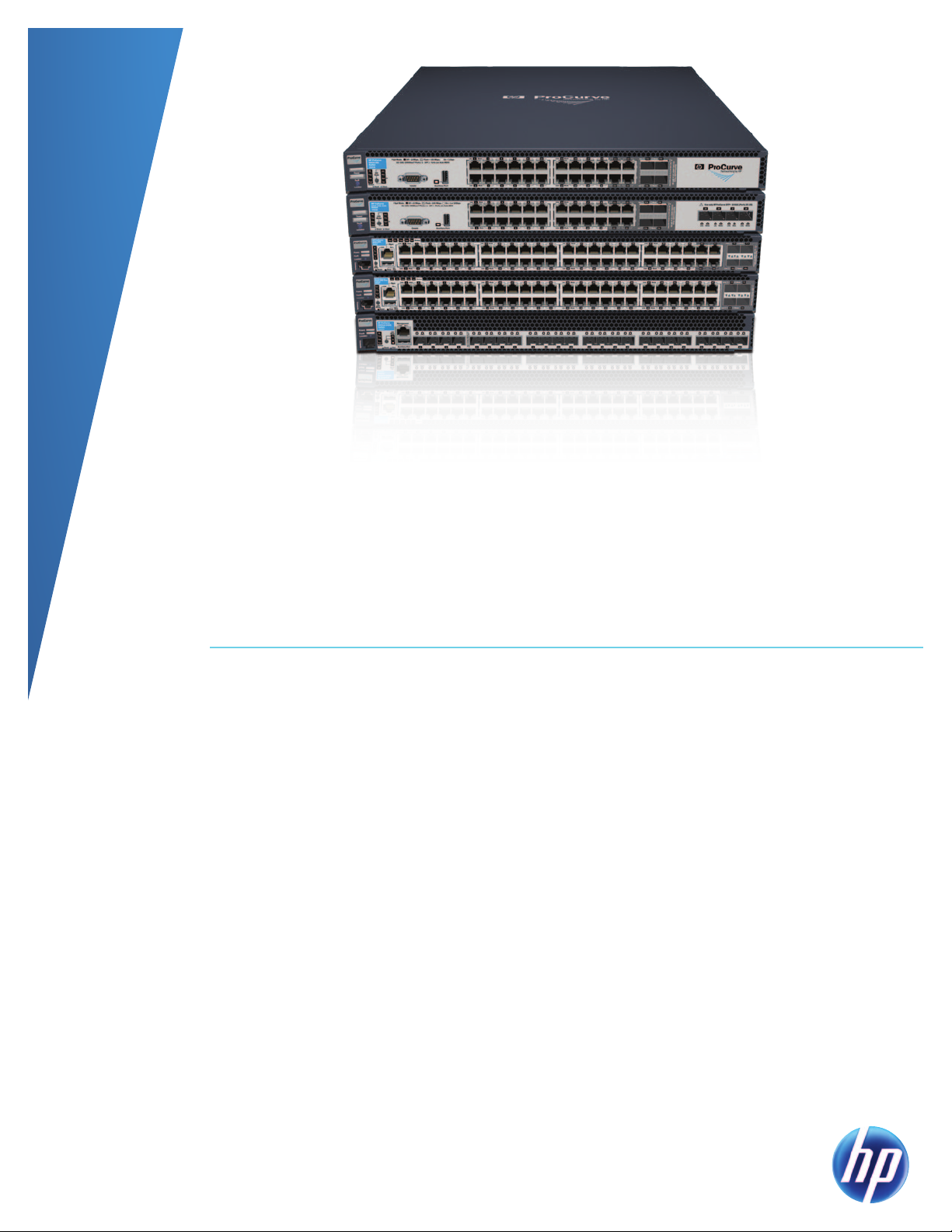
This guide describes the HP ProCurve 6600 Switch Series and how it builds upon the HP ProCurve Switch
8200zl, 5400zl, 6200yl, and 3500yl Series and the principles of the Adaptive Network by providing a
platform for delivering intelligence, performance, and affordability to the edge of the enterprise compute
network. Specifically, the HP ProCurve 6600 Switch Series enhances server edge connectivity in the data
center by delivering advanced Layer 2/3/4 capabilities that embody the Adaptive Network architecture, where
intelligence and decisions are made at the edge of the compute network and effective visibility, provisioning,
and automation is provided remotely. With Gigabit and 10-GbE SFP+ options, front-to-back (reversible)
airflow, redundant hot-swappable power supplies, and a hot-swappable fan tray, the 6600 switches offer high
availability, flexibility, and scalability for a highly virtualized server edge. The HP ProCurve 6600 Switch Series
is the industry’s first data center edge switch with a lifetime warranty and free software updates.
Introduction
HP ProCurve 6600 Switch Series
The HP ProCurve 6600 Switch Series enhances data center top-of-rack server connectivity and end-of-row
aggregation by offering Layer 2/3/4 functionality in 1-GbE copper and 10-GbE SFP+ options.
Audience
This guide is written primarily for technical evaluators and product reviewers of networking equipment and
solutions.
Scope
This guide provides detailed information about and specifications for the ProCurve 6600 Switch Series, with
the assumption that details about networking protocols can be referenced externally by those familiar with
general networking. Technologies that are relatively new will be covered in more detail than more familiar and
established technologies.
References to the ProCurve Switch 8200zl, 5400zl, 3500yl, and 6200yl Series are used as they relate to the
architecture and positioning of the 6600 switch series.
For more information regarding the complete line of HP networking products, please visit www.procurve.com.
7
Page 8

Product positioning
Overview
The intelligence, throughput, scalability, and physical connectivity options of the 6600 series make them
suitable for applications at the server edge or aggregation/distribution layer of a compute network. The 6600
switch series leverages the same ProVision ASIC and software found in the widely deployed 8200zl, 5400zl,
6200yl, and 3500yl products. Enhanced for the data center, the 6600 series provides front-to-back (reversible)
airflow, redundant hot-swappable power supplies, hot-swappable fan trays, expanded 10-Gb port buffering for
demanding high-availability applications.
The foundation for all of these switches is the purpose-built, programmable ProVision ASIC that allows the most
demanding networking features to be implemented in a scalable yet granular fashion. The 6600, 8200zl,
5400zl, 6200yl, and 3500yl series switches have been designed as a continuum of products that utilize a
common code image that enables consistency and scalability throughout the portfolio from data center core to
edge. The ProVision ASICs are aimed at achieving several technology and business imperatives:
•Providing superior feature capabilities and performance without sacrificing affordability
•Allowing sophisticated control features in both campus and data center networks
•Enabling programmatic capabilities to safeguard future needs and requirements
Data center use models
The HP ProCurve 6600 Switch Series includes one of the most advanced routing switches in the HP networking
product line. The 6600 switch series is targeted at both top-of-rack server access and end-of-row aggregation/
distribution for enterprise data centers and midmarket compute rooms. The 6600 series products ship standard
with the Intelligent Edge feature group, and offer an optional Premium License feature group that includes
advanced protocols such as Q-in-Q, PIM-SM, PIM-DM, OSPFv2, OSPFv3, and VRRP to support end-of-row use
models (RIP and static routing features are included in the standard Intelligent Edge feature group).
The 6600 series was specifically designed to support top-of-rack use models with the intent of supporting highly
virtualized server edge deployments for large Layer 2 scale-out systems. The advantages of top-of-rack use
models are effectively fourfold:
•Lower-cost design: Fixed configuration products offer significant per-port savings over modular-based
products. Additionally, top-of-rack products designed to support front-to-back airflow better support hot-aisle
and cold-aisle separation to reduce cooling expenses.
•Enhanced multi-tier network: Virtualized data centers require expansive Layer 2 footprints to allow for
adequate mobility between hypervisors and application scalability. The 6600 series supports 64K MAC
addresses for enhanced mobility and scale in the data center.
•Reduced cabling costs: With the eventual adoption of 10-Gb at the server edge, direct attach copper cables
from the server NIC to the top-of-rack switch significantly reduce the cost per connection versus expensive
fiber-optic connections.
•Easier edge network refresh: When networking becomes integrated in the rack with servers, technology
refreshes become easier to manage as the compute and networking building blocks are effectively deployed
in tandem.
8
Page 9
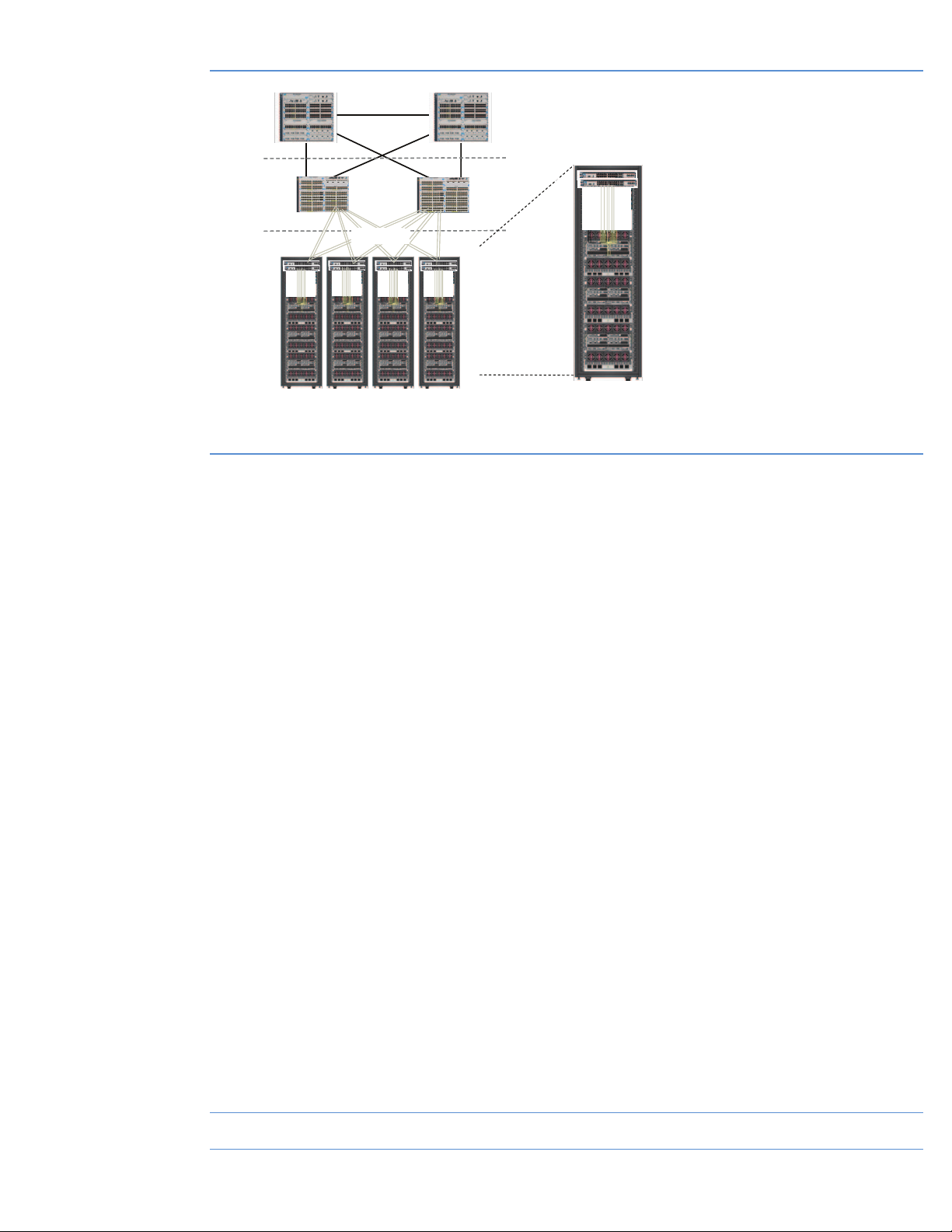
Figure 1 provides an example of a three-tiered networking model with top-of-rack networking components.
Data center
ProCurve edge switches deployed
Distribution
Server edge
All applications have standard server deployment
Figure 1: Top-of-rack use model
Server and network “packs”
network
Core
Standard
server edge
Standard
servers
as part of a standard solution
Top of rack: enables standard
server edge/edge networking racks
Top-of-rack advantages:
• Lower-cost design
• Enhanced multi-tier network designs
• Reduced cabling costs—copper
connections from server edge for 10-Gb
via direct attach
• Edge network can be refreshed more
easily and frequently without disturbing
distribution or core layers
–› Network can begin to match server
deployment requirements and processes
The 6600 series (specifically the 6600-24XG switch) is also ideal for end-of-row Layer 2 and Layer 3
aggregation, as the 6600-24XG switch provides the highest-density 10-Gb per rack unit in HP networking’s
product line. The advanced Layer 3 features provided in the Premium License make the 6600-24XG switch an
ideal candidate for aggregation and distribution in the data center. Key features of the ProCurve 6600 series to
support both top-of-rack and end-of-row use models include the following:
•Front-to-back (reversible) airflow—Enables highly virtualized compute environments where connectivity
ports face the hot aisle for use at top of rack. In addition, airflow can be reversed to support end-of-row
aggregation and distribution use models where users want data ports facing forward toward the cold aisle.
•Redundant, hot-swappable power supplies and fans—Power and fan resiliency as well as replaceable in
rack to increase availability.
•64K MAC address scalability—Supports best-in-class 64K MAC addresses to enable data center scale-outs of
highly virtualized server environments.
•Out-of-band management port—Isolated Ethernet management port provides robust access to the
management plane that is truly isolated from in-band data ports (available on 6600-48G, 6600-48G-4XG,
and 6600-24XG switches).
•sFlow for enhanced network visibility—Supports sFlow packet sampling to provide real-time visibility to
monitor traffic across all data ports at up to 10-Gb wire speed.
•Upgradability—Premium License option to support advanced Layer 3 functions most commonly needed for
end-of-row use models.
•Performance—High-capacity switch fabrics (from 48-Gbps to 322-Gbps backplane speed), bandwidth
shaping and control, QoS, and Layer 2 and Layer 3 jumbo frames.
•Security—ACLs (per-port or identity-driven), virus throttle, out-of-band Ethernet management, switch CPU
protection, detection of malicious attacks, DHCP protection, BPDU port protection, dynamic ARP protection,
dynamic IP lockdown, IP and MAC lockdown/lockout, IEEE 802.1X/Web/MAC user authentication, and
management access control (SSH, SSL, TACACS+, secure FTP).
•Resiliency—Redundant hot-swappable power supply options, hot-swappable fan tray, MSTP, switch meshing,
1
, OSPF-ECMP1.
VRRP
•IP Routing—RIPv1/v2, OSPFv2, OSPFv3, PIM-SM/DM, and static routes.
•Diagnostic—Remote intelligent mirroring, loopback interface, UDLD, and sFlow support.
1
Requires Premium Software License
9
Page 10
6600 series system overview
Internal power supply slots
The HP ProCurve 6600 Switch Series was designed to be co-located with data center servers for both top-ofrack edge access and end-of-row aggregation and distribution deployment models. To support high availability
in a 1U form factor, all 6600 series products allow for redundant hot-swappable power supply options, hotswappable fan tray, and front-to-back (reversible) airflow, along with out-of-band Ethernet management ports.
These are key capabilities that separate the 6600 series from other competitive products as well as other
products in the HP networking portfolio and position it well for data center top-of-rack and end-of-row designs.
To allow seamless core-to-edge deployment with HP networking products, the 6600 series shares the same
software and hardware building blocks as the 8200zl, 5400zl, 6200yl, and 3500yl products, thus reducing
complexity and operating expense.
The base configuration for the 6600 series as shipped from the factory includes the following:
•1 system fan tray (J9271A)
− The 6600 ships as a back-to-front direction for ports-rearward installation, but the fan tray is mechanically
reversible to support front-to-back (ports-forward) airflow when positioned as an end-of-row aggregation/
distribution switch.
•1 power supply (J9269A)
− The 6600 series has two power supply bays to support power redundancy.
− The power supplies are hot-swappable and allow for tool-less serviceability.
− The 6600 power supplies leverage the 1200 W ProLiant G6 “common-slot” supply to simplify sparing.
•Rack ears for mounting in a two-post telco rack
− For mounting in a four-post network/server rack, the 6600 rack mount kit (J9469A) that includes telescoping
rails is highly recommended.
•AC power cords
− The system ships with two AC power cords: one is the standard HP line cord using a C13 connector on the
power supply side and a country plug on the source end, while the other is a power distribution unit (PDU)
jumper cord with a C13 connector on the power supply side and a PDU plug on the source end. With either
option, the AC source is: 100 to 120 VAC/200 to 240 VAC; 7.5 A/3.75 A; 50/60 Hz.
Chassis layout
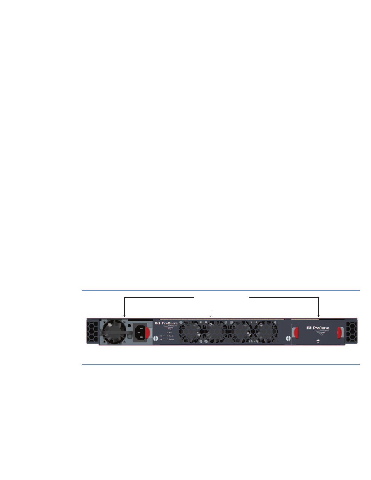
The 6600 switch series are high-density, 1U form factor switches. Figure 2 details the power supply side view
of the 6600 series products.
Fan tray
Figure 2: HP ProCurve 6600 Switch Series (power supply side view)
The 6600 fan tray and power supplies are all hot-swappable so that the switch does not have to be powered
off to remove these serviceable components.
System elements
HP ProCurve 6600 Switch Power Supply (J9269A)
Two power supplies need to be installed to take advantage of the power supply hot-swappable capabilities.
The power supply slots can accommodate the ProLiant G6 “common-slot” supplies. Currently, the 6600 series
10
Page 11
supports only the 1200 W AC supply, although the 6600 series is capable of supporting DC and other
common-slot supplies.
Two AC-to-12-V DC power supplies can be configured as 1+1 redundant supplies. The system is fully powered
with either power supply, and either power supply (but not both) can be removed and replaced while the
system is still racked, and the switch will continue to operate. Each power supply input is C14 with proper
safety ground.
110–120 VAC 200–240 VAC
Current < 7.5 A < 3.75 A
Output power > 548 W (> 45.7 A @ 12 VDC) > 548 W (> 45.7 A @ 12 VDC)
Efficiency (1 supply) < 677 W @ > 81% efficiency at full load < 677 W @ > 81% efficiency at full load
Efficiency (2 supplies) < 677 W @ > 75% efficiency at 50% load < 677 W @ > 75% efficiency at 50% load
Efficiency calculations include internal fans and line filter. The power supply size is 4.4 inch x 63 inch x 8 inch
3
) with an output power density of ~9.6 W/in3. The power supply ships with two W40S12BUA5-01
(57 in
40 mm x 40 mm x 28 mm (44,800 mm
3
) NIDEC fans or equivalent, producing 36 CFM (18 CFM each)
at .5 INWG using 13.2 W (6.6 W each).
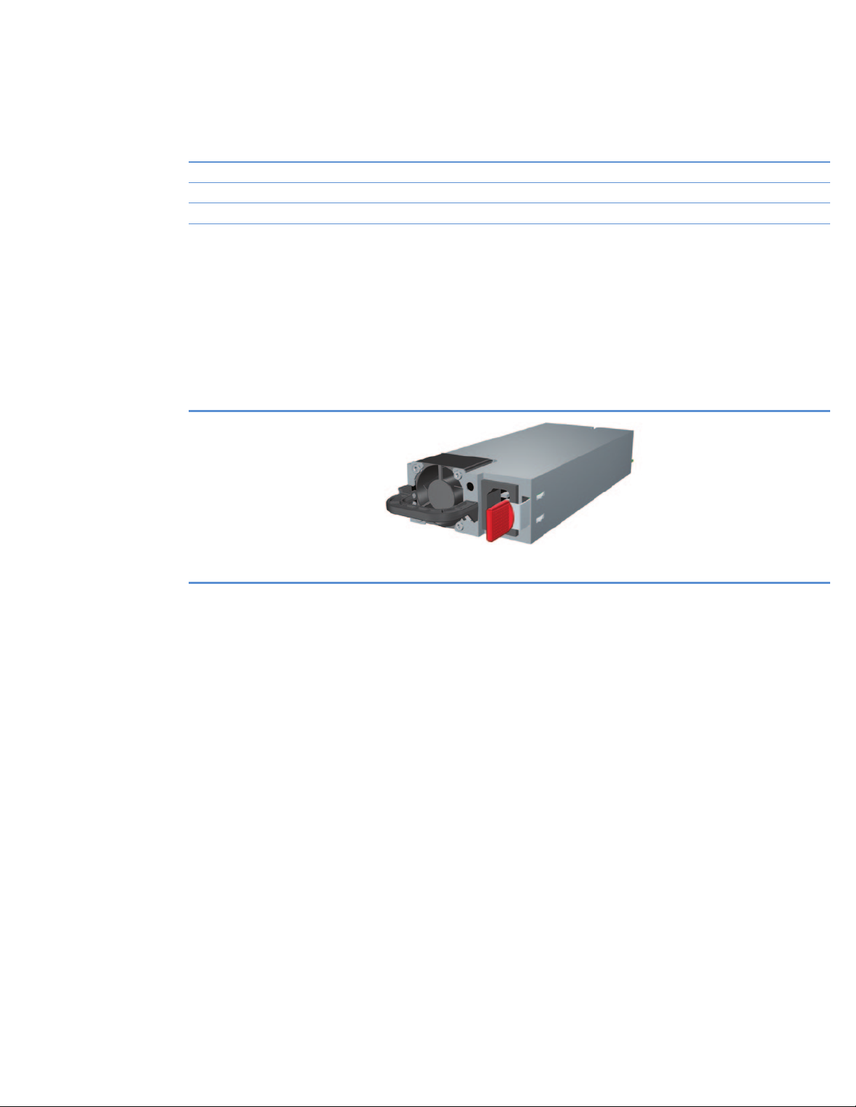
In terms of the power supply load-sharing algorithm when two supplies are installed, the power load is shared
equally across both supplies to improve longevity. All 6600 series products utilize the same power supply to
reduce sparing.
Figure 3: HP ProCurve 6600 Switch Power Supply (J9269A)
HP ProCurve 6600 Switch Fan Tray (J9271A)
The fan tray assembly contains the cooling fans for the interior of the 6600 chassis; the power supplies have
their own internal cooling fans. The 6600 fan tray consists of eight variable-speed fans, which offer N+N
redundancy. Thus, half of the eight fan rotors can fail and the system will maintain cooling capacity. The fan
speed is based on the sensed ambient temperature inside the chassis.
The default airflow configuration for the fan tray is power supply side to port side (front to back, also described
as power to port side). Figure 4 shows the default direction for the 6600 series products. The fan tray is
mechanically reversible, by first removing the fan tray and then loosening the four T10 torx screws on the
sides of the fan assembly. Reversing the fan tray should occur when the system has been powered off to allow
adequate time for replacement. A position sensor determines the configuration of the fan tray, which is then
reported through the CLI as to the direction of the airflow. There is a system configuration option (see section
titled “Monitoring airflow direction”) to report an error if a replacement fan is installed with the incorrect fan
orientation.
To support high-availability data center configurations, the fan tray can be replaced without system shutdown
if replacement occurs in under 3 minutes (the 6600 software monitors the time and takes required action to
protect the system). Because the fan tray can easily be replaced in less than 30 seconds, the 3-minute service
window provides adequate time to make a replacement, but users should replace the fans as quickly as
possible. Care must also be taken to install the replacement fan tray to help ensure that the airflow direction is
correct for the product’s deployment.
To reduce sparing requirements, all 6600 series products utilize the same fan tray.
11
Page 12
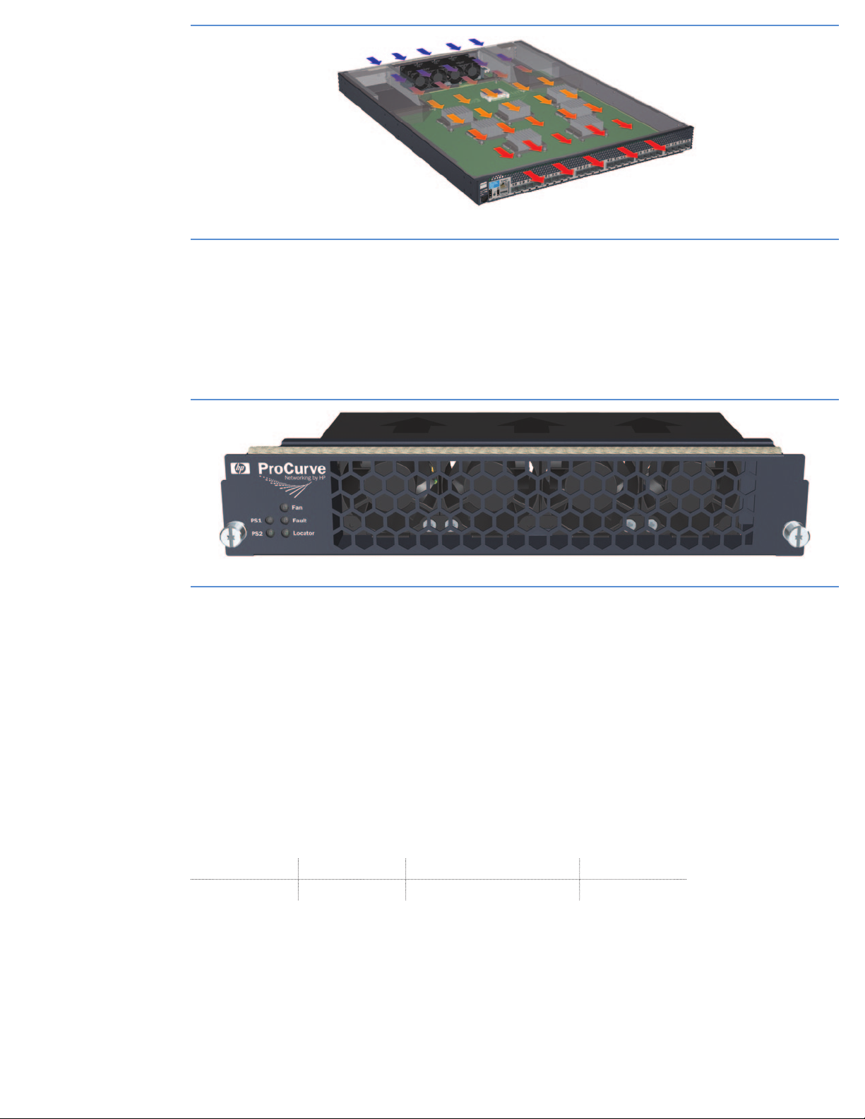
Figure 4: Default airflow direction and connectivity side view of the 6600-24XG switch
In the event of an individual fan failure, an SNMP trap and event log entry is generated. A system can typically
operate for quite a long time with a single fan failure (out of the eight), as the remaining fans can increase
speed to compensate for the loss of airflow.
The fan tray replicates the Power, Fan, Fault, and Locator LEDs found on the connectivity side of the 6600
switch. This is useful when attempting to locate a 6600 switch while servicing the product from either the hot- or
cold-aisle side of the equipment cabinets.
Figure 5: HP ProCurve 6600 Switch Fan Tray (J9271A)
Monitoring airflow direction
The “fan-pref-airflow-dir” CLI command registers the preferred airflow direction (front to back or back to front)
in the 6600 switch’s configuration file. Because the fan tray is mechanically reversible, it’s important for users
to monitor when fan hardware configuration does not match the desired configuration that is registered in the
configuration file. This notification is especially important when replacing a fan tray in a serviceable event. It
is important to note that the “fan-pref-airflow-dir” command does not change the airflow direction—it must be
reversed mechanically. The following sequence details CLI output from a 6600-24G switch where the “fan-prefairflow-dir” command has been entered:
12
ProCurve Switch 6600ml-24G# sh system fan
fan-pref-airow-dir
fans
ProCurve Switch 6600ml-24G# sh system fans
Fan Information:
Num State AirowDirection Failures
Sys-1 Fan Ok Power To Port 0
*UserpreferredfanairowdirectionisPorttoPower
ProCurve Switch 6600ml-24G# shsystemfan-pref-airow-dir
Preferredfanairowdirection:PortToPower
To illustrate the usefulness of the “fan-pref-airflow-dir” command, by default the 6600 switches ship from
the factory configured with back-to-front (power side to port side) cooling, with the intention that top-of-rack
Page 13

switches would more likely have their network ports facing toward the back (hot aisle) of the cabinet to facilitate
server connectivity. With this intention, the default configuration for the command is, “Power-to-Port”, so the
“fan-pref-airflow-dir” command will not show up in the configuration file—it is the default.
If the user intends to change the airflow so that the preferred direction is Ethernet ports facing the cold aisle,
then in the configuration file the use should change the preferred direction to be port to power.
Upon change, the user would see:
» Log Entry/Syslog event
» And the “*” and message in the “show system fans” output
If the physical setup of the fans did not match this configured parameter—that is, it is there so that if someone
forgot to reverse the fans and you configured this preference, the user would receive a warning.
If everything matched properly (as they would from the factory), the output of the “show system fans” would
simply be as follows, with no warnings or messages:
ProCurve Switch 6600ml-24G# sh system fans
Fan Information:
Num State AirowDirection Failures
Sys-1 Fan Ok Power To Port 0
ProCurve Switch 6600ml-24G# sh system fan-pref-airow-dir
Preferredfanairowdirection:PowerToPort
Imagine if someone wanted their ports mounted in the front/cold aisle and they had a warranty replacement
of the fan tray—and they forgot to reverse the fans. This event would pop up because the user had configured
the 6600 switch with a power-to-port direction (that is, the air is pulled in from the back of the unit [power], and
ejected out of the front [the ports]). In this instance, the user would receive a warning.
The SNMP MIB object to manipulate the setting of the “Preferred Fan Direction” is:
hpicfDcFan.mib –> hpicfFanUserPrefAirflowDir
6600 LEDs
The LEDs on the 6600 switch are grouped in two columns:
•One set to indicate the status of system components (power supplies, temperature, fan tray, and so on)
•One set to indicate the switch state (Active, Standby, or Down)
Locator LED
The Locator function is enabled through the following CLI command:
ProCurve Switch 6600ml-24G# chassislocate ?
blink Blinkthechassislocateled(default30minutes).
off Turnthechassislocateledoff.
on Turnthechassislocateledon(default30minutes).
ProCurve Switch 6600ml-24G# chassislocate blink ?
<1-1440> Num berofminutesduration(default30).
<cr>
By indicating a number N after either the “blink” or “on” parameter, the locator LED will extinguish
automatically after N minutes. Without specifying a value, the default is 30 minutes.
The LED indicators are covered in more detail in “Appendix G: troubleshooting” later in this document.
13
Page 14
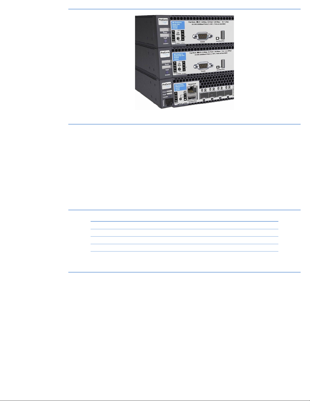
Figure 6: Closeup view of the HP ProCurve 6600 Switch Series LEDs
Processor
The CPU processor is a Freescale PowerPC 8540 operating at 667 MHz.
Memory
SDRAM
Synchronous Dynamic RAM (SDRAM) is used for the storage of uncompressed executable code and data
structures. The SDRAM consists of a 256 MB DDR-1 DIMM in the base module, expandable up to 1 GB. The
DDR-1 interface is 64 bits running at 166-MHz bus speed (333-MHz data rate).
Buffer memory
Table 1 highlights the amount of QDR SDRAM allocated for buffer memory for all 1-Gb and all 10-Gb data
ports for each of the 6600 series products.
Product Buffer memory for 1-Gb ports Buffer memory for 10-Gb ports
6600-24G switch (J9263A) 18 MB –
6600-24G-4XG switch (J9264A) 18 MB 18 MB
6600-48G switch (J9451A) 36 MB –
6600-48G-4XG switch (J9452A) 36 MB 36 MB
6600-24XG switch (J9265A) – 108 MB
14
Table 1: 6600 series buffer memory configurations
Flash memory
Both 24-port Gigabit products include 256 MB of Compact Flash and 4 MB of MirrorBit Flash. All other 6600
series products include 1 GB of Compact Flash memory as well as 4 MB of MirrorBit Flash. The MirrorBit Flash
is used for initial boot code. The Compact Flash is used for nonvolatile configuration storage (“NVRAM”).
Compressed image storage and the relatively large storage capacity allow multiple configurations and images
to be stored locally to facilitate upgrades and rollbacks during maintenance periods. The Compact Flash card
is removable for future upgrade capability if needed.
Because all application code is executed out of SDRAM, the Compact Flash may be programmed while the
switch is operational; that is, you can download new code onto the Compact Flash during system operation.
The Compact Flash is sized so that a backup copy of an older revision of application code also may be stored.
The system also allows you to hold up to three copies of configuration files, associating them to a particular
Flash image (primary => Config1, secondary => Config2, Active Running session => Config3).
Page 15
Console port
The console port allows for RS-232 serial connectivity for local management and configuration. For the 660048G, 6600-48G-4XG, and 6600-24XG switches, the console port is an RJ-45 connector. To connect to the
console, an RJ-45–to–DB-9 cable is provided with each switch to connect to the serial port on a laptop. The
6600-24G/6600-24G-4XG products offer a DB-9 serial console port for management access, and a DB-9–to–
DB-9 cable is provided. The part numbers for the various console port cables are as follows:
DB-9–to–DB-9 console cable: 5184-1894 (included with 6600-24G/24G-4XG switch)
RJ-45–to–DB-9 console adapter: 5189-6795 (included with 6600-48G/48G-4XG/24XG switch)
For a detailed description of the console cable pin-outs, please refer to the “Installation and Getting Started
Guide” located at www.hp.com/rnd/support/manuals/6600dc.htm
Ethernet out-of-band management (OOBM) port
The 6600-48G, 6600-48G-4XG, and 6600-24XG models offer an RJ-45 10/100 Ethernet management port
with isolated CPU and memory resources and a separate TCP/IP stack to provide control of the 6600 switch,
even in cases where the in-band network has succumbed to a broadcast storm or has become inaccessible
through misconfiguration. The out-of-band management (OOBM) port effectively provides in-band management
capabilities in an out-of-band context by enabling key services such as SSH, Telnet, TFTP, HTTP, SNTP, RADIUS,
TACACS, DNS, syslog, ping, and traceroute. “Appendix A: out-of-band management port” provides more
details about the capabilities of the OOBM port.
Auxiliary (USB) port
The connectivity side of the 6600 series includes a USB auxiliary port that is used to transfer configuration and
image files without the need to establish console or network access. The system image and configurations can
be copied to a USB memory stick, and the 6600 switch can copy the configuration and image from USB, just
as users typically would over the network. The auxiliary port is enabled by default, but can be deactivated as
part of the CLI and MIB structure.
The USB port is compatible with the 1.1 USB standard and only supports file storage.
6600 series system architecture
The following section provides an architectural review of each of the HP ProCurve 6600 switches.
HP ProCurve 6600-24G Switch (J9263A)
Management function
(on motherboard)
Mgmt. to N-chip comm.
NG
ASIC
NG
ASIC
24 gig MACs
24-Gb MACs
6 port
6 port
6 port
6 port
6 port
6-port
PHY
PHY
PHY
PHY
6 port
6 port
6-port
PHY
PHY
PHY
PHY
6 port
6 port
6 port
6-port
PHY
PHY
PHY
PHY
4-port
4 port
4 port
mGBIC
mGBIC
mGBIC
6 port
6 port
6-port
PHY
PHY
PHY
PHY
24-Gb ports
14.4-Gbps HSL
14.4-Gbps HSL
• Based on 3500yl-24G design
• 4 ports are dual personality (Gig-T or Gigabit fiber)
• No NGX ASIC (no 10-Gb uplink option)
• Runs same code as 3500yl/5400zl/8200zl switch
Based on 3500yl design
48.0-Gbps*
switching capacity
F1
F1
6
Hi-Speed
6
High-speed
links
Links
* 48.0 Gbps = 24x2(Fdx), although
F1 has a full capability of
172.8-Gbps switching
Figure 7: HP ProCurve 6600-24G Switch—ProVision ASIC architecture overview
15
Page 16

Description
The HP ProCurve 6600-24G Switch is a data center optimized, advanced Layer 3 1U stackable switch with
20 10/100/1000Base-T ports and 4 dual-personality ports. The 6600 series 1U form factor switches are
enhanced for server edge connectivity with front-to-back cooling, redundant hot-swappable power, and
redundant hot-swappable fans. The foundation for all these switches is a purpose-built, programmable ProVision
ASIC that allows the most demanding networking features, such as QoS and security, to be implemented in
a scalable yet granular fashion. With a variety of connectivity interfaces and expanded buffering, the 6600
switches offer excellent investment protection, flexibility, and scalability, as well as ease of deployment and
reduced operational expense.
Ports
•24 10/100/1000Base-T RJ-45 connectors
•4 dual-personality 1-GbE SFP (can be used in lieu of last four 10/100/1000Base-T ports)
Management connectivity
•DB-9 serial console port
HP ProCurve 6600-24G-4XG Switch (J9264A)
Management function
Based on 3500yl design
(on motherboard)
Mgmt. to N-chip comm.
14.4-Gbps HSL
14.4-Gbps HSL
• Based on 3500yl-24G design
NG
ASIC
NG
ASIC
24 gig MACs
24-Gb MACs
• 4 ports are dual personality (Gig-T or Gigabit fiber)
• NGX ASIC with 18 MB packet buffer
(3500yl series has 4.5 MB and 10-Gb ports)
• Runs same code as 3500yl/5400zl/8200zl switch
6 port
6 port
6 port
6 port
6 port
6-port
PHY
PHY
PHY
PHY
6 port
6 port
6-port
PHY
PHY
PHY
PHY
6 port
6 port
6 port
6-port
PHY
PHY
PHY
PHY
4-port
4 port
4 port
mGBIC
mGBIC
mGBIC
6 port
6 port
6-port
PHY
PHY
PHY
PHY
24-Gb ports
1
Figure 8: HP ProCurve 6600-24G-4XG Switch—ProVision ASIC architecture overview
105.6-Gbps*
switching capacity
F1
F1
6
Hi-Speed
6
High-speed
links
Links
14.4-Gbps HSL
14.4-Gbps HSL
* 105.6 Gbps = (24+28.8)x2(Fdx),
although F1 has a full capability of
172.8-Gbps switching
NGX
NGX
18MB pkt buffer
18-MB pkt buffer
4 10-Gb MACs
4 10gig MACs
Four 10 GbE ports
Four 10-GbE ports
SFP+
SFP+
SFP+
SFP+
SFP+
SFP+
port
port
port
port
port
port
SFP+
SFP+
SFP+
port
port
port
ASIC
ASIC
SFP+
SFP+
SFP+
port
port
port
16
Description
The HP ProCurve 6600-24G-4XG Switch is a data center optimized, advanced Layer 3 1U stackable switch
with 20 10/100/1000Base-T ports, 4 dual-personality ports, and 4 SFP+ 10-GbE integrated ports. The 6600
series 1U form factor switches are enhanced for server edge connectivity with front-to-back cooling, redundant
hot-swappable power, and redundant hot-swappable fans. The foundation for all these switches is a purposebuilt, programmable ProVision ASIC that allows the most demanding networking features, such as QoS and
security, to be implemented in a scalable yet granular fashion. With a variety of connectivity interfaces and
expanded buffering, the 6600 switches offer excellent investment protection, flexibility, and scalability, as well
as ease of deployment and reduced operational expense.
Page 17

The ASIC layout shown in Figure 8 for the data center focused 6600-24G-4XG switch adds an NGX ASIC to
provide a 10-Gb uplink capability to this switch model. Unlike the 3500yl-24G switch, where the yl 10-Gb
module is rear mounted, the 6600-24G-4XG switch moves the 10-Gb ports to the front of the switch for
simplified cabling.
Examining the Gigabit ports, the last four ports are dual personality, meaning they can be used as RJ-45
copper ports or mGBIC (or SFP) fiber ports. The 6600-24G-4XG switch offers four ports of 10-Gb using SFP+
port slots—instead of X2 slots used on earlier 10-Gb HP networking products. There is no CX4 option for these
SFP+ products, but HP networking offers a low-cost copper direct attach cable (or DAC) option that is based
on the Small Form Factor Committee (SFF-8431) standard. The DACs are essentially a preterminated cable
with SFP+ compatible transceivers. DAC products are available in 1-, 3-, and 7-m lengths, primarily for close
proximity connections to 10-Gb servers or other SFP+ switches, such as in the same server cabinet. The 6600
accessories portion of this guide provides further details about the direct attach options.
The fabric-switching capacity is listed the same as the 3500yl-24G switch, where we account for the added
NGX ASIC and its maximum capacity of 28.8 Gbps of throughput. Table 2 compares the 6600-24G/24G-4XG
architectures to that of the 3500yl-24G and 2910al-24G switches.
2910al-24G 6600-24G 6600-24G-4XG 3500yl-24G
Rack height 1U 1U 1U 1U
1-Gb RJ-45 24 24 24 24
1-Gb SFP 4* 4* 4* 4*
10-Gb SFP+ 4 (2 X2/2 CX4) – 4 4 (2 X2/2 CX4)
Max. 1-Gb wire-speed ports 24 24 24 24
Max. 10-Gb wire-speed ports 4 – 2 2
Management console port RJ-45 Serial DB-9 Serial DB-9 Serial DB-9
10-Gb port buffering 6 MB** – 18 MB 4.5 MB
Out-of-band mgmt. port – – – –
Power save option – – – –
Power supply 1 internal PS
(external PS option)
Routing/Switching capacity 128.0 Gbps 48.0 Gbps 101.8 Gbps 101.8 Gbps
Fabric capacity 128.0 Gbps 48.0 Gbps 105.6 Gbps 105.6 Gbps
Switch throughput 95.2 mpps 35.7 mpps 75.7 mpps 75.7 mpps
MAC address entries 16K 64K 64K 64K
ACL entries 0.5K 3K 3K 3K
Routing table entries 2K 10K 10K 10K
* Dual-personality ports
** 16-MB shared across all 1-Gb and 10-Gb ports
2 internal PS slots
(ships with 1 PS)
2 internal PS slots
(ships with 1 PS)
1 internal PS
(external PS option)
Table 2: 6600-24G/24G-4XG switches vs. 2910al-24G and 3500yl-24G switches
Ports
•24 10/100/1000Base-T RJ-45 connectors
•4 dual-personality 1-GbE SFP (can be used in lieu of last 4 10/100/1000Base-T ports)
•4 10-GbE SFP+ ports (10-GbE-only speeds)
•SFP and SFP+ slots are not interchangeable and only support HP networking-branded optics
Management connectivity
•DB-9 serial console port
17
Page 18

HP ProCurve 6600-48G Switch (J9451A)
Management function
Based on 5400zl design
(on motherboard)
Mgmt. to N-chip comm.
10/100 Out-of-Band Ethernet Management port
10/100 Ethernet out-of-band management port
ASIC
NG
NG
ASIC
24-Gb MACs
24 gig MACs
6-port
6-port
6-port
6 port
6 port
6 port
PHY
PHY
PHY
PHY
6 port
6 port
6 port
PHY
PHY
PHY
PHY
6-port
6 port
6 port
6 port
PHY
PHY
PHY
PHY
6 port
6 port
6 port
PHY
PHY
PHY
PHY
14.4-Gbps HSL
14.4-Gbps HSL
14.4-Gbps HSL
ASIC
NG
NG
ASIC
24-Gb MACs
24 gig MACs
6-port
6-port
6-port
6 port
6 port
6 port
6 port
6 port
6 port
6 port
6 port
6 port
PHY
PHY
PHY
PHY
PHY
PHY
PHY
PHY
PHY
PHY
PHY
PHY
14.4-Gbps HSL
6-port
6 port
6 port
6 port
PHY
PHY
PHY
PHY
24-Gb ports 24-Gb ports
Figure 9: HP ProCurve 6600-48G switch—ProVision ASIC architecture overview
switching capacity
12
4 port
4 port
4-port
mGBIC
mGBIC
mGBIC
96.0-Gbps*
F2
High-speed
links
• 4-Gb fiber ports (4 dual-personality ports)
• Runs same code as 3500yl/5400zl/8200zl switch
• No NGX ASIC (no 10-Gb uplink option)
* 96.0 Gbps = (24+24)x2(Fdx),
although F2 has a full capability of
345.6-Gbps switching
Description
The HP ProCurve 6600-48G Switch is a data center optimized, advanced Layer 3 1U stackable switch with
44 10/100/1000Base-T ports and 4 dual-personality ports. The 6600 series 1U form factor switches are
enhanced for server edge connectivity with front-to-back cooling, redundant hot-swappable power, and
redundant hot-swappable fans. The foundation for all these switches is a purpose-built, programmable ProVision
ASIC that allows the most demanding networking features, such as QoS and security, to be implemented in
a scalable yet granular fashion. With a variety of connectivity interfaces and expanded buffering, the 6600
switches offer excellent investment protection, flexibility, and scalability, as well as ease of deployment and
reduced operational expense.
The 6600-48G model is configured for 48-Gb copper connections, with the last four ports serving as dualpersonality options to accommodate mGBIC (SFP) fiber connections for longer-reach uplinks. Like the 660024G switch, the 6600-48G switch does not offer a 10-Gb uplink capability, as the primary use model is for
low-cost, top-of-rack aggregation of server iLO ports and other Ethernet-based management ports. Unlike the
6600-24G switch, the 6600-48G switch is based on the 5400zl design, using an F2 fabric ASIC and a newly
designed motherboard. Due to this redesign effort, HP networking offers the 6600-48G/48G-4XG and the
6600-24G/24G-4XG switches with a 10/100Base-T Ethernet out-of-band management (OOBM) port. The
OOBM port interfaces directly to the management function on the motherboard to provide a truly separate IP
stack that is independent of the Ethernet switch-forwarding plane. The OOBM port is in addition to the RJ-45
serial console port that was first introduced on the HP ProCurve 8212zl chassis. The OOBM port is discussed
further in the appendix of this document.
Ports
•48 10/100/1000Base-T RJ-45 connectors
•4 dual-personality 1-GbE SFP (can be used in lieu of last four 10/100/1000Base-T ports)
18
Management connectivity
•RJ-45 serial console port
•RJ-45 Ethernet out-of-band management port
Page 19

HP ProCurve 6600-48G-4XG Switch (J9452A)
Management function
Based on 5400zl design
(on motherboard)
Mgmt. to N-chip comm.
10/100 Out-of-Band Ethernet Management port
10/100 Ethernet out-of-band management port
NG
ASIC
ASIC
NG
24-Gb MACs
24 gig MACs
6 port
6 port
6 port
6 port
6 port
6-port
PHY
PHY
PHY
PHY
6 port
6 port
6-port
PHY
PHY
PHY
PHY
6 port
6 port
6 port
6-port
PHY
PHY
PHY
PHY
6 port
6 port
6-port
PHY
PHY
PHY
PHY
14.4-Gbps HSL
14.4-Gbps HSL
14.4-Gbps HSL
NG
ASIC
ASIC
NG
24-Gb MACs
24 gig MACs
6 port
6 port
6 port
6 port
6 port
6 port
6 port
6 port
6 port
6-port
6-port
6-port
PHY
PHY
PHY
PHY
PHY
PHY
PHY
PHY
PHY
PHY
PHY
PHY
14.4-Gbps HSL
6 port
6 port
6 port
6-port
PHY
PHY
PHY
PHY
24-Gb ports 24-Gb ports
1
Figure 10: HP ProCurve 6600-48G-4XG Switch—ProVision ASIC architecture overview
176.0-Gbps*
switching capacity
F2
12
High-speed
links
14.4-Gbps HSL
14.4-Gbps HSL
14.4-Gbps HSL
14.4-Gbps HSL
• No Gigabit fiber ports;
SFP+ ports are 10-Gb only
• Runs same code as
3500yl/5400zl/8200zl
switch
• Two NGX ASIC with 18-MB
pkt. buffer (3500yl switch has
4.5 MB) for full 40-Gb
wire-speed capability
* 176.0 Gbps = (24+24 + 20+20)x2(Fdx),
although F2 has a full capability of
345.6-Gbps switching
ASIC
ASIC
NGX
NGX
NGX
18-MB pkt. buffer
18MB pkt buffer
18MB pkt buffer
4 10gig MACs
4 10gig MACs
4 10-Gb MACs
ASIC
NGX
NGX
NGX
18-MB pkt. buffer
18MB pkt buffer
18MB pkt buffer
4 10-Gb MACs
4 wire-speed 10-GbE ports
SFP+
SFP+
SFP+
port
port
port
ASIC
ASIC
ASIC
4 10gig MACs
4 10gig MACs
Four Wirespeed
10 GbE
SFP+
SFP+
SFP+
SFP+
SFP+
SFP+
port
port
port
port
port
port
SFP+
SFP+
SFP+
port
port
port
Description
The HP ProCurve 6600-48G-4XG Switch is a data center optimized, advanced Layer 3 1U stackable switch
with 48 10/100/1000Base-T ports and 4 SFP+ 10-GbE integrated ports. The 6600 series 1U form factor
switches are enhanced for server edge connectivity with front-to-back cooling, redundant hot-swappable power,
and redundant hot-swappable fans. The foundation for all these switches is a purpose-built, programmable
ProVision ASIC that allows the most demanding networking features, such as QoS and security, to be
implemented in a scalable yet granular fashion. With a variety of connectivity interfaces and expanded
buffering, the 6600 switches offer excellent investment protection, flexibility, and scalability, as well as ease of
deployment and reduced operational expense.
To achieve wire-speed forwarding on all ports, the 6600-48G-4XG model is configured with two NGX
10-Gb ASICs. Each NGX connects to two downstream 10-Gb SFP+ ports, and therefore provides full line-rate
capacity across all four 10-Gb ports. Because each NGX is only connected to two 10-Gb ports, the maximum
throughput of each NGX ASIC is only counted as 20-Gb full-duplex (or 40-Gb switching). Thus, unlike the
3500yl-48G architecture, where the 4 x 10-Gb module connects to a single NGX ASIC, thereby achieving a
maximum throughput of 28.8 Gb across all four 10-Gb ports, the 6600-48G-4XG switch can achieve 40 Gb of
throughput.
19
Page 20

Table 3 details the comparison of the 6600-48G/48G-4XG switches, the 2910al-48G, and the 3500yl-48G
switches in more detail.
2910al-48G 6600-48G 6600-48G-4XG 3500yl-48G
Rack height 1U 1U 1U 1U
1-Gb RJ-45 48 48 48 48
1-Gb SFP 4* 4* – 4*
10-Gb SFP+ 4 (2 X2/2 CX4) – 4 4 (2 X2/2 CX4)
Max. 1-Gb wire-speed ports 48 48 48 48
Max. 10-Gb wire-speed ports 4 – 4 2
10-Gb port buffering 6 MB** – 36 MB 4.5 MB
Management console port RJ-45 RJ-45 RJ-45 Serial DB-9
Out-of-band mgmt. port – RJ-45 10/100 Ethernet RJ-45 10/100 Ethernet –
Power save option – Yes Yes –
Power supply 1 internal PS
(external PS option)
Routing/Switching capacity 176.0 Gbps 96.0 Gbps 176.0 Gbps 149.8 Gbps
Fabric capacity 176.0 Gbps 96.0 Gbps 176.0 Gbps 153.6 Gbps
Switch throughput 130.9 mpps 71.4 mpps 130.9 mpps 111.5 mpps
MAC address entries 16K 64K 64K 64K
ACL entries 0.5K 3K 3K 3K
Routing table entries 2K 10K 10K 10K
* Dual-personality ports
** 6 MB shared across all 1-Gb and 10-Gb ports
Note: The 6600-48G-4XG switch does not support 1-Gb mGBIC/SFP capability. The last four ports are exclusively for 10-Gb SFP+ transceivers; they are
not capable of running at Gigabit speeds.
2 internal PS slots
(ships with 1 PS)
2 internal PS slots
(ships with 1 PS)
1 internal PS
(external PS option)
Table 3: 6600-48G/48G-4XG switches vs. 2910al-48G and 3500yl-48G switches
With line-rate processing across all four 10-Gb SFP+ ports, the 6600-48G-4XG switch is an effective solution to
provide true non-blocking connectivity to 40-Gb servers with 40-Gb uplink capability (along with the increased
packet-buffer capabilities of the 6600 series for its 10-Gb ports—18 MB of packet buffering, in this case, per
pair of 10-Gb ports for 36-MB total in available 10-Gb memory. A similarly configured 3500yl-48G switch
with its 4 x 10-Gb yl module option would be oversubscribed if connected to 40-Gb servers with only 28.8-Gb
maximum throughput. The 3500yl-48G switch is also limited to 4.5 MB of packet buffer memory across all
10-Gb ports).
Ports
•48 10/100/1000Base-T RJ-45 connectors
•4 10-GbE SFP+ ports (10-GbE-only speeds)
Management connectivity
•RJ-45 serial console port
•RJ-45 Ethernet out-of-band management port
20
Page 21

For high-availability configurations with the 6600-48G-4XG switch, users should consider trunking the 10-Gb
uplinks across odd and even ports to take advantage of the dual paths to separate NGX chips, as shown in
Figure 11.
49
NGX
50 51 52
Trunk 1
Trunk 2
Figure 11: Recommended trunking uplink configuration for the 6600-48G-4XG switch
HP ProCurve 6600-24XG Switch (J9265A)
Based on 5400zl design
Management function
(on motherboard)
345.6.0-Gbps*
switching capacity
10/100 Out-of-Band Ethernet Management port
10/100 Ethernet out-of-band management port
28.8 Gbps 28.8 Gbps
12
28.8 Gbps
F2
High-speed
links
28.8 Gbps
* 345.6 Gbps = (12x14.4)x2(Fdx)
14.4-Gbps HSL
14.4-Gbps HSL
28.8 Gbps
28.8 Gbps
SFP+
SFP+
SFP+
ASIC
ASIC
18-MB pkt. buffer
Four 10 GbE ports
SFP+
SFP+
SFP+
SFP+
SFP+
SFP+
SFP+
SFP+
port
port
port
SFP+
port
port
port
port
port
port
NGX
NGX
18-MB pkt. buffer
18MB pkt buffer
4 10-Gb MACs
4 10gig MACs
Four 10 GbE ports
4 10-GbE ports 4 10-GbE ports 4 10-GbE ports 4 10-GbE ports 4 10-GbE ports 4 10-GbE ports
SFP+
SFP+
SFP+
port
port
port
1
ASIC
NGX
NGX
ASIC
18MB pkt buffer
4 10-Gb MACs
4 10gig MACs
SFP+
SFP+
SFP+
SFP+
SFP+
SFP+
port
port
port
port
port
port
port
port
port
NGX
NGX
18-MB pkt. buffer
18MB pkt buffer
4 10-Gb MACs
4 10gig MACs
Four 10 GbE ports
SFP+
SFP+
SFP+
SFP+
SFP+
SFP+
port
port
port
port
port
port
SFP+
SFP+
SFP+
port
port
ASIC
NGX
NGX
ASIC
18-MB pkt. buffer
18MB pkt buffer
4 10-Gb MACs
4 10gig MACs
Four 10 GbE ports
SFP+
SFP+
SFP+
SFP+
SFP+
SFP+
SFP+
SFP+
port
SFP+
port
port
port
port
port
port
port
port
port
SFP+
SFP+
SFP+
port
port
port
SFP+
SFP+
SFP+
port
port
port
ASIC
ASIC
NGX
NGX
18-MB pkt. buffer
18MB pkt buffer
4 10-Gb MACs
4 10gig MACs
Four 10 GbE ports
SFP+
SFP+
SFP+
SFP+
SFP+
SFP+
port
port
port
port
port
port
SFP+
SFP+
SFP+
ASIC
ASIC
NGX
18-MB pkt. buffer
18MB pkt buffer
4 10-Gb MACs
ASIC
NGX
ASIC
4 10gig MACs
Four 10 GbE ports
SFP+
SFP+
SFP+
SFP+
SFP+
SFP+
SFP+
SFP+
SFP+
SFP+
SFP+
port
port
port
SFP+
port
port
port
port
port
port
port
port
port
SFP+
SFP+
port
port
port
SFP+
SFP+
port
port
port
SFP+
SFP+
port
port
port
Figure 12: HP ProCurve 6600-24XG Switch—ProVision ASIC architecture overview
Description
The HP ProCurve 6600-24XG Switch is a data center optimized, advanced Layer 3 1U stackable 24 switch with
SFP+ 10-GbE ports. The 6600 series 1U form factor switches are enhanced for server edge connectivity with
front-to-back cooling, redundant hot-swappable power, and redundant hot-swappable fans. The foundation for
all these switches is a purpose-built, programmable ProVision ASIC that allows the most demanding networking
21
Page 22

features, such as QoS and security, to be implemented in a scalable yet granular fashion. With a variety
of connectivity interfaces and expanded buffering, the 6600 switches offer excellent investment protection,
flexibility, and scalability, as well as ease of deployment and reduced operational expense.
From a design standpoint, the 6600-24XG model is essentially the equivalent of a 5406zl chassis configured
with six 4 x 10-Gb modules. Each NGX network chip represents a node in the system with high-speed links
(HSLs) connecting to the interconnect fabric—F2 chip. Each HSL provides approximately 14.4 Gbps of data
bandwidth and up to 28.8 Gbps total per NGX interface ASIC. In addition, a management plane dedicates a
CPU to provide communications control between the NGX and F2 fabric chip. Throughput capacities are the
NGX full capacity of 28.8-Gbps full-duplex or 57.6-Gbps switching capacity per NGX ASIC. The datasheet
throughput values reflect this full fabric capacity of 345.6 Gbps of switching capacity. The ProVision ASIC
architecture section that follows covers a few specifics about the NGX ASIC, specifically port mappings to the
HSLs and throughput limitations and caveats.
Enhanced packet buffers
Each 10-Gb set of four ports is sharing an 18-MB packet buffer (compared to the 3500yl and zl modules’
4.5 MB of packet buffers).
Ports
•24 10-GbE SFP+ ports (10-GbE-only speeds)
Management connectivity
•RJ-45 serial console port
•RJ-45 Ethernet out-of-band management port
ProVision ASIC architecture
The ProVision ASIC architecture is the latest-generation HP networking ASIC technology and is used in the
ProCurve 6600 Switch Series, along with the 8200zl, 5400zl, 6200yl, and 3500yl product families. The
ProVision ASIC architecture consists of multiple network chips interconnected by an active crossbar fabric
chip. Depending on the flavor of the ProVision network chip used, the 6600 series product supports either
NG (Gigabit) or NGX (10-Gb) interfaces. Additionally, the 6600-24G/24G-4XG products utilize the F1 fabric
ASIC supporting up to high-speed links (HSLs) of 14.4 Gbps each for a maximum theoretical fabric capacity
of 172.8 Gbps full duplex, while the 6600-48G/48G-4XG and 6600-24XG switches utilize the F2 fabric ASIC
that provides up to 12 HSLs for a maximum theoretical fabric capacity of 345.6 Gbps full duplex.
Inside the ProVision ASIC architecture
Each NG/NGX network chip contains a full, hardware-based Layer 3 routing switch engine as well as Layer
4 filtering and metering capabilities. These latest ProVision ASICs are HP networking’s fourth generation of
internally developed switching platforms. The ProVision network switching engines execute all the packet
processing, including Layer 2 and Layer 3 lookups, Layer 2/Layer 3/Layer 4 filtering and forwarding decisions,
VLAN forwarding and routing, LACP trunking
capabilities and software implementation are common across ProCurve 6600, 8200zl, 5400zl, 6200yl, and
3500yl series switch families.
Classification and lookup
When an Ethernet packet first arrives, the classifier section determines the packet characteristics, its source
and destination addresses, VLAN affiliation, any priority specification, and so on. The packet is stored in input
memory; lookups into the table memory are done to determine routing information; and a ProVision ASICspecific packet header is created for the packet with this information. This header is then forwarded to the
Policy Enforcement Engine.
2
, and priority queuing determinations. The ProVision hardware
22
2
HP networking’s term “trunking” is the aggregation of multiple physical links into one logical link. Other vendors may refer to this as Channels or Link
Aggregated Groups (LAGs).
Page 23

Policy Enforcement Engine
The ProVision network ASICs contain the Policy Enforcement Engine. This engine provides fast packet
classification to be applied to ACLs, QoS, rate limiting, and some other features through an onboard Ternary
Content Addressable Memory (TCAM). Some of the variables that can be used include source and destination
IP addresses (which can follow specific users), TCP/UDP port numbers and ranges (apply ACLs to an
application that uses fixed-port numbers or ranges). More than 14 different variables can be used to specify the
packets to which ACL and QoS rules, rate-limiting counters, and others are to be applied.
The Policy Enforcement Engine provides a common front end for the user interface to ACLs, QoS, rate limiting,
and some other services. In subsequent software releases for the switches, more features can take advantage of
the Policy Enforcement Engine to provide a powerful, flexible method for controlling the network environment.
For example, traffic from a specific application can be raised in priority for some users, blocked for other users,
and limited in bandwidth for still other users. After the Policy Enforcement Engine, the header is then forwarded
to the programmable section of the network switch engine.
Network switch engine programmability
Each ProVision ASIC switch engine contains multiple programmable units, making them true network processor
units (NPUs). One of the functions of the NPU is to analyze the header of each packet as it comes into the
switch. The packet’s addresses can be read with the switch making forwarding decisions based on this
analysis. For example, if a packet’s IEEE 802.1Q tag needs to be changed to re-map the packet priority, the
ProVision ASIC needs to look at each packet to see if any particular one needs to be changed. This packet-bypacket processing has to occur very quickly to maintain overall wire-speed performance—a capability of the
ProVision ASICs.
To broaden the flexibility of the ProVision ASICs, a programmable function is included for its packet processing.
This NPU function allows HP networking designers the opportunity to make future changes or additions in the
packet-processing features of the ASIC by downloading new software to it. Thus, new features needing highperformance ASIC processing can be accommodated, extending the useful life of the switch without the need to
upgrade or replace the hardware.
HP networking’s first venture into switching ASIC designs began in 1995, with the introduction of the 2000
switch. The concept of adding the programmable functionality of the NPU within a switching ASIC was
designed and implemented in the popular ProCurve Switch 4000M product family introduced in 1998.
ProCurve’s 5300xl programmable capability was a third-generation design based on the original ProCurve
Switch 4000M implementation. The programmable capability was used to give both the ProCurve Switch
4000M and Switch 5300xl new ASIC-related features well after initial release of those products. Customers
with existing units could benefit from the new features through free software downloads. The customer’s
investment in the ProCurve Switch 4000M and 5300xl is preserved by providing new functionality not
otherwise possible without the ASIC NPU programmability. Being based on the ProCurve Switch 4000M and
5300xl implementations, the NPU capabilities of the ProVision ASICs used in the ProCurve 6600, 8200zl,
5400zl, 6200yl, and 3500yl series are a fourth-generation design, following the designs of the 5300xl and
4000M switch, and the original 2000 switch.
Fabric interfaces
After the packet header leaves the programmable section, the header is forwarded to the fabric interface. The
fabric interface makes final adjustments to the header based on priority information, multicast grouping, and
other factors, and then uses this header to modify the actual packet header as necessary.
The fabric interface then negotiates with the destination ProVision ASICs for outbound packet buffer space.
Finally, the ProVision ASIC’s fabric interface forwards the entire packet through the Fabric ASIC to an awaiting
output buffer on the ProVision ASICs that controls the outbound port for the packet. Packet transfer from the
ProVision network ASICs to the Fabric ASIC is accomplished using the 28.8-Gbps full-duplex connection, which
is also managed by the fabric interface.
ProVision ASIC CPU
Each ProVision ASIC contains its own CPU for learning Layer 2 nodes, packet sampling for the XRMON/
sFlow function, handling local MIB counters, and running other module-related operations. Overall, the local
CPU offloads the master CPU by providing a distributed approach to general housekeeping tasks associated
with every packet. MIB variables, which need to be updated with each packet, can be done locally. The
23
Page 24

Layer 2 forwarding table is kept fresh through the use of this CPU. Other per-port protocols, such as Spanning
Tree Protocol and LACP, also are run on this CPU. The local CPU, being a full-function microprocessor, allows
functionality updates through future software releases.
Fabric ASIC
The Fabric ASIC provides the crossbar fabric for interconnecting the modules together. The use of a crossbar
allows wirespeed connections simultaneously from any module to any other module. As mentioned in the
“ProVision ASIC architecture” section, the connection between the Fabric ASIC and each interface module’s
ProVision ASIC (either NG or NGX) is through a 28.8-Gbps full-duplex link via two 14.4-Gbps HSLs.
Management subsystem
The management subsystem is responsible for overall switch management and consists of a CPU, flash memory
to hold program code, processor memory for code execution, a console interface, and other system support
circuitry to interface and control the ProVision ASICs. In the case of the 6600 switch series, the management
subsystem is fixed on the motherboard and does not allow for removability or upgradability.
ProVision hardware resiliency
Many functions required in a switch have been implemented in the single ASIC on the module. What takes a
number of chips in other vendor products is achieved in a single ProVision ASIC in the 6600 series. This keeps
the part count down, raising overall reliability of the module a significant degree.
Another engineering aspect in the ASIC is hardware error detection, with correction in software for the memory
used by the switch. This includes the memory used for forwarding the network traffic, such as the routing and
forwarding tables, the Policy Enforcement Engine information, multicast tables, and other data structures. Traffic
sent across the backplane uses a protocol to check that there is space available at the destination module so
that fabric data is not lost.
6600 series accessories
To facilitate deployment, high-availability configurations, and sparing, the 6600 series offers a variety of
accessories to meet a range of needs. Table 4 summarizes the various 6600 series accessories that are
available.
Product # Description
J9305A HP ProCurve 6600 Switch Premium License
J9269A HP ProCurve 6600 Switch Power Supply
J9271A HP ProCurve 6600 Switch Fan Tray
J9469A HP ProCurve 6600 Rack Mount Kit
J9480A HP ProCurve 6600 Air Plenum
J9481A HP ProCurve 6600-24G/24G-4XG Plenum
Table 4: 6600 series accessories
HP ProCurve 6600 Switch Premium License (J9305A)
With a flexible approach to upgradability and licensing, the 6600 switches can run the base feature group
initially, and then be upgraded later to run the Premium License feature group. The Premium License offers
advanced Layer 2 and 3 capabilities, including Q-in-Q, VRRP, PIM-SM, PIM-DM, and OSPFv2, and OSPFv3.
The Premium License can be transferred to another switch, as long as the license remains in the 6600 family.
24
HP ProCurve 6600 Switch Power Supply (J9269A)
See reference in earlier text to HP ProCurve 6600 Switch Power Supply (J9269A).
Page 25

HP ProCurve 6600 Switch Fan Tray (J9271A)
See reference in earlier text to HP ProCurve 6600 Switch Fan Tray (J9271A).
Rack mounting options
2-post telco racks
As part of the 6600 series package, each switch ships with rack ears for mounting in 2-post telco racks.
Additional rack mount options and accessories are available detailed subsequently below.
4-post racks: HP ProCurve 6600 Series Rack Mount Kit (J9469A)
For mounting in 4-post server or networking cabinets, the HP ProCurve 6600 Series Rack Mount Kit is required.
The rack kit provides two telescoping rails that span the depth of the cabinet and provide a mounting range
that extends from 26 inches to 36 inches. The rail kit supports square-hole caged nut racks utilizing the EIA
310-d hole size of 3/8 inch x 3/8 inch (.375 in. x .375 in.).
The rail kit also supports round hole racks at 7.2-mm to 7.3-mm diameter. A picture of the 6600 series rail kit is
shown in Figure 13, and the mounting instructions can be found at
www.hp.com/rnd/support/manuals/6600dc.htm.
6600 rail kit contents
Left rail x 1
Right rail x 1
Hardware kit
Screw x 4
Stud x 4
Zip tie x 2
Rack bracket x 2 (5003-1452)
Figure 13: HP ProCurve 6600 Rack Mount Kit (J9469A)
HP 10000 series server racks: HP 10000 Series Rack Mount Kit (5070-0145) for
6600 series
While the HP ProCurve 6600 Series Rack Mount Kit works with HP 10000 series racks, some customers
prefer to order preconfigured server and networking solutions that are rack shipped directly from HP. For these
types of orders, the 10000 series rack mount kit—orderable via the HP part store (www.partsurfer.hp.com)—
is required. The 10000 series rack mount kit provides two fixed rails that span the depth of the cabinet. A
picture of the 10000 series rail kit is shown in Figure 14, and the mounting instructions can be found at
www.hp.com/rnd/support/manuals/6600dc.htm.
10000 series rack kit contents
10000 series rails x 2
M6 screw x 12
M6 cage nut x 12
Captive washer for M6 x 12
x 4 to attach rail to rack
x 2 to attach bracket to rack
M4x0.7 8-mm FH screw x 4
Rack bracket x 2 (5003-1452)
Hold-down brackets x 2
Figure 14: HP 10000 Series Rack Mount Kit (5070-0145) for 6600 series
25
Page 26

6600 series air plenums
The HP ProCurve 6600 Series Air plenum is designed to help preserve cold-aisle/hot-aisle separation for
improved cooling efficiency when the 6600 switch is co-located with top-of-rack servers. In typical top-of-rack
server connectivity environments, the Ethernet ports face the hot aisle to align with server I/O. When a switch
is mounted in a server rack, it is typically positioned toward the back of the rack to facilitate cabling, which
usually leaves a sizeable air gap in the rack where cold air can flow around the switch. The 6600 series air
plenum provides an enclosed pathway where cold air cannot escape around the switch and thus facilitates hotaisle and cold-aisle separation. This plenum is especially useful in environments where customers are concerned
about maintaining temperature and pressure gradients due to limited cooling capacity, or want to save on
cooling costs.
Figure 15 details what the 6600 air plenum would look like mounted with a 6600 switch with the 4-post rail kit.
Hot-aisle (40°C)
6600 series air plenum
ProCurve 6600
Switch Series
connectivity side
Cold-aisle (25°C)
power supply side
Figure 15: HP ProCurve 6600 Series Air Plenum
HP ProCurve 6600 Series Air Plenum Kit (J9480A)
The 6600 series air plenum helps promote stronger hot-aisle/cold-aisle separation by maintaining temperature
and pressure gradients in configurations where the 6600 switch is co-located with servers at the top of rack.
The air plenum prevents cold air from leaking around sides of the 6600 switch to promote more efficient
cooling and is recommended with installations where the 6600 switch is mounted with Ethernet ports facing the
hot aisle. The 6600 series air plenum (J9480A) is designed for use with the 6600-48G, 6600-48G-4XG, and
6600-24XG switches. Figure 16 details the air plenum kit.
26
Note: For use with the 6600-48G, 6600-48G-4XG, and 6600-24XG switches
Figure 16: HP ProCurve 6600 Series Air Plenum Kit (J9480A)
HP ProCurve 6600-24G/24G-4XG Air Plenum (J9481A)
The 6600-24G/24G-4XG air plenum is used with 6600-24G and 6600-24G-4XG switches that require a
longer plenum due to shorter product depth. The plenum helps promote stronger hot-aisle/cold-aisle separation
by maintaining temperature and pressure gradients in configurations where the 6600 switch is co-located with
Page 27

servers at the top of rack. The air plenum prevents cold air from leaking around sides of the 6600 switch to
promote more efficient cooling and is recommended with installations where the 6600 switch is mounted with
Ethernet ports facing the hot aisle. Figure 17 details this particular air plenum.
Note: For use with the 6600-24G and 6600-24G-4XG switches
Figure 17: HP ProCurve 6600-24G/24G-4XG Air Plenum (J9481A)
Transceivers and direct attach cables
Depending on the needs of the environment, the 6600 series provides a range of optics choices to best match
the desired configuration. Many of the 6600 series switch models provide dual-personality ports to allow for
SFP 1-Gb connectivity over longer distances that exceed copper ranges. Additionally, most of the 6600 series
switches also support SFP+ for 10-Gb connectivity with both fiber-optic transceiver as well as low-cost options
over shorter runs using direct attach cables (DACs). As detailed below, the DACs come in 1-m, 3-m, and 7-m
lengths to facilitate uplinks to aggregation switches at the end of row or to also allow for server connectivity for
those devices that support 10-Gb NICs.
1-Gb SFP (mini-GBIC) transceivers
•J8177B or C—HP ProCurve Gigabit 1000Base-T Mini-GBIC
•J4858C—HP ProCurve Gigabit-SX-LC Mini-GBIC
•J4859C—HP ProCurve Gigabit-LX-LC Mini-GBIC
•J4860C—HP ProCurve Gigabit-LH-LC Mini-GBIC
10-Gb SFP+ transceivers
•J9150A—HP ProCurve 10-GbE SFP+ SR Transceiver
•J9151A—HP ProCurve 10-GbE SFP+ LR Transceiver
•J9152A—HP ProCurve 10-GbE SFP+ LRM Transceiver
10-Gb SFP+ direct attach cables
•J9281B—HP ProCurve 10-GbE SFP+ 1m Direct Attach Cable
•J9283B—HP ProCurve 10-GbE SFP+ 3m Direct Attach Cable
•J9285B—HP ProCurve 10-GbE SFP+ 7m Direct Attach Cable
Because SFP+ is a relatively new optical form factor for HP networking, Table 5 provides a comparison
between SFP and X2 for those more familiar with X2 transceiver options.
Feature SFP+ X2
Power consumption
SR 1 W/port 4 W/port
LRM 1.5 W/port 4 W/port
LR 1 W/port 4 W/port
Twinax direct attach cable 0.1 W/port (estimated) –
Connector type LC SC
Table 5: SFP+ vs. X2 optics
27
Page 28

Overview of features and benefits
The ProCurve 6600 Switch Series, like the 8200zl, 5400zl, 6200yl, and 3500yl series switches, uses the same
software image base (letter designated K-code, for example, K.14.xx). The 6600 switch series offers a premium
software license for advanced Layer 2 and Layer 3 services: Q-in-Q, PIM-SM, PIM-DM, OSPFv2, OSPFv3, and
VRRP. The primary differences among the ProVision switch families are hardware-related and include such
aspects as port density and PoE support, as well as support for redundant power supplies and fans.
The following summary of features and benefits applies to the ProCurve 6600 Switch Series.
Feature Benefits
Data center optimized
Seamless core-to-edge
capabilities
Front-to-back, reversible
airflow
Redundant, hot-swappable
fan tray
Redundant, hot-swappable
power supplies
64K MAC address
scalability
sFlow for enhanced network
visibility
Enhanced buffering Improves network utilization for “bursty” client/server transactions such as iSCSI and Web 2.0 applications.
Jumbo frames Provide scalability in throughput up to frame sizes of 9216 bytes for iSCSI attachment.
Automated server
provisioning
Performance
ProVision ASIC technology Powered by the ProVision ASICs, the switch families offer state-of-the-art, high-capacity, switch fabric
Selectable queue
configurations
Security enabled
Source port filtering Allows customers to control port access at the physical level—increasing security in a Layer 2 environment.
IP and MAC lockdown/
lockout
Virus throttle Connection rate-filtering thwarts viruses from spreading by blocking routing from certain hosts exhibiting
ICMP rate limiting Throttles denial-of-service (DoS) attacks or other malicious behavior that uses high-volume ICMP traffic.
Switch CPU protection Provides automatic protection against malicious network traffic trying to shut down the switch.
Detection of malicious
attacks
DHCP protection Blocks DHCP response packets from being forwarded if received from an unauthorized port.
BPDU port protection Blocks Bridge Protocol Data Unit (BPDU) on ports that should not be receiving BPDUs, preventing forged BPDU
Dynamic ARP protection Blocks ARP broadcast from unauthorized hosts, preventing eavesdropping or data theft of network data.
Dynamic IP lockdown Works with DHCP protection to block traffic from unauthorized host, preventing IP source address spoofing.
Filtering capabilities Include fast, flexible access control lists (up to 3,000) filtering on such parameters as source port, multicast MAC
ProCurve Identity Driven
Manager (IDM)
Port security Port security, MAC lockdown, and MAC lockout protection for restricting access to the network through a switch
Reduces complexity and provides choice and flexibility for top-of-rack and end-of-row server connectivity.
Enhances airflow to align with servers and storage to promote lower-cost top-of-rack networking architectures,
and reduces cooling needs.
N+N fans improve availability and serviceability that increase uptime.
N+1 power supply configuration improves uptime.
Industry-leading MAC address table size facilitates data center virtual server scalability.
Supports sFlow packet sampling to provide real-time visibility to monitor traffic across all data ports at up to
10-Gb wire speed.
Integrates seamlessly with ProCurve Data Center Connection Manager and HP Network Automation management
tool suite to simplify provisioning and reduce operating expense.
performance.
Increase performance by selecting the number of hardware-forwarding queues and associated memory buffer
that best meet the requirements of network applications.
Provides protection against known unauthorized hosts accessing the network.
abnormal traffic behavior.
Monitors 10 types of network traffic and sends warnings when anomalies potentially caused by malicious attacks
are detected.
attack.
address, and other protocols.
ProCurve IDM to dynamically apply security, access, and performance settings to infrastructure devices based on
approved user, location, and time.
port.
28
Page 29

Feature Benefits
Multiple user authentication
methods
Secure management access SSH, SSL, TACACS+, and Secure FTP encryption of switch management and configuration traffic—secures the
Client-based access control using IEEE 802.1X, Web-based, MAC-based authentication, RADIUS, and TACACS+.
At initial release, the combinations of authentication methods allowed simultaneously on a port are IEEE 802.1X/
Web and 802.1X/MAC.
network infrastructure from unauthorized access.
Redundancy and high availability
Redundancy protocols Protocols providing high availability include IEEE 802.1Q Multiple Spanning Tree Protocol, Switch Meshing, and
Virtual Router Redundancy Protocol (Premium License).
Operational intelligence
Policy Enforcement Engine Policy Enforcement Engine is user-configured to select packets that are then forwarded or dropped (based on
ACLs, QoS, and rate limiting). The engine is fast and can look for multiple variables, such as an IP address and
port number, in a single pass through a packet. Provides a common user experience regardless of which switch
the user is connected to.
Operational flexibility
L3 services at L2 Enforce ACLs, QoS, and other features using Layer 2/3/4 source, destination, and port addresses without
Premium License Flexible approach to licensing. The 6600 switches can run the base feature group initially and then be upgraded
needing an expensive software license.
later to run the Premium License feature group, if advanced Layer 3 features are needed. The Layer 3 features
include VRRP, PIM-SM, PIM-DM, OSPFv2, and OSPFv3. A Premium License can be transferred to another switch,
as long as the license remains in the same hardware family.
QoS enforcement
Bandwidth shaping/control Guaranteed minimums can be applied to traffic that must always get through the switch. Enforced maximums can
Multiple QoS parameters QoS based on TCP/UDP ports and other variables allows precise control of packet priority—providing timely
be used to limit problem clients’ bandwidth to no more than a set amount.
delivery of mission-critical data. Eight priority levels mapped to eight hardware queues can be used to set
outgoing IP priority.
Supports standard protocols
IP Routing Supports RIPv1, RIPv2, OSPFv2, OSPFv3, and static routes.
OSPF requires the Premium License for the 6600, 5400zl, and 3500yl switches.
Is standard on the 8200zl and 6200yl series switches.
VLANs Supports IEEE 802.1Q with 2,048 concurrent VLANs, Group VLAN Registration Protocol (GVRP).
IP Multicast Supports PIM-SM, PIM-DM, and IGMP data-driven snooping.
Low cost of ownership
Future-proofing Programmable ASICs allow some future requirements to be implemented without replacing the switch.
Intelligent Edge features can be upgraded to Premium License features on the 6600, 5400zl, and 3500yl
switches, allowing an edge switch to be redeployed as a distribution switch.
♦
ProCurve Lifetime Warranty
Next-business-day advance replacement for as long as you own the product (available in most countries).
Applies to all components and accessories of the 6600 series.
♦
For as long as you own the product, with next-business-day advance replacement (available in most countries). The following hardware products have a
five-year hardware warranty for the disk drive and lifetime hardware warranty (for as long as you own the product) for the rest of the module: HP ProCurve
ONE Services zl Module, HP ProCurve Threat Management Services zl Module, and HP ProCurve MSM765zl Mobility Controller. The following hardware
products and their related series modules have a one-year hardware warranty with extensions available: HP ProCurve Routing Switch 9300m series,
HP ProCurve Switch 8100fl series, HP ProCurve Net work Access Controller 800, and HP ProCurve DCM Controller. The following hardware products have
a one-year hardware warranty with extensions available: HP ProCurve M111 Client Bridge, HP ProCurve MSM3xx-R Access Points, HP ProCurve MSM7xx
Mobility and Access Controllers, HP ProCurve RF Manager IDS/IPS Systems, HP ProCurve MSM Power Supplies, HP ProCurve 1-Port Power Injector,
HP ProCurve CNMS Appliances, and HP ProCurve MSM317 Access Device. Standalone software, upgrades, or licenses may have a different warranty
duration. For details, refer to the ProCurve Software License, Warranty, and Support booklet at www.hp.com/go/procurve/warranty
29
Page 30

Feature set summary
Additional details about the ProCurve 6600 Switch Series and 8200zl, 5400zl, 6200yl, and 3500yl series
features include the following:
Data center optimized
•Front-to-back airflow: designed to be co-located at the top of a server rack, the 6600 series supports front-to-
back airflow (mechanically reversible) to support hot-aisle/cold-aisle configurations; the N+N fan tray is also
hot-swappable, allowing easy replacement in the rack
•Modular internal power supplies: supports redundant, hot-swappable power supply configurations (units ship
with one supply); power load is shared across dual supplies
•Server-to-switch distributed trunking: supports Layer 2 LACP groups from a single server across two different
switches for active-active server NIC teaming configurations
•Power-down idle ports: power-down blocks of idle Gigabit and 10-GbE ports to save power; idle ports can
be reinitialized without rebooting; available on 6600-24XG, 6600-48G, and 6600-48G-4XG models
•Out-of-band management: remotely monitor and manage switch via Ethernet out-of-band management port;
eliminate need for terminal server network; available on 6600-24XG, 6600-48G, and 6600-48G-4XG
models
•Deployment/serviceability: data connectivity and management ports are all front-side accessible, and power
supplies and fan trays are rear-side accessible to allow for easy maintenance and in-rack serviceability
Management
•Remote Intelligent Mirroring: mirrors ingress/egress ACL-selected traffic from a switch port or VLAN to a local
or remote 8200zl, 6600, 6200yl, 5400zl, and 3500yl switch port anywhere on the network
•RMON, XRMON, and sFlow v5: provide advanced monitoring and reporting capabilities for statistics, history,
alarms, and events
•Uni-Directional Link Detection (UDLD): monitors cable between two switches and shuts down the ports on both
ends if the cable is broken, turning the bi-directional link into uni-directional; this prevents network problems
such as loops
•IEEE 802.1AB Link Layer Discovery Protocol (LLDP): automated device discovery protocol for easy mapping by
network management applications
•Management simplicity: common networking features and CLI implementation (common throughout
HP ProCurve 8200zl, 6600, 6200yl, 5400zl, and 3500yl switches)
•Command authorization: leverages RADIUS to link a custom list of CLI commands to individual network
administrator’s login; also provides an audit trail
•Friendly port names: allow assignment of descriptive names to ports
•Multiple configuration files: can be stored to the flash image
•Dual flash images: provide independent primary and secondary operating system files for backup while
upgrading
30
Connectivity
•IPv6:
− IPv6 Host: switches are managed and deployed at the IPv6 network’s edge
− Dual stack (IPv4/IPv6): transitions from IPv4 to IPv6, supporting connectivity for both protocols
− MLD snooping: forwards IPv6 multicast traffic to the appropriate interface, preventing traffic flooding
− IPv6 ACL/QoS: supports ACL and QoS for IPv6 network traffic
•Auto-MDIX: automatically adjusts for straight-through or crossover cables on all 10/100 and 10/100/1000
ports
•Jumbo frames: on Gigabit and 10-Gb ports, allow high-performance remote backup and disaster-recovery
services with frame size of 9216 bytes
Page 31

Performance
•High-speed/-capacity architecture: based on the purpose-built ProVision ASICs to provide superior system
performance and scalability
•Selectable queue configurations: increase performance by selecting the number of queues and associated
memory buffering that best meet the requirements of network applications
Resiliency and high availability
•IEEE 802.3ad Link Aggregation Control Protocol (LACP) and ProCurve trunking: support up to 60 trunks, each
with up to 8 links (ports) per trunk
•IEEE 802.1s Multiple Spanning Tree: provides high link availability in multiple VLAN environments by allowing
multiple spanning trees; provides legacy support for 802.1D–1998 and IEEE 802.1w
•Virtual Router Redundancy Protocol (requires Premium License): VRRP allows groups of two routers to
dynamically back each other up to create highly available routed environments
•Server-to-switch distributed trunking: allows a server to connect to two switches with one logical trunk that
consists of multiple physical connections; enables load-balancing and increases resiliency
•Sparing simplicity: common power supplies, fan trays, and transceivers are used among the 6600 series
products
Layer 2 switching
•ProCurve switch meshing: dynamically load-balances across multiple active redundant links to increase
available aggregate bandwidth
•GARP VLAN Registration Protocol: allows automatic learning and dynamic assignment of VLANs
•IEEE 802.1ad Q-in-Q (requires Premium License): increases the scalability of Ethernet network by providing a
hierarchical structure; connects multiple LANs on high-speed campus or metro network
•IEEE 802.1v protocol VLANs: isolate select non-IPv4 protocols automatically into their own VLANs
Layer 3 services
•Loopback interface address: defines an address in RIP and OSPF that can always be reachable, improving
diagnostic capability
•UDP helper function: UDP broadcasts can be directed across router interfaces to specific IP unicast or subnet
broadcast addresses and prevent server spoofing for UDP services such as DHCP
Layer 3 routing
•RIP: provides RIPv1 and RIPv2 routing
•Static IP routing: provides manually configured routing; includes ECMP capability
•OSPF (requires Premium License): provides OSPFv2 for IPv4 and OSPFv3 for IPv6 routing
•Route maps: provide more control during route re-distribution; allow filtering and altering of route metrics
Security
•Source-port filtering: allows only specified ports to communicate with each other
•RADIUS/TACACS+: eases switch management security administration by using a password authentication
server
•Secure Shell (SSHv2): encrypts all transmitted data for secure, remote command-line interface (CLI) access
over IP networks
•Port security: allows access only to specified MAC addresses, which can be learned or specified by the
administrator
•MAC address lockout: prevents particular configured MAC addresses from connecting to the network
•Detection of malicious attacks: monitors 10 types of network traffic and sends a warning when an anomaly
that potentially can be caused by malicious attacks is detected
•Secure FTP: allows secure file transfer to/from the switch; protects against unwanted file downloads or
unauthorized copying of switch configuration file
•Switch management logon security: can require either RADIUS or TACACS+ authentication for secure switch
CLI logon
•Secure management access: all access methods—CLI, GUI, or MIB—are securely encrypted through SSHv2,
SSL, and/or SNMPv3
31
Page 32

•ICMP throttling: defeats ICMP denial-of-service attacks by enabling any switch port to automatically throttle
ICMP traffic
•Virus throttling: detects traffic patterns typical of WORM-type viruses and either throttles or entirely prevents
the ability of the virus to spread across the routed VLANs or bridged interfaces, without requiring external
appliances
•STP BPDU port protection: blocks Bridge Protocol Data Units (BPDUs) on ports that do not require BPDUs,
preventing forged BPDU attacks
•Dynamic IP lockdown: works with DHCP protection to block traffic from unauthorized hosts, preventing IP
source address spoofing
•DHCP protection: blocks DHCP packets from unauthorized DHCP servers, preventing denial-of-service attacks
•Dynamic ARP protection: blocks ARP broadcasts from unauthorized hosts, preventing eavesdropping or theft
of network data
•USB Secure Autorun: deploys, diagnoses, and updates switch using USB flash drive; works with secure
credential to prevent tampering
•STP Root Guard: protects root bridge from malicious attack or configuration mistakes
•Management Interface Wizard: CLI-based step-by-step configuration tool helps ensure that management
interfaces such as SNMP, telnet, SSH, SSL, Web, and USB are secured to desired level
•Access control lists (ACLs): provide filtering based on the IP field, source/destination IP address/subnet, and
source/destination TCP/UDP port number on a per-VLAN or per-port basis
•Multiple user authentication methods:
− Multiple IEEE 802.1X users per port: provides authentication of multiple IEEE 802.1X users per port; prevents
user “piggybacking” on another user’s IEEE 802.1X authentication
− Web-based authentication: authenticates from Web browser for clients that do not support IEEE 802.1X
supplicant; customized remediation can be processed on an external Web server
− MAC-based authentication: client is authenticated with the RADIUS server based on client’s MAC address
− Concurrent IEEE 802.1X, Web, and MAC authentication schemes per port: switch port will accept up to 32
sessions of IEEE 802.1X, Web, and MAC authentications
•Switch CPU protection: provides automatic protection against malicious network traffic trying to shut down the
switch
•Identity-driven ACL: enables implementation of a highly granular and flexible access security policy specific
to each authenticated network user
•Secure Sockets Layer (SSL): encrypts all HTTP traffic, allowing secure access to the browser-based
management GUI in the switch
•Security banner: displays a customized security policy when users log in to the switch
32
Multicast support
•IP multicast routing (requires Premium License): includes PIM Sparse and Dense modes to route IP multicast
traffic
•IP multicast snooping (data-driven IGMP): automatically prevents flooding of IP multicast traffic
Quality of Service (QoS)
•Layer 4 prioritization: enables prioritization based on TCP/UDP port numbers
•Class of Service (CoS): sets the IEEE 802.1p priority tag based on IP address, IP Type of Service (ToS), L3
protocol, TCP/UDP port number, source port, and DiffServ
•Bandwidth shaping:
− Port-based rate limiting: per-port ingress/egress enforced maximum bandwidth
− Classifier-based rate limiting: use ACL to enforce maximum bandwidth for ingress traffic on each port
− Guaranteed minimum: per-port, per-queue egress-based guaranteed minimum bandwidth
•Advanced classifier-based QoS: classifies traffic using multiple match criteria based on L2/L3/L4 information;
applies QoS policies such as setting priority level and rate limit to selected traffic per port or per VLAN
•Traffic prioritization: allows real-time traffic classification into eight priority levels mapped to eight queues
Page 33

Warranty and support
♦
•ProCurve Lifetime Warranty
: for as long as you own the product, with next-business-day advance
replacement (available in most countries)
•Electronic and telephone support: limited electronic and telephone support is available from HP; refer to the
HP website at www.procurve.com/support for details on the support provided and the period during which
support is available
•Software releases: refer to the HP website at www.procurve.com/support for details on the software releases
provided and the period during which software releases are available
Standards and protocols
Refer to the HP ProCurve Switch 6600 Series datasheet for the latest standards support available at
www.procurve.com/products/pdfs/datasheets/HP_ProCurve_6600_Switch_Series.pdf.
Capacity, performance, and features
6600 series comparison
Table 6 provides a comparison of several categories of capacity and performance levels for the ProCurve
6600 Switch Series. These include the routing and switching capacity (Gbps), switch fabric speed (Gbps),
maximum number of 1 Gbps ports that can operate concurrently at wire speed, the maximum number of
10-Gbps ports that can operate concurrently at wire speed, and the size of the routing table (entries).
6600-24G 6600-24G-4XG 6600-48G 6600-48G-4XG 6600-24XG
Rack height 1U 1U 1U 1U 1U
1-Gb RJ-45 24 24 48 48 –
1-Gb SFP 4* 4* 4* – –
10-Gb SFP+ – 4 – 4 24
Max. 1-Gb wire-speed ports 24 24 48 48 –
Max. 10-Gb wire-speed ports – 2 – 4 12
Out-of-band mgmt. port – – Yes Yes Yes
Power save option – – Yes Yes Yes
Routing/Switching capacity 48.0 Gbps 101.8 Gbps 96.0 Gbps 176.0 Gbps 322.8 Gbps
Switch throughput 35.7 mpps 75.7 mpps 71.4 mpps 130.9 mpps 240.2 mpps
MAC address entries 64K 64K 64K 64K 64K
ACL entries 3K 3K 3K 3K 3K
Routing table entries 10K 10K 10K 10K 10K
Power supplies 2 internal power supply slots (includes 1 hot-swappable power supply)
Airflow Front-to-back airflow with redundant, hot-swappable fan tray
Power consumption (idle/max.) 109 W/162 W 149 W/196 W 180 W/209 W 226 W/261 W 277 W/314 W
Idle port power save – – Yes Yes Yes
Product depth 20 in. (51 cm) 20 in. (51 cm) 24 in. (61 cm) 24 in. (61 cm) 24 in. (61 cm)
*Dual-personality ports
Table 6: Capacity, performance, and features comparison of the 6600 series products
♦
For as long as you own the product, with next-business-day advance replacement (available in most countries). The following hardware products have a
five-year hardware warranty for the disk drive and lifetime hardware warranty (for as long as you own the product) for the rest of the module: HP ProCurve
ONE Services zl Module, HP ProCurve Threat Management Services zl Module, and HP ProCurve MSM765zl Mobility Controller. The following hardware
products and their related series modules have a one-year hardware warranty with extensions available: HP ProCurve Routing Switch 9300m series,
HP ProCurve Switch 8100fl series, HP ProCurve Net work Access Controller 800, and HP ProCurve DCM Controller. The following hardware products have
a one-year hardware warranty with extensions available: HP ProCurve M111 Client Bridge, HP ProCurve MSM3xx-R Access Points, HP ProCurve MSM7xx
Mobility and Access Controllers, HP ProCurve RF Manager IDS/IPS Systems, HP ProCurve MSM Power Supplies, HP ProCurve 1-Port Power Injector,
HP ProCurve CNMS Appliances, and HP ProCurve MSM317 Access Device. Standalone software, upgrades, or licenses may have a different warranty
duration. For details, refer to the ProCurve Software License, Warranty, and Support booklet at www.hp.com/go/procurve/warranty
33
Page 34

Routing and forwarding tables
10 GbE ports
The ProCurve 6600 Switch Series has several routing and forwarding table features that enhance routing and
switching performance. Every NG/NGX interface has its own “best-match prefix” routing table that contains
IP routes and is used for determining how to route the vast majority of incoming packets. Using the best-match
prefix routing table is extremely fast and enables wire-speed routing to be achieved. If the best-match prefix
routing table does not contain an entry that can be used to determine the route of a received packet, then the
main routing table is used. The main routing table can contain up to 10,000 routing table entries.
For Layer 2 forwarding, each switch has a forwarding or MAC table that can contain up to 65,536 entries
(64K).
Optimizing the 10-GbE port configuration for wire speed
For the 6600-24XG and 6600-24G-4XG switches, where the 10-GbE interfaces are oversubscribed
40G:28.8G, these switches are designed to deliver full 10-Gbps wire speed to either one or two ports that are
in a linked state with another device. When three or four ports per block of four 10-GbE ports are in a linked
state, the group of 4 x 10-GbE ports support an aggregate bandwidth of 28.8 Gbps across the linked ports.
Note: The 6600-48G-4XG switch supports full line rate 10-Gb performance, so this section does not apply to
that particular switch.
As illustrated in Figure 18, internally, there are two 14.4-Gbps channels between each four-port 10-GbE block
and the switch fabric.
Fabric Modules
Fabric modules
Fabric Modules
Fabric modules
14.4-Gbps
14.4 Gbps
channel
Channel
1
1
10 GbE ports
10-GbE ports
Figure 18: 4-port 10-GbE blocks showing how ports are grouped to a 14.4-Gbps channel
When any two 10-GbE ports within a 4-port block are in a linked state, each port automatically operates on its
own channel, which provides 10 Gbps of bandwidth for each port. The two ports are dynamically mapped to
an available high-speed channel and support full 10-GbE wire-speed operation.
2 3
2 3
14.4-Gbps
14.4 Gbps
channel
Channel
4
4
Fabric Modules
Fabric modules
14.4-Gbps
14.4 Gbps
channel
Channel
1
1 4 2 3
or
14.4-Gbps
14.4 Gbps
2
4
channel
Channel
14.4-Gbps
14.4 Gbps
channel
Channel
1
1
10 GbE ports
10-GbE ports
14.4-Gbps
14.4 Gbps
2
2
3
3
3
channel
Channel
4
4
34
10-GbE ports
Figure 19: 10-GbE module architecture showing four ports grouped to a 14.4-Gbps channel
Page 35

However, when more than two ports per 4-port 10-GbE block are in a linked state, ports 1 and 4 are statically
4
• Each trunk can provide 20-Gbps bandwidth because in the VRRP scenario, one router is
mapped to share one 14.4-Gbps channel, while ports 2 and 3 are statically mapped to share the other
14.4-Gbps channel. Thus, if only one port in a given channel is in a linked state, then that port operates at
wire speed and the other port uses no bandwidth. However, if both ports in a given channel are in a linked
state, then the 14.4 Gbps of bandwidth is balanced fairly between the two ports.
For example, in an application where three 10-GbE ports are needed and the user needs to ensure that port 1
always has a full 10 Gbps available, then port assignments shown in Figure 20 should be used to ensure that
port 1 can operate at wire speed.
Fabric Modules
F2 Chip
Port 1 can provide 10 Gbps
because it does not need to share
the channel with port 4
14.4-Gbps
14.4 Gbps
channel
Cha nnel
1
1
14.4-Gbps
14.4 Gbps
channel
Channel
3
2 3
4
2
4
6600-24G switch
…………………………………
Ports 2 and 3 share this channel and the
trunked link balanced the 14.4-Gbps link
fairly between the 2 ports
14.4-Gbps
14.4 Gbps
channel
Channel
21
1
10-GbE ports10-GbE ports
14.4-Gbps
14.4 Gbps
channel
Channel
22
3
2
4
8200zl switch8200zl switch
Figure 20: Approach for providing 10 Gbps on a specific port
Connection choices are also important where equally balanced bandwidth is needed, such as in a VRRP
application. This scenario is illustrated in Figure 21.
the owner and the other is the backup
• As a result, only one port in each 14.4-Gbps channel is in use since the trunks are using
different channels
F2 Chip
F2 Chip
“Backup”VRRP “Master”
14.4-Gbps
channel
1
4
Figure 21: Providing equally balanced bandwidth in a VRRP environment
14.4-Gbps
channel
2
14.4-Gbps
channel
3
1
14.4-Gbps
channel
3
2
4
6600 switch
35
Page 36

Throughput and latency performance data
Tables 7 through 9 describe the performance capabilities of the 10-Gbps, 1-Gbps, and 100-Mbps interface
module ports of the ProCurve 6600 Switch Series. Over a range of packet sizes from 64 bytes to 1518 bytes,
the performance levels achieved are described in terms of the following metrics:
•Throughput-level percentage achieved when performing Layer 2 switching and Layer 3 routing; 100% in all
cases.
•Throughput in the form of the number of packets per second when performing Layer 2 switching and Layer 3
routing.
•Average per-packet latency in microseconds when performing Layer 2 switching and Layer 3 routing. These
values shown are listed for both First-In-First-Out (FIFO) and Last-In-First-Out (LIFO) processing. The LIFO values
represent the packet transmit time, whereas the FIFO values include the switch decision time and the packet
transmit time.
•Percentage of packets dropped in a full mesh configuration; 0% in all cases.
The following measurements were performed by ProCurve using test equipment manufactured by Ixia
Communications (www.ixiacom.com). In these tests, the maximum number of supported ports on the ProCurve
6600 switch was used. Proportional performance results at 100% of throughput are achieved on the ProCurve
6600 Switch Series for the maximum number of ports supported by each model. The 1-Gbps table is not
applicable to the 6600-24XG switch because only 10-Gb ports are supported.
10 Gbps Throughput %
Packet size L2/L3 L2/L3 L2 (ms) L3 (ms) L2 (ms) L3 (ms)
1
64
128 100 8445946 0 2.53 3.58 2.40 3.45
256 100 4528986 0 2.875 3.8 2.68 3.61
512 100 2349624 0 3.49 4.24 3.10 3.85
1024 100 1197318 0 4.80 5.14 3.98 4.32
1280 100 961538 0 5.47 5.6 4.42 4.55
1518 100 811688 0 6.00 6.00 4.00 4.78
1 Gbps Throughput %
Packet size L2/L3 L2/L3 L2 (ms) L3 (ms) L2/L3 (ms) L2/L3 (ms)
64 100 1488095 0 3.38 3.38 2.84 2.84
128 100 844595 0 4.02 4.02 2.99 2.99
256 100 452899 0 5.14 5.14 3.09 3.09
512 100 234962 0 7.42 7.42 3.32 3.32
1024 100 119732 0 12.06 12.06 3.86 3.86
1280 100 96154 0 14.3 14.3 4.04 4.04
1518 100 81274 0 16.42 16.42 4.27 4.27
100 14880952 0 2.36 3.46 2.30 3.40
Packets per
second
Packets per
second
Full mesh
% drops
Full mesh
% drops
Latency (FIFO) Latency (LIFO)
Latency (FIFO) Latency (LIFO)
36
1
See the explanation about 10-Gb performance traffic patterns in the next section.
Table 7: 6600 series throughput performance
10-Gb performance traffic patterns
In Table 7, the performance levels for 10-Gb ports assume the underlying traffic patterns reflect either one of
the following minimum conditions to achieve wire-speed throughput:
•A single source traffic stream with an average packet size of 88 bytes or larger
•Two or more source traffic streams of any packet size down to the minimum value of 64 bytes
Page 37

In the unlikely case where the average packet size is consistently smaller, the throughput will be less than wire
speed. For example, consider a worst-case scenario, where the average packet size is 64 bytes. This would
result in a throughput of approximately 70% to 80% of the rated wire-speed capacity. HP networking considers
such minimum-sized packet-traffic scenarios being realized over an extended period of time to be extremely
atypical and unlikely to be experienced by customers in the field.
Note: The limits described here do not apply to Gigabit ports.
Throughput test
A fully meshed performance test sends packets from each port to every other port during the test. This type
of test exercises both the modules and the backplane. These tests show the ProCurve 6600 Switch Series to
achieve wire speed on all ports simultaneously.
Latency measurements
Latency is commonly measured as the amount of time it takes for a byte inside a packet to enter and then leave
the switch. Latency statistics typically are documented as including both the processing time of the switch as it
makes its forwarding decision, and the time for the packet itself to enter and leave the switch. In Table 7, this
definition of latency corresponds to the FIFO latency statistics. The LIFO latency statistics that are also listed in
the table represent only the packet transmission time.
Almost all switches currently on the market are store and forward, so the entire packet is received into the
switch before the switch begins to transmit the packet out the egress port. Including the packet receive time
in the FIFO latency statistics is appropriate, because this extra time is a contributing component of the overall
transit time of the packet as it moves through the network.
The latency figures for the ProCurve 6600 Switch Series are consistently low. Latencies this low will not be a
factor in general network operation, even with streaming video or VoIP applications. The LIFO latency values
are fairly consistent across all packet sizes because ingress and egress packet processors operate on the
header of the frame (not the whole frame), while the full frame is buffered in and out of packet buffer memory.
Memory transfers are scheduled to fit a full 1518-byte frame, so frames are transferred in and out of memory in
approximately the same amount of time, regardless of packet size. While the frame headers are being looked
up, and actions required for the frame on egress are being coordinated among interface modules, the frame is
transferred through the switching fabric module.
Power consumption measurements
Table 8 details the expected power consumption on the various 6600 series switches with one and two power
supply unit (PSU) configurations.
6600-24G 6600-24G-4XG 6600-48G 6600-48G-4XG 6600-24XG
1 PSU configuration
Idle power 93 W 127 W 144 W 191 W 310 W
Max. power 125 W 172 W 175 W 227 W 372 W
Max. heat dissipation 425 Btu/hr 587 Btu/hr 597 Btu/hr 774 Btu/hr 1267 Btu/hr
2 PSU configuration
Idle power 129 W 168 W 180 W 226 W 345 W
Max. power 160 W 204 W 209 W 261 W 405 W
Max. heat dissipation 545 Btu/hr 697 Btu/hr 713 Btu/hr 890 Btu/hr 1382 Btu/hr
Note: Maximum power includes all ports connected and forwarding data at 100% utilization. Idle power was measured with all ports connected but not
forwarding data.
Table 8: 6600 series power consumption measurements
37
Page 38

Power Save mode
Certain models of the 6600 series switches have implemented advanced power-saving capabilities to reduce
power consumed by unused or idle ports. The 6600-24XG, 6600-48G, and 6600-48G-4XG switches
allow users to turn off groups of ports to save power by entering the CLI savepower command at the global
configuration level.
Ports are grouped into power domains on each 6600 switch. To enable Power Save mode, you must enter a
power domain number with the savepower command. The amount of power saved by powering down a port
group is shown in Table 9.
6600-24XG Power Save mode
Power domain Port range Power savings
1 01–08 70 W
2 09–16 70 W
3 17–24 70 W
6600-48G-4XG Power Save mode
Power domain Port range Power savings
1 01–24 35 W
2 25–48 35 W
3 49–52 (SFP+) 50 W
6600-48G Power Save mode
Power domain Port range Power savings
1 01–24 35 W
2 25–48 35 W
Note: The Power Save mode configured with the savepower command is only a temporary setting, and is not retained after a power cycle or reboot.
Table 9: Expected energy savings from 6600 switch Power Save mode
Services and support
Lifetime warranty
Warranties, and the ease of obtaining warranty service for the customer, are a product benefit that is easily
overlooked in a technical evaluation, but ranks high as a concern of customers as they get ready to actually
make a purchase decision. The ProCurve 6600 Switch Series has a lifetime warranty for as long as you own
the product. If any part of the switch fails due to a defect in material or workmanship, including the power
supply or fans, it will be replaced. In most parts of the world, the replacement unit is sent with next-business-day
delivery in advance of the failing unit being returned to HP.
Advance replacement gets the unit to the customers as quickly as possible and reduces downtime by allowing
the impaired unit to continue to be used if possible until the replacement unit arrives. This also allows for easy
scheduling for when the actual unit swap occurs on the network. An optional upgrade to onsite replacement
is also available in most parts of the world. For more details about warranty coverage, refer to the warranty
statement that is shipped with the product.
The ProCurve 6600 Switch Series and 8200zl, 6200yl, 5400zl, and 3500yl series warranties are industry
leading.
38
Free telephone support
HP networking provides free pre-sales and post-sales telephone support during normal business hours to end
users and HP networking resellers through the ProCurve Customer Care Centers located worldwide.
Page 39

Optional support services
In addition to free support services such as the warranty and telephone support, HP networking offers an
extensive range of fee-based support services to meet more specialized needs. The following optional services
are available for the ProCurve 6600 Switch Series:
•Onsite next business day
•Onsite in four hours, same business day
•Onsite in four hours 24 x 7
•Six-hour call-to-repair
•24 x 7 telephone support
HP also can provide more broad-based services such as site surveys, installation services, and actual
management of the network, depending on customer needs.
More information can be found at www.hp.com/rnd/services/index.htm or by contacting a local
HP networking sales office.
Appendix A: out-of-band management port
The out-of-band management (OOBM) interface provides an 10/100 Ethernet-based isolated management
interface to access the switch via SNMP, HTTP, SSH, and Telnet. As a truly isolated port, it is not connected to
the switching fabric and runs an IP stack that is separate from the in-band data plane. In a typical deployment,
the OOBM port should be connected to an isolated management network, both physically and logically, to
provide better security and allow for remote, lights-out management of the network. Figure A-1 highlights the
typical use model for an Ethernet out-of-band management network.
D
a
t
a
Data LAN
sFlow collector
Management/
ILO LAN
M
B
O
O
M
B
O
O
b
n
O
Administrator
O
n
Administrator
b
Administrator
O
n
b
o
a
r
d
a
t
a
D
Mgmt
V
L
A
N
f
o
r
s
F
l
o
d
r
a
o
o
a
r
d
w
Applications supported over OOBM
SSH, Telnet, TFTP, HTTP, SNTP, RADIUS, TACACS,
DNS, syslog, ping, and traceroute
Limitations
• sFlow must be captured in-band
• IPv6 host capabilities, LLDP, and ACLs are not
yet available
• Separate IP stacks for OOBM and InBand so
DNS resolution is separated for each IP stack
Figure A-1: Out-of-band management use model
OOBM availability
The OOBM port is available on 6600-48G, 6600-48G-4XG, and 6600-24XG products and is enabled using
K.14.32 code or later.
Applications supported with OOBM port
The following applications are supported with the OOBM port: SSH, Telnet, TFTP, HTTP, SNTP, RADIUS,
TACACS, DNS, syslog, ping, and traceroute.
39
Page 40

OOBM limitations
•sFlow: It is not possible to send sFlow samples to a collector over the OOBM port; sFlow must be captured
and sent in-band.
•OOBM futures: Features to be implemented in the future, though no time frame has been committed, include
IPv6 host capabilities, LLDP discovery, and ACLs.
•DNS resolution: Because the OOBM supports a separate IP stack, DNS resolution is separated from the in-
band plane.
Appendix B: Policy Enforcement Engine
The ProVision ASIC architecture used in the ProCurve 6600 Switch Series and the Switch 8200zl, 5400zl,
3500yl, and 6200yl Series brings a number of advanced capabilities to the network that offer a highly
reliable, robust environment that leads to increased network uptime, keeping overall network costs down. One
major feature is the ProVision Policy Enforcement Engine, which is implemented in the ProVision ASIC of each
interface module.
Policy Enforcement Engine benefits
The Policy Enforcement Engine has several benefits.
Granular policy enforcement
The initial software release on these products takes advantage of a subset of the full Policy Enforcement Engine
capabilities, which will provide a common front end for the user interface to ACLs, QoS, Rate Limiting, and
Guaranteed Minimum Bandwidth controls. Fully implemented in later software releases, the Policy Enforcement
Engine provides a powerful, flexible method for controlling the network environment. For example, traffic from
a specific application (TCP/UDP port) can be raised in priority (QoS) for some users (IP address), blocked (ACL)
for some other users, and limited in bandwidth (Rate Limiting) for still other users.
The Policy Enforcement Engine provides fast packet classification to be applied to ACLs and QoS rules and to
Rate Limiting and Guaranteed Minimum Bandwidth counters. Parameters that can be used include source and
destination IP addresses, which can follow specific users, and TCP/UDP port numbers and ranges, which are
useful for applications that use fixed-port numbers. More than 14 different variables can be used to specify the
packets to which ACL, QoS, Rate Limiting, and Guaranteed Minimum Bandwidth controls are to be applied.
Hardware-based performance
As mentioned earlier, the Policy Enforcement Engine is a part of the ProVision ASIC. The packet selection is
done by hardware at wire speed except in some very involved rules situations. Therefore, very sophisticated
control can be implemented without adversely affecting performance of the network.
Works with HP ProCurve Data Center Connection Manager ONE
HP Data Center Connection Manager ONE provides the centralized automation based on predetermined
server connection profiles that define network requirements for each physical and virtual server. The Data
Center Connection Manager ONE subscription request is sent down to the individual switch port and is used
to set up a server profile in the Policy Enforcement Engine so that the per-VM ACL, QoS, and Rate-Limiting
parameters can be used from the actual policy defined in Data Center Connection Manager ONE.
Wire-speed performance for ACLs
At the heart of the Policy Enforcement Engine is a memory area called the Ternary Content Addressable
Memory (TCAM) that is contained within the ProVision ASIC, along with the surrounding code for the Policy
Enforcement Engine.
It is this specialized memory area that helps the ProVision ASIC to achieve wire-speed performance when
processing ACLs for packets. In fact, multiple passes through the TCAM can be performed for packet sizes that
are found typically in customers’ production networks. For the typical network, the average packet size will tend
to be about 500 bytes. When maximum lookups are enabled, the ProVision ASIC performance is optimal for
an average packet length of 200 bytes or more, which includes the range of packet sizes in typical networks.
40
Page 41

The TCAM can support approximately 3,000 data entries that may be used to represent various traffic controls,
including ACLs. For most customers, this quantity of entries will be more than adequate to provide wire-speed
performance for ACL processing. Keep in mind that each ACL entry may consist of multiple criteria, such as a
specific IP address and TCP or UDP port number.
Appendix C: PIM-Sparse Mode
In Protocol Independent Multicast-Sparse Mode (PIM-SM), the assumption is that no hosts want the multicast
traffic unless they ask for it specifically. In contrast, PIM-Dense Mode (PIM-DM) assumes downstream router
membership unless it receives an explicit prune message. PIM-SM is appropriate for wide-scale deployment for
both densely and sparsely populated groups, and is the best choice for all production networks, regardless of
size and membership density.
The operation of PIM-SM centers on the use of a shared tree, with a router functioning as a rendezvous point
(RP), as the root of the tree. A shared tree prevents each router from maintaining source and group state
information for every multicast source. Regardless of the number or location of multicast receivers, multicast
senders register with the RP and send a single copy of multicast data through it to the registered receivers. Also,
regardless of the location or number of sources, group members register to receive data and always receive it
through the RP.
Multicast source
Shared Tree, Multicast Protocol
Very efficient in cases where
there are relatively few multicast
receivers
Multicast receiver
Figure C-1: PIM: Shared Tree example topology
Rendezvous point
In order to receive a multicast stream, routers explicitly join the stream by sending “join” messages to the RP.
This join message is analogous to a unicast router following a default route to a destination. Effectively, the
function of the RP is a place for multicast sources and receivers to meet.
PIM-SM is extremely memory and CPU efficient. Because the only thing most routers need to know is how to
reach the RP, memory requirements are reduced greatly. There are several methods that can be used by routers
in a PIM-SM domain to learn where to find the RP. Probably the simplest mechanism is statically configuring
all routers to reach the RP. However, if the routers are configured statically to an RP and the RP fails, then the
multicast network is no longer functional.
Alternatively, the RP can be learned dynamically through the PIM-SM bootstrap mechanism. Because this
bootstrap mechanism is dynamic, it allows for network changes and redundancy. The PIM-SM bootstrap
mechanism is generally the recommended approach for simplicity and redundancy.
41
Page 42

Appendix D: virus throttle security
Virus throttle is based on the detection of anomalous behavior of network traffic that differs from a normal
activity. Under normal activity, a server will make fairly few outgoing connections to new clients or servers, but
instead, is more likely to connect regularly to the same set of end nodes. This is in contrast to the fundamental
behavior of a rapidly spreading worm, which will attempt many outgoing connections to new computers. For
example, while computers normally make approximately one connection per second, the SQL Slammer virus
tries to infect more than 800 systems per second.
Virus throttle works by intercepting IP-routed connection requests—connections crossing VLAN boundaries—in
which the source subnet and destination subnet are different. The virus throttle tracks the number of recently
made connections. If a new, intercepted request is to a destination to which a connection was recently made,
the request is processed as normal. If the request is to a destination that has not had a recent connection,
the request is processed only if the number of recent connections is below a pre-set threshold. The threshold
specifies how many connections are to be allowed over a set amount of time, thereby enforcing a connectionrate limit. If the threshold is exceeded, because requests are coming in at an unusually high rate, it is taken
as evidence of a virus. This causes the throttle to stop processing requests and to instead notify the system
administrator.
This applies to most common Layer 4 through 7 session and application protocols, including TCP connections,
UDP packets, SMTP, IMAP, Web Proxy, HTTP, SSL, and DNS—virtually any protocol where the normal traffic
does not look like a virus spreading. For virus throttle to work, IP routing and multiple VLANs with member
ports must first be configured.
Note that some protocols, such as NetBIOS and WINS, and some applications such as network management
scanners, notification services, and P2P file sharing, are not appropriate for virus throttle. These protocols and
applications initiate a broad burst of network traffic that could be misinterpreted by the virus-throttle technology
as a threat.
Networked
servers
VLAN 1
VLAN 2
VLAN 3
Devices on VLAN 3 infected with worm-like
malicious code
Figure D-1: Virus throttle example topology
5400zl, 3500yl, or 6200yl with
IP Routing configured
Intranet
On the ProCurve 6600 Switch Series, virus throttle is implemented through connection-rate filtering. When
connection-rate filtering is enabled on a port, the inbound routed traffic is monitored for a high rate of
connection requests from any given host on the port. If a host appears to exhibit the worm-like behavior
of attempting to establish a large number of outbound IP connections in a short period of time, the switch
responds, depending on how connection-rate filtering is configured.
42
Page 43

Response options
The response behavior of connection-rate filtering can be adjusted by using filtering options. When a worm-like
behavior is detected, the connection-rate filter can respond to the threats on the port in the following ways:
•Notify only of potential attack: While the apparent attack continues, the switch generates an Event Log notice
identifying the offending host source address (SA) and (if a trap receiver is configured on the switch) a similar
SNMP trap notice.
•Notify and reduce spreading: In this case, the switch temporarily blocks inbound routed traffic from the
offending host source address for a “penalty” period, and generates an Event Log notice of this action and
a similar SNMP trap notice if a trap receiver is configured on the switch. When the penalty period expires,
the switch reevaluates the routed traffic from the host and continues to block this traffic if the apparent attack
continues. During the reevaluation period, routed traffic from the host is allowed.
•Block spreading: This option blocks routing of the host’s traffic on the switch. When a block occurs, the switch
generates an Event Log notice and a similar SNMP trap notice if a trap receiver is configured on the switch.
Note that system personnel must explicitly re-enable a host that has been previously blocked.
Sensitivity
The ability of connection-rate filtering to detect relatively high instances of connection-rate attempts from a given
source can be adjusted by changing the global sensitivity settings. The sensitivity can be set to low, medium,
high, or aggressive, as described below.
•Low: Sets the connection-rate sensitivity to the lowest possible sensitivity, which allows a mean of 54 routed
destinations in less than 0.1 seconds, and a corresponding penalty time for Throttle mode (if configured) of
less than 30 seconds.
•Medium: Sets the connection-rate sensitivity to allow a mean of 37 routed destinations in less than one
second, and a corresponding penalty time for Throttle mode (if configured) between 30 and 60 seconds.
•High: Sets the connection-rate sensitivity to allow a mean of 22 routed destinations in less than one second,
and a corresponding penalty time for Throttle mode (if configured) between 60 and 90 seconds.
•Aggressive: Sets the connection-rate sensitivity to the highest possible level, which allows a mean of 15 routed
destinations in less than one second, and a corresponding penalty time for Throttle mode (if configured)
between 90 and 120 seconds.
Connection-rate ACL
Connection-rate ACLs are used to exclude legitimate high-rate inbound traffic from the connection-rate filtering
policy. A connection-rate ACL, consisting of a series of access control entries, creates exceptions to these perport policies by creating special rules for individual hosts, groups of hosts, or entire subnets. Thus, the system
administrator can adjust a connection-rate filtering policy to create and apply an exception to configured filters
on the ports in a VLAN.
Appendix E: VRRP
Virtual Router Redundancy Protocol (VRRP) is designed to eliminate the single point of failure inherent in the
static default routed environment. In a VRRP environment, two or more “virtual” routers cooperate to provide
a high availability capability on a LAN. VRRP specifies an election protocol that dynamically assigns routing
responsibility to one of the virtual routers on a LAN.
A virtual router consists of a set of router interfaces on the same network that shares a virtual router identifier
(VRID) and a virtual IP address. One router in the group becomes the VRRP Master and the other routers are
designated as VRRP Backups. The VRRP Master controls the IP addresses associated with a virtual router.
The VRRP Master router periodically sends advertisements to a reserved multicast group address. The VRRP
Backup routers listen for advertisements and one of the backups will assume the Master role, if necessary.
A VRRP router can support many virtual router instances, each with a unique VRID/IP address combination. The
election process provides dynamic failover to one of the remaining VRRP Backups should the Master become
unavailable.
43
Page 44

VRRP is an election protocol that dynamically assigns responsibility for a virtual router on a
LAN.
It provides high availability for a default gateway without the need to reconfigure end hosts
Intranet
and/or
Router A
Multiple router interfaces comprise a
virtual router configured with a
common virtual IP address: 10.1.10.1
Host: 10.1.10.10/24
Default Gateway: 10.1.10.1
Figure E-1: VRRP example topology
Internet
Router B
The virtual IP address shared by a group of VRRP routers on a given network segment functions as the nexthop IP address used by neighboring hosts. The VRRP Master router simply forwards packets that have been
received from hosts using the VRRP Master as the next-hop gateway. The existence of a VRRP master and of one
or more VRRP Backups is transparent to the neighboring hosts. The advantage gained from using VRRP is that
it is a default path with higher availability, but it does not require configuration of dynamic routing or router
discovery protocols on every end host. VRRP on HP ProCurve switches is interoperable with other routers that
support RFC 3768. VRRP operational aspects include the following:
•Preemptive mode, which can be disabled to prevent VRRP router flapping
•Default Advertisement interval of one second
•Default Detection time of 3.6 seconds
Appendix F: OSPF Equal Cost Multipath
In Open Shortest Path First (OSPF), if different subnet destinations in a network are reachable through multiple
equal-cost, next-hop routes, the router chooses the same next-hop route at a given point in time to send traffic
to destinations reachable through that next-hop router. With OSPF Equal Cost Multipath (OSPF-ECMP), routers
support optional load-sharing across redundant links where the network offers two or more equal-cost next-hop
routes for traffic to different subnets. All traffic for different hosts in the same subnet goes through the same
next-hop router. Multiple paths are balanced based on the number of destination subnets. HP networking’s
OSPF-ECMP feature is interoperable with OSPF-ECMP implementations from various vendors, including Cisco
and Extreme Networks. The HP networking implementation supports up to four ECMP links, and traffic is loadbalanced on a round-robin basis per source/destination IP address pair. Thus, traffic sharing the same source/
destination IP address will always choose the same path.
Equal cost next-hop paths
Router A
Router B
Router C
Router D
Router 3
10.1.0.0/16
10.2.0.0/16
10.3.0.0/16
10.32.0.0/16
44
Router 1 Router 2
Figure F-1: OSPF ECMP example technology
Router 4
10.42.0.0/16
Page 45

Figure F-1 shows that there are three equal-cost, next-hop paths from Router A to the destination subnets with
load-sharing across redundant links. At any point in time, Router A’s routing table could have information
indicating the following:
Destination subnet Next hop
10.1.0.0/16 Router C
10.2.0.0/16 Router D
10.3.0.0/16 Router B
10.32.0.0/16 Router B
10.42.0.0/16 Router D
Appendix G: troubleshooting
LED status indicators for 6600 series
The ProCurve 6600 Switch Series management module has various LED status indicators that are described in
Table G-1.
LED State Indication
Power On (green) The switch is receiving power.
Off The switch is NOT receiving power.
Fault On (orange) On briefly at the beginning of switch self-test, after the switch is powered on or reset. If on for a prolonged
Off The normal state; indicates there are no fault conditions on the switch.
Blinking (orange) A fault has occurred on the switch, one of the switch modules, an individual port, a power supply, or a fan.
Test On (green) The switch self-test and initialization are in progress after you have power-cycled or reset the switch. The
Off Normal operation; the switch is not undergoing self-test.
Blinking (orange) A component of the switch has failed its self-test. The Status LED for that component, for example, a switch
Temperature On Internal temperature is normal.
Blinking (orange) An over-temperature condition has been detected.
Fan On (green) Normal operation.
Blinking (orange) One or more of the switch’s fans have failed. The switch Fault LED will be blinking simultaneously.
time, the switch has encountered a fatal hardware failure, or has failed its self-test.
The Status LED for the module or other device with the fault will flash simultaneously.
switch is not operational until this LED goes off. The Self-Test LED also comes on briefly when you “hot-swap”
a module into the switch and the module is automatically self-tested.
module, and the switch Fault LED will flash simultaneously.
45
Page 46

LED State Indication
PS On (green) A power supply is installed in the position in the back of the switch, and the supply is plugged into an
Blinking (orange) One of the switch’s redundant power supplies has failed. The switch Fault LED will be blinking
Blinking (orange) The external power supply has a fault or is connected but not plugged into AC power.
LED Mode
Select
Table G-1: LED status indicators for management/system support module
Act (green) Flickers to show relative activity.
FDx (green) Flickers to show relative activity.
PoE (green) Indicates which ports are supplying power.
Spd (green) Indicates speed of operation of each port.
Usr (green) Reserved for future development.
active AC power source. As shipped, the switch has a single power supply in position 1.
simultaneously.
•IftheModeLEDison,theportisprovidingPoEpower.
•IftheModeLEDisoff,theportisnotprovidingPoEpower.
•IftheLinkLEDison,theportisenabledforPoE.
•IftheLinkLEDisoff,theportisdisabledforPoE.
•IftheLinkLEDisblinking,theporthasanerrorortheportisdeniedpowerduetoinsufficientpower.
•IfthePortLEDisoff,theportisoperatingat10Mbps.
•IfthePortLEDisblinking,theportisoperatingat100Mbps.
•IfthePortLEDisoncontinuously,theportisoperatingat1000Mbps.
The LED status indicators for the ProCurve 6600 switch ports are described in Table G-2.
LED State Indication
Link On (green) Indicates the port is enabled and receiving a link beat signal (for the twisted-pair ports), or a strong enough
Off Indicates no active network cable is connected to the port, the port is not receiving link beat or sufficient
Blinking (orange) If the port LED is blinking simultaneously with the Fault LED, the corresponding port has failed its self-test.
Mode Depending on the mode selected, displays:
•Networkactivityinformation
•Whethertheportisconfiguredforfullduplexoperation
•Maximumspeedofoperation
Table G-2: LED status indicators for ProCurve 6600 Switch Series Ethernet ports
light level (for the fiber-optic ports) from the connected device.
light, or the port has been disabled.
Appendix H: links to other useful documents
White papers
Resources for Cisco interoperability, Data Center Connection Manager, Green IT initiatives, and so on, can be
found at www.procurve.com/library/whitepapers.aspx
Technical briefs
Storage over Ethernet sources can be found at
www.procurve.com/docs/datacenter/Storage_Over_Ethernet_Technical_Brief_Dec_08_WW_Eng_Ltr.pdf
46
Documents related to HP ProCurve 6600 Switch Series and the data center
Sources about the 6600 series and the data center can be found at
www.procurve.com/library/view_by_product.aspx#Switch%206600
Page 47

Share with colleagues
Get connected
www.hp.com/go/getconnected
Current HP driver, support, and security alerts
delivered directly to your desktop
© Copyright 2009–2010 Hewlett-Packard Development Company, L.P. The information contained herein is subject to change without notice. The only
warranties for HP products and services are set forth in the express warranty statements accompanying such products and services. Nothing herein
should be construed as constituting an additional warranty. HP shall not be liable for technical or editorial errors or omissions contained herein.
4AA3-0276ENW, Created November 2009; Updated May 2010, Rev. 1
 Loading...