

Page 1

HP DIGITAL SENDING SOFTWARE 4.91
System Administrator Guide
Page 2

Page 3

HP Digital Sending Software 4.91
System Administrator Guide
Page 4

Copyright
Trademarks
© 2010 Copyright Hewlett-Packard
Development Company, L.P.
Reproduction, adaptation or translation
without prior written permission is
prohibited, except as allowed under the
copyright laws.
The information contained herein is subject
to change without notice.
The only warranties for HP products and
services are set forth in the express
warranty statements accompanying such
products and services. Nothing herein
should be construed as constituting an
additional warranty. HP shall not be liable
for technical or editorial errors or omissions
contained herein.
Edition 1, 11/2010
Microsoft®, Windows®, Windows NT®,
Windows® XP, Windows Vista® are U.S.
registered trademarks of Microsoft
Corporation.
Pentium® is a trademark of Intel
Corporation in the U.S. and other countries.
UNIX® is a registered trademark of The
Open Group.
Page 5

Table of contents
1 Introduction to Digital Sending ..................................................................................................................... 1
Digital sending overview ....................................................................................................................... 2
Introduction to DSS .............................................................................................................................. 3
Features overview ............................................................................................................... 4
Supported devices – Legacy device support ....................................................................... 5
Embedded Digital Sending vs DSS ...................................................................................................... 6
Differences ........................................................................................................................... 6
Advantages of DSS ............................................................................................................. 8
DSS vs Web Jetadmin ....................................................................................................................... 10
What is new in DSS 4.91? .................................................................................................................. 11
2 Theory of operations .................................................................................................................................... 13
Components ....................................................................................................................................... 14
DSS Service ...................................................................................................................... 14
Configuration Utility ............................................................................................................ 15
DSS-enabled device .......................................................................................................... 16
I.R.I.S. OCR engine ........................................................................................................... 17
Database ........................................................................................................................... 18
Local Data Store ................................................................................................................ 18
Third-party tools ................................................................................................................. 18
Remote Configuration Utility .............................................................................................. 19
Device firmware ................................................................................................................. 19
Understand licensing .......................................................................................................................... 19
Trial license ........................................................................................................................ 20
Licensing requirements ...................................................................................................... 20
Auto-generate license ........................................................................................................ 20
Node Locking ..................................................................................................................... 20
3 Installation and configuration ...................................................................................................................... 23
Planning the DSS deployment ........................................................................................................... 24
System and environment requirements ............................................................................. 24
Software requirements ...................................................................................... 24
Hardware requirements ..................................................................................... 24
Device firmware requirements .......................................................... 25
ENWW iii
Page 6

Port requirements .............................................................................................. 27
Ports used ........................................................................................ 27
DSS Address Book access for latest generation devices ................. 28
Hostname resolution ......................................................................... 28
Backup and restore strategy .............................................................................................. 28
Understand DSS data structures ...................................................................... 28
Software capabilities for backup and restore .................................................... 29
Scaling the DSS server ..................................................................................... 29
Limitations ........................................................................................ 30
Features and factors that limit scalability .......................................... 30
Recommendations ............................................................................ 30
Licensing ............................................................................................................................ 30
Activating licenses ............................................................................................. 31
Install licenses ................................................................................................... 32
Trial or demo license ......................................................................................... 32
Upgrading from previous products .................................................................... 32
Node locking ..................................................................................................... 32
Device differences ............................................................................................................. 33
Installation .......................................................................................................................................... 34
Pre-installation checklist .................................................................................................... 34
Installer screens and options ............................................................................................. 34
Configuration ...................................................................................................................................... 36
Configuration Utility ............................................................................................................ 36
Licensing ............................................................................................................................ 37
Add licenses ...................................................................................................... 38
Remove licenses ............................................................................................... 39
Auto-generated licenses ................................................................................... 39
Device management .......................................................................................................... 40
Add and remove devices ................................................................................... 42
Device configuration .......................................................................................... 44
Understanding the Device List .......................................................................... 45
Device grouping ................................................................................................ 45
Authentication .................................................................................................................... 46
Configure DSS .................................................................................................. 46
Authentication methods .................................................................... 46
LDAP bind ........................................................................................ 53
How to .............................................................................................. 54
Configure the Device ......................................................................................... 56
How to .............................................................................................. 57
General Device configuration ............................................................................................ 58
General subtab .................................................................................................. 59
Addressing subtab ............................................................................................ 60
Log subtab ........................................................................................................ 62
Preferences subtab ........................................................................................... 63
iv ENWW
Page 7

Send to Folder ................................................................................................................... 64
Configure DSS .................................................................................................. 64
Configure the Device ......................................................................................... 66
Send to E-mail ................................................................................................................... 67
Configuration overview ...................................................................................... 67
Configure DSS .................................................................................................. 68
SMTP gateways ............................................................................... 70
Configure the Device ......................................................................................... 72
Select routing type ............................................................................ 73
Send to Fax ....................................................................................................................... 75
Configuration overview ...................................................................................... 75
Analog fax ......................................................................................... 75
Third-party fax .................................................................................. 75
Configure DSS .................................................................................................. 76
Internet fax ........................................................................................ 77
LAN fax ............................................................................................. 79
Configure the Device ......................................................................................... 80
Internet fax ........................................................................................ 81
LAN fax ............................................................................................. 82
Analog fax ......................................................................................... 83
Send to Workflows ............................................................................................................. 89
Configuration overview ...................................................................................... 89
Metadata files ................................................................................... 89
Menu structure .................................................................................. 89
Configure DSS .................................................................................................. 90
Configure the menu structure (groups, menus, and forms) .............. 91
Configure the Device ....................................................................................... 102
Addressing ....................................................................................................................... 102
Address Book Manager ................................................................................... 103
Importing addresses using the Address Book Manager ................. 104
Configuring address books on the Addressing tab ......................... 105
Personal address books .................................................................................. 108
Exchange contacts .......................................................................................... 108
Guest address book ........................................................................................ 109
Public address book ........................................................................................ 109
LDAP replication ............................................................................................. 109
Configure direct LDAP addressing on the device ........................................... 109
Adding addresses ........................................................................... 109
Clearing addresses ......................................................................... 109
LDAP filters ..................................................................................................... 110
Configure DSS for Windows Active Directory Services .................................. 111
Configure Authentication ................................................................ 111
Configure Addressing ..................................................................... 112
ENWW v
Page 8

4 Support and troubleshooting .................................................................................................................... 115
Obtaining support ............................................................................................................................. 116
HP customer care service and support ............................................................................ 116
Finding documentation and other supporting information ................................................ 116
Using Internet support ..................................................................................................... 116
Control panel messages ................................................................................................................... 117
DSS error messages ........................................................................................................................ 122
Glossary ........................................................................................................................................................... 123
Index ................................................................................................................................................................. 127
vi ENWW
Page 9

1 Introduction to Digital Sending
This chapter contains the following topics:
Digital sending overview
●
●
Introduction to DSS
Embedded Digital Sending vs DSS
●
DSS vs Web Jetadmin
●
What is new in DSS 4.91?
●
ENWW 1
Page 10

Digital sending overview
HP Digital Sending technology offers a fast, simple and reliable way to capture valuable information
from paper-based documents and convert it to a digital format which can be further processed and
routed to a number of different destinations.
Routing destinations include, but are not limited to, the following:
● Network folders
E-mail
●
FTP sites
●
Fax
●
The digital file types available include, but are not limited to, the following:
● JPEG
● TIFF
PDF
●
PDF/A
●
Optical Character Recognition and Compression are also available offering a wide range of digital file
types of varying sizes and quality that the user can select to meet their needs.
Additional data, or metadata, can also be specified and routed along with the scanned images as a
method for enabling more complex workflows.
Digital Sending is available from most HP Multi-function Peripherals, the Digital Sender line of
products and some HP Scanners. These products offer a wide range of Digital Sending capability
"out of box" via the product firmware. This out of box functionality is referred to as embedded digital
sending. What functions are available via embedded digital sending varies by product. See
Feature comparison on page 7 for more information.
The functionality of embedded digital sending can be extended with the server based HP Digital
Sending Software (DSS) product. Some features DSS adds to embedded digital sending are shared
address books, secure E-mail, a single point for e-mail routing and Optical Character Recognition.
Table 1-1
2 Chapter 1 Introduction to Digital Sending ENWW
Page 11

Introduction to DSS
The HP Digital Sending Software (DSS) extends the embedded Digital Sending functionality of
supported devices by adding the following capabilities:
Routing e-mail through a central point (the DSS server), which simplifies SMTP security
●
management in environments with Access Control List security.
● Multiple SMTP gateways for redundancy in delivering e-mail jobs.
Encrypted e-mail channel with SMTP over SSL.
●
Sending fax through LAN Fax and Internet Fax servers.
●
Public- and Personal Address Books.
●
● Access to Microsoft® Exchange Contacts from the front panel of the device with the Exchange
Contacts feature.
The LDAP Replication feature allows access to the company directory while off-loading the
●
LDAP servers.
The Workflow feature allows easy and consistent scanning into company workflow processes.
●
Metadata can be collected for each job using custom keys or built-in system prompts, allowing
integration with third-party applications.
● OCR processing of e-mail, folder and FTP jobs through the I.R.I.S OCR engine to create
searchable output.
● Easy and intuitive interface to manage Digital Sending features through the Configuration Utility.
● Central logging of document sending activity for tracking, auditing, and troubleshooting
purposes.
● Additional file types, such as PDF/A and Compact PDF.
DSS runs as a software service on a networked server. Supported devices are "DSS aware," which
means they have components built into the firmware that allow them to make use of the services/
features offered by DSS. Once a device is added into DSS, all of the Digital Sending features are
managed through the Configuration Utility.
This section contains the following topics:
Features overview
●
Supported devices – Legacy device support
●
ENWW Introduction to DSS 3
Page 12

Features overview
This section gives a basic overview of the various features of the DSS.
● E-mail
◦ Route e-mail jobs from multiple devices through a single point. DSS makes it possible
to route e-mail jobs either through DSS or directly from the device to the SMTP gateway.
Routing e-mail through the DSS server simplifies SMTP security management in
environments with Access Control List security on the SMTP gateways.
◦ SMTP gateway redundancy. Multiple SMTP gateways for redundancy in delivering e-mail
jobs.
◦ Encrypted e-mail channel. DSS can provide a secure e-mail channel using SMTP over
SSL.
● Fax
◦ Manage analog fax settings. The DSS Configuration Utility provides an intuitive interface
for managing fax settings on devices that have an analog fax accessory installed.
◦ Electronic faxing. Integrates with LAN Fax and Internet Fax servers.
● Address Books. Devices attached to DSS have access to the DSS address books, which
provide the following functionality:
◦ Public Address Book. Allows the administrator to create an address book which is
accessible from all attached devices.
◦ Personal Address Book. Each user can create, use and manage a personal address book
from any attached device.
◦ Exchange Contacts. Each user can access their Microsoft Exchange® Contacts from the
front panel of any attached device.
◦ LDAP Replication. This feature allows access to the company directory while off-loading
the LDAP servers.
◦ Address Book Management. Allows the administrator to manage all DSS address books.
● Workflow
◦ Integration with third-party applications. The Workflow feature allows easy and
consistent scanning into company workflow processes, either through a shared folder or
FTP site. Metadata can be collected for each job using custom keys or built-in system
prompts, allowing integration with third-party applications.
● Optical Character Recognition (OCR)
◦ Searchable documents. OCR processing of e-mail, folder and FTP jobs through the
I.R.I.S OCR engine to create searchable output in file formats such as PDF, XPS, HTML,
RTF etc.
● Digital Sending management
◦ Easy and intuitive interface to manage Digital Sending features through the Configuration
Utility.
4 Chapter 1 Introduction to Digital Sending ENWW
Page 13

● Logging
◦ Central logging of document sending activity for tracking, auditing and troubleshooting
purposes.
● Additional file types
◦ PDF/A. This file format is used for long-term archiving of electronic documents.
Compressed PDF. Advanced compression technology allows creating PDF files of
◦
significantly smaller size while preserving good image quality.
Supported devices – Legacy device support
The DSS supports most recent HP high-end multi-function peripheral (MFP) products, Digital Senders
and some ScanJet products. This document refers to these devices as DSS-enabled devices. A list of
all compatible products can be found on the HP Website at
Important notes:
Some DSS features are not available on certain models. This is due to differences in firmware
●
generations in the supported device models. For example, the Send to Folder feature is not
supported on the LaserJet 4100mfp and 9000mfp series – however, it is possible to send to
folder through the Workflow feature on those devices. Also, only configuration of Embedded
Digital Sending features is supported on the Edgeline series devices. Updated feature
compatibility information can be located in the readme file.
www.hp.com/go/dss.
As DSS support is built into the device firmware DSS is generally "forwards compatible" with
●
new device models – provided the device in question supports DSS. Consequently, although HP
recommends keeping DSS updated, it is typically not necessary to update DSS in order to use a
new device model. Exceptions to this are published in the DSS release notes (readme) file.
ENWW Introduction to DSS 5
Page 14
Embedded Digital Sending vs DSS
There are two ways to implement Digital Sending:
1. Embedded Digital Sending. Embedded Digital Sending indicates device-specific Digital
Sending capabilities. These Digital Sending capabilities are embedded in the firmware of the
Digital Sending enabled device. Embedded Digital Sending includes capabilities such as e-mail
and fax.
2. Digital Sending Software (DSS). DSS is a software service running on a network that expands
the existing embedded capabilities of Digital Sending enabled devices. DSS includes capabilities
such as Send to E-mail (encrypted e-mail), Send to Fax, Send to Workflow, and Send to
Network Folder.
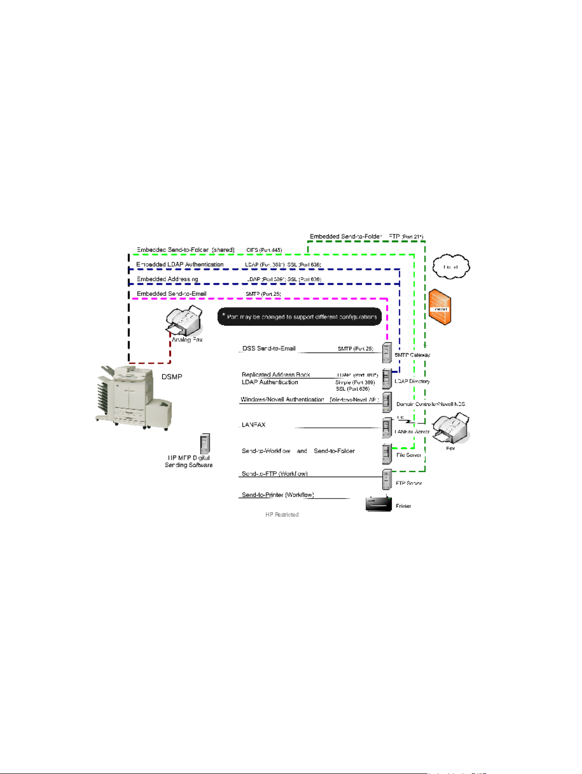
Figure 1-1 Embedded and service-based Digital Sending
Differences
The following product groups are represented in the Features Comparison table below.
Group 1 — HP LaserJet 4100 and 9000 MFP
●
Group 2
●
HP LaserJet 4345, 9040/9050, M3035, M4345, M5035 and M9040/9050 MFP
◦
◦ HP Color LaserJet 4730, 9500, CM3530, CM4730 and CM6030/6040 MFP
◦ HP 9200c and 9250c Digital Sender
6 Chapter 1 Introduction to Digital Sending ENWW
Page 15

● Group 3
◦ HP ScanJet Enterprise 7000n Document Capture Workstation
HP M4555 MFP and CM4540 Color MFP
◦
Group 4 — HP LaserJet 9055 / 9065 MFP
●
Group 5 — HP CM8050/8060 Color MFP
●
Table 1-1 Feature comparison
Area Feature Product Groups
Group 1 Group 2 Group 3 Group 4 Group 5
Authentication LDAP NA NA
LDAP over SSL NA NA
Microsoft Windows DSS DSS DSS
Kerberos NA E E NA E
Novell Netware DSS DSS
Send to E-mail DSS
Folder NA NA
LAN Fax DSS DSS NA
Internet Fax DSS DSS NA
Analog Fax E E E** NA E
Printer DSS DSS
Addressing Direct LDAP
Replicated LDAP DSS DSS NA
Public Address Book DSS DSS DSS DSS
Personal Address Books DSS DSS
Exchange Contacts DSS DSS DSS
Local Address Book E E DSS
**
DSS
DSS NA
NA
DSS
ENWW Embedded Digital Sending vs DSS 7
Page 16

Table 1-1 Feature comparison (continued)
Area Feature Product Groups
Group 1 Group 2 Group 3 Group 4 Group 5
Other Optical Character Recognition (OCR) DSS DSS DSS*** DSS
Workflow DSS DSS DSS DSS* DSS
Metadata support DSS
Custom-keys metadata DSS DSS DSS NA DSS
FileNet integration DSS DSS DSS DSS DSS
Single point for e-mail routing DSS DSS DSS DSS NA
SMTP gateway redundancy DSS DSS DSS DSS DSS
SMTP over SSL DSS DSS
Quick Sets NA NA
PDF/A DSS DSS
Compact PDF DSS DSS
Signed e-mail NA NA
Encrypted E-mail (message) NA NA
Legend
● DSS — Requires DSS
●
— Available both embedded and when managed by DSS
NA
DSS DSS
NA NA
NA
● E — Available only in embedded Digital Sending
● NA — Not available
● * — Appended: limitations apply
● ** — Not available on the HP ScanJet Enterprise 7000n Document Capture Workstation.
● *** — The HP ScanJet Enterprise 7000n Document Capture Workstation has this feature
available both embedded and when managed by DSS.
Advantages of DSS
HP Digital Sending Software allows customers to do the following:
Table 1-2 What else does DSS allow you to do?
Feature Benefits
Send to LAN Fax and Internet Fax Allows sending faxes through LAN Fax and Internet Fax
8 Chapter 1 Introduction to Digital Sending ENWW
systems from DSS-enabled devices using the Fax icon,
which offers a user-friendly interface with Speed Dials,
address book etc.
Page 17

Table 1-2 What else does DSS allow you to do? (continued)
Feature Benefits
Public Address Book Allows an administrator to maintain an address book which is
Personal Address Books Gives each user of the DSS-enabled device a personal
Microsoft® Exchange Contacts Gives the user access to his/her Exchange Contacts within
LDAP Replication Offers a way to allow DSS-enabled devices to access the
Address Book Manager Allows an administrator to manage the contents of DSS
Send to E-mail With DSS the Send to E-mail jobs from connected devices
Optical Character Recognition (OCR) Allows scanning to searchable text formats, such as PDF,
accessible to all devices connected to the DSS server.
address book, which is accessible from any device
connected to the DSS server.
Users can manage the contents of their personal address
book from the front panel of the device.
the e-mail- and fax address book of the device.
content of an LDAP address book through DSS. As the
replication occurs at a schedule set by the administrator this
feature can off-load the LDAP servers.
address books.
can be routed through DSS. This provides the following
benefits:
● Allows scanning to e-mail in environments with strict
SMTP security with minimal management effort.
● Supports several SMTP gateways for redundancy.
XPS and RTF.
Device Management Allows management of Digital Sending features on the entire
fleet of DSS-enabled device from a user-friendly interface.
ENWW Embedded Digital Sending vs DSS 9
Page 18

DSS vs Web Jetadmin
HP Digital Sending Software and HP Web Jetadmin are two different software products available
from HP with very different value propositions. However, while the products are different there is still
some overlap in functionality. The purpose of this section is to provide a basic understanding of the
differences between DSS and HP Web Jetadmin.
HP Web Jetadmin is a fleet management tool designed to manage printers and Digital Sendingenabled devices on a network. Features include device configuration, firmware installation, remote
diagnostics, alerting and reporting - to name a few. For instance, system administrators can use this
tool to get alerts for specific error conditions, update firmware on the entire fleet of devices and create
usage reports.
HP Digital Sending Software extends the embedded Digital Sending features of supported devices
with features such as LAN Fax, OCR, Workflows and Personal Address Books. Where DSS may
appear to overlap somewhat with Web Jetadmin is in that it also manages the Digital Sending
settings for connected devices. In fact, when a device is connected to DSS it is only possible to
manage the Digital Sending settings using the DSS Configuration Utility. Web Jetadmin can still be
used to manage all other settings on the device. For more information on the values and capabilities
of DSS, please refer to other sections of this document.
10 Chapter 1 Introduction to Digital Sending ENWW
Page 19

What is new in DSS 4.91?
With the release of DSS 4.91, several improvements have been made. DSS 4.91 provides the
functionality of DSS 4.x on a new .NET platform and also adds support for DSS-enabled devices
using the new HP firmware base code.
Table 1-3 Product improvements in DSS 4.91
Component Description
Adds support for Windows 2008, Windows 7 and Windows Vista.
●
Operating system
support
Product compatibility
Configuration Utility
OCR engine
Send to E-mail Secure e-mail channel (SMTP over TLS/SSL).
File types
● Supported on R2 and 64-bit versions of these operating systems, but runs in 32-bit (x86)
mode.
Supports the HP ScanJet Enterprise 7000n Document Capture Workstation.
●
● Supports Digital Sending-enabled devices based on the new HP firmware code, starting with
the HP M4555 MFP and CM4540 Color MFP.
● Configuration Utility window can be maximized and stretched
Supports simultaneous use by multiple administrators.
●
● Faster Configuration Utility start time as device status is only updated when selected by
administrator.
Device grouping.
●
● Miscellaneous UI improvements, such as progress bars.
● Updated to I.R.I.S. engine version.
● Improved text recognition.
● Improved performance and scalability.
● PDF/A – Supporting PDF/A allows customers to meet ISO standards for long-term archival of
electronic documents.
● Compact PDF (high compression of PDF files).
● Exchange Contacts now via HTTPS. MAPI client no longer required.
Addressing
Replaced outdated
functionality
● Address Book Manager now integrated within the Configuration Utility.
Multiple device configuration and copy/paste for device configuration replaced with templates.
●
● Secondary e-mail replaced with SMTP over SSL.
● Novell Bindery no longer supported for authentication.
Windows Fax Service no longer supported.
●
ENWW What is new in DSS 4.91? 11
Page 20

12 Chapter 1 Introduction to Digital Sending ENWW
Page 21

2 Theory of operations
This chapter contains the following topics:
Components
●
●
Understand licensing
ENWW 13
Page 22
Components
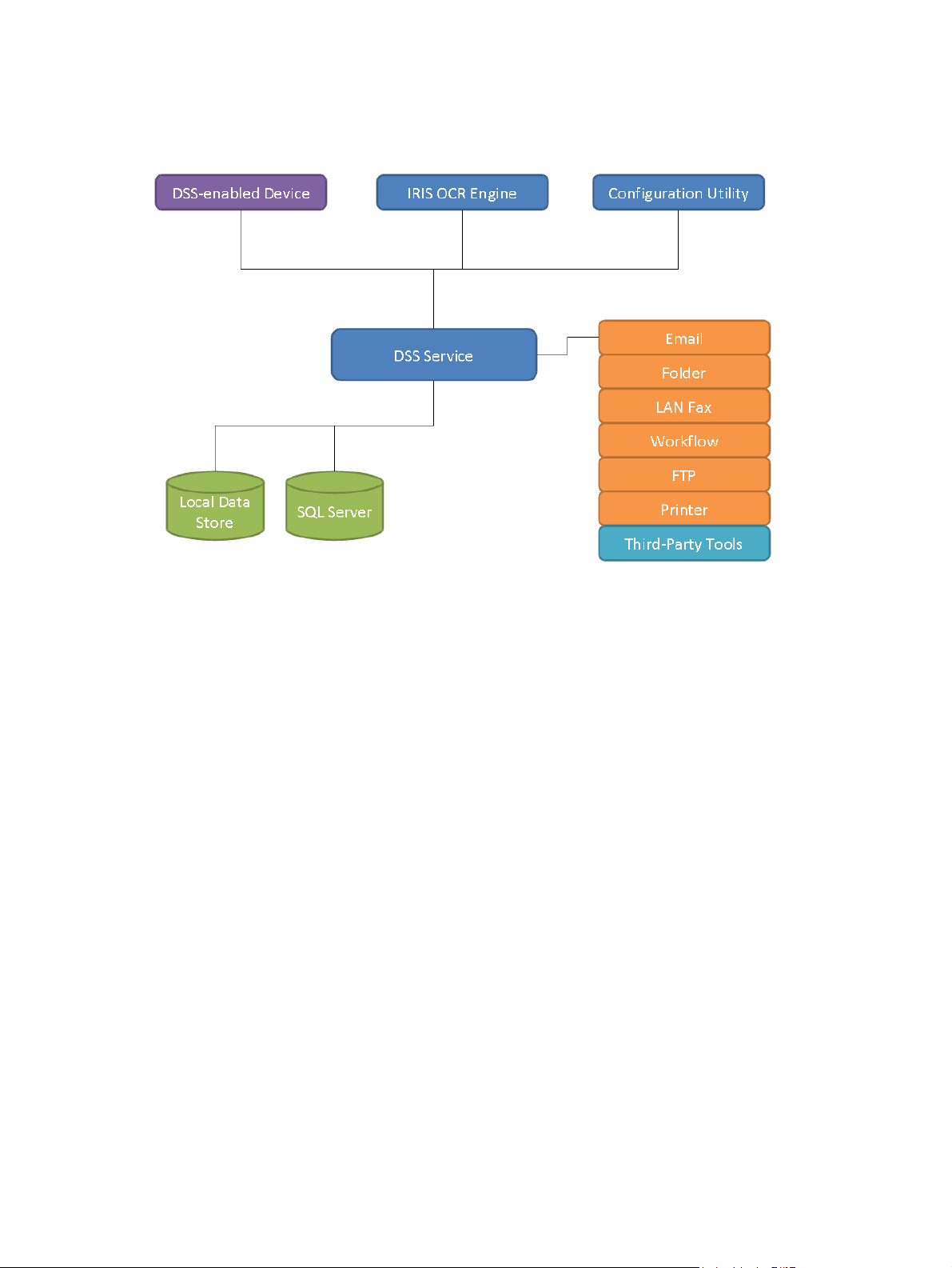
Figure 2-1 DSS Components
DSS can be viewed as a system that consists of a number of components, where each component
provides a specific set of features that allows the system to function as a whole. The above diagram
shows the DSS components and how they are connected. The following covers each of these in
detail.
DSS Service
the central nervous system of the HP Digital Sending Software is the service named "HP Digital
Sending Software", typically called the "DSS service". This is the key component of the software that
ties together all other components and enables the DSS system to function.
14 Chapter 2 Theory of operations ENWW
Page 23
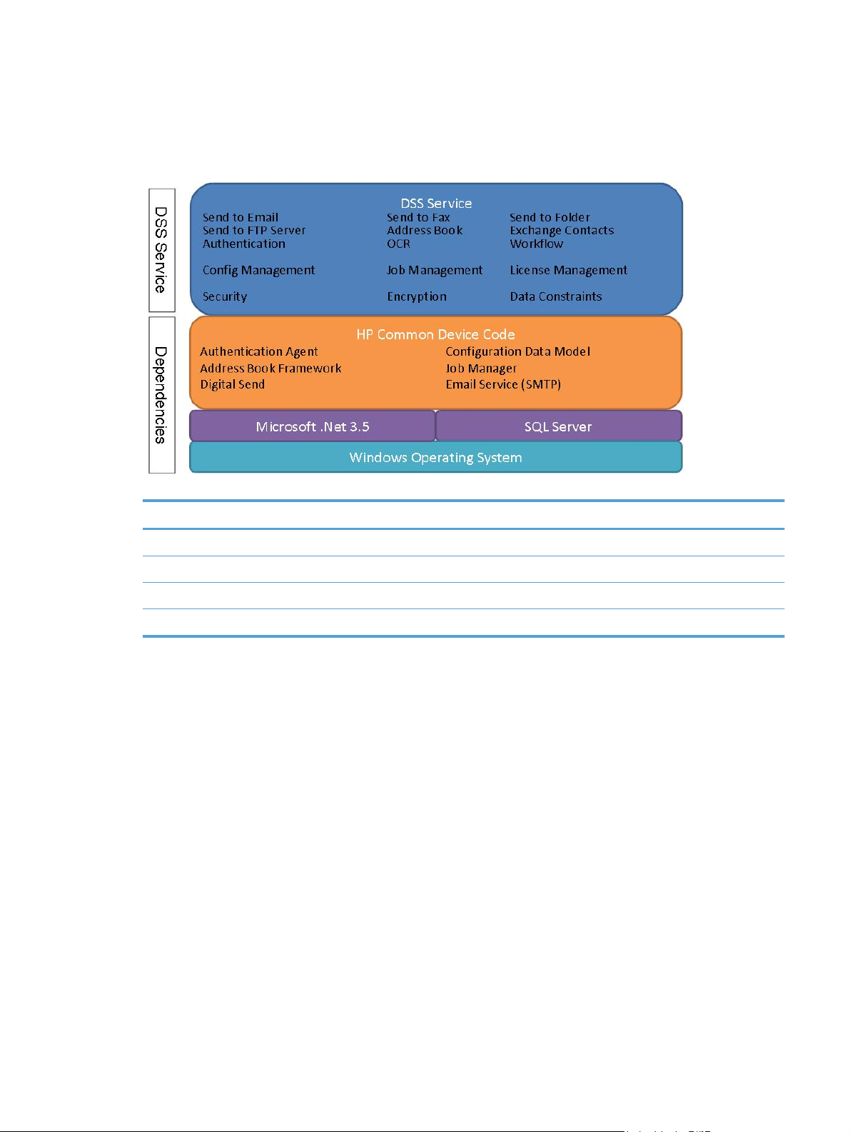
Internally, the DSS service is divided into several subcomponents and has dependencies. The below
figure shows this at a high level:
Figure 2-2 DSS Service Architecture
Table 2-1 DSS Service – Technical Detail
Technical detail
Service display name: HP Digital Sending Software
Service name: DssWinService
Executable name: HP.Dss.App.WinService.exe
Typical memory usage: 200-400MB
Configuration Utility
The role of the Configuration Utility is to act as a management console for DSS. It provides a user
friendly interface to manage all settings for DSS functions as well as devices.
The Configuration Utility is always installed with DSS, but can also be installed separately on a
different computer on the network. When installed separately it is typically referred to as the "Remote
ENWW Components 15
Page 24
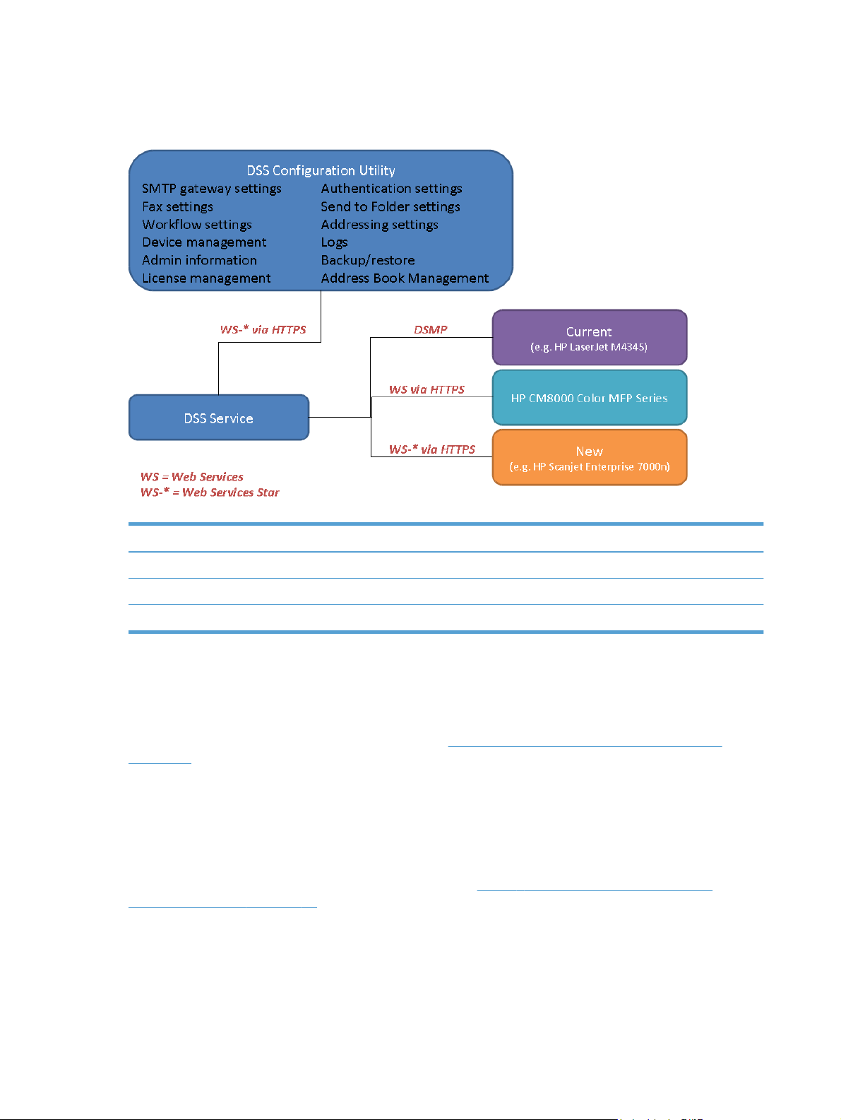
Configuration Utility", since in this mode it is used to manage a remote DSS server. The address of
the server to be managed is entered in the startup dialog.
Figure 2-3 Configuration Utility
Table 2-2 Configuration Utility– Technical Detail
Technical detail
Executable name: HP.Dss.App.ConfigurationUtility.View.exe
Default window size: 1024x768
Typical memory usage: 200-300MB
DSS-enabled device
DSS-enabled devices are the HP MFPs, Digital Senders or ScanJet products that support DSS.
These devices allow end-users to make use of DSS functionality by scanning to the various
destination types, using the address book etc. See
on page 5 for a complete list of supported devices.
The firmware in these devices has a component built-in which enables use of DSS functionality. In
the previous generation products this is enabled through DSMP (Digital Sending Management
Protocol). In HP's latest generation products this component has been replaced by a WS-* (Web
Services Star) based interface.
Since all DSS features have to be supported by the device firmware DSS 4.91 has a minimum
firmware version requirement, which can be found here
firmware revisions on page 25. Over time, as new features become available in DSS, it may be
required to update the device firmware for compatibility. These changes will be documented in detail
in the DSS release notes.
Supported devices – Legacy device support
Table 3-3 DSS 4.91 supported device
16 Chapter 2 Theory of operations ENWW
Page 25
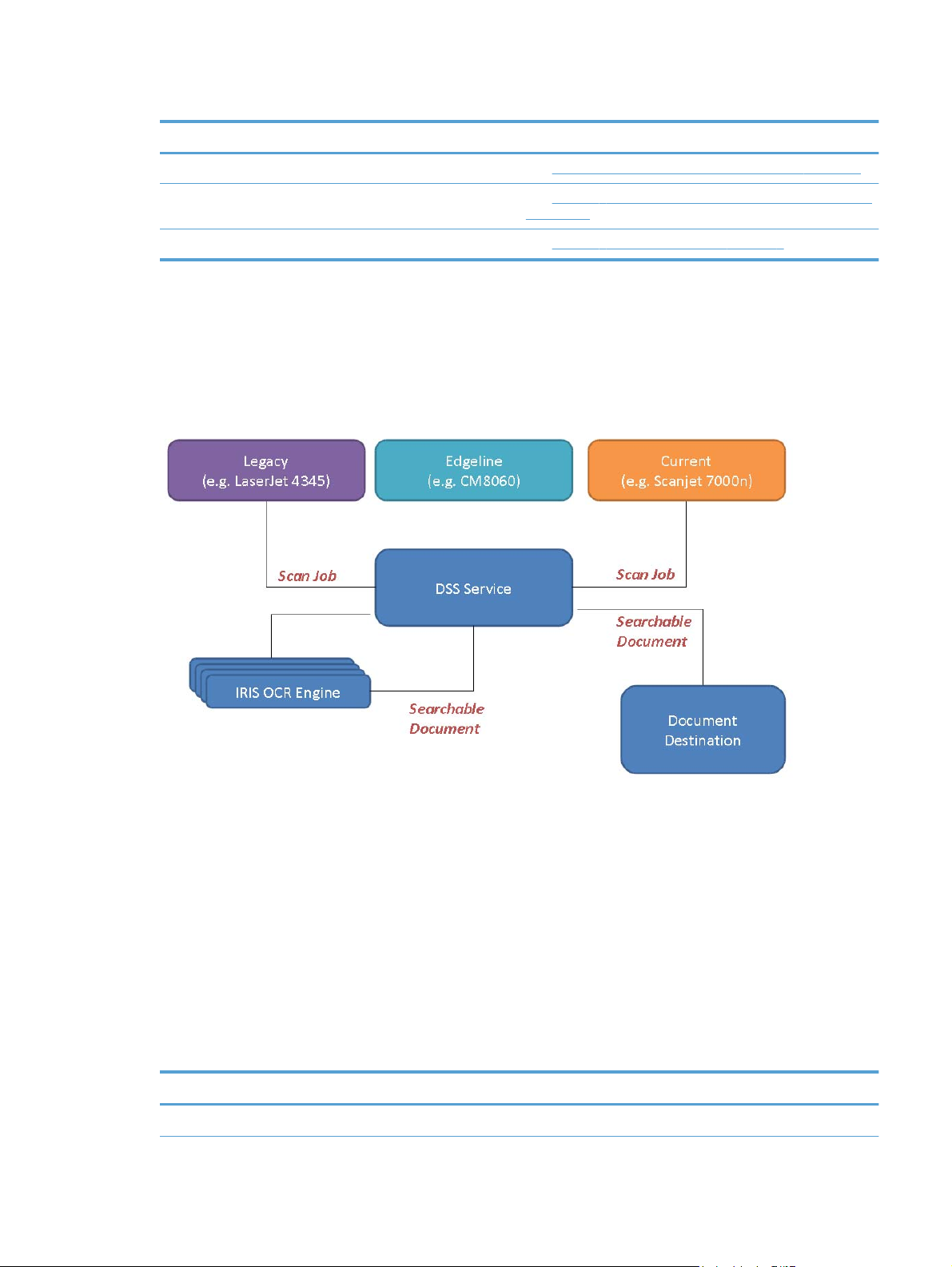
Table 2-3 DSS-enabled devices – Technical Detail
Technical detail
List of supported devices: See
Minimum firmware version: See
Feature matrix: See
I.R.I.S. OCR engine
DSS uses I.R.I.S. OCR engine version 12 to provide Optical Character Recognition (OCR) and High
Compression PDF functionality. The engine features Intelligent High Quality Compression (iHQC)
technology™.
Figure 2-4 OCR engine
Supported devices – Legacy device support on page 5
Table 3-3 DSS 4.91 supported device firmware revisions
on page 25
Table 1-1 Feature comparison on page 7.
The figure above shows how the process flow OCR processing in DSS. When DSS receives a job
where OCR processing is required it invokes the I.R.I.S. OCR engine using COM (Component Object
Model). The image data/document is transferred together with control parameters, such as the
required output file type. Once OCR processing is completed the searchable document is passed
back to DSS which delivers the document to the destination.
DSS is a multi-threaded application and will launch multiple instances of the OCR engine when there
are multiple jobs in the queue that require OCR processing. We refer to this as ‘parallel processing of
OCR jobs’. This makes the OCR feature scalable, which means that average job processing times
will be improved if the server's resources are improved. For instance, adding additional CPUs and
more memory to the server will improve the average processing time of each OCR job when the
server is processing multiple jobs simultaneously. This is a significant improvement over previous
versions of DSS, where OCR processing was serial.
Table 2-4 I.R.I.S. OCR engine – Technical Detail
Technical detail
OCR engine: I.R.I.S. OCR engine version 12
ENWW Components 17
Page 26

Table 2-4 I.R.I.S. OCR engine – Technical Detail (continued)
Technical detail
Default install directory: C:\Program Files\DsOcrComSrvr
Executable name: dpe_ocr123.exe
Languages supported: I.R.I.S OCR 12 recognizes more than 120 languages
Database
DSS uses Microsoft SQL Server 2005 Express Edition to host the DSS database. The database is
used to hold the DSS activity log.
Table 2-5 Database – Technical Detail
Technical detail
Database name: HPDSS
Access security: Windows Integrated Security
Local Data Store
The Local Data Store is the series of files located in the DSS installation directory, which is used to
store the DSS configuration data, device information and debug logs. This is also where the job
queue resides.
Table 2-6 Local Data Store – Technical Detail
Technical detail
Default installation dir: C:\Program Files\Hewlett-Packard\HP Digital Sending
Job queue dir: .\ Filesystems\CustomerData\DSS\Jobs
Configuration dir: . \Filesystems\Product\DSS\Configuration
Third-party tools
As the name indicates, third party tools are not a part of the DSS system. However, they are
mentioned here because third party tools are required to deliver some of the DSS functionality as
listed here:
LAN Fax. This feature requires a compatible LAN Fax product. DSS enables the functionality by
●
providing a Fax interface at the Digital Sending-device and then passing the fax job along with
an HPF file (metadata) to a watched folder.
Internet Fax. This feature requires an Internet Fax server. DSS enables the functionality by
●
providing a Fax interface at the Digital Sending-device and then sending out an e-mail with the
fax job attached.
Software 4.91
Workflow. One of the main ideas behind the Workflow feature is the ability to capture metadata
●
at the Digital Sending-device and pass it on to a folder that is watched by a third party
18 Chapter 2 Theory of operations ENWW
Page 27
application. This application is then able to read the metadata and further process and route the
job.
● Personal Address Book. This feature requires a Microsoft Exchange Server that supports
HTTP connections.
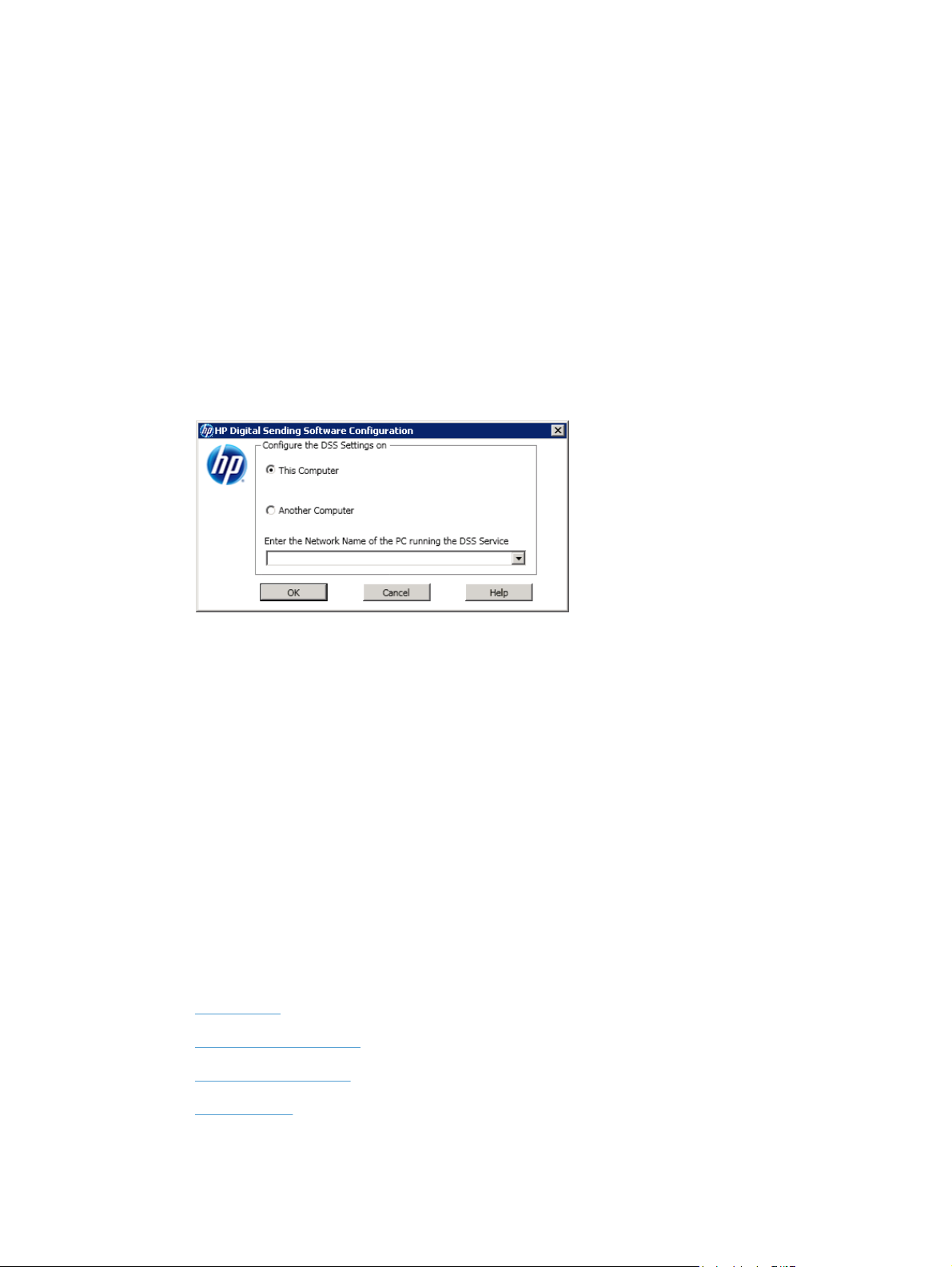
Remote Configuration Utility
The Remote Configuration Utility is a version of the Configuration Utility that is designed to install and
operate on a remote computer.
Using the Remote Configuration Utility allows DSS configuration across the network.
1. Launch the Configuration Utility.
2. Click Another Computer.
Figure 2-5 Remote Configuration Utility
3. Type in the network name of the DSS server.
4. Click OK.
Device firmware
DSS-enabled devices are "DSS aware," meaning they have components built into the firmware that
allow them to make use of the services and features offered by DSS. Some DSS features require a
minimum firmware level; therefore, the version of firmware loaded on the DSS-enabled device is
important.
For example, the OCR processing feature for Send to E-mail requires a minimum firmware revision of
48.051.1 to work on the HP LaserJet M5035 MFP. If the firmware revision is not at least 48.051.1, the
OCR processing feature for DSS Send to E-mail cannot function.
Understand licensing
This section contains the following topics:
Trial license
●
Licensing requirements
●
Auto-generate license
●
Node Locking
●
ENWW Understand licensing 19
Page 28

Trial license
When DSS is installed for the first time, you have the option of entering a license number or using the
software on a 60-day evaluation basis. During the evaluation period, the software can support up to
50 Digital Sending-enabled devices. When the trial period expires, the software becomes inactive
until a license is installed.
Licensing requirements
The Licenses section of the Configuration Utility General tab contains a Trial License entry where
new licenses must be added. The remaining trial period also appears on that tab.
DSS is available in five different seat configurations.
Seats Part Number
1 T1936AA#UA0
5 T1936AA#0AD
10 T1936AA#0A9
50 T1936AA#0AA
250 T1936AA#UD6
Each seat enables Digital Sending features on one device. As many licenses as needed can be
installed to in order to accumulate seats.
Click Add on the General tab to type a new license key code for the HP Digital Sending Software.
Auto-generate license
The HP 9200C Digital Sender and HP 9250C Digital Sender devices auto-generate licenses after
being added to an existing licensed DSS server. These are the only two DSS-enabled devices that
auto-generate licenses.
Node Locking
Purchased licenses can be applied only to a specific DSS server. The node-locking process
combines the license certificate with a unique ID from the DSS server. The unique ID appears on the
About tab of the Configuration Utility as the MAC Address. This ID appears during and after the trial
period. To activate the license certificate, record the MAC Address that appears on the About tab of
the Configuration Utility and proceed to the HP Software License Manager Website at
licensing.hp.com. At this Website, type the license certificate number and the MAC address. The
Software License Manager activates licenses based on information located on the purchased license
20 Chapter 2 Theory of operations ENWW
Page 29
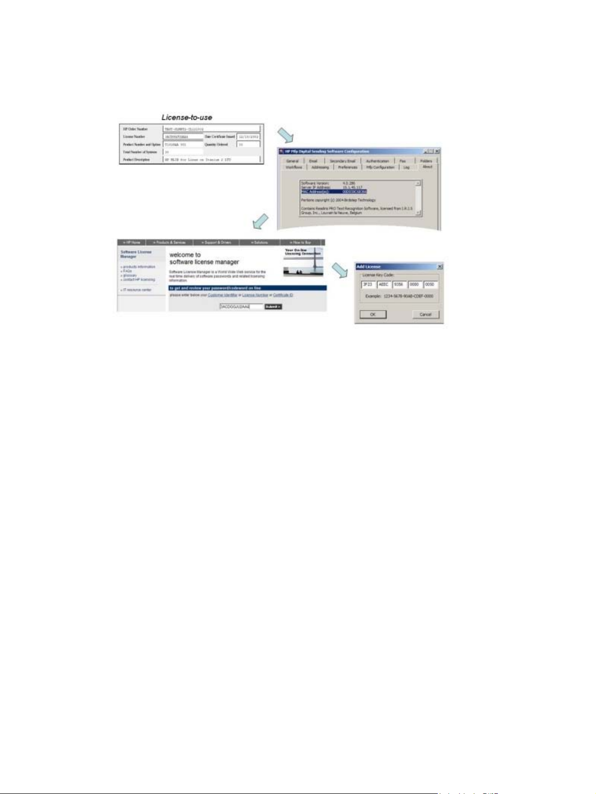
certificate(s) and the server ID of the DSS server. After this information is entered into the Software
License Manager, the generated licenses are delivered by fax or e-mail.
Figure 2-6 License Node Locking
ENWW Understand licensing 21
Page 30

22 Chapter 2 Theory of operations ENWW
Page 31

3 Installation and configuration
This chapter contains the following topics:
Planning the DSS deployment
●
●
Installation
Configuration
●
ENWW 23
Page 32

Planning the DSS deployment
This section contains the following topics:
System and environment requirements
●
Backup and restore strategy
●
Licensing
●
Device differences
●
System and environment requirements
This section contains the following topics:
Software requirements
●
Hardware requirements
●
Port requirements
●
Software requirements
The following table shows the server software requirements.
Table 3-1 DSS software requirements
Area Requirements
Operating systems
Virtual servers
Miscellaneous .NET Framework 3.5
Novell
Hardware requirements
Microsoft Windows XP
●
● Microsoft Windows Vista
● Microsoft Windows 7
● Microsoft Windows Server 2003, including R2
● Microsoft Windows Server 2008, including R2
NOTE: 64-bit operating systems are supported, but DSS runs in 32-bit mode
VMware ESX 3.5 and later
●
● Microsoft Virtual Server 2005 and later
● Microsoft HyperV
Novell Netware 5 or higher
●
● Novell Client 4.91 or higher for Windows XP/2003
● Novell Client 2 or higher for Windows Vista/7/2008
The following table shows the server hardware requirements.
24 Chapter 3 Installation and configuration ENWW
Page 33

Table 3-2 DSS hardware requirements
Type Minimum Recommended Recommended for
Processor
Memory See operating system
Page file n/a See operating system
Disk free space n/a 400 MB on the drive
Screen resolution n/a 1024 x 768 pixels Larger than 1024 x
Network link Ethernet 100 MB 1 GB 1 GB
Network link NTFS n/a n/a n/a
Virtual server
See operating system
documentation. 1 GHz 2 GHz 2 GHz, dual core
documentation.
VMware ESX 3.5 and later
●
● Microsoft Virtual Server 2005 and later
1 GB of RAM 1 GB of RAM per
documentation.
where you install DSS
(this is where jobs are
spooled). 200 MB on
the drive where you
install the database.
server plus 3 MB per
device.
See operating system
documentation.
1 GB on the drive
where you install DSS
(this is where jobs are
spooled). 1 GB on the
drive where you install
the database.
768
1000 devices
4 GB
See operating system
documentation.
2 GB on the drive
where you install DSS.
2 GB for the database.
Larger than 1024 x
768
NOTE: Minimum requirement must be reserved on virtual servers.
Actual requirements vary depending on number of devices managed, features enabled and usage
load. Note that heavy usage of OCR may have a significant impact on server performance.
Device firmware requirements
To support DSS features, some devices require a minimum revision of firmware. Over time, as new
features become available in DSS, it may be required to update the device firmware for compatibility.
These changes will be documented in detail in the DSS release notes.
Table 3-3 DSS 4.91 supported device firmware revisions
Device model Minimum firmware revision
HP LaserJet 4100 and 9000 MFP 03.804.6
HP LaserJet 4345mfp 09.111.1
HP LaserJet 9040 / 9050 MFP 08.101.9
HP LaserJet 9055 / 9065 MFP 07.006.7, and requires the DSS JAR file version 4.0.0.0 to be
HP Color LaserJet 9500mfp 08.101.9
● Microsoft HyperV
installed. Contact HP support if an update is required.
HP Color LaserJet 4730mfp 46.191.2
HP LaserJet M3035mfp 48.051.1
ENWW Planning the DSS deployment 25
Page 34

Table 3-3 DSS 4.91 supported device firmware revisions (continued)
Device model Minimum firmware revision
HP LaserJet M4345mfp 48.051.1
HP LaserJet M5035mfp 48.051.1
HP 9200c Digital Sender 09.111.1
HP 9250c Digital Sender 48.041.1
HP Color LaserJet CM3530 MFP Any
HP Color LaserJet CM4730mfp 50.031.0
HP Color LaserJet CM6030 / CM6040 MFP Any
HP CM8050 / CM8060 Color MFP with Edgeline Technology Any
HP LaserJet M4555 MFP Releases fall of 2010
HP CM4540 Color MFP Releases fall of 2010
HP ScanJet Enterprise 7000n Document Capture
Workstation
Releases fall of 2010
26 Chapter 3 Installation and configuration ENWW
Page 35

Port requirements
DSS 4.91 uses a number of industry standard network protocols and their corresponding TCP and
UDP ports in order to facilitate its Digital Sending functionality, such as Send to E-mail, Send To
Folder, Authentication, and LDAP Replication. This section gives an overview of which ports are used
in different configurations.
In its most basic configuration, DSS 4.91 requires ports 1783, 5213, 7627 and 161 to function. At
install time DSS will register itself with the desktop firewall to ensure connections are allowed on
these ports. Administrators may refer to the table in this section to determine which ports are required
for their specific configuration of DSS 4.91.
Ports used
DSS uses the TCP/IP protocol to communicate on the network. Which TCP or UDP ports are used
depends on which features are enabled in DSS 4.91 and which underlying protocols facilitate these
features. Also, note that for each protocol DSS acts as a server or client, or both. The following table
provides an overview. Administrators should ensure that the required ports are open at appropriate
points in the network, for example, desktop firewall, switches and routers.
Table 3-4 Ports used by DSS 4.91
Feature Type Protocol Port Role of DSS Can it be
Device
communication for
current and legacy
devices
WS-* (WS-STAR),
used for device
communication for
latest generation
devices and for
communication
between DSS and
the Configuration
Utility
Device discovery
and configuration
E-mail
notifications,
e-mail via service
Send to Folder
(Network UNC
2
path)
Send to FTP Optional FTP 21 (TCP) Client No
Required DSMP
Required HTTPS 7627 (TCP) Server & client No
Required SNMP 161 (UDP) Client No
1
Optional
Optional CIFS / SMB 445 (TCP) Client No
(HP Proprietary)
SMTP 25 (TCP) Client Yes
1783 (TCP) Server & client No
changed?
LDAP Replication
& Authentication,
simple bind
LDAP Replication
& Authentication,
simple over SSL
bind
Optional LDAP 389 (TCP) Client Yes
Optional LDAP 636 (TCP) Client Yes
ENWW Planning the DSS deployment 27
Page 36

Table 3-4 Ports used by DSS 4.91 (continued)
Feature Type Protocol Port Role of DSS Can it be
changed?
LDAP Replication
& Authentication
SPNEGO
LDAP Replication
& Authentication,
Global Catalog
DSS Address Book access for latest generation devices
1
If a mail gateway is not required, enter a dummy address (0.0.0.0) in the Configuration Utility.
2
Does not apply to local folders, for example. c:\myfolder.
3
If another application is using 5213, a configuration file is available to override this port number.
Optional Kerberos 88 (TCP) Client No
Optional LDAP 3268 (TCP) Client Yes
Required Secure SQL
DSS Address Book access for latest generation devices
HP's latest generation devices, starting with the HP ScanJet Enterprise 7000n Document Capture
Workstation, HP M4555 MFP and HP Color CM4540 MFP, now access the DSS Address Book by
connecting directly to the SQL database (which is running on the same server as DSS).
Hostname resolution
DSS 4.91 supports the use of hostnames for server addresses. Depending on the configuration of the
host machine, DSS 4.91 will use NetBIOS/WINS (port: 137, 138 or 139)) or DNS (port: 53) for
hostname resolution.
5213
3
Server No
Backup and restore strategy
This section contains the following topics:
Understand DSS data structures
●
Software capabilities for backup and restore
●
Scaling the DSS server
●
Understand DSS data structures
This section aims to provide an understanding of what data DSS manages in order to help customers
develop a sound backup and restore strategy. The following describes the different types of data that
makes up the DSS system and where it is stored.
Table 3-5 DSS data
Component Location Description
Job logs Database Job logs for all devices are stored in the
Error logs Database and Windows Event Log The error logs show system events for
DSS database.
information, warning and error
conditions such as service stop and
security audit.
28 Chapter 3 Installation and configuration ENWW
Page 37

Table 3-5 DSS data (continued)
Component Location Description
Debug logs [Install Path]\FileSystems\MachineData
DSS configuration settings [Install Path]\FileSystems\Product\DSS
Device information DSS maintains a list of all the devices it
Device configuration settings Stored on the device All the device-specific configuration
Configuration Utility UI ‘convenience’
data
\Logs
\Configuration
Windows Registry For usability the DSS Configuration
DSS maintains a set of debug log files.
These files are designed to help HP
support debug issues with the DSS
service, such as crashes, hangs etc.
Configuration data used by DSS is
stored in a series of files found in the
Configuration folder. This data includes
things like SMTP gateway settings,
LDAP addressing settings, Workflow
settings etc.
manages in a binary configuration file.
This file also contains some basic
information about the device, such as
the hostname, device model etc.
data is stored on the device itself. When
required DSS will read back the data
from the device, manipulate it and send
it back.
Utility will remember entries made into
selected list boxes, as well as the state
of the Configuration Utility window when
closed.
Software capabilities for backup and restore
DSS features a backup and restore feature to allow for easy backup and restore of DSS data.
Back up DSS data
1. Open the DSS Configuration Utility.
2. On the General tab, click Backup. The Backup DSS Settings dialog box appears.
3. Navigate to the location where you want to save the backup file, and then click Save.
Restore DSS data
1. Open the DSS Configuration Utility.
2. On the General tab, click Restore. The Open dialog box appears.
3. Navigate to the location where you saved the backup file, click to select the file, and then click
Open.
Scaling the DSS server
Correctly scaling/sizing a DSS server is a complex task which should include industry standard tools
and methods. This section provides information specific to DSS to assist in the scaling process, but is
not a complete reference.
ENWW Planning the DSS deployment 29
Page 38

Limitations
There is no hard limit to how many devices can be added to the server, but HP will support up to
1000 devices per server with DSS 4.91. Note that this limit may change in the future, so make sure to
read the release notes when updates are available and look for information on the HP Website at:
www.hp.com/go/dss.
Features and factors that limit scalability
Most features offered by DSS are fairly lightweight in terms of server processing, with the exception
of the following.
Optical Character Recognition (OCR)
●
High compression PDF
●
LAN fax with notification support
●
Other factors that limit scalability include the following.
Utilization/scan job volume
●
Routing jobs through DSS
●
Very large DSS address books
●
Complex workflow design
●
Recommendations
Given the factors stated above, DSS administrators should consider the following approaches to
improving the scalability of DSS:
Limit OCR to specific workflows.
●
Configure devices to send e-mail directly via the SMTP gateway, rather than via DSS.
●
Configure devices to use direct LDAP address book.
●
Use the notification features of the LAN Fax server.
●
For OCR intensive environments, use high performance servers and use multiple servers to
●
divide the load.
It is recommended to perform a pilot test of a given DSS configuration prior to wide scale roll-out.
During the pilot administrators should make sure to test all the required DSS features on a limited
number of devices while using the Windows performance monitoring tools to assess the impact on
server performance.
Licensing
In order to use the features of this version of the DSS, you must purchase and install at least one
device license. These licenses come in bundles of 1, 5, 10, 50 and 250 device licenses (device
licenses are sometimes also referred to as "license seats").
Each seat allows you to enable DSS features on one DSS-enabled device. Adding licenses is
cumulative and there is no limit to the number of license seats you can add to one server. See
the DSS server on page 29 for information about how to scale the DSS server.
30 Chapter 3 Installation and configuration ENWW
Scaling
Page 39

Activating licenses
To prevent misuse DSS licenses are protected by node locking technology. This means that licenses
need to be activated before they can be used. Activation occurs by registering the license on the
HP Software License Manager site:
To register the license the following information is required:
● The License Number found on the Software License Certificate.
Figure 3-1 DSS License Certificate
licensing.hp.com.
● The MAC address of the server where DSS is installed (you can find this information in the
About tab of the DSS Configuration Utility).
● Your contact information.
After entering this information into the Software License Manager an activated license key is
generated and delivered to the screen, and via fax or e-mail.
ENWW Planning the DSS deployment 31
Page 40

Install licenses
The activated license key is in the format XXXX-XXXX-XXXX-XXXX-XXXX. The key is entered in the
General tab for the Configuration Utility, which will then show the number of seats provided by each
license key, as well as the total accumulated number of seats.
Figure 3-2 Install licenses
Trial or demo license
When DSS 4.91 is installed for the first time, the software is fully functional in trial mode, supporting
50 devices for 60 days. The License section of the DSS Configuration Utility displays a "Trial License"
message and the time remaining in the trial period. The trial license period cannot be extended. Once
the trial license expires, customers must install a valid license to continue using DSS.
Upgrading from previous products
Licenses from DSS 3.0 and earlier revisions of DSS 4.x are fully functional in DSS 4.91. For DSS 3.0
it is required to manually enter each license key into the General tab in the Configuration Utility. For
earlier revisions of DSS 4.x the licenses are carried over through the backup/restore feature.
Node locking
DSS licenses are protected by node locking. For more information, see the Node Locking on page 20
section of this guide.
32 Chapter 3 Installation and configuration ENWW
Page 41

Device differences
As part of planning the deployment of a DSS server it is important to understand the Digital Sending
features available in the various device models in the environment. See
comparison on page 7 for more information.
Table 1-1 Feature
ENWW Planning the DSS deployment 33
Page 42

Installation
This section contains the following topics:
Pre-installation checklist
●
Installer screens and options
●
Pre-installation checklist
1. Review the hardware and software requirements for the DSS server. See System and
environment requirements on page 24 for more information.
2. Verify that devices planned for connection to DSS have the minimum required firmware.
3. If you are upgrading from a previous version of DSS, make a backup of the existing
configuration.
4. The MAC address of the server that will host the DSS service.
Installer screens and options
Follow these steps to install the HP Digital Sending Software 4.91.
1. After downloading the software to your computer or network, close all programs that are open on
the computer.
2. Navigate to the location on the computer or network where you downloaded the HP Digital
Sending Software 4.91 software, and double-click the setup.exe file.
34 Chapter 3 Installation and configuration ENWW
Page 43

3. The Welcome screen appears. Click Next to continue.
Figure 3-3 Software Installation – Welcome screen
4. The License Agreement screen appears. Click Print to print a copy of the license agreement.
Click I do not accept the terms in the license agreement, and then click Next to cancel the
installation.
After reading the license agreement, click to select I accept the terms in the license
agreement, and then click Next to continue the installation.
5. The Windows Firewall Configuration screen appears. Click to select the Allow this service to
accept incoming network requests. check box, and then click Next to continue.
6. The Destination Folder screen appears. Click Browse to select a different destination folder.
Click Full Installation or Configuration Utility Only, and then click Next to continue.
7. The Ready to Install the Program screen appears. Click Back to go back to change installation
options. Click Install to start the installation.
8. The Microsoft SQL Server 2005 Setup Progress screen displays the installation progress for
the SQL server.
9. The Installing HP Digital Sending Software 4.91 screen shows the progress of the software
installation.
10. When the installation completes, the InstallShield Wizard Completed screen appears. Based
on your configuration and the options installed, a reboot of the DSS server may be required.
Click the Launch HP Digital Sending Software 4.91 check box to launch the software when
the installer closes. Click the Show me the readme file check box if you want to see the product
readme file when the installer closes. Click Finish to complete the installation.
ENWW Installation 35
Page 44

Configuration
The HP Digital Sending Software (DSS) executes as a Windows service and allows users to scan
documents at Digital Sending-enabled devices, and send the scanned images to various types of
destinations (such as e-mail, fax and folder). This software package includes a Configuration Utility
that allows you to set up DSS features in a way that works best in your environment. Each DSS
feature must be configured before it is available for use on Digital Sending-enabled devices.
This section contains the following topics:
Configuration Utility
●
Licensing
●
Device management
●
●
Authentication
General Device configuration
●
Send to Folder
●
Send to E-mail
●
Send to Fax
●
Send to Workflows
●
Addressing
●
Configuration Utility
The Configuration Utility manages settings that apply across all Digital Sending-enabled devices,
such as e-mail server and Authentication method, and also settings that apply to specific devices.
36 Chapter 3 Installation and configuration ENWW
Page 45

The Configuration Utility has several display elements to assist you in knowing what data is required
to make DSS features available on devices.
Figure 3-4 Configuration Utility elements
Table 3-6 Configuration Utility elements
Callout Component Description
1 Exclamation point An exclamation point (!) next to the name of a tab indicates that required
2 Asterisk An asterisk (*) next to the name of a tab indicates that data has been
3 Outline Required data is highlighted with an outline around the necessary setting. In
Licensing
This section contains the following topics:
●
●
●
data for that feature has not been supplied.
entered, but not yet applied. The Apply button must be clicked in order to
save the settings.
this diagram the Name and UNC Folder Path settings are highlighted to
indicate that those are required.
Add licenses
Remove licenses
Auto-generated licenses
ENWW Configuration 37
Page 46

Add licenses
1. In the DSS Configuration Utility, click the General tab.
Figure 3-5 General tab – DSS Configuration Utility
2. In the License Files section, click Add. The Add License dialog box appears.
Figure 3-6 Add License dialog box
3. Type in the 20-digit license key code for the license you are installing, and then click OK.
4. The new license appears in the License Files list and the Total Seats field updates to reflect
the additional seats provided by this license.
38 Chapter 3 Installation and configuration ENWW
Page 47

Remove licenses
In rare instances it is necessary to remove licenses from the DSS server. One condition that would
prompt license removal from a DSS server would be to install those licenses on a new DSS server to
provide hardware redundancy.
1. In the DSS Configuration Utility, click the General tab.
Figure 3-7 General tab – DSS Configuration Utility
2. In the License Files section, click the license you want to remove, and then click Remove.
3. The license is removed from the License Files list and the Total Seats field updates to reflect
the current number of seats provided by any remaining licenses.
NOTE: If by removing a license, your total number of seats falls below the number of Devices
you currently have configured for Digital Sending features, you will be required to remove
Devices from the Device List on the Device Configuration tab to match the number of
remaining sets available.
Auto-generated licenses
The HP LaserJet 9200c and 9250c devices auto-generate a license for use in DSS. This means that
no additional license seat is required for these devices. Once these devices are managed by DSS
they will automatically generate a license that shows up in the DSS Configuration Utility.
ENWW Configuration 39
Page 48

Device management
The Device Configuration tab on the Configuration Utility specifies which devices are using the DSS
service and also provides an interface for customizing DSS features for specific devices.
Figure 3-8 Device Configuration tab
1
2
6
7
3 4 5 8
The Device Configuration tab contains the following elements.
Table 3-7 Device Configuration tab
Callout Component Description
1 Group List Use this list to organize and filter the devices using the DSS service.
● Add Group. Click to create a new group.
Remove Group. Click to remove a group.
●
● Rename. Click to change a group name.
40 Chapter 3 Installation and configuration ENWW
Page 49

Table 3-7 Device Configuration tab (continued)
Callout Component Description
2 Device List This list shows the individual devices using the DSS service as well as the
3 Add Device Click to connect a new device to the DSS service. Once added, the device
4 Remove Device Click to select a device from the list, then click this button to remove the
features that are enabled or not enabled on each device. The Device List
contains the following headings:
● Status
● Name
Authentication icon
●
● Send to E-mail icon
● Fax icon
Send to folder icon
●
● Send to workflows icon
● Addressing icon
Model
●
● Network ID
● Description
will appear in the Device List.
device.
5 Device Sign-in Click this button to configure the device sign-in settings.
6 Total Devices Displays the total number of devices in the Device List.
7 Configure Device Click to select the device you want to configure, then use the sub-tabs to
8 Apply Click this button to save changes made on this tab.
configure DSS features for the selected device.
ENWW Configuration 41
Page 50

Add and remove devices
Add a device
1. On the DSS server, open the Configuration Utility and click the Device Configuration tab.
Figure 3-9 Device Configuration tab
2. Click Add Device. The Add Devices dialog box appears.
Figure 3-10 Add Devices dialog box
3. Click Find Devices to display a list of the DSS-enabled devices on the network.
4. From the displayed list, select the device to be added.
42 Chapter 3 Installation and configuration ENWW
Page 51

NOTE: If you know the hostname or TCP/IP address of the device, you can type it in the
Hostname or IP Address text box under Manually enter a device's network name instead of
using the Find Devices button.
5. Click > to add the device to the Device List.
NOTE: You can add only as many DSS-enabled devices as there are seats available in the
DSS license. The number of seats available appears near the top of the Add Devices dialog
box.
6. Click OK to close the Add Devices dialog box.
Remove a device
1. On the DSS server, open the Configuration Utility and click the Device Configuration tab.
Figure 3-11 Device Configuration tab
ENWW Configuration 43
Page 52

2. In the Device List, click to select the device you want to remove, and then click Remove
Device. The Remove Device dialog box appears.
Figure 3-12 Remove Device dialog box
3. Click Yes (or Yes to All if you are removing multiple devices) to remove DSS-enabled devices.
Device configuration
After adding a new device (or group of devices), use the following procedure to configure the Digital
Sending features for the device or group.
1. On the DSS server, open the Configuration Utility and click the Device Configuration tab.
2. Select a device from the Device List.
3. Click Configure Device. The dialog box that appears looks similar to the main Configuration
program interface. Use this interface to customize the specific Digital Sending settings for this
device.
NOTE: Use this interface to enable the Digital Sending features for the individual devices.
Even if a feature is enabled on the DSS configuration tabs, it is not available on the device until it
has been enabled in the Configure Device interface.
4. On the Authentication tab, click to select the check box for the authentication method you want
to use to enable authentication for the selected device. Select the check boxes next to the
features that are being enabled. Enabling authentication requires the user to log in before using
the selected features. Select the network domain from the Default Domain drop-down menu.
5. On the Send to E-mail tab, select the Enable Send to E-mail check box, and select via the
Digital Sender service in the Send E-mail drop-down list.
Then use the controls in the Address and Message Field Control, Signing and Encryption,
and File Settings sections to customize the Send to E-mail settings for the selected device.
6. On the Addressing tab, select the Enable Network Contacts (use LDAP server) check box if
DSS should retrieve e-mail addresses directly from an LDAP server. Enter the LDAP server
Hostname or IP address, or click the "Auto Find" button. Then enter the LDAP port number
(usually 389).
7. On the Fax tab, select the Enable Fax Send check box to enable the fax feature. Select the
desired fax method in the drop-down menu.
8. On the Send to Folder tab, select the Enable Send to Folder check box to enable this feature.
44 Chapter 3 Installation and configuration ENWW
Page 53

9. On the Send to Workflows tab, select the Enable Send to Workflows check box to enable
workflows and configure settings.
10. Click Apply to save all of the changes.
NOTE: The settings are not propagated to the device until Apply is selected.
Understanding the Device List
The Device List on the Device Configuration tab shows the Digital Sending-enabled devices that
are currently being served by DSS. The icon to the left of the device name indicates the status of the
device.
Table 3-8 Device List icons
Icon Description
Communication with the device is established and the configuration settings are known.
The device configuration has not been retrieved since the Configuration Utility was loaded.
DSS is unable to establish communication with the device and the settings are unknown.
The device was seized by another computer that is running the Configuration Utility. The TCP/
IP address of the other computer is available under the Status heading on the Device List.
To reclaim ownership of a seized device, right-click the crossbones icon and click OK in the
two dialog boxes that appear.
Device grouping
Device grouping is a new feature in DSS 4.91 and provides the ability to organize devices for more
efficient configuration and management.
Figure 3-13 Device grouping
ENWW Configuration 45
Page 54

Create a device group
1. Open the Configuration Utility and click the Device Configuration tab.
2. Select the group in which you want to add a new group or select All Devices. Device groups
can be nested within other groups.
3. Click Add group.
4. Type a name for the new group.
Add devices to a group
1. Right-click on a device and select Add to Group.
2. Click the desired group for this device.
Remove devices from a group
1. Right-click on a device and select Remove.
2. Click Remove from Group.
Authentication
Authentication is a security feature that requires users to provide a network username and password
before using Digital Sending features. Authentication can be turned on or off for each device that the
DSS supports.
NOTE: At no time are the credentials that are used to authenticate at the device written to either the
DSS server or the device hard disk. In addition, although the credentials that the DSS administrator
uses to configure authentication or LDAP addressing are written to the DSS server hard disk, a
hashing algorithm is incorporated to ensure that these credentials cannot be recovered.
Configure DSS
This section contains the following topics:
Authentication methods
●
LDAP bind
●
How to
●
Authentication methods
This section describes the three methods of authentication:
● LDAP authentication
● Windows Active Directory
Novell authentication
●
46 Chapter 3 Installation and configuration ENWW
Page 55

LDAP Server
Figure 3-14 Authentication tab – LDAP Server
1
2
3
The LDAP Server option on the Authentication tab contains the following elements.
Table 3-9 Authentication tab – LDAP Server
Callout Component Description
1 Authentication method Select LDAP Server from the drop-down menu.
2 LDAP Sign In Setup Use the following fields to set up the sign-in method.
LDAP Server address
●
● Port number
● Bind prefix
Bind and Search Root
●
● Match the name entered with this attribute
● Retrieve the device user's e-mail address using this attribute
Retrieve the device user's name using this attribute
●
● Retrieve the device user's group using this attribute
To allow an exact match only, click to select the Exact match on
Group attribute check box.
3 Test LDAP Sign in Type information into the following fields, and then click Test to test the
LDAP Server sign-in setup.
● Username
● Password
ENWW Configuration 47
Page 56

LDAP is a standard, extensible directory-access protocol. It is a common language that LDAP clients
and servers use to communicate with each other. LDAP is a message-oriented protocol. The client
constructs a message that contains a request and sends it to the server. The server processes the
request and sends back the result in a series of LDAP messages. LDAP is also a connection-oriented
protocol. The client opens a connection and performs any number of operations on the same
connection.
For the LDAP server bind method, LDAP authentication uses either the Simple or the Simple over
SSL method. See
Table 3-12 Authentication bind methods on page 53.
Figure 3-15 LDAP authentication
Encrypted using SSL
2. User credentials
(simple bind)
3. Authentication result
Microsoft Windows
Figure 3-16 Authentication tab – Microsoft Windows
1
2
3
1. User credentials
(DSMP-encrypted)
6. Authenticated user’s
e-mail addresses
HP DSS
server
4. LDAP query
5. Query results
LDAP
server
48 Chapter 3 Installation and configuration ENWW
Page 57

The Microsoft Windows option on the Authentication tab contains the following elements.
Table 3-10 Authentication tab – Microsoft Windows
Callout Component Description
1 Authentication method Select Microsoft Windows from the drop-down menu.
2 Windows Sign in Setup
(Kerberos and NTLM)
3 Test Windows Sign In Type information into the following fields, and then click Test to test the
Click Add to add domains to the Trusted Domains list. Click Remove to
remove domains from the list. Select the Default Windows Domain from
the drop-down menu.
Use the following fields to set up the sign-in method.
● Match the name entered with this attribute
Retrieve the user's e-mail address using this attribute
●
Microsoft Windows sign-in setup.
● Domain
Username
●
● Password
DSS Windows authentication uses Microsoft Active Directory, a special-purpose database that
contains information about objects, including users, that are contained within the domain. The Active
Directory database resides on domain controllers and is automatically replicated across all domain
controllers in the domain. Active Directory provides an LDAP interface to the data in the directory
database.
As shown in
Figure 3-17 Windows Active Directory authentication on page 50, the following steps
occur during Windows authentication:
1. The user types his or her username and password at the device. This information is securely
transmitted to the DSS server.
2. The DSS program authenticates to the domain through the Windows API to validate the user's
credentials.
3. If the user's credentials are correct, the Domain Controller returns either the security identifier
(SID) or the BSID (Binary SID).
4. Using the LDAP interface, DSS queries the LDAP directory for the authenticated user's e-mail
address.
5. The LDAP directory returns the authenticated user's e-mail address.
6. DSS inserts the authenticated user's e-mail address in the From: text box of the e-mail and
prohibits the user from changing the field.
ENWW Configuration 49
Page 58

Figure 3-17 Windows Active Directory authentication
LDAP server
y
4. LDAP quer
1. User credentials
(DSMP-encrypted)
6. Authentication user’s
e-mail address
HP DSS
server
Determining the LDAP server bind method for Windows
By default, Active Directory is not configured to accept anonymous queries for information that is
contained in the Active Directory store. When an administrator configures LDAP addressing or
authentication, he or she must decide between changing Active Directory to accept anonymous
queries and configuring DSS to have authenticated access. If Active Directory is configured for
anonymous access, DSS can be configured to do an anonymous LDAP query. If Active Directory is
not configured for anonymous access, DSS must be configured for either Simple or SPNEGO
authentication. Because Active Directory supports SPNEGO for backward compatibility with Windows
clients, it is the preferred method for configuring DSS authentication. SPNEGO authentication uses
either Kerberos or NTLM, depending on the environment.
sults
5. Query re
2. User credentials
(API-encrypted)
3. Authentication result
(API-encrypted)
Domain
controller
NOTE: The username and password that are used in the Simple method of authentication are
transmitted over the network in cleartext. This means that this information can be read by anyone
who has access to the data on the network.
To configure Active Directory Services for an anonymous LDAP query
1. Open the Active Directory Users & Computers Microsoft Management Console program.
2. Right-click the Users container and then select Properties.
3. Click the Security tab.
4. Click Add.
5. Select Everyone and then click Add.
6. Click OK.
7. Click Advanced.
8. Select Everyone.
9. Click View/Edit.
50 Chapter 3 Installation and configuration ENWW
Page 59

Novell NDS
10. In the Apply onto drop-down list, select This object and all child objects.
11. Click Apply.
12. Click OK to close the Properties dialog box.
13. Right-click Users and then click Refresh.
NOTE: Enabling anonymous access to the Users container might also enable other anonymous
users (for example, the Guest logon) to view LDAP properties. For more information about security
and Active Directory, consult Microsoft support.
Figure 3-18 Authentication tab – Novell NDS
1
2
3
The Novell NDS option on the Authentication tab contains the following elements.
Table 3-11 Authentication tab – Novell NDS
Callout Component Description
1 Authentication method Select Novell NDS from the drop-down menu.
ENWW Configuration 51
Page 60

Table 3-11 Authentication tab – Novell NDS (continued)
Callout Component Description
2 Novell NDS Sign in Setup Click Add to add trees to the Trees list. Click Remove to remove trees from
3 Test Novell NDS Sign in Type information into the following fields, and then click Test to test the
the list. Select the Default Tree from the drop-down menu.
Use the following fields to set up the sign-in method.
● Novell Server Address
● Context
Bind prefix
●
● Bind and Search root
Novell NDS sign-in setup.
● NDS Tree
NDS Context
●
Bind prefix
●
● Username
● Password
Only Novell NDS authentication is available. This method integrates with Novell Directory Services.
For the LDAP server bind method, Novell can use either Simple or Anonymous. See
Table 3-12
Authentication bind methods on page 53.
As shown in
Figure 3-19 Novell authentication on page 53, the following steps occur during Novell
authentication:
1. The user types his or her username and password at the device and this information is securely
transmitted to the Digital Sending Service (DSS).
2. DSS authenticates to the directory through the Novell client API to validate the user's
credentials.
3. If the user's credentials are correct, the Novell Directory Server returns success.
4. Using the LDAP interface, DSS queries the LDAP directory (Novell Directory Server or Novell
eDirectory Server) for the authenticated user's e-mail address.
5. The LDAP directory returns the authenticated user's e-mail address.
6. DSS inserts the authenticated user's e-mail address in the From: text box of the e-mail and
prohibits the user from changing that field.
52 Chapter 3 Installation and configuration ENWW
Page 61

Figure 3-19 Novell authentication
Novell NDS configuration
When setting up Novell NDS authentication on the Authentication tab, the Search Root text box is
typically left blank. Then, on the Device configuration Authentication tab, information is provided
about the Default NDS Tree and Default NDS Context. When users log in at the device, the default
NDS tree and context are shown on the login screen, and the user can edit them if necessary.
LDAP bind
This section contains the following topics:
●
LDAP bind methods
Search root
●
(DSMP-encrypted)
6. Authentication user's
e-mail address
4. LDAP query
HP DSS
SERVER
Novell NDS
Novell API-encrypted
Novell API-encrypted
Novell NDS
LDAP bind methods
Authentication can be performed by using Microsoft Windows, an LDAP server, or Novell NetWare.
The authentication process also retrieves the user's e-mail address, so that the sender's address is
automatically supplied in the From: text box when the e-mail is sent. Because the address cannot be
changed or erased, users are prevented from sending e-mail using a fictitious return address.
E-mail retrieval is carried out by connecting to a local LDAP server using one of four possible bind
methods. The following table outlines the types of LDAP bind methods that are used for DSS.
Table 3-12 Authentication bind methods
Bind method Description Can be used by
Anonymous The selected LDAP server does not require user credentials to gain
access to the LDAP database
Windows
Novell
ENWW Configuration 53
Page 62

Table 3-12 Authentication bind methods (continued)
Bind method Description Can be used by
Search root
The search root is the distinguished name (DN) of the entry in the LDAP directory where the search is
to begin. A DN is made up of 'attribute=value' pairs separated by commas.
Simple The selected LDAP server requires user credentials but does not
Simple over Secure
Channel (SSL)
Windows Negotiated
(SPNEGO)
support NTLM or SPNEGO.
The password, if any, is sent non-encrypted across the network.
●
● The process requires a username and password.
The selected LDAP server requires user credentials but does not
support NTLM or SPNEGO.
● All data, including the username and password, is encrypted by
using the Secure Sockets Layer (SSL).
The LDAP server must be set up to support SSL.
●
The selected LDAP server requires user credentials and supports
SPNEGO and SSL.
● Use this selection negotiate the strongest authentication protocol
that both the LDAP Server and the DSS server support.
● Kerberos 5 is supported for Active Directory authentication.
NTLM is supported for Exchange 5.5 server authentication.
●
Windows
Novell
LDAP
Windows
LDAP
Windows
How to
In Windows Active Directory Services, the search root normally takes the form:
CN=Users,DC=domain_name,DC=domain_suffix. To limit the address search even more, for
example, to a single organizational unit (OU), add components to the search root. For example, to
search for users in the "accounting" OU, add "OU=accounting" to the search root
(OU=accounting,CN=Users,DC=domain_name,DC=domain_suffix). By using these methods
to configure the search root that is used in authentication, access to Digital Sending features can be
limited to a subset of users in an organization. Several methods can be used to determine the search
root.
NOTE: On some LDAP servers, the search root can remain blank. In this case, the root node is
assumed to be the starting place.
Use the Configuration Utility Authentication tab to control how users are authenticated when using
the Digital Sending features.
Authentication consists of two interdependent parts. First, the device verifies the user's credentials by
using the selected authentication method. Then, the device attempts to find the user's e-mail address
in the database of an LDAP server by using settings that are specific to the LDAP server. If either
step fails, the user is denied access to the Digital Sending features. These two steps utilize two
distinct technologies (an authentication server and an LDAP server), except in the case of the LDAP
server method, where both steps are accomplished by using the LDAP server. To enable
54 Chapter 3 Installation and configuration ENWW
Page 63

authentication, start by selecting an option from the Authentication drop-down list. The following
options are available.
● None
● Microsoft Windows
● LDAP server
Novell NDS (if Novell client software is present)
●
LDAP Configuration
After selecting the authentication method on the Authentication tab, the LDAP configuration settings
appear. The device uses LDAP to retrieve the e-mail address for the authenticated user. After the
user has provided valid credentials, the software uses this information to match an attribute in the
LDAP database. After the match is made and the user is identified in the database, the user's e-mail
address is retrieved by using another database attribute. The LDAP settings include the following
options.
Options for configuring DSS to gain access to the LDAP server
●
Options for searching the database to obtain user e-mail addresses
●
To configure the LDAP server
1. Click Find Servers. The program searches the network for LDAP servers, and might also
prompt you for your network username and password, depending on the network configuration.
Next, the Select LDAP Server dialog box appears, containing a list of LDAP servers on the
network.
NOTE: The Find Servers option for finding LDAP servers does not work in all environments. If
the Find Servers process does not work, the TCP/IP address or hostname of the Domain
Controller or Global Catalog Server should be typed in the LDAP Server text box. If the Global
Catalog Server is used, the default LDAP port in the Port text box must be changed to 3268.
2. Select the LDAP server to use. The information about the selected server appears.
3. Click OK to accept the selected server. The server information is filled in on the Authentication
tab.
4. Click Find Settings. The server settings appear in a dialog box. Click Yes to accept the settings.
5. Click Test on the Authentication tab to test the settings. In the Test User Authentication
dialog box, type in the network logon credentials of a user in order to test whether the user can
be authenticated and whether LDAP can successfully retrieve an e-mail address.
ENWW Configuration 55
Page 64

Configure the Device
Figure 3-20 Authentication subtab – Configure Devices tab set
1
2
3
The Authentication subtab on the Configure Devices tab set contains the following elements.
Table 3-13 Authentication subtab — Configure Devices tab set
Callout Component Description
1 Copy DSS Authentication
Settings Click this button to copy saved settings on the server to the device.
56 Chapter 3 Installation and configuration ENWW
Page 65

Table 3-13 Authentication subtab — Configure Devices tab set (continued)
Callout Component Description
2 Sign In and Permission
Policies
3 Authentication Add the following information to enable authentication.
Set sign-in requirements at the control panel by allowing or denying guest
access. Guests are users who have not signed in to use the device. The
remaining permissions can be applied to local users account on the device
or to network users and groups.
Select the Requires Sign In Requires Sign In check box, if needed, and
select the Sign In Method from the drop-down menu for each of the
following options.
● Copy application
Color copy
●
● E-mail application
● Fax application
Network folder application
●
● Job storage application
● Create stored job
Digital Sending Service (DSS) Secondary
●
● Digital Sending Service (DSS) Workflow
● Home screen application
How to
● Default domain
● Default NDS context
Default NDS tree
●
The Authentication tab on the Configure Devices tab set allows you to configure user
authentication for the selected device.
1. Open the Configuration Utility, and then click the Device Configuration tab.
2. Click to select the device you want to configure, and then click Configure Device. The
Configure Devices tab set appears.
3. Click the Authentication tab.
4. Click to select the Enable Authentication check box. Authentication requires that the device
user be authenticated before using the Digital Sending features of this device.
5. Any of the Authentication Agents can be selected for each feature from the corresponding drop
down menu.
ENWW Configuration 57
Page 66

If you select anything other than HP Digital Sending Service as the Authentication Agent for
any feature, you will need to set up the authentication in the Embedded Web Server or Web
Jetadmin.
6. Depending on the Authentication Method you selected on the Authentication Settings page, you
can provide certain default user credential information.
If you selected Microsoft Windows as the Authentication Method, select or enter a Default
●
Domain that is presented to the device user during the authentication process. If no Default
Domain is desired, this field may be left blank.
● If you selected Novell NDS as the Authentication Method, select or enter a Default Tree
and Default Context that is presented to the device user during the authentication process.
If no Default Tree or Default Context is desired, these fields may be left blank.
If you selected LDAP as the Authentication Method and want to apply that to a feature,
●
select HP Digital Sending Service as the Authentication Agent for that feature.
General Device configuration
This section contains information about some of the more general sub-tabs available on the
Configure Devices tab set in the Configuration Utility. Use this tab set to configure individual Digital
Sending-enabled devices. The following tabs are included in this section:
General subtab
●
Addressing subtab
●
Log subtab
●
Preferences subtab
●
For information about the remaining tabs, see the following topics:
Table 3-13 Authentication subtab — Configure Devices tab set on page 56
●
Table 3-21 Send to E-mail subtab — Configure Devices tab set on page 72
●
Fax subtab —
●
Table 3-29 Send to Workflows subtab – Configure Devices tab set on page 102
●
Configure the Device on page 80
58 Chapter 3 Installation and configuration ENWW
Page 67

General subtab
Figure 3-21 General subtab in the Configure Devices tab set
1
The General subtab in the Configure Devices tab set contains the following elements.
Table 3-14 General subtab on the Configure Devices tab set
Callout Component Description
1 Administrator Information The General tab allows you to configure settings common to all the Digital
Sending features supported on the device.
The device displays the Administrator Contact Information when an error
occurs that requires administrator intervention.
In the Name edit box, enter the name of the person responsible for
●
maintaining the Digital Sending features of this device.
● In the E-mail Address edit box, enter the e-mail address of the person
responsible for maintaining the Digital Sending features of this device.
● In the Phone Number (optional) edit box, optionally enter the phone
number of the person responsible for maintaining the Digital Sending
features of this device.
● In the Location (optional) edit box, optionally enter the physical
location of the person responsible for maintaining the Digital Sending
features of this device.
ENWW Configuration 59
Page 68

Addressing subtab
Figure 3-22 Addressing subtab on the Device Configuration tab set
1
2
3
4
5
6
Table 3-15 Addressing subtab — Configure Devices tab set
Callout Component Description
1 Enable Network Contacts
(use LDAP server)
2 Network Directory Server
(LDAP) (Step 1)
3 Server Authentication
Requirements (Step 2)
Click to select Enable Network Contacts (use LDAP server) check box,
and then follow the steps below.
Use the following controls to designate the LDAP server.
● Type the hostname or IP address in the LDAP Server Address text
box or click AutoFind to have DSS find the LDAP server address.
● Click to select the Use a secure connection (SSL) check box.
Tye the port number in the Port text box.
●
Click to select one of the following options.
● Server does not require authentication.
● Server requires authentication.
60 Chapter 3 Installation and configuration ENWW
Page 69

Table 3-15 Addressing subtab — Configure Devices tab set (continued)
Callout Component Description
4 LDAP Database Search
Settings (Step 3)
5 Advanced Search Options Select the Maximum LDAP Addresses and the Maximum Search Time
6 Test for LDAP Retrieval
(Step 4)
Use the following controls to configure the search settings.
● Type in the Path to Start Search (BaseDN, Search Root) or click
Auto Find to have DSS find the path.
● Select a Source for Attribute Names or click Auto Find to have DSS
find the source.
Type in the attribute to match the recipient's name, e-mail address,
●
and fax number.
from the drop-down menus, and then type in the LDAP Filter Condition in
the text box.
Type in at least 3 characters to test the retrieval of address book entries
using the LDAP setup, and then click Test.
ENWW Configuration 61
Page 70

Log subtab
The Log subtab in the Configure Devices tab set displays the Digital Sending activities carried out
by the specific selected device.
Figure 3-23 Log subtab in the Configure Devices tab set
1 2 3 4
5
6 7 8 9
The Log subtab contains the following controls.
Table 3-16 Log subtab on the Configure Devices tab set
Callout Component Description
1 Device Information This list shows the individual device on which the event occurred.
2 User This column shows the user that was logged in to the device when the
3 Job Status Status indicator
4 Log Time This column lists the time each event occurred.
5 Max entries Use this drop-down list to select the number of entries that appear in this
6 Save Click this button to save the log file as a text file.
event occurred.
window. The options are 0, 32, 256, 512, and 1024.
NOTE: Selecting a maximum entries option greater than 32 can cause a
delay when starting the Configuration Utility.
62 Chapter 3 Installation and configuration ENWW
Page 71

Table 3-16 Log subtab on the Configure Devices tab set (continued)
Callout Component Description
7 Details Click this button to view additional details about the selected log event.
8 Refresh Click this button to refresh log events.
9 Clear Click this button to clear all of the log entries.
Preferences subtab
Figure 3-24 Preferences subtab in the Configure Devices tab set
1
2
The Preferences subtab contains the following controls.
ENWW Configuration 63
Page 72

Table 3-17 Preferences subtab on the Configure Devices tab set
Callout Component Description
1 Default Scanner Settings Use Default Scanner Settings to set the default settings for document
size, expected page content, and duplexing:
● Original Size
Optimize Text/Picture
●
● Original Sides
2 Timeouts Use the controls in the Time-outs group box to control the delay before the
Send to Folder
The Digital Sending features of the device can send scanned documents directly to a network folder,
transforming paper-based information into digital images that can be shared, stored, or edited.
Configure DSS
Use the Configuration Utility Send to Folder tab to set up the Send to Folder feature and select
network folders to send to.
Figure 3-25 The Send to Folder tab
1
2
device returns to its default digital-send settings. The following options are
available to control the auto settings resets:
● Immediate reset to defaults
Delay reset to defaults
●
● Number of seconds combo box – choose from 1 to 30 seconds.
3
64 Chapter 3 Installation and configuration ENWW
Page 73

Table 3-18 Send to Folder tab
Callout Component Description
1 Enable Save to Network
Folder
2 Predefined folders The Predefined folders list shows the folders as they are added to the
3 Credentials to Access
Public Folders
Click to select the Enable Save to Network Folder check box.
DSS service. These folders are available at the device. The Display name,
UNC Folder path, and Credentials for each folder are listed here.
The following controls are also available for configuring the folders.
Add. Click to add a new folder
●
● Edit. Click to edit settings for the selected folder.
● Copy. Click to copy a folder.
Remove. Click to remove a folder from the list of available folders.
●
● Test. Click to test folder settings.
Use the Credentials to Access Public Folders section to configure the
credentials required for users to use Public Folders.
Sign-in Method. Select the sign-in method from the drop-down menu.
●
● Username. Type in the username.
● Password. Type in the password.
Domain. Type in the domain.
●
● NDS tree. Type in the NDS tree.
To configure the Send to Folder feature
1. On the DSS server, open the Configuration Utility and click the Send to Folder tab.
2. Select the Enable Send to Folder check box.
3. Click Add… to add a new folder. The Predefined Folder dialog box appears.
4. Type a name and description for the folder into the Name and Description text boxes. The
name and description appear on the device control-panel interface.
5. Click to select one of the following folder types:
NOTE: Supported operating systems for folder destinations areCIFS/SMB-compliant file
systems.
● Save to a standard shared network folder. Type a folder location in the UNC Folder
Path field.
● Save to a personal shared folder. Type a folder name in the Retrieve the device user's
home folder using this attribute field. The default is HomeFolder.
● Create subfolder based upon user name. If you want to restrict the user's read/write
access, click to select the Only allow access to user directory check box.
● NDS content. Type in the NDS content.
ENWW Configuration 65
Page 74

6. Next, select the credentials that should be used to gain access to the folder in the
Authentication Settings section. Click to select Use credentials of user to connect after
Sign-in at the control panel to use the credentials of the user when logged into the device. Or
click to select Use common credentials to use the credentials designated in the Credentials to
Access Public Folders section on the Send to Folder tab. Click Verify Access to test
authentication.
7. Click OK to save the settings. The new folder is added to the Predefined Folders list.
8. Repeat steps 1 through 7 to add more folders.
9. Type the public access credentials that are required to gain access to folders in the Credentials
to Access Public Folders section of the Send to Folder tab. This information is required
before the folder list can be saved.
10. Click Apply to save the new folders.
Configure the Device
Use the Configuration Utility Send to Folder subtab on the Device Configuration tab set to set up
the Send to Folder feature on the device.
Figure 3-26 The Send to Folder tab on the Device Configuration tab set
1
2
66 Chapter 3 Installation and configuration ENWW
Page 75

Table 3-19 Send to Folder subtab on the Configure Devices tab set
Callout Component Description
1 Enable Save to Network
Folder
2 File Settings Use the controls in the File Settings section to configure how files are
Configure the device to use Send To Folder
1. Click to select the Enable Send to Folder check box on the Send To Folder subtab on the
Configure Devices tab set.
2. To enable options for OCR processing the scanned documents, select an OCR file type from the
Default File Type drop-down menu.
Click to select the Enable Save to Network Folder check box.
formatted in the predefined folders.
● Default color preference
● Default resolution
Black TIFF compression method
●
● Default output quality
● Default OCR language
Color/Grayscale TIFF compression method
●
Default file type
●
NOTE: On some devices, the user is allowed to override some of these settings.
Send to E-mail
This section contains the following topics:
Configuration overview
●
Configure DSS
●
Configure the Device
●
Configuration overview
The Digital Sending features of the device can send scanned documents directly to e-mail,
transforming paper-based information into digital images that can be shared, stored, or edited. This
saves the device user from having to first create and save an electronic copy of a hard-copy
document and then send it via their mail application. This can now all be done in one step at the
device.
ENWW Configuration 67
Page 76

Configure DSS
Use the E-mail tab of the Configuration Utility to configure and organize the SMTP e-mail servers that
DSS uses to send e-mail messages.
Figure 3-27 E-mail tab
1
The E-mail tab contains the following elements.
Table 3-20 E-mail tab
Callout Component Description
1 Outgoing E-mail Server
(SMTP) Gateway Server
Use the Outgoing E-mail Server (SMTP) Gateway Server to manage
e-mail servers for the DSS server. The e-mail servers are listed here by
priority. Use the up and down arrows to move e-mail servers up or down in
the list. The following controls are available for configuring the e-mail
servers.
Add. Click to add a new e-mail server.
●
● Edit. Click to edit the settings for an e-mail server.
● Remove. Click to remove an e-mail server from the list.
Test. Click to test an e-mail server.
●
68 Chapter 3 Installation and configuration ENWW
Page 77

Configure the e-mail feature on DSS
1. On the DSS server, open the Configuration Utility and click the E-mail tab.
Figure 3-28 The E-mail tab
2. Click Add. The Add SMTP Gateway dialog box appears.
3. Type the host name or TCP/IP address of the SMTP server in the Server Name or Address
field.
-or-
Or click Auto Find to find all of the SMTP servers on the network. A list of SMTP servers
appears. Select one or more SMTP servers and click OK.
4. Select any of the following additional SMTP gateway options:
● Enable SMTP SSL Protocol
● Server Requires Authentication
● Split e-mails if larger than (MB). Use this control to set a maximum file size for the
specified SMTP gateway. If an e-mail attachment exceeds the specified file size, the
attachment is divided into two or more smaller attachments.
● Send a test e-mail to. Type an e-mail address and then click Send to verify the presence
of the SMTP gateway.
NOTE: If the test fails, double-check the gateway address and then contact the network
administrator to see if the SMTP server is functioning. See
Verifying the SMTP gateway
on page 70.
ENWW Configuration 69
Page 78

5. Click OK to add the server to the SMTP Gateway Server list.
6. If there is more than one SMTP server, use the Move arrow buttons to move SMTP servers to a
SMTP gateways
The following servers can be used as SMTP gateways for DSS.
● Exchange 5.5 – In Exchange 5.5, the Internet Mail Service (IMS) is responsible for the transfer
●
● Sendmail – Sendmail runs as a UNIX® daemon (service). In many large networks, several
● Qmail – Qmail is very similar to Sendmail. Qmail does not accept a bare line-feed character in
different position on the list. DSS attempts to use the first SMTP server when processing an
e-mail transmission. If the first server is unavailable for use, DSS attempts to use the next server
on the list. DSS continues this process until it finds an available SMTP server.
of SMTP mail. To transfer the mail successfully, the IMS must be configured with a route to
another gateway.
Exchange 2000 – Exchange 2000 (IIS5) does not directly support SMTP, but it is installed with
IIS5, which does support the SMTP service. Exchange 2000 integrates with the Active Directory.
It does not have its own data store. Similarly, IIS5 manages the SMTP service for Exchange
2000. Verify that the SMTP service in Windows 2000 is running by clicking Administrative
Tools and then clicking Services.
Exchange servers are routed to a Sendmail gateway, which can serve as a firewall.
any SMTP content.
● Lotus Domino (Notes) – The SMTP message transfer agent (MTA) must be configured in
Domino for it to work as an SMTP gateway.
Verifying the SMTP gateway
The following instructions explain how to open a telnet session and send an e-mail to verify
communication with the SMTP gateway and also to verify that the SMTP gateway is correctly
configured to route Internet e-mail. Use an e-mail account outside of the local network (for example, a
Hotmail account) to verify communication outside of the network.
By verifying that e-mail can be sent, you can rule out any problem with the particular gateway that has
been configured for HP DSS.
The default local echo setting for a telnet session is "off," which means that characters do not appear
as the user types at the telnet prompt. To change the local echo setting to "on," open a command
prompt window, type telnet, and then press Enter. The Telnet prompt appears. Type set
LOCAL_ECHO to turn on the local echo setting.
Use the following procedure to verify the communication through the SMTP gateway.
NOTE: You cannot use the backspace key in a telnet session. Any characters that are typed are
sent one character at a time to the SMTP gateway, backspaces included. Note also that SMTP is not
case-sensitive. The local echo setting for the telnet session must be set to "on".
To verify the SMTP gateway
1. On a networked computer, open a command prompt, type telnet <smtp gateway> 25, and
then press Enter (where <smtp gateway> is the fully qualified domain name or TCP/IP address
of the SMTP gateway) to establish communication with the SMTP gateway on port 25.
2. Type help and then press Enter. Note the different SMTP options that are returned.
70 Chapter 3 Installation and configuration ENWW
Page 79

3. To start a conversation with the SMTP gateway, type HELO <smtp gateway> and then press
Enter. Note that the response contains a list of attributes as well as the type of SMTP gateway
that you are communicating with.
4. To send an e-mail, type mail from: <your e-mail address> and then press Enter.
5. Type rcpt to: <your e-mail address> and then press Enter.
6. Type subject: This is a test message.
7. Type data: and then press Enter.
8. Type what you want to go into the body of the message.
9. To send the message, type a period (".") and then press Enter.
10. Type quit and then press Enter to end the telnet session.
The test e-mail message should appear in the sender's inbox in a few seconds.
If the sender does not receive the e-mail message, the SMTP server might not be relaying e-mail.
Contact the network administrator.
NOTE: Versions of DSS earlier than 4.3 do not support authenticated SMTP.
ENWW Configuration 71
Page 80

Configure the Device
The Send to E-mail subtab is shown in the following illustration. Use it to configure e-mail settings for
individual Digital Sending devices.
Figure 3-29 Send to E-mail subtab in the Configure Devices tab set
1
2
3
4
5
Table 3-21 Send to E-mail subtab — Configure Devices tab set
Callout Component Description
1 Enable Send to E-mail Click to select Enable Send to E-mail check box.
72 Chapter 3 Installation and configuration ENWW
Page 81

Table 3-21 Send to E-mail subtab — Configure Devices tab set (continued)
Callout Component Description
2 Outgoing E-mail Server Use the Outgoing E-mail (SMTP) Server section to manage the e-mail
3 Address and Message
Field Control
server for the device. Select how the device sends e-mail from the Send
E-mail drop-down menu, then use the following controls to configure the
e-mail server.
● Add. Click to add a new e-mail server.
Edit. Click to edit the settings for an e-mail server.
●
● Remove. Click to remove an e-mail server from the list.
Select the desired setting for each field and whether the field can be edited
by the user at the control panel. If any selections require users to sign in,
set the base application to require signing in by navigating to the Security
tab. Use the following controls:
Select the Address Field Restrictions for the From, To, CC, and Bcc
●
fields from the drop-down menu.
● Select the From field from the drop-down menu. Click to select the
User editable check box if you want users to be able to edit the fields
from the device.
● Type in a Default From address in the text box. A Default From
address is required and is used when users do not sign in to use
e-mail.
● Type in a Default Display Name in the text box. This is an optional
setting. If set, the display name is shown at the control panel rather
than the Default From address.
4 Signing and Encryption ● Select the Signing method from the drop-down menu, and then click
5 File settings Select the file settings from the Default Color Preference, Default Output
Select routing type
To enable Send to E-mail by using DSS
1. On the DSS server, open the Configuration Utility and select a device from the list on the Device
Configuration tab.
2. Click Configure Device..., and then select the Send to E-mail tab.
3. Click to select the Enable Send to E-mail check box to enable Digital Sending by using e-mail.
● Type in the Subject in the text box.
Type in the Default Message in the text box, and then click to select
●
the User editable check box if you want users to be able to edit the
message at the device.
to select the User editable check box if you want users to be able to
change the signing method at the device.
● Select the Encryption method from the drop-down menu, and then
click to select the User editable check box if you want users to be
able to change the encryption method at the device.
Quality, Default File Type, and Default Resolution drop-down menus.
4. Select via the Digital Sending service from the Send E-mails drop-down menu.
ENWW Configuration 73
Page 82

5. If authentication has not been enabled, type in an e-mail address in the Default From field. If the
device user does not provide a From e-mail address, this is the return address that will be used.
To prohibit users from changing the return e-mail address, click to de-select the User Editable
check box.
NOTE: If authentication is enabled, the Default From field is disabled. The e-mail address of
the authenticated user is used for the From e-mail address.
6. Type the Display Name(optional). This name appears in the From: text box when the device
user first initiates a send-to-e-mail operation. This text box can be used to provide instructions to
the device user (with messages such as "Please type your e-mail address here").
NOTE: If the display name is not provided, the default sender is the e-mail address that
appears in the From: text box.
7. Type a default e-mail subject into the Subject text box, if one is needed. This is used if the
device user does not type in their own e-mail subject.
8. Type in a message in the Default Message text box, if needed. The message appears in the
body of all e-mail messages that are sent from the device. Click to select the User Editable
check box to allow the user to edit the e-mail message.
9. Select Signing and Encryption options from the drop-down menus. Click to select the User
Editable check box to allow the user to change these options.
10. Select the default File Settings from the drop-down menus.
11. Click Apply to save changes.
To enable send to e-mail directly from the Device
1. On the Send to E-mail tab, select the Enable Send to E-mail check box.
2. Select directly from the device from the Send E-mails drop-down menu.
3. In the Device's SMTP Gateway text box, type the SMTP server TCP/IP address or hostname. If
you do not know the SMTP address, click Find Gateway to find it, and then click Test to verify
that it is a valid SMTP server.
NOTE: Some Device models only recognize TCP/IP addresses. In these cases, the hostname
is converted to the equivalent TCP/IP address.
4. Use the Maximum Attachment Size drop-down list to control the size of the attachments that
the e-mail server can accept. If an attachment exceeds the maximum size, it will be split
between two or more e-mails.
5. If authentication has not been enabled, complete the E-mail Address in the Default 'From'
Address group box. If the Device user does not provide a From e-mail address, this is the
return address that will be used. To prohibit users from changing the return e-mail address,
select the Prevent device user from changing the Default 'From:' Address check box. This
prevents a user from impersonating someone else.
NOTE: If authentication is enabled, the Default 'From' Address group box is disabled. The
e-mail address of the authenticated user is used for the From e-mail address.
6. Type the Display Name(optional). This name appears in the From: text box when the Device
user first initiates a send-to-e-mail operation. This text box can be used to provide instructions to
the Device user (with messages such as "Please type your e-mail address here").
74 Chapter 3 Installation and configuration ENWW
Page 83

NOTE: If the display name is not provided, the default sender is the e-mail address that
appears in the From: text box.
7. Type a default e-mail subject into the Default Subject text box. The default subject is used if the
Device user does not provide an e-mail subject.
Send to Fax
This section contains the following topics:
Configuration overview
●
Configure DSS
●
Configure the Device
●
Configuration overview
This section contains the following topics:
Analog fax
●
Third-party fax
●
Analog fax
DSS can be used to configure the settings for the embedded analog fax modem in a device. Use the
Send to Fax tab in the Device Configuration interface to configure these settings on individual
devices.
Third-party fax
HP DSS is compatible with the following third-party fax-software programs:
●
●
●
●
●
●
●
●
●
●
ACCPCC
Anny Way Office Edition
Biscom FAXCOM
Capteris RightFAX
Castelle FaxPress
Cycos-mrs Unified Communication
Esker Pulse/Fax
Esker LAN fax
FACSys Fax Messaging Gateway
Fenestrae Faxination
GFI FAXmaker
●
Gold-Fax
●
Imecom Integral Fax
●
ENWW Configuration 75
Page 84

● INTERSCOPE FaxPlus/Open
● Interstar LightningFAX
Object Fax
●
Omtool
●
RedRock FaxNow!
●
● RTEFax
● Tobit DvISE
● TOPCALL
Zetafax
●
Configure DSS
The Configuration Utility Fax tab controls all of the DSS fax settings. To configure the fax option, first
select the fax delivery method from the Fax Send Method drop-down list. The following options are
available:
● None
● LAN Fax
● Internet Fax
Depending on which method is selected, the applicable settings appear on the Fax tab. Fill in these
settings to complete the fax configuration process.
76 Chapter 3 Installation and configuration ENWW
Page 85

Internet fax
Figure 3-30 Fax tab – Internet fax option
1
2
3
4
The Internet fax option on the Fax tab contains the following elements.
Table 3-22 Fax tab – Internet fax option
Callout Component Description
1 Enable Fax Send Click to select the Enable Fax Send check box.
2 Fax Send Method Select the Fax Send Method from the drop-down menu.
ENWW Configuration 77
Page 86

Table 3-22 Fax tab – Internet fax option (continued)
Callout Component Description
3 Outgoing E-mail Server
(SMTP) Gateway Server
4 Internet Fax setup Use the following controls to configure the Internet fax.
Use the controls in the Outgoing E-mail Server (SMTP) Gateway Server
section to configure and prioritize e-mail servers to use the Internet fax
feature. The list shows the e-mail servers in order of priority. Use the up
and down arrows to move servers on the list. The following options are also
available.
Find servers. Click this option to have the DSS software search the
●
network for available e-mail servers.
● Add. Click to add a new e-mail server.
Edit. Click to edit settings for an e-mail server.
●
● Remove. Click to remove a server from the list.
● Test. Click to test an e-mail server.
● Fax provider domain
Default fax account e-mail address
●
● File format
● If available, use the user's e-mail address as the Fax Account
address
● Autocomplete to North American Number Plan (NANP) format
To configure Internet fax
With an Internet fax service, faxes are sent in e-mail. When using DSS, the user specifies a fax
number at the device, and then the software creates and sends the e-mail behind the scenes.
1. On the DSS server, open the Configuration Utility and click the Fax tab.
2. Select Internet Fax from the Fax Send Method drop-down list.
3. Set up the Outgoing E-mail Server (SMTP) Gateway Server. Click Add to add the server
address manually, or click Find Servers to search for servers.
4. Type the domain name for the Internet fax provider into the Fax Provider Domain text box (for
example, efax.com). DSS takes the phone number that is typed at the device and then uses this
domain name to create the e-mail (for example, [phone number]@efax.com).
5. Type a valid e-mail address into the Default Fax Account E-mail Address text box. The fax
service uses this e-mail address for billing purposes and for any returned or failed Internet fax
e-mail.
6. Select the default File Format from the drop-down menu.
7. Select the check box to use the authenticated user's e-mail address as the return e-mail
address. If the device user's e-mail address is not available, the Default Fax Account E-mail
Address e-mail address is used.
78 Chapter 3 Installation and configuration ENWW
Page 87

LAN fax
NOTE: If you select this option, the user's e-mail address must be registered with the Internet
fax service provider in order to fax successfully.
8. Click Apply to save the Internet fax settings.
Figure 3-31 Fax tab – LAN fax option
1
2
3
4
5
6
7
The LAN fax option on the Fax tab contains the following elements.
Table 3-23 Fax tab — LAN fax
Callout Component Description
1 Enable Fax Send Click to select the Enable Fax Send check box.
2 Fax Send Method Select the Fax Send Method from the drop-down menu.
3 Lan Fax Service Settings Select the Third-party LAN fax product and the File Format from the
4 Folder Settings Select the Network Type from the drop-down menu, and then type in the
5 Dialing Settings Configure the following dialing settings.
drop-down menus.
UNC Folder Path or click Browse to navigate to the correct path.
Type in the Windows Domain, Username, and Password, and then click
Verify Folder Access to test the settings.
● Maximum retry attempts
● Retry interval (minutes)
ENWW Configuration 79
Page 88

Table 3-23 Fax tab — LAN fax (continued)
Callout Component Description
6 Input Settings Configure the following input settings.
7 Output Settings Configure the following output settings.
To configure LAN fax
Follow these instructions to set up faxing from the device by using the network LAN fax service.
1. On the DSS server, open the Configuration Utility and click the Fax tab.
2. Select LAN fax from the Fax Send Method drop-down list.
3. Select the LAN fax software product name from the Third Party LAN Fax Product drop-down
menu.
● Notification
Error correction mode
●
● Notification timeout (minutes)
● Transmission speed
● Cover page
NOTE: If you are unsure about whether the product supports notification, select the Generic
LAN fax product without notification support option from the drop-down menu.
4. Select the Network Type from the drop-down menu.
5. Type in the network path in the UNC Folder Path, or click Browse to select the network folder
that the fax software uses.
6. Complete the Windows Domain section, if required. Then click Verify Folder Access to test
the credentials and verify access to the folder.
7. Complete the Dialing Settings section by typing in the values you want to use in the Maximum
Retry Attempts and Retry Interval (minutes) text boxes.
8. Complete the Input Settings section by selecting the values you want to use in the Notification
and Error Correction Mode drop-down menus. Type in the value you want to use in the
Notification Timeout (minutes) text box.
9. Complete the Output Settings section by selecting the values you want to use in the
Transmission Speed and Cover Page drop-down menus.
10. Click Apply to save the LAN fax settings.
Configure the Device
Use the Fax tab on the Configure Devices tab set to configure the send-to-fax features for the
selected device. Depending on the faxing method and settings, some of these options might not be
available.
80 Chapter 3 Installation and configuration ENWW
Page 89

To configure the fax option, first select the fax delivery method from the Fax Send Method dropdown list. The following options are available:
● Internet Fax
● LAN Fax
● Analog Fax
Internet fax
Configuring the Internet Fax feature on the device
1. On the DSS server, open the Configuration Utility and select a device from the list on the Device
Configuration tab.
2. Click Configure Device..., and then select the Fax tab.
3. Select the Enable Fax Send check box to enable the send-to-fax feature. If you want to enable
the device to receive faxes, click Enable Fax Receive.
4. Configure the following settings for using Internet fax.
● Click Add to select and configure the Outgoing E-mail Server (SMTP).
● Type in the information for the internet fax service in the Internet Fax Provider Domain,
Default Fax Account E-mail Address, and T37 Prefix text boxes. Then select the file
format from the File Format drop-down menu.
Click the If available, use the signed-in user's e-mail address as the Fax Account
●
address check box to automatically use the user's e-mail address in the From field.
Click the Auto configure to North American Numbering Plan (NANP) format using
●
area code check box to have numbers automatically conform to this numbering format.
5. Select the fax notification options in the Notification group box.
Make a selection from the Condition on which to notify drop-down menu. The options are
●
Never, Always, or for errors on any faxes.
When notification is enabled, the Method used to deliver notification drop-down menu
●
becomes available. If authentication is enabled, the two options are Print and E-mail. If
authentication is not enabled, only the Print option is available, because DSS does not
have access to the user's e-mail address.
NOTE: Notification is not available for all fax delivery methods.
6. Select the quality of the fax by selecting a resolution from the Resolution drop-down list.
NOTE: The user cannot change the resolution setting from the device control panel.
7. Optionally, provide a Billing Code that can be used for accounting.
If the user needs to type or change the billing code, select the Allow users to edit billing code
check box. In addition, type in the minimum number of characters to use for a billing code value
in the Minimum Length text box.
ENWW Configuration 81
Page 90

LAN fax
Configuring the LAN fax feature on the device
1. On the DSS server, open the Configuration Utility and select a device from the list on the Device
Configuration tab.
2. Click Configure Device..., and then select the Fax tab.
3. Select the Enable Fax Send check box to enable the send-to-fax feature. If you want to enable
the device to receive faxes, click Enable Fax Receive.
4. Configure the following settings for using LAN fax.
Select the settings for the LAN fax service from the Third Party LAN fax product and the
●
File Format drop-down menus.
Select the network type from the Network Type drop-down menu, and then type the folder
●
path in the UNC Folder Path text box or click Browse to navigate to the folder on the
network.
If you are using Windows credentials, type the domain name in the Windows Domain text
●
box and the user name and password in the Username and Password text boxes. Click
Verify Folder Access to test credentials.
5. Select the fax notification options in the Notification group box.
Make a selection from the Condition on which to notify drop-down menu. The options are
●
Never, Always, or for errors on any faxes.
When notification is enabled, the Method used to deliver notification drop-down menu
●
becomes available. If authentication is enabled, the two options are Print and E-mail. If
authentication is not enabled, only the Print option is available, because DSS does not
have access to the user's e-mail address.
NOTE: Notification is not available for all fax delivery methods.
6. Select the quality of the fax by selecting a resolution from the Resolution drop-down list.
NOTE: The user cannot change the resolution setting from the device control panel.
7. Optionally, provide a Billing Code that can be used for accounting.
If the user needs to type or change the billing code, select the Allow users to edit billing code
check box. In addition, type in the minimum number of characters to use for a billing code value
in the Minimum Length text box.
82 Chapter 3 Installation and configuration ENWW
Page 91

Analog fax
If the Device has an analog fax modem, faxes can be sent by using this functionality rather than using
DSS.
Figure 3-32 Fax subtab on the Configure Devices tab set – Analog fax option – 1 of 2
1
2
3
4
5
6
7
8
9
10
11
12
13
14
ENWW Configuration 83
Page 92

Table 3-24 Analog fax option — Fax subtab on the Configure Devices tab set — 1 of 2
Callout Component Description
1 Enable Fax Send Click to select this check box to enable the Fax Send for the device.
2 Enable Fax Receive Click to select this check box to enable the Fax Receive for the device.
3 Fax Send Select the Fax Send method from the drop-down menu.
4 Fax Dialing Settings Use the following settings to configure fax dialing at the device.
Fax Dial Volume. Select from the drop-down menu.
●
● Dialing Mode. Select from the drop-down menu.
● Dialing Prefix. Type the dialing prefix in the text box.
Redial Interval. Select from the drop-down menu.
●
● Redial on No Answer. Select from the drop-down menu.
● Redial on Busy. Select from the drop-down menu.
● Detect Dial Tone. Click the check box to select.
5 Fax Send Settings Use the following settings to configure fax send settings at the device.
● Error Correction Mode. Select from the drop-down menu.
Fax Header. Select from the drop-down menu.
●
● Enable JBIG Compression. Click the check box to select.
6 Default Send Notification
Settings
7 Scan Settings The Scan Settings are a part of the Common Job Settings group. Click to
8 Billing Codes Billing codes are used to track faxes sent from the device. If billing codes
The Default Send Notification Settings are a part of the Common Job
Settings group. The e-mail address associated with a user's account is
used for notification when a user signs in at the device. If not signed, the
user must enter an e-mail address before notification is sent. The device
must also be set up to use an SMTP server.
Use the following settings to configure the Default Send Notification
Settings at the device.
● Condition on Which to Notify. Select from the drop-down menu.
Method Used to Deliver Notification. Select from the drop-down
●
menu.
● Include Thumbnail. Click the check box to select.
select the Resolution from the drop-down menu.
are on, a message will appear every time a fax is sent unless users are not
allowed to edit the billing code.
● Default Billing Code. Type into the text box.
● Minimum Length. Type into the text box.
Allow users to edit billing code. Click the check box to select.
●
84 Chapter 3 Installation and configuration ENWW
Page 93

Table 3-24 Analog fax option — Fax subtab on the Configure Devices tab set — 1 of 2 (continued)
Callout Component Description
9 Device Modem Settings The Device Modem Settings are a part of the Common Analog Fax
10 Fax Archive The Fax Archive is a part of the Common Analog Fax Settings group.
11 Fax Forwarding The Fax Forwarding is a part of the Common Analog Fax Settings
12 Troubleshooting Troubleshooting is a part of the Common Analog Fax Settings group.
Settings group. Use the following controls to configure the modem settings
for the device.
● Country/Region. Select from the drop-down menu.
Company Name. Type into the text box.
●
● Phone Number. Type into the text box.
Use the following controls to configure the fax archive for the device.
Enable Fax Archiving. Click to select the check box.
●
● Type of fax job to archive. Select from the drop-down menu.
● E-mail Address. Type into the text box.
group. Use the following controls to configure fax forwarding for the device.
● Enable Fax Forwarding. Click to select the check box.
Type of fax job to forward. Select from the drop-down menu.
●
Forwarding Number. Type into the text box.
●
Use the following controls to troubleshoot fax functions for the device.
T.30 Report. Select from the drop-down menu.
●
● Type of fax job to forward. Type into the text box. This selection
compensates for phone line signal loss. It is not recommended to
modify this setting unless requested to do so by an HP service
representative, as it might render the fax inoperable.
● Restore. Click this button to restore default telecom settings. This
selection resets any modifications made under the Transmit Signal
Loss selection and should be used only at the direction of an HP
service representative..
ENWW Configuration 85
Page 94

Table 3-24 Analog fax option — Fax subtab on the Configure Devices tab set — 1 of 2 (continued)
Callout Component Description
13 Reports and Internal
Pages
14 Fax Job Options The Fax Job Options are a part of the Analog Fax Receive settings. Use
The Reports and Internal Pages are a part of the Common Analog Fax
Settings group. Use the following controls to work with the fax reports for
the device.
● Print Activity Log. Click to print the report.
● Clear Activity Log. Click to clear the activity log on the device.
the following controls to configure the fax job options for the device.
Sides. Select from the drop-down menu.
●
● Staple. Select from the drop-down menu.
● Collate. Click to select the check box.
User Editable. Click to select the check box.
●
● Paper Selection. Select from the drop-down menu.
● Output Bin. Select from the drop-down menu.
Stamp Received Faxes. Click to select the check box.
●
Figure 3-33 Fax subtab on the Configure Devices tab set – Analog fax option – 2 of 2
15
16
17
18
86 Chapter 3 Installation and configuration ENWW
Page 95

Table 3-25 Analog fax option — Fax subtab on the Configure Devices tab set — 2 of 2
Callout Component Description
15 Fax Receive Settings The Fax Receive Settings are a part of the Analog Fax Receive settings.
Use the following controls to configure the fax receive settings for the
device.
● Ringer Volume. Select from the drop-down menu.
● Rings to Answer. Select from the drop-down menu.
Maximum Baud Rate. Select from the drop-down menu.
●
Ring Interval. Type into the text box.
●
● Ring Frequency. Type into the text box.
16 Default Receive
Notification Settings
17 Fax Printing Schedule The Fax Printing Schedule is a part of the Analog Fax Receive settings.
The Default Receive Notification Settings are a part of the Analog Fax
Receive settings. The e-mail address associated with a user's account is
used for notification when a user signs in at the device. If not signed in, the
user must enter an e-mail address before notification is sent. The device
must also be set up to use an SMTP server.
Use the following controls to configure the default receive notification
settings for the device.
Condition on Which to Notify. Select from the drop-down menu.
●
Method Used to Deliver Notification. Select from the drop-down
●
menu.
Include Thumbnail. Click to include a thumbnail.
●
Use the following controls to configure the default receive notification
settings for the device.
● Always print faxes. Click to select.
● Always store faxes. Click to select.
Use Fax Printing Schedule. Click to select.
●
Add. Click to add items to the fax printing schedule.
●
● Edit. Click to edit items in the fax printing schedule.
● Remove. Click to remove items from the fax printing schedule.
18 Blocked Fax List The Blocked Fax List is a part of the Analog Fax Receive settings. Click
Add to put a fax number on this list.
Configuring the analog fax feature on the device
1. On the DSS server, open the Configuration Utility and select a device from the list on the Device
Configuration tab.
2. Click Configure Device..., and then select the Fax tab.
3. Select the Enable Fax Send check box to enable the send-to-fax feature. If you want to enable
the device to receive faxes, click Enable Fax Receive.
ENWW Configuration 87
Page 96

4. Configure the following settings for using analog fax on the device.
● Select the Fax Dialing settings from the Fax Dialing Volume, Dialing Mode, Redial
Interval, Redial on No Answer, and Redial on Busy drop-down menus.
● Type in the Dialing Prefix and click to select the Detect Dial Tone check box if needed.
● Click to select the Fax Number Confirmation, Enable PC Fax Send, and Enable JBIG
Compression check boxes if needed.
● Select Error Correction and Fax Header settings from the drop-down menus.
5. Select the fax notification options in the Notification group box.
Make a selection from the Condition on which to notify drop-down menu. The options are
●
Never, Always, or for errors on any faxes.
● When notification is enabled, the Method used to deliver notification drop-down menu
becomes available. If authentication is enabled, the two options are Print and E-mail. If
authentication is not enabled, only the Print option is available, because DSS does not
have access to the user's e-mail address.
NOTE: Notification is not available for all fax delivery methods.
6. Select the quality of the fax by selecting a resolution from the Resolution drop-down list.
NOTE: The user cannot change the resolution setting from the device control panel.
7. Optionally, provide a Billing Code that can be used for accounting.
If the user needs to type or change the billing code, select the Allow users to edit billing code
check box. In addition, type in the minimum number of characters to use for a billing code value
in the Minimum Length text box.
8. Configure the Common Analog Fax settings:
Configure the Device Modem settings.
●
Country/Region. Type the country/region in which the device is located.
◦
Company Name. Type the company name.
◦
Phone Number. Type the phone number to which the device internal modem is
◦
connected.
Configure the Fax Archive settings.
●
Enable Fax Archiving
◦
Type of fax job to archive
◦
E-mail address
◦
Configure the Fax Forwarding settings.
●
Enable Fax Forwarding
◦
Type of fax job to forward
◦
Forwarding number
◦
88 Chapter 3 Installation and configuration ENWW
Page 97

● Configure the Troubleshooting settings.
◦ T30 Report
Signal Strength
◦
Restore
◦
Select the Reports and Internal Pages you want to receive.
●
Send to Workflows
This section contains the following topics:
Configuration overview
●
Configure DSS
●
Configure the Device
●
Configuration overview
Workflows, in conjunction with third-party applications, gives device users the ability to send
additional information along with the scanned document to a specified location (defined by the thirdparty application). Prompts can be used to query the device user for specific information. The thirdparty applications can then retrieve and decipher the information, performing the desired operation on
the scanned image.
Metadata files
Metadata files related to Send to Workflow contain information about the user prompts and answers
given at the device control panel.
Menu structure
Workflows are arranged in an hierarchical fashion. The top-most level is Groups. The default group is
called the Common Device Group and cannot be deleted. Typically, the Common Device Group
contains a superset of all workflows. Create additional groups only if you want different devices to
present a different list of workflows to the device user. For example, if you wanted the device in the
marketing department to present only marketing specific workflows, you might create a Marketing
Workflow Group that contained a subset of the workflows (the marketing specific ones). You would
then configure the marketing department's device to use the Marketing Workflow Group (see the
Send to Workflow settings in Device Configuration). All your other devices would then be configured
to use the Common Device Group.
The next Workflow level is Menus. Menus are the first level which are viewable at the device's control
panel. Typically, Menus are used to categorize workflows. Within a Menu, you can create another
Menu (up to 30 levels deep) or a Form. A Form is where you specify all the necessary details of a
Workflow so that it can properly function with a third-party application. Within a Form, you can also
specify Prompts, which allow for gathering data from the device user.
ENWW Configuration 89
Page 98

Configure DSS
The Configuration Utility Workflows tab can also be used to view workflow entries or to set up
workflow processes.
Figure 3-34 The Workflows tab
1
Table 3-26 Workflows tab
Callout Component Description
1 Workflows This list shows the workflows that are set up and available for use to any of
the devices connected to the DSS server. Click to select the Display
Prompt Text check box to show the prompt text for each workflow in the
list. The following controls are available to help configure workflows.
● Add Group. Click to add a group to a workflow.
● Add Menu. Click to add a menu to a workflow.
Add Form. Click to add a form to a workflow.
●
● Add Prompts. Click to add prompts to a workflow.
● Edit. Click to change workflow settings.
Remove. Click to remove a workflow from the list.
●
90 Chapter 3 Installation and configuration ENWW
Page 99

Configure the menu structure (groups, menus, and forms)
The workflow configuration process comprises three steps:
Creating the workflow group, which defines which workflow menus and forms are available on
●
the device control panel.
Creating the workflow menu, which creates logical groups of workflow forms.
●
Creating the workflow form, which accumulates information that the user specifies at the control
●
panel before initiating a send-to-workflow job.
Groups
The first step in creating a workflow process is to create a workflow group.
NOTE: Rather than creating a new group, the default group, called the Common Device Group
can also be used. This group cannot be deleted. Custom groups are optional and provide a way to
associate different workflows with different devices or groups of devices.
1. On the DSS server, open the Configuration Utility and click the Workflows tab.
2. Click Add Group. The Workflow Group dialog box appears.
3. Type the name of the new group. The name must be unique.
4. Click to select either the This group does not contain the devices mentioned below option or
the This group contains workflows that will be used on LJ9065, LJ90 option.
Menus
Forms
5. Click OK to save the new group.
The second step in creating a workflow process is to create a workflow menu.
1. In the workflow tree, click a group to select it.
2. Click Add Menu. The Workflow Menu dialog box appears.
3. Type the name of the new menu. This name must be unique within the workflow group.
4. Click OK to save the new workflow menu.
The final step in creating a workflow process is to create a workflow form. Forms are destinationspecific. Three destination types are available:
Folder
●
FTP site
●
● Printer
The following sections describe how to create a workflow form for each of these destination types.
ENWW Configuration 91
Page 100

Folder
To create a workflow form for a folder destination
1. Click a workflow menu to select it.
92 Chapter 3 Installation and configuration ENWW
 Loading...