

Page 1

LASERJET PRO 200 COLOR MFP
Service Manual
M275nw
Page 2

HP LaserJet Pro 200 color MFP M275nw
Service Manual
Page 3

Copyright and License
Trademark Credits
Important Safety Notice
© 2011 Copyright Hewlett-Packard
Development Company, L.P.
Reproduction, adaptation, or translation
without prior written permission is
prohibited, except as allowed under the
copyright laws.
The information contained herein is subject
to change without notice.
The only warranties for HP products and
services are set forth in the express warranty
statements accompanying such products and
services. Nothing herein should be
construed as constituting an additional
warranty. HP shall not be liable for technical
or editorial errors or omissions contained
herein.
Part number: CF040-90969
Edition 1, 10/2011
Microsoft®, Windows®, Windows® XP,
and Windows Vista® are U.S. registered
trademarks of Microsoft Corporation.
®
ENERGY STAR
and the ENERGY STAR
mark are registered U.S. marks.
Warning: This product includes a camera
arm that is used to photograph documents.
This camera arm is not intended to be used
®
as a handle or carrying device. To carry the
product, use the handles located on the
bottom right and left sides of the product.
Page 4

Conventions used in this guide
TIP: Tips provide helpful hints or shortcuts.
NOTE: Notes provide important information to explain a concept or to complete a task.
CAUTION: Cautions indicate procedures that you should follow to avoid losing data or damaging
the product.
WARNING! Warnings alert you to specific procedures that you should follow to avoid personal
injury, catastrophic loss of data, or extensive damage to the product.
ENWW iii
Page 5

Table of contents
1 Removal and replacement ................................................................................................ 1
Introduction ............................................................................................................................. 2
Removal and replacement strategy ............................................................................................. 2
Electrostatic discharge .............................................................................................................. 3
Required tools .......................................................................................................................... 3
Service approach ..................................................................................................................... 4
Before performing service .......................................................................................... 4
After performing service ............................................................................................. 4
Post-service test ......................................................................................................... 4
Product verification test ............................................................................... 4
Parts removal order ................................................................................................... 5
Removal and replacement procedures ........................................................................................ 6
Input tray ................................................................................................................. 6
Output bin ................................................................................................................ 7
Print cartridges .......................................................................................................... 8
Imaging drum ......................................................................................................... 13
Secondary transfer roller .......................................................................................... 20
Separation pad assembly ......................................................................................... 21
Covers, pickup roller, and camera arm ...................................................................... 22
Right cover assembly ................................................................................ 22
Left rear cover assembly ............................................................................ 23
Pickup roller ............................................................................................ 24
Remove the pickup roller assembly .............................................. 25
Rear door assembly .................................................................................. 26
Remove the rear door assembly .................................................. 26
Rear-lower cover ...................................................................................... 27
Remove the rear-lower cover ....................................................... 27
Cosmetic cover ........................................................................................ 28
Remove the cosmetic cover ......................................................... 28
Fuser cover .............................................................................................. 29
Remove the fuser cover .............................................................. 29
Camera arm assembly .............................................................................. 30
ENWW v
Page 6

Remove the camera arm assembly ............................................... 30
Top cover assembly .................................................................................. 34
Remove the top cover assembly ................................................... 34
Door hinge .............................................................................................. 37
Remove the door hinge .............................................................. 37
Left front cover and control panel assembly ................................................. 38
Remove the left front cover and control panel assembly .................. 38
Top-upper-left front cover ........................................................................... 41
Remove the top-upper-left front cover ............................................ 41
Top-upper-right front cover ......................................................................... 43
Remove the top-upper-right front cover ......................................... 43
Inner cover .............................................................................................. 44
Remove the inner cover .............................................................. 44
Main assemblies ..................................................................................................... 45
Formatter and wireless PCA ....................................................................... 45
Remove the formatter and wireless PCA ....................................... 45
Fuser power supply .................................................................................. 47
Remove the fuser power supply ................................................... 47
ITB assembly ............................................................................................ 48
Remove the ITB assembly ............................................................ 49
Fuser delivery assembly ............................................................................ 58
Remove the fuser delivery assembly ............................................. 59
Engine controller assembly ........................................................................ 63
Remove the engine controller assembly ........................................ 63
Low-voltage power supply assembly ........................................................... 68
Remove the low-voltage power supply assembly ............................ 68
2 Solve problems ............................................................................................................... 75
Solve problems checklist ......................................................................................................... 76
Step 1: Make sure that the product is set up correctly .................................................. 76
Step 2: Check the cabling or wireless connection ........................................................ 76
Step 3: Check the control panel for error messages ..................................................... 77
Step 4: Check the paper .......................................................................................... 77
Step 5: Check the software ....................................................................................... 77
Step 6: Test print functionality ................................................................................... 77
Step 7: Test copy functionality .................................................................................. 77
Step 8: Check the supplies ....................................................................................... 77
Step 9: Try sending a print job from a computer ......................................................... 78
Print product reports ............................................................................................................... 79
Troubleshooting processes ....................................................................................................... 80
Determine the problem source ................................................................................... 80
vi ENWW
Page 7

Power subsystem ..................................................................................................... 81
Power-on checks ...................................................................................... 81
Tools for troubleshooting ......................................................................................................... 82
Component diagnostics ............................................................................................ 82
Engine diagnostics ................................................................................... 82
Engine test ................................................................................ 82
Diagrams ............................................................................................................... 83
Locations of formatter connectors ............................................................... 83
Locations of major components .................................................................. 84
Cross section view ..................................................................... 84
External covers and doors (front view) ......................................... 85
External covers and doors (rear view) .......................................... 86
General timing chart ................................................................................. 87
General circuit diagram ............................................................................ 88
Internal print-quality test pages .................................................................................. 89
Print a Diagnostics Page ........................................................................... 89
Interpret the Print Quality Page ................................................................... 89
Print-quality troubleshooting tools .............................................................................. 91
Repetitive image defects ruler .................................................................... 91
Calibrate the product to align the colors ...................................................... 91
Interpret control panel messages ............................................................................... 92
Control panel message types ..................................................................... 92
Control-panel messages ............................................................................ 92
10.XXXX Supply memory error .................................................... 92
49 Error, Turn off then on ........................................................... 93
50.X Fuser Error ........................................................................ 93
79 Error, Turn off then on ........................................................... 93
Door open ................................................................................ 93
Engine comm. Error ................................................................... 94
Engine error. Press OK to continue. ............................................. 94
Jam in <location> ...................................................................... 94
Load paper .............................................................................. 94
Print failure ............................................................................... 95
Event log messages ................................................................................................. 96
Show an event log ................................................................................... 96
Clear jams ............................................................................................................................ 98
Jam locations .......................................................................................................... 98
Clear jams from the input tray ................................................................................... 98
Clear jams from the output bin ................................................................................ 101
Clear jams from the rear door ................................................................................. 102
Paper feeds incorrectly or becomes jammed ............................................................................ 104
ENWW vii
Page 8

The product does not pick up paper ........................................................................ 104
The product picks up multiple sheets of paper ........................................................... 104
Prevent paper jams ................................................................................................ 104
Improve print quality ............................................................................................................. 105
Check the paper type setting (Windows) .................................................................. 105
Check the paper type setting (Mac OS X) ................................................................. 105
Use paper that meets HP specifications .................................................................... 106
Print a cleaning page ............................................................................................ 106
Check the estimated remaining life for the print cartridges and imaging drum ............... 107
Inspect the print cartridges and imaging drum for damage ......................................... 107
Improve copy quality ............................................................................................................ 109
Clean the camera lens cover .................................................................................. 109
Solve problems with cropped copies ....................................................................... 109
The product prints slowly ....................................................................................................... 109
Solve USB connection problems ............................................................................................. 110
Solve wired network problems ............................................................................................... 110
Poor physical connection ....................................................................................... 111
The computer is using the incorrect IP address for the product ..................................... 111
The computer is unable to communicate with the product ........................................... 111
The product is using incorrect link and duplex settings for the network ......................... 111
New software programs might be causing compatibility problems .............................. 112
The computer or workstation might be set up incorrectly ............................................. 112
The product is disabled, or other network settings are incorrect ................................... 112
Solve wireless network problems ............................................................................................ 112
Wireless connectivity checklist ................................................................................ 112
The product does not print after the wireless configuration completes ........................... 113
The product does not print, and the computer has a third-party firewall installed ........... 113
The wireless connection does not work after moving the wireless router or product ........ 113
Cannot connect more computers to the wireless product ............................................. 113
The wireless product loses communication when connected to a VPN .......................... 114
The network does not appear in the wireless networks list .......................................... 114
The wireless network is not functioning ..................................................................... 114
Reduce interference on a wireless network ............................................................... 114
Service mode functions ......................................................................................................... 115
Secondary service menu ........................................................................................ 115
Open the secondary service menu ............................................................ 115
Secondary service menu structure ............................................................. 115
Product resets ....................................................................................................... 117
Restore the factory-set defaults ................................................................. 117
NVRAM initialization .............................................................................. 117
Product updates ................................................................................................................... 117
viii ENWW
Page 9

3 Parts and diagrams ...................................................................................................... 119
Order parts by authorized service providers ............................................................................ 120
Order replacement parts ........................................................................................ 120
Related documentation and software ....................................................................... 120
Supplies part numbers ........................................................................................... 120
Service parts ........................................................................................................ 121
Whole-unit replacement part numbers ...................................................................... 121
How to use the parts lists and diagrams .................................................................................. 121
Covers and external assemblies (1 of 3) ................................................................................. 122
Covers and external assemblies (2 of 3) ................................................................................. 124
Covers and external assemblies (3 of 3) ................................................................................. 126
Internal assemblies ............................................................................................................... 128
PCAs .................................................................................................................................. 130
Alphabetical parts list ........................................................................................................... 132
Numerical parts list .............................................................................................................. 135
Appendix A Service and support ..................................................................................... 139
Hewlett-Packard limited warranty statement ............................................................................. 140
HP's Premium Protection Warranty: LaserJet print cartridge limited warranty statement .................. 142
HP's LaserJet imaging drum limited warranty statement for replacement imaging drums ................ 143
HP policy on non-HP supplies ................................................................................................ 144
HP anticounterfeit Web site ................................................................................................... 145
Data stored on the print cartridge and imaging drum ............................................................... 146
End User License Agreement .................................................................................................. 147
OpenSSL ............................................................................................................................. 150
Customer support ................................................................................................................. 151
Repack the product .............................................................................................................. 152
Appendix B Product specifications ................................................................................... 153
Physical specifications .......................................................................................................... 154
Power consumption, electrical specifications, and acoustic emissions .......................................... 154
Environmental specifications .................................................................................................. 154
Appendix C Regulatory information ................................................................................. 155
FCC regulations ................................................................................................................... 156
Environmental product stewardship program ........................................................................... 157
Protecting the environment ...................................................................................... 157
Ozone production ................................................................................................. 157
Power consumption ............................................................................................... 157
Toner consumption ................................................................................................ 157
ENWW ix
Page 10

Paper use ............................................................................................................. 157
Plastics ................................................................................................................. 157
HP LaserJet print supplies ....................................................................................... 158
Return and recycling instructions ............................................................................. 158
United States and Puerto Rico .................................................................. 158
Multiple returns (more than one cartridge) .................................. 158
Single returns .......................................................................... 158
Shipping ................................................................................ 158
Non-U.S. returns .................................................................................... 159
Paper .................................................................................................................. 159
Material restrictions ............................................................................................... 159
Disposal of waste equipment by users in private households in the European Union ...... 160
Chemical substances ............................................................................................. 160
Material Safety Data Sheet (MSDS) ......................................................................... 160
For more information ............................................................................................. 160
Declaration of Conformity ..................................................................................................... 161
Safety statements ................................................................................................................. 163
Laser safety .......................................................................................................... 163
Canadian DOC regulations .................................................................................... 163
VCCI statement (Japan) .......................................................................................... 163
Power cord instructions .......................................................................................... 163
Power cord statement (Japan) ................................................................................. 163
EMC statement (Korea) .......................................................................................... 164
Laser statement for Finland ..................................................................................... 164
GS statement (Germany) ........................................................................................ 165
Substances Table (China) ....................................................................................... 165
Restriction on Hazardous Substances statement (Turkey) ............................................. 165
Restriction on Hazardous Substances statement (Ukraine) ........................................... 165
Additional statements for wireless products .............................................................................. 166
FCC compliance statement—United States ................................................................ 166
Australia statement ................................................................................................ 166
Brazil ANATEL statement ........................................................................................ 166
Canadian statements ............................................................................................. 166
European Union regulatory notice ........................................................................... 166
Notice for use in France ......................................................................................... 167
Notice for use in Russia ......................................................................................... 167
Korean statement .................................................................................................. 167
Taiwan statement .................................................................................................. 168
Vietnam Telecom wireless marking for ICTQC Type approved products ....................... 168
Index ............................................................................................................................... 169
x ENWW
Page 11

List of tables
Table 2-1 External covers and doors (front view) ..................................................................................... 85
Table 2-2 External covers and doors (rear view) ..................................................................................... 86
Table 2-3 Event-log messages ............................................................................................................... 96
Table 2-4 Secondary service menu ...................................................................................................... 115
Table 3-1 Order parts, accessories, and supplies .................................................................................. 120
Table 3-2 Related documentation and software .................................................................................... 120
Table 3-3 Supplies part numbers ......................................................................................................... 120
Table 3-4 Whole-unit replacement part numbers ................................................................................... 121
Table 3-5 Covers and external assemblies (1 of 3) ................................................................................ 123
Table 3-6 Covers and external assemblies (2 of 3) ................................................................................ 125
Table 3-7 Covers and external assemblies (3 of 3) ................................................................................ 127
Table 3-8 Internal assembly ................................................................................................................ 129
Table 3-9 PCAs ................................................................................................................................ 131
Table 3-10 Alphabetical parts list ....................................................................................................... 132
Table 3-11 Numerical parts list ........................................................................................................... 1 3 5
Table B-1 Physical specifications ......................................................................................................... 154
Table B-2 Operating-environment specifications .................................................................................... 154
ENWW xi
Page 12

List of figures
Figure 1-1 Phillips and Pozidriv screwdriver comparison ............................................................................ 3
Figure 1-2 Parts removal order ............................................................................................................... 5
Figure 1-3 Remove the tray .................................................................................................................... 6
Figure 1-4 Remove the output bin ............................................................................................................ 7
Figure 1-5 Remove the secondary transfer roller ...................................................................................... 20
Figure 1-6 Remove the separation pad assembly (1 of 1) ......................................................................... 21
Figure 1-7 Remove the right cover assembly ........................................................................................... 22
Figure 1-8 Remove the left rear cover assembly ...................................................................................... 23
Figure 1-9 Open the 2ndary Service menu ............................................................................................. 24
Figure 1-10 Remove the pickup roller assembly (1 of 2) ........................................................................... 25
Figure 1-11 Remove the pickup roller assembly (2 of 2) ........................................................................... 25
Figure 1-12 Remove the rear door assembly (1 of 2) ............................................................................... 26
Figure 1-13 Remove the rear door assembly (2 of 2) ............................................................................... 26
Figure 1-14 Remove the rear-lower cover ............................................................................................... 27
Figure 1-15 Remove the cosmetic cover ................................................................................................. 28
Figure 1-16 Remove the fuser cover ...................................................................................................... 29
Figure 1-17 Remove the camera arm assembly (1 of 6) ........................................................................... 30
Figure 1-18 Remove the camera arm assembly (2 of 6) ........................................................................... 31
Figure 1-19 Remove the camera arm assembly (3 of 6) ........................................................................... 31
Figure 1-20 Remove the camera arm assembly (4 of 6) ........................................................................... 32
Figure 1-21 Remove the camera arm assembly (5 of 6) ........................................................................... 32
Figure 1-22 Remove the camera arm assembly (6 of 6) ........................................................................... 33
Figure 1-23 Remove the top cover assembly (1 of 4) ............................................................................... 34
Figure 1-24 Remove the top cover assembly (2 of 4) ............................................................................... 35
Figure 1-25 Remove the top cover assembly (3 of 4) ............................................................................... 35
Figure 1-26 Remove the top cover assembly (4 of 4) ............................................................................... 36
Figure 1-27 Remove the door hinge ...................................................................................................... 37
Figure 1-28 Remove the left front cover and control panel assembly (1 of 5) .............................................. 38
Figure 1-29 Remove the left front cover and control panel assembly (2 of 5) .............................................. 39
Figure 1-30 Remove the left front cover and control panel assembly (3 of 5) .............................................. 39
Figure 1-31 Remove the left front cover and control panel assembly (4 of 5) .............................................. 40
Figure 1-32 Remove the left front cover and control panel assembly (5 of 5) .............................................. 40
ENWW xiii
Page 13

Figure 1-33 Remove the top-upper-left front cover (1 of 2) ........................................................................ 41
Figure 1-34 Remove the top-upper-left front cover (2 of 2) ........................................................................ 42
Figure 1-35 Remove the top-upper-right front cover ................................................................................. 43
Figure 1-36 Remove the inner cover ...................................................................................................... 44
Figure 1-37 Remove the formatter and wireless PCA (1 of 3) .................................................................... 45
Figure 1-38 Remove the formatter and wireless PCA (2 of 3) .................................................................... 46
Figure 1-39 Remove the formatter and wireless PCA (3 of 3) .................................................................... 46
Figure 1-40 Remove the fuser power supply (1 of 2) ............................................................................... 47
Figure 1-41 Remove the fuser power supply (2 of 2) ............................................................................... 47
Figure 1-42 Remove the ITB assembly (1 of 17) ...................................................................................... 49
Figure 1-43 Remove the ITB assembly (2 of 17) ...................................................................................... 49
Figure 1-44 Remove the ITB assembly (3 of 17) ...................................................................................... 50
Figure 1-45 Remove the ITB assembly (4 of 17) ...................................................................................... 50
Figure 1-46 Remove the ITB assembly (5 of 17) ...................................................................................... 51
Figure 1-47 Remove the ITB assembly (6 of 17) ...................................................................................... 51
Figure 1-48 Remove the ITB assembly (7 of 17) ...................................................................................... 52
Figure 1-49 Remove the ITB assembly (8 of 17) ...................................................................................... 52
Figure 1-50 Remove the ITB assembly (9 of 17) ...................................................................................... 53
Figure 1-51 Remove the ITB assembly (10 of 17) .................................................................................... 53
Figure 1-52 Remove the ITB assembly (11 of 17) .................................................................................... 54
Figure 1-53 Remove the ITB assembly (12 of 17) .................................................................................... 54
Figure 1-54 Remove the ITB assembly (13 of 17) .................................................................................... 55
Figure 1-55 Remove the ITB assembly (14 of 17) .................................................................................... 55
Figure 1-56 Remove the ITB assembly (15 of 17) .................................................................................... 56
Figure 1-57 Remove the ITB assembly (16 of 17) .................................................................................... 56
Figure 1-58 Remove the ITB assembly (17 of 17) .................................................................................... 57
Figure 1-59 Remove the fuser delivery assembly (1 of 6) .......................................................................... 59
Figure 1-60 Remove the fuser delivery assembly (2 of 6) .......................................................................... 59
Figure 1-61 Remove the fuser delivery assembly (3 of 6) .......................................................................... 60
Figure 1-62 Remove the fuser delivery assembly (4 of 6) .......................................................................... 60
Figure 1-63 Remove the fuser delivery assembly (5 of 6) .......................................................................... 61
Figure 1-64 Remove the fuser delivery assembly (6 of 6) .......................................................................... 61
Figure 1-65 Reinstall the fuser delivery assembly (1 of 2) ......................................................................... 62
Figure 1-66 R
igure 1-67 Remove the engine controller assembly (1 of 7) ..................................................................... 63
F
Figure 1-68 Remove the engine controller assembly (2 of 7) ..................................................................... 64
Figure 1-69 Remove the engine controller assembly (3 of 7) ..................................................................... 64
Figure 1-70 Remove the engine controller assembly (4 of 7) ..................................................................... 65
Figure 1-71 Remove the engine controller assembly (5 of 7) ..................................................................... 65
Figure 1-72 Remove the engine controller assembly (6 of 7) ..................................................................... 66
Figure 1-73 Remove the engine controller assembly (7 of 7) ..................................................................... 66
einstall the fuser delivery assembly (2 of 2) ......................................................................... 62
xiv ENWW
Page 14

Figure 1-74 Installing a replacement engine controller assembly ............................................................... 67
Figure 1-75 Remove the low-voltage power supply assembly (1 of 9) ........................................................ 68
Figure 1-76 Remove the low-voltage power supply assembly (2 of 9) ........................................................ 69
Figure 1-77 Remove the low-voltage power supply assembly (3 of 9) ........................................................ 69
Figure 1-78 Remove the low-voltage power supply assembly (4 of 9) ........................................................ 70
Figure 1-79 Remove the low-voltage power supply assembly (5 of 9) ........................................................ 70
Figure 1-80 Remove the low-voltage power supply assembly (6 of 9) ........................................................ 71
Figure 1-81 Remove the low voltage power supply assembly (7 of 9) ........................................................ 71
Figure 1-82 Remove the low-voltage power supply assembly (8 of 9) ........................................................ 72
Figure 1-83 Remove the low-voltage power supply assembly (9 of 9) ........................................................ 72
Figure 1-84 Reinstall the low-voltage power supply ................................................................................. 73
Figure 1-85 Installing a replacement low-voltage power supply ................................................................ 73
Figure 2-1 Locations of formatter connectors ........................................................................................... 83
Figure 2-2 Cross section view ............................................................................................................... 84
Figure 2-3 External covers and doors (front view) .................................................................................... 85
Figure 2-4 External covers and doors (rear view) .................................................................................... 86
Figure 2-5 General timing diagram ....................................................................................................... 87
Figure 2-6 General circuit diagram ....................................................................................................... 88
Figure 2-7 Diagnostics Page ................................................................................................................. 89
Figure 3-1 Covers and external assemblies (1 of 3) ............................................................................... 122
Figure 3-2 Covers and external assemblies (2 of 3) ............................................................................... 124
Figure 3-3 Covers and external assemblies (3 of 3) ............................................................................... 126
Figure 3-4 Internal assembly ............................................................................................................... 128
Figure 3-5 PCAs ............................................................................................................................... 130
ENWW xv
Page 15

1 Removal and replacement
Introduction
●
Removal and replacement strategy
●
Electrostatic discharge
●
Required tools
●
Service approach
●
Removal and replacement procedures
●
ENWW 1
Page 16

Introduction
This chapter describes the removal and replacement of field-replaceable units (FRUs) only.
Replacing FRUs is generally the reverse of removal. Occasionally, notes and tips are included to
provide directions for difficult or critical replacement procedures.
HP does not support repairing individual subassemblies or troubleshooting to the component level.
Note the length, diameter, color, type, and location of each screw. Be sure to return each screw to its
original location during reassembly.
Incorrectly routed or loose wire harnesses can interfere with other internal components and can become
damaged or broken. Frayed or pinched harness wires can be difficult to find. When replacing wire
harnesses, always use the provided wire loops, lance points, or wire-harness guides and retainers.
Removal and replacement strategy
WARNING! Turn the product off, wait 5 seconds, and then remove the power cord before
attempting to service the product. If this warning is not followed, severe injury can result, in addition to
damage to the product. The power must be on for certain functional checks during troubleshooting.
However, disconnect the power supply during parts removal.
Never operate or service the product with the protective cover removed from the laser/scanner
assembly. The reflected beam, although invisible, can damage your eyes.
The sheet-metal parts can have sharp edges. Be careful when handling sheet-metal parts.
CAUTION: Do not bend or fold the flat flexible cables (FFCs) during removal or installation. Also, do
not straighten pre-folds in the FFCs. You must fully seat all FFCs in their connectors. Failure to fully seat
an FFC into a connector can cause a short circuit in a PCA.
NOTE: To install a self-tapping screw, first turn it counterclockwise to align it with the existing thread
pattern, and then carefully turn it clockwise to tighten. Do not overtighten. If a self-tapping screw-hole
becomes stripped, repair the screw-hole or replace the affected assembly.
TIP: For clarity, some photos in this chapter show components removed that would not be removed to
service the product. If necessary, remove the components listed at the beginning of a procedure before
proceeding to service the product.
2 Chapter 1 Removal and replacement ENWW
Page 17

Electrostatic discharge
CAUTION: Some parts are sensitive to electrostatic discharge (ESD). Look for the ESD reminder
when removing product parts. Always perform service work at an ESD-protected workstation or mat, or
use an ESD strap. If an ESD workstation, mat, or strap is not available, ground yourself by touching the
sheet-metal chassis before touching an ESD-sensitive part.
Protect the ESD-sensitive parts by placing them in ESD pouches when they are out of the product.
Required tools
#2 Phillips screwdriver with a magnetic tip and a 152-mm (6-inch) shaft length
●
Small flat-blade screwdriver
●
Torx screwdriver, size 6
●
Needle-nose pliers
●
ESD mat (if one is available) or ESD strap
●
Penlight (optional)
●
CAUTION: Always use a Phillips screwdriver (callout 1). Do not use a Pozidriv screwdriver
(callout 2) or any motorized screwdriver. These can damage screws or screw threads.
Figure 1-1 Phillips and Pozidriv screwdriver comparison
ENWW
Electrostatic discharge
3
Page 18

Service approach
Before performing service
Remove all paper from the product.
●
Turn off the power using the power button.
●
WARNING! The power button must be turned off before performing service. Failure to turn off
the power leaves the fuser engaged and prevents its removal.
Unplug the power cable and interface cable or cables.
●
Place the product on an ESD workstation or mat (if one is available), or use an ESD strap. If an
●
ESD workstation, mat, or strap is not available, ground yourself by touching the sheet-metal
chassis before touching an ESD-sensitive part.
Remove the print cartridges and imaging drum. See
●
drum on page 13.
Remove the input tray. See
●
After performing service
Plug in the power cable.
●
Reinstall the print cartridges.
●
Load paper in the product.
●
Post-service test
Perform the following test to verify that the repair or replacement was successful.
Product verification test
1. Verify that you have completed the necessary reassembly steps.
2. Make sure that the tray contains clean, unmarked paper.
3. Attach the power cord and interface cable or interface cables, and then turn on the product.
Print cartridges on page 8 and Imaging
Input tray on page 6.
4. Verify that the product is in the Ready state.
5. Print a configuration page, and then verify that the expected printing sounds occur.
6. Send a print job from the host computer, and then verify that the output meets expectations.
7. Make a copy.
8. Clean the outside of the product with a damp cloth.
4 Chapter 1 Removal and replacement ENWW
Page 19

Parts removal order
cartridges
Separation
cover assy
Rear-lower
assy
cover assy
cover
Top cover
cover
assy
cover assy
cover
cover
arm assy
PCA
assy
Top-upper-
Left rear
Figure 1-2 Parts removal order
Component Remove Remove Remove Remove Remove Remove Remove Remove Remove Remove Remove Remove Remove
Input tray
Output bin
Print
Imaging
drum
Secondary
transfer
roller
pad
Right cover
assy
Left rear
Pickup roller
Rear door
assy
cover
Cosmetic
cover
Fuser cover
Camera arm
assy
Wireless PCA
assy
Door hinge
Left front
Control
panel
Top-upperleft-front
cover
right-front
cover
Inner cover
Formatter
Fuser power
supply
ITB assy
Fuser
delivery assy
Engine
controller
assy
Low-voltage
power
supply assy
Input tray
Separation
pad
Right cover
assy
Right cover
assy
Right cover
assy
Right cover
Right cover
assy
Left rear
cover assy
Right cover
assy
Right cover
assy
Right cover
Right cover
assy
Right cover
assy
Right cover
assy
Right cover
assy
cover assy
Left rear
cover assy
Right cover
assy
Right cover
assy
Right cover
assy
Right cover
assy
Right cover
assy
Left rear
cover assy
Left rear
cover assy
Left rear
Left rear
cover assy
Left rear
cover assy
Left rear
cover assy
Left rear
Left rear
cover assy
Left rear
cover assy
Left rear
cover assy
Left rear
cover assy
Left rear
cover assy
Left rear
cover assy
Left rear
cover assy
Left rear
cover assy
Left rear
cover assy
Rear door
assy
Cosmetic
Cosmetic
cover
Cosmetic
cover
Cosmetic
cover
Cosmetic
Cosmetic
cover
Cosmetic
cover
Cosmetic
cover
Cosmetic
cover
Cosmetic
cover
Cosmetic
cover
Cosmetic
cover
Cosmetic
cover
Fuser
cover
Fuser
cover
Fuser
cover
Fuser
Fuser
cover
Fuser
cover
Fuser
cover
Fuser
cover
Fuser
cover
Fuser
cover
Fuser
cover
Fuser
cover
Camera
arm assy
Camera
arm assy
Camera
Camera
arm assy
Camera
arm assy
Camera
arm assy
Camera
arm assy
Rear door
assy
Rear door
assy
Rear door
assy
Rear door
assy
Wireless
PCA
Wireless
PCA
Wireless
Wireless
PCA
Wireless
PCA
Wireless
PCA
Wireless
PCA
Rear-lower
cover
Rear-lower
cover
Rear-lower
cover
Rear-lower
cover
Top cover
assy
Top cover
Top cover
assy
Top cover
assy
Top cover
assy
Top cover
assy
Camera
arm assy
Camera
arm assy
Camera
arm assy
era
Cam
arm assy
Left front
cover
Left front
cover
Left front
cover
Wireless
PCA
Wireless
PCA
Wireless
PCA
Wireless
PCA
Top-upperleft-front
cover
Top cover
assy
Top cover
assy
Top cover
assy
Top cover
assy
Left front
cover
Left front
cover
Left front
cover
Left front
cover
Top-upperleft-front
cover
Top-upperleft-front
cover
Top-upperleft-front
cover
Top-upperleft-front
cover
Inner
cover
Inner
cover
Inner
cover
Inner
cover
Formatter
Formatter
Formatter
Formatter
ENWW
Service approach
5
Page 20
Removal and replacement procedures
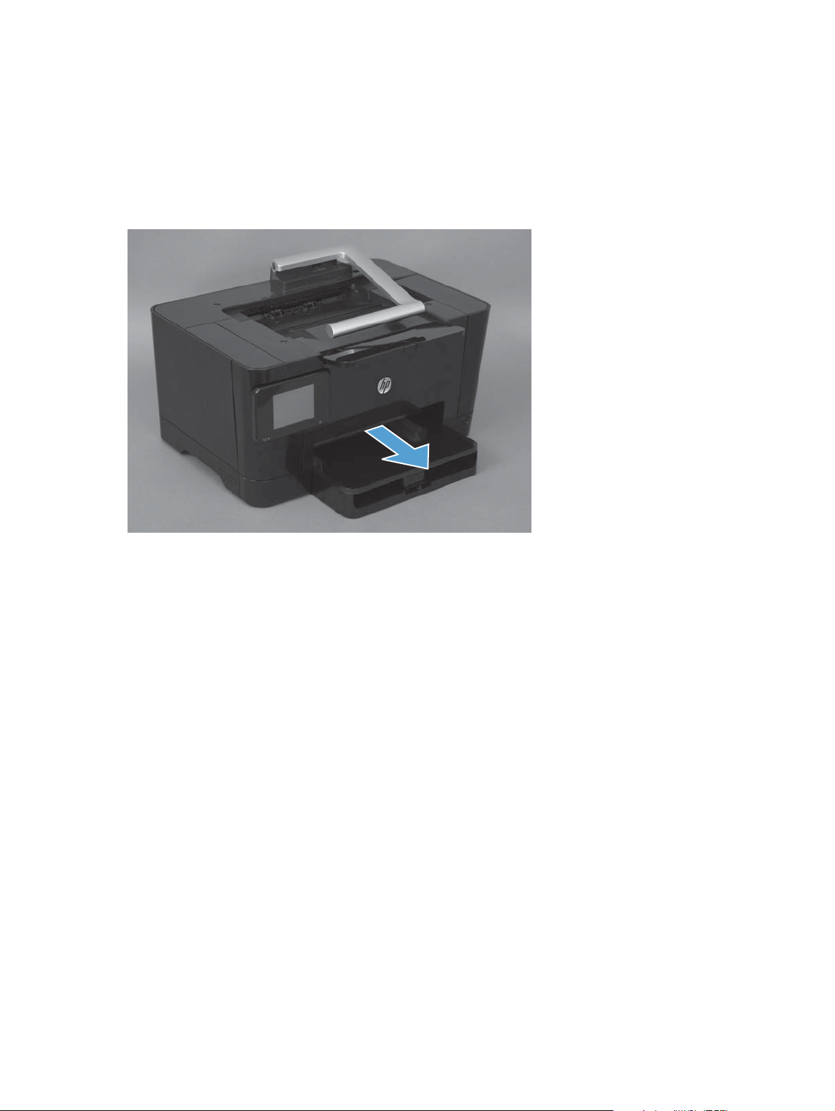
Input tray
Pull the tray away from the product to remove it.
Figure 1-3 Remove the tray
6 Chapter 1 Removal and replacement ENWW
Page 21
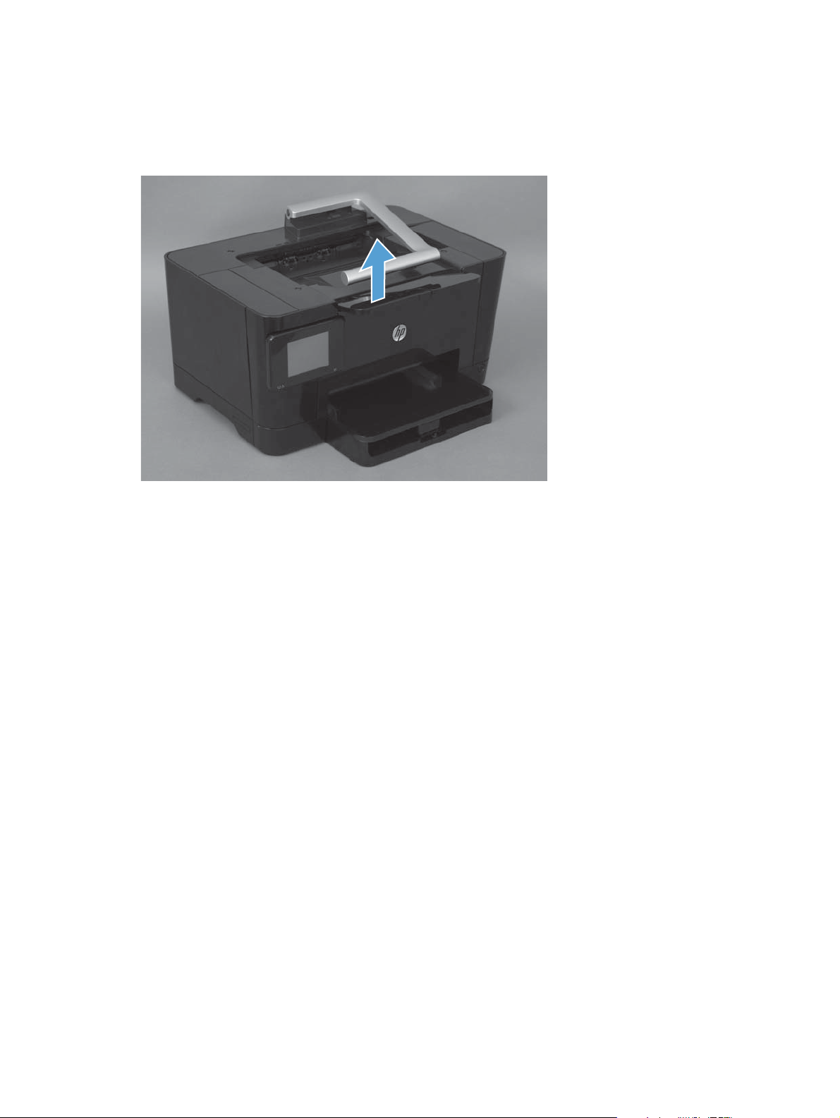
Output bin
Pull the output bin straight up to remove it.
Figure 1-4 Remove the output bin
ENWW
Removal and replacement procedures
7
Page 22

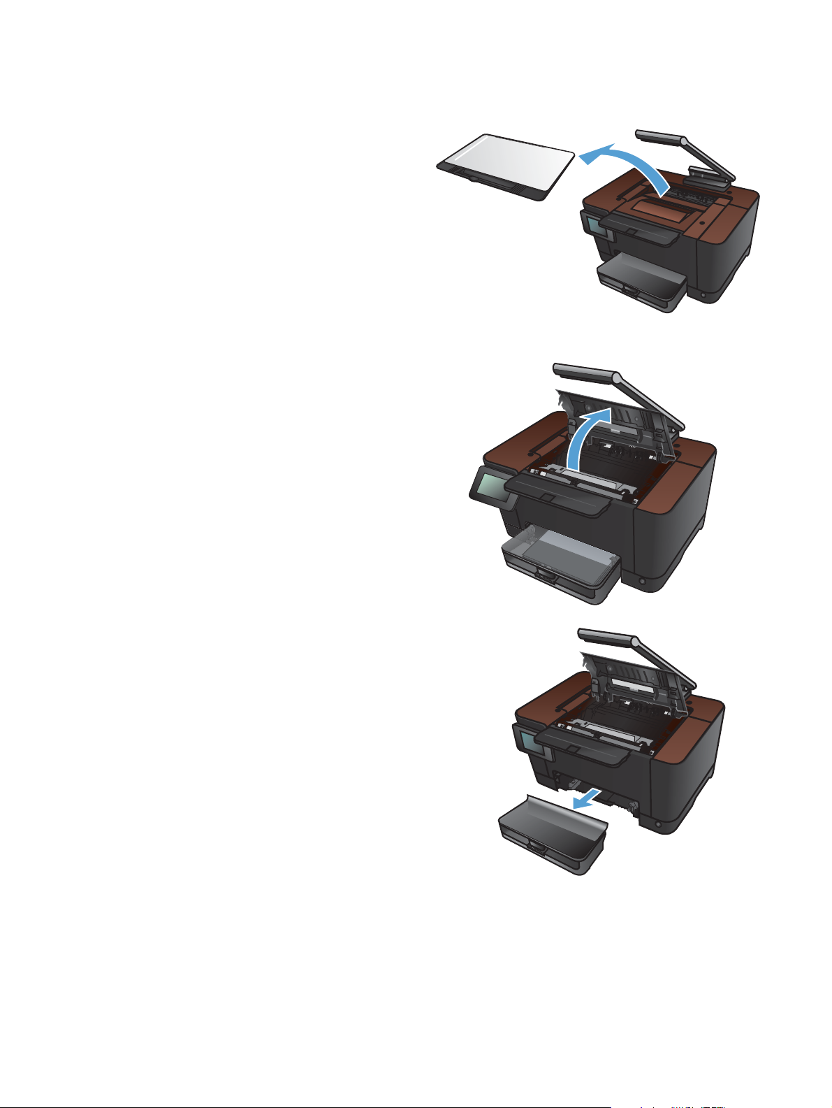
Print cartridges
1. Raise the camera arm to the fully open
position.
2. Remove the capture stage and set it aside.
3. Open the print-cartridge door, and identify
which print cartridge is in the opening.
8 Chapter 1 Removal and replacement ENWW
Page 23

4. If the cartridge that you need to replace is not
in the opening, close the print-cartridge door.
Wait for the product to initialize before
proceeding with the next step.
5. From the Home screen on the product control
panel, touch the Supplies
button.
6. Touch the Cartridge Rotate button to move the
print-cartridge carousel to the next position. A
message informs you of which print cartridge
the carousel is rotating to. Repeat this step until
the print-cartridge carousel is in the correct
position.
NOTE: All doors must be closed when
pressing the Cartridge Rotate button. Also, the
imaging drum must be installed for the
Cartridge Rotate button to work.
ENWW
Removal and replacement procedures
9
Page 24

7. Wait until the Rotating message disappears
and the rotation sounds stop, and then open
the print-cartridge door.
8. Grasp the old print cartridge by the center
handle and remove it.
9. Remove the new print cartridge from the
packaging. Place the used print cartridge in
the bag and box for recycling.
CAUTION: To prevent damage to the print
cartridge, hold the print cartridge at each end.
Do not touch the roller on the print cartridge.
10. Grasp both sides of the new print cartridge
and gently rock it to distribute the toner evenly.
10 Chapter 1 Removal and replacement ENWW
Page 25

11. Grasp the print cartridge by the center handle
and remove the protective plastic shield.
NOTE: Do not touch the print cartridge
roller. Fingerprints on the roller can cause
print-quality problems.
12. Remove the sealing tape from the print
cartridge. Place the tape in the print-cartridge
box to return for recycling.
13. Grasp the print cartridge by the center handle
and insert the print cartridge into the product.
NOTE: Compare the color label on the print
cartridge to the color label in the carousel slot
to make sure the print cartridge color matches
the carousel position. (The black carousel
position has no label.)
CAUTION: If toner gets on your clothing,
wipe it off with a dry cloth and wash the
clothing in cold water. Hot water sets toner
into the fabric.
14. Close the print cartridge door.
NOTE: After closing the print cartridge door,
the control panel shows the Calibrating...
message. Allow a few minutes for the product
to calibrate.
NOTE: If you need to replace another print
cartridge, you must close the print cartridge
door before touching the Cartridge Rotate
button again.
You do not need to wait for the product to
calibrate when replacing the second print
cartridge. Instead, touch the Cartridge Rotate
button to rotate the carousel into position. After
you have replaced the print cartridges, the
product calibrates.
ENWW
Removal and replacement procedures
11
Page 26

15. Reinstall the capture stage.
16. Lower the camera arm.
NOTE: Lower the camera arm to protect the
camera lens cover from damage.
12 Chapter 1 Removal and replacement ENWW
Page 27

Imaging drum
NOTE: The imaging drum installed in this product is covered by the product warranty. Replacement
imaging drums have a one-year limited warranty from the date of installation. The imaging drum
installation date displays on the supplies status page. The HP Premium Protection Warranty applies only
to the print cartridges for the product.
1. Remove the paper from the input tray.
2. Raise the camera arm to the fully open
position.
ENWW
Removal and replacement procedures
13
Page 28
3. Remove the capture stage and set it aside.
4. Open the print-cartridge door.
5. Pull the input tray straight out to remove it.
14 Chapter 1 Removal and replacement ENWW
Page 29

6. Pull out on the top right portion of the front
cover, and rotate it forward to release the right
side. Remove the front cover from the product.
7. Lift the two levers that hold the imaging drum.
8. Remove the old imaging drum.
ENWW
Removal and replacement procedures
15
Page 30

9. Remove the new imaging drum from the
packaging. Place the used imaging drum in
the bag and box for recycling.
10. Remove the protective shielding from the new
imaging drum.
CAUTION: To prevent damage, do not
expose the imaging drum to light. Cover it with
a piece of paper.
CAUTION: Do not touch the green roller.
Fingerprints can cause print-quality problems.
11. Insert the new imaging drum in the product.
12. Lower the two levers that hold the imaging
drum.
16 Chapter 1 Removal and replacement ENWW
Page 31

13. Reinstall the front cover. Insert the left side first,
and then rotate the cover into place.
14. Reinstall the input tray.
15. Close the print-cartridge door.
ENWW
Removal and replacement procedures
17
Page 32

16. Reinstall the capture stage.
17. Lower the camera arm.
NOTE: Lower the camera arm to protect the
camera lens cover from damage.
18 Chapter 1 Removal and replacement ENWW
Page 33

18. Load the paper in the input tray.
19. Adjust the guides until they are snug against
the paper.
ENWW
Removal and replacement procedures
19
Page 34

Secondary transfer roller
CAUTION: Do not touch the black spongy part of the roller. Skin oils might cause print-quality
problems.
1. Open the rear door.
2. Push in on the two clips at the left end of the roller (callout 1), and then rotate the roller up and
pull it to the left to remove it from the product.
Figure 1-5 Remove the secondary transfer roller
1
20 Chapter 1 Removal and replacement ENWW
Page 35

Separation pad assembly
1. Turn the product face up.
NOTE: Dirt and debris can scratch the surface of the product. Make sure that you place the
product face up on a clean work space or on a clean soft cloth.
2. Remove two screws (callout 1) and the separation pad assembly (callout 2).
Figure 1-6 Remove the separation pad assembly (1 of 1)
2
1
ENWW
Removal and replacement procedures
21
Page 36

Covers, pickup roller, and camera arm
Right cover assembly
Remove one screw (callout 1), and then starting at the rear vertical edge, release five tabs
▲
(callout 2) and remove the right cover assembly.
Figure 1-7 Remove the right cover assembly
2
1
22 Chapter 1 Removal and replacement ENWW
Page 37

Left rear cover assembly
Remove one screw (callout 1), and then starting at the rear vertical edge, release seven tabs
▲
(callout 2) and remove the left rear cover assembly.
Figure 1-8 Remove the left rear cover assembly
1
2
ENWW
Removal and replacement procedures
23
Page 38

Pickup roller
Rotate the pickup roller to the service position
To gain access to the roller locking tabs you must rotate the roller to the correct position for removal.
1. Make sure that one sheet of paper is loaded in the input tray.
NOTE: If more than one sheet of paper is loaded in the tray, this procedure will not be
successful.
2. Open the 2ndary Service menu:
a.
When the product is in the Ready state, touch the Setup
b. Touch the area on the control panel where the left arrow would be (callout 1), and then touch
the area on the control panel where the Cancel button would be (callout 2).
NOTE: These buttons are active even when they are not illuminated.
Figure 1-9 Open the 2ndary Service menu
button.
1
2
c.
Touch the Setup
3. Scroll down and touch the Pick roller button. Touch the OK button to rotate the roller to the
removal position.
4. Turn the product off. Unplug the product before removing any components.
NOTE: When the roller is in the removal position, the sheet of paper will have been pulled into
the paper path by about 12 mm (.5 in). This is visual confirmation that the roller has rotated to the
removal position.
24 Chapter 1 Removal and replacement ENWW
button again, and then touch the 2ndary Service button.
Page 39

Before proceeding, remove the following components:
Separation pad assembly. See
●
Right cover assembly. See
●
Left rear cover assembly. See
●
Remove the pickup roller assembly
1. Remove four screws (callout 1) and the lower stay part (callout 2).
Figure 1-10 Remove the pickup roller assembly (1 of 2)
Separation pad assembly on page 21.
Right cover assembly on page 22.
Left rear cover assembly on page 23.
2
1
2. Release two tabs (callout 1) and remove the pickup roller (callout 2).
Figure 1-11 Remove the pickup roller assembly (2 of 2)
1
2
ENWW
Removal and replacement procedures
25
Page 40

Rear door assembly
Before proceeding, remove the following components:
Right cover assembly. See
●
Remove the rear door assembly
1. Remove one screw (callout 1) and the bushing (callout 2).
Figure 1-12 Remove the rear door assembly (1 of 2)
Right cover assembly on page 22.
1
2
2. Pull out the shaft (callout 1) and remove the rear door assembly (callout 2).
Figure 1-13 Remove the rear door assembly (2 of 2)
1
2
26 Chapter 1 Removal and replacement ENWW
Page 41

Rear-lower cover
Before proceeding, remove the following components:
Right cover assembly. See
●
Left rear cover assembly. See
●
Rear door assembly. See
●
Remove the rear-lower cover
Remove two screws (callout 1) and the rear lower cover assembly (callout 2).
Figure 1-14 Remove the rear-lower cover
Right cover assembly on page 22.
Left rear cover assembly on page 23.
Rear door assembly on page 26.
1
2
ENWW
Removal and replacement procedures
27
Page 42

Cosmetic cover
Before proceeding, remove the following components:
Right cover assembly. See
●
Left rear cover assembly. See
●
Remove the cosmetic cover
Remove two screws (callout 1), and then, starting at each end and working toward the center, use
▲
a small flat-blade screwdriver to gently unsnap the cover. Pull the cover straight forward to remove
it.
Figure 1-15 Remove the cosmetic cover
Right cover assembly on page 22.
Left rear cover assembly on page 23.
1
28 Chapter 1 Removal and replacement ENWW
Page 43

Fuser cover
Before proceeding, remove the following components:
Right cover assembly. See
●
Left rear cover assembly. See
●
Cosmetic cover. See
●
Remove the fuser cover
Release four tabs, and starting at the top, pull off the fuser cover.
▲
Figure 1-16 Remove the fuser cover
Right cover assembly on page 22.
Left rear cover assembly on page 23.
Cosmetic cover on page 28.
ENWW
Removal and replacement procedures
29
Page 44

Camera arm assembly
NOTE: The formatter board contains camera-arm calibration data that is specific to each camera
arm. Camera arms cannot be swapped between units. Replacement camera arms require re-calibration
to create new calibration data.
Before proceeding, remove the following components:
Right cover assembly. See
●
Left rear cover assembly. See
●
Cosmetic cover. See
●
Fuser cover. See
●
Remove the camera arm assembly
1. On the left side of the product, disconnect one connector and one FFC (callout 1) from the
formatter. Thread them up through the opening in the top cover.
Figure 1-17 Remove the camera arm assembly (1 of 6)
Cosmetic cover on page 28.
Fuser cover on page 29.
1
Right cover assembly on page 22.
Left rear cover assembly on page 23.
30 Chapter 1 Removal and replacement ENWW
Page 45

2. Remove the rubber cap from the end of the base of the camera arm.
Figure 1-18 Remove the camera arm assembly (2 of 6)
3. Remove the hinge screw.
Figure 1-19 Remove the camera arm assembly (3 of 6)
ENWW
Removal and replacement procedures
31
Page 46

4. Release the adhesive on the FFC (callout 1), route the wire bundle through the guide (callout 2).
Rotate the camera arm forward and pull it up to release the spring (callout 3).
NOTE: Two ferrite cores are attached to the FFC. They are not shown in this photograph.
Figure 1-20 Remove the camera arm assembly (4 of 6)
3
2
1
5. Remove one screw (callout 1) to release the grounding cable, and then remove the camera arm
assembly.
Figure 1-21 Remove the camera arm assembly (5 of 6)
1
32 Chapter 1 Removal and replacement ENWW
Page 47

6. If you need to install a different camera-arm alignment plate, remove the rectangular plate (callout
1) by sliding it to the right, and then remove one Torx6 screw to remove the alignment plate
(callout 2).
Figure 1-22 Remove the camera arm assembly (6 of 6)
2
1
ENWW
Removal and replacement procedures
33
Page 48

Top cover assembly
Before proceeding, remove the following components:
Right cover assembly. See
●
Left rear cover assembly. See
●
Cosmetic cover. See
●
Fuser cover. See
●
Camera arm assembly. See
●
Remove the top cover assembly
1. Remove one screw (callout 1), and then remove the wireless PCA at the top right corner of the
formatter.
Figure 1-23 Remove the top cover assembly (1 of 4)
Fuser cover on page 29.
Right cover assembly on page 22.
Left rear cover assembly on page 23.
Cosmetic cover on page 28.
Camera arm assembly on page 30.
1
34 Chapter 1 Removal and replacement ENWW
Page 49

2. Remove two screws (callout 1).
Figure 1-24 Remove the top cover assembly (2 of 4)
1
3. Push the door hinge to the left to release it.
Figure 1-25 Remove the top cover assembly (3 of 4)
ENWW
Removal and replacement procedures
35
Page 50

4. Flex the top cover to release it from the horizontal shaft in two locations (callout 1), and remove
the top cover assembly.
CAUTION: When removing and reinstalling this cover, be careful not to bend the two small
springs that are directly beneath the print-cartridge door hinges.
Figure 1-26 Remove the top cover assembly (4 of 4)
1
36 Chapter 1 Removal and replacement ENWW
Page 51

Door hinge
Before proceeding, remove the following components:
Right cover assembly. See
●
Left rear cover assembly. See
●
Cosmetic cover. See
●
Fuser cover. See
●
Camera arm assembly. See
●
Top cover assembly. See
●
Remove the door hinge
Rotate the door hinge to the right to release the pins, and then release the spring (callout 1).
▲
Figure 1-27 Remove the door hinge
Right cover assembly on page 22.
Left rear cover assembly on page 23.
Cosmetic cover on page 28.
Fuser cover on page 29.
Camera arm assembly on page 30.
Top cover assembly on page 34
1
ENWW
Removal and replacement procedures
37
Page 52

Left front cover and control panel assembly
Before proceeding, remove the following components:
Right cover assembly. See
●
Left rear cover assembly. See
●
Cosmetic cover. See
●
Fuser cover. See
●
Camera arm assembly. See
●
Top cover assembly. See
●
Remove the left front cover and control panel assembly
1. On the formatter, disconnect two FFCs (callout 1), and disconnect the control-panel grounding
cable (callout 2).
Figure 1-28 Remove the left front cover and control panel assembly (1 of 5)
Fuser cover on page 29.
Right cover assembly on page 22.
Left rear cover assembly on page 23.
Cosmetic cover on page 28.
Camera arm assembly on page 30.
Top cover assembly on page 34.
1
2
38 Chapter 1 Removal and replacement ENWW
Page 53

2. Inside the left front cover, near the bottom, push up on the tab (callout 1) to release it.
Figure 1-29 Remove the left front cover and control panel assembly (2 of 5)
1
3. Rotate the left front cover to the right and slightly down to release the pin. Remove the left front
cover and control panel assembly.
Figure 1-30 Remove the left front cover and control panel assembly (3 of 5)
ENWW
Removal and replacement procedures
39
Page 54

4. To separate the control panel from the left front cover, extend the control panel to its fully open
position. Pull down on the control-panel release bracket (callout 1) hold it open while you push the
control-panel kickstand through the slot (callout 2).
Figure 1-31 Remove the left front cover and control panel assembly (4 of 5)
1
5. Push the control-panel kickstand straight up to remove it.
Figure 1-32
2
40 Chapter 1 Removal and replacement ENWW
Page 55

Top-upper-left front cover
Before proceeding, remove the following components:
Right cover assembly. See
●
Left rear cover assembly. See
●
Cosmetic cover. See
●
Fuser cover. See
●
Camera arm assembly. See
●
Top cover assembly. See
●
Left front cover and control panel assembly (through step 3). See
●
assembly on page 38.
Remove the top-upper-left front cover
1. Underneath the top-upper-left front cover, remove one screw (callout 1).
Figure 1-33 Remove the top-upper-left front cover (1 of 2)
Fuser cover on page 29.
Right cover assembly on page 22.
Cosmetic cover on page 28.
Top cover assembly on page 34.
Left rear cover assembly on page 23.
Camera arm assembly on page 30.
Left front cover and control panel
1
ENWW
Removal and replacement procedures
41
Page 56

2. Remove one screw (callout 1), and release one tab (callout 2). Remove the top-upper-left front
cover.
Figure 1-34 Remove the top-upper-left front cover (2 of 2)
21
42 Chapter 1 Removal and replacement ENWW
Page 57

Top-upper-right front cover
Before proceeding, remove the following components:
Right cover assembly. See
●
Left rear cover assembly. See
●
Cosmetic cover. See
●
Fuser cover. See
●
Camera arm assembly. See
●
Top cover assembly. See
●
Remove the top-upper-right front cover
Remove two screws (callout 1), and remove the top-upper-right front cover.
▲
Figure 1-35 Remove the top-upper-right front cover
Fuser cover on page 29.
Right cover assembly on page 22.
Left rear cover assembly on page 23.
Cosmetic cover on page 28.
Camera arm assembly on page 30.
Top cover assembly on page 34.
1
ENWW
Removal and replacement procedures
43
Page 58

Inner cover
Before proceeding, remove the following components:
Right cover assembly. See
●
Left rear cover assembly. See
●
Cosmetic cover. See
●
Fuser cover. See
●
Camera arm assembly. See
●
Top cover assembly. See
●
Left front cover and control panel assembly (through step 3). See
●
assembly on page 38.
Top-upper-left-front cover. See
●
Remove the inner cover
Remove two screws (callout 1), and remove the inner cover.
▲
Figure 1-36 Remove the inner cover
Right cover assembly on page 22.
Left rear cover assembly on page 23.
Cosmetic cover on page 28.
Fuser cover on page 29.
Camera arm assembly on page 30.
Top cover assembly on page 34.
Left front cover and control panel
Remove the top-upper-left front cover on page 41.
1
44 Chapter 1 Removal and replacement ENWW
Page 59

Main assemblies
Formatter and wireless PCA
CAUTION: ESD sensitive.
Before proceeding, remove the following components:
Left rear cover assembly. See
●
Remove the formatter and wireless PCA
1. Remove one screw (callout 1), and then remove the wireless PCA at the top right corner of the
formatter.
Figure 1-37 Remove the formatter and wireless PCA (1 of 3)
Left rear cover assembly on page 23.
1
ENWW
Removal and replacement procedures
45
Page 60

2. Disconnect three connectors and four FFCs (callout 1).
Figure 1-38 Remove the formatter and wireless PCA (2 of 3)
1
3. Remove four screws (callout 1), and then remove the formatter PCA.
Figure 1-39 Remove the formatter and wireless PCA (3 of 3)
1
46 Chapter 1 Removal and replacement ENWW
Page 61

Fuser power supply
CAUTION: ESD sensitive.
Before proceeding, remove the following components:
Left rear cover. See
●
Remove the fuser power supply
1. Disconnect four connectors (callout 1)
Figure 1-40 Remove the fuser power supply (1 of 2)
Left rear cover assembly on page 23.
1
ENWW
2. Remove three screws (callout 1), and then remove the fuser power supply.
Figure 1-41 Remove the fuser power supply (2 of 2)
1
Removal and replacement procedures
47
Page 62

ITB assembly
CAUTION: ESD sensitive.
NOTE: If you have not removed the image drum before servicing the product, remove it now. See
Imaging drum on page 13.
Before proceeding, remove the following components:
Right cover assembly. See
●
Left rear cover assembly. See
●
Cosmetic cover. See
●
Fuser cover. See
●
Rear door. See
●
Rear-lower cover. See
●
Camera arm assembly. See
●
Top cover assembly. See
●
Left front cover and control panel assembly (through step 3). See
●
assembly on page 38.
Top-upper-left-front cover. See
●
Inner cover. See
●
Formatter and wireless PCA. See
●
Fuser cover on page 29.
Rear door assembly on page 26.
Inner cover on page 44.
Right cover assembly on page 22.
Left rear cover assembly on page 23.
Cosmetic cover on page 28.
Rear-lower cover on page 27.
Camera arm assembly on page 30.
Top cover assembly on page 34.
Remove the top-upper-left front cover on page 41.
Formatter and wireless PCA on page 45.
Left front cover and control panel
48 Chapter 1 Removal and replacement ENWW
Page 63

Remove the ITB assembly
1. Disconnect four connectors (callout 1).
Figure 1-42 Remove the ITB assembly (1 of 17)
2. Remove five screws (callout 1), and then separate the sheet-metal plate (callout 2) and fuser power
supply (callout 3) from the product.
1
CAUTION: The sheet-metal plate and fuser power supply assembly is still attached to the
product by a FFC connected to the engine controller assembly. Do not attempt to completely
remove the assembly.
Figure 1-43 Remove the ITB assembly (2 of 17)
1
2
3
ENWW
Removal and replacement procedures
49
Page 64

3. Disconnect one FFC (Callout 1), and then remove the sheet-metal plate and fuser power supply
assembly.
Figure 1-44 Remove the ITB assembly (3 of 17)
1
4. Release one tab (callout 1), and then remove the cable cover (callout 2).
Figure 1-45 Remove the ITB assembly (4 of 17)
2
1
50 Chapter 1 Removal and replacement ENWW
Page 65

5. Disconnect one connector (callout 1), release the wire harnesses (callout 2) from the guide (callout
3).
Figure 1-46 Remove the ITB assembly (5 of 17)
1
2
3
6. Release one tab (callout 1), and then remove the rear-door left-side arm (callout 2).
Figure 1-47 Remove the ITB assembly (6 of 17)
2
1
ENWW
Removal and replacement procedures
51
Page 66

7. Release the hook end (callout 1) of the ITB fixing spring (callout 2).
Figure 1-48 Remove the ITB assembly (7 of 17)
1
2
8. Rotate the spring (callout 1) so that it faces out of the product.
Figure 1-49 Remove the ITB assembly (8 of 17)
1
52 Chapter 1 Removal and replacement ENWW
Page 67

9. Rotate the ITB fixing part (callout 1) so that it faces out of the product.
Figure 1-50 Remove the ITB assembly (9 of 17)
1
Figure 1-51 Remove the ITB assembly (10 of 17)
1
ENWW
Removal and replacement procedures
53
Page 68

10. Release two tabs (callout 1), and then remove the spring cover (callout 2).
Figure 1-52 Remove the ITB assembly (11 of 17)
1
2
11. Release one tab (callout 1), and the remove the rear-door right-side arm (callout 2).
Figure 1-53 Remove the ITB assembly (12 of 17)
1
2
54 Chapter 1 Removal and replacement ENWW
Page 69
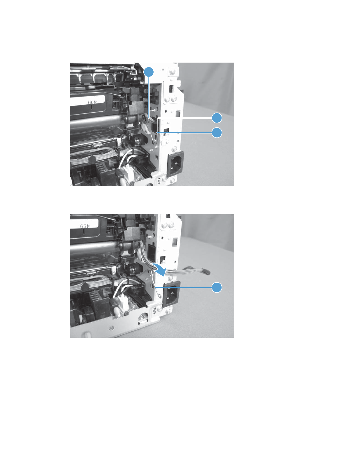
12. Release the hook end (callout 1) of the ITB fixing spring (callout 2), and then pull the wire harness
(callout 3) through the hole in the chassis.
Figure 1-54 Remove the ITB assembly (13 of 17)
3
1
2
13. Rotate the spring (callout 1) so that it faces out of the product.
Figure 1-55 Remove the ITB assembly (14 of 17)
1
ENWW
Removal and replacement procedures
55
Page 70

14. Rotate the ITB fixing part (callout 1) so that it faces out of the product.
Figure 1-56 Remove the ITB assembly (15 of 17)
1
Figure 1-57 Remove the ITB assembly (16 of 17)
1
56 Chapter 1 Removal and replacement ENWW
Page 71

15. Pull the ITB assembly (callout 1) straight out of the product.
CAUTION: Avoid touching the black plastic transfer belt. Skin oils on the belt might cause print-
quality problems.
Figure 1-58 Remove the ITB assembly (17 of 17)
1
ENWW
Removal and replacement procedures
57
Page 72

Fuser delivery assembly
NOTE: For this product, the fuser and the paper delivery components are one assembly.
Position the fuser pressure roller for removal
You must rotate the pressure roller to the correct position before removing the fuser delivery assembly.
1. When the product is in the Ready state, press and hold the Auto-On/Auto-Off (power) button for
about seven seconds or until you hear subtle movement within the product and the Ready light
turns off.
2. Release the Auto-On/Auto-Off (power) button. The product power will be off and the fuser
pressure roller is in the removal position. Unplug the product before removing any components.
NOTE: If you have not removed the imaging drum before servicing the product, remove it now. See
Imaging drum on page 13.
Before proceeding, remove the following components:
Right cover assembly. See
●
Left rear cover assembly. See
●
Cosmetic cover. See
●
Fuser cover. See
●
Rear door. See
●
Rear-lower cover. See
●
Camera arm assembly. See
●
Top cover assembly. See
●
Left front cover and control panel assembly (through step 3). See
●
assembly on page 38.
Top-upper-left-front cover. See
●
Inner cover. See
●
Formatter and wireless PCA. See
●
Fuser cover on page 29.
Rear door assembly on page 26.
Inner cover on page 44.
Right cover assembly on page 22.
Left rear cover assembly on page 23.
Cosmetic cover on page 28.
Rear-lower cover on page 27.
Camera arm assembly on page 30.
Top cover assembly on page 34.
Remove the top-upper-left front cover on page 41.
Formatter and wireless PCA on page 45.
Left front cover and control panel
58 Chapter 1 Removal and replacement ENWW
Page 73

Remove the fuser delivery assembly
CAUTION: ESD sensitive.
1. Disconnect four connectors.
Figure 1-59 Remove the fuser delivery assembly (1 of 6)
1
2. Remove five screws (callout 1), and then separate the sheet-metal plate (callout 2) and fuser power
supply (callout 3) from the product.
CAUTION: The sheet-metal plate and fuser power supply assembly is still attached to the
product by a FFC connected to the engine controller assembly. Do not attempt to completely
remove the assembly.
Figure 1-60 Remove the fuser delivery assembly (2 of 6)
1
2
3
ENWW
Removal and replacement procedures
59
Page 74

3. Disconnect one FFC (Callout 1), and then remove the sheet-metal plate and fuser power supply
assembly.
Figure 1-61 Remove the fuser delivery assembly (3 of 6)
1
4. Release one tab (callout 1), and then remove the cable cover (callout 2).
Figure 1-62 Remove the fuser delivery assembly (4 of 6)
2
1
60 Chapter 1 Removal and replacement ENWW
Page 75

5. Disconnect four connectors (callout 1), Release the wire harnesses (callout 2) from the guide
(callout 3).
Figure 1-63 Remove the fuser delivery assembly (5 of 6)
2
3
1
6. Remove five screws (callout 1), and then remove the fuser delivery assembly (callout 2).
Figure 1-64 Remove the fuser delivery assembly (6 of 6)
1
2
ENWW
Removal and replacement procedures
61
Page 76

Reinstall the fuser delivery assembly
When reassembling the fuser delivery assembly, be sure the drive cam (callout 1) for fuser
▲
pressure release is positioned as shown below.
Figure 1-65 Reinstall the fuser delivery assembly (1 of 2)
1
Figure 1-66 Reinstall the fuser delivery assembly (2 of 2)
1
62 Chapter 1 Removal and replacement ENWW
Page 77

Engine controller assembly
CAUTION: ESD sensitive.
Before proceeding, remove the following components:
Right cover assembly. See
●
Left rear cover assembly. See
●
Cosmetic cover. See
●
Fuser cover. See
●
Rear door. See
●
Rear-lower cover. See
●
Camera arm assembly. See
●
Top cover assembly. See
●
Left front cover and control panel assembly (through step 3). See
●
assembly on page 38.
Top-upper-left-front cover. See
●
Inner cover. See
●
Formatter and wireless PCA. See
●
Remove the engine controller assembly
Fuser cover on page 29.
Rear door assembly on page 26.
Inner cover on page 44.
Right cover assembly on page 22.
Left rear cover assembly on page 23.
Cosmetic cover on page 28.
Rear-lower cover on page 27.
Camera arm assembly on page 30.
Top cover assembly on page 34.
Left front cover and control panel
Remove the top-upper-left front cover on page 41.
Formatter and wireless PCA on page 45.
ENWW
1. Disconnect four connectors.
Figure 1-67 Remove the engine controller assembly (1 of 7)
1
Removal and replacement procedures
63
Page 78

2. Remove five screws (callout 1), and then separate the sheet-metal plate (callout 2) and fuser power
supply (callout 3) from the product.
CAUTION: The sheet-metal plate and fuser power supply assembly is still attached to the
product by a FFC connected to the engine controller assembly. Do not attempt to completely
remove the assembly.
Figure 1-68 Remove the engine controller assembly (2 of 7)
1
2
3
3. Disconnect one FFC (Callout 1), and then remove the sheet-metal plate and fuser power supply
assembly.
Figure 1-69 Remove the engine controller assembly (3 of 7)
1
64 Chapter 1 Removal and replacement ENWW
Page 79

4. Release one tab (callout 1) and remove the cable cover (callout 2).
Figure 1-70 Remove the engine controller assembly (4 of 7)
2
1
5. Release one tab (callout 1), and then remove the cover (callout 2).
Figure 1-71 Remove the engine controller assembly (5 of 7)
1
2
ENWW
Removal and replacement procedures
65
Page 80

6. Disconnect eleven connectors (callout 1).
Figure 1-72 Remove the engine controller assembly (6 of 7)
1
7. Remove six screws (callout 1), release two tabs (callout 2), and then remove the engine controller
assembly.
Figure 1-73 Remove the engine controller assembly (7 of 7)
1
2
66 Chapter 1 Removal and replacement ENWW
Page 81

Installing a replacement engine controller assembly
Release one tab (callout 1), remove the guide (callout 2) from the discarded engine controller assembly
(callout 3), and then install the guide on the replacement assembly.
Figure 1-74 Installing a replacement engine controller assembly
3
1
2
ENWW
Removal and replacement procedures
67
Page 82

Low-voltage power supply assembly
CAUTION: ESD sensitive.
Before proceeding, remove the following components:
Right cover assembly. See
●
Left rear cover assembly. See
●
Cosmetic cover. See
●
Fuser cover. See
●
Rear door. See
●
Rear-lower cover. See
●
Camera arm assembly. See
●
Top cover assembly. See
●
Left front cover and control panel assembly (through step 3). See
●
assembly on page 38.
Top-upper-left-front cover. See
●
Inner cover. See
●
Formatter and wireless PCA. See
●
Remove the low-voltage power supply assembly
Fuser cover on page 29.
Rear door assembly on page 26.
Inner cover on page 44.
Right cover assembly on page 22.
Left rear cover assembly on page 23.
Cosmetic cover on page 28.
Rear-lower cover on page 27.
Camera arm assembly on page 30.
Top cover assembly on page 34.
Remove the top-upper-left front cover on page 41.
Formatter and wireless PCA on page 45.
Left front cover and control panel
1. Disconnect four connectors.
Figure 1-75 Remove the low-voltage power supply assembly (1 of 9)
1
68 Chapter 1 Removal and replacement ENWW
Page 83

2. Remove five screws (callout 1), and then separate the sheet-metal plate (callout 2) and fuser power
supply (callout 3) from the product.
CAUTION: The sheet-metal plate and fuser power supply assembly is still attached to the
product by a FFC connected to the engine controller assembly. Do not attempt to completely
remove the assembly.
Figure 1-76 Remove the low-voltage power supply assembly (2 of 9)
1
2
3
3. Disconnect one FFC (Callout 1), and then remove the sheet-metal plate and fuser power supply
assembly.
Figure 1-77 Remove the low-voltage power supply assembly (3 of 9)
1
ENWW
Removal and replacement procedures
69
Page 84

4. Release one cable from the cable guide (callout 1), and then remove two screws (callout 2).
Figure 1-78 Remove the low-voltage power supply assembly (4 of 9)
2
5. Remove the power receptacle (callout 1) and guide (callout 2) as an assembly.
Reinstallation tip Make sure that these parts are correctly assembled, before reinstalling the
receptacle and guide. See
Figure 1-79 Remove the low-voltage power supply assembly (5 of 9)
Reinstall the low-voltage power supply on page 73.
1
2
1
70 Chapter 1 Removal and replacement ENWW
Page 85

6. Place the product rear-side up, and then remove four screws (callout 1).
Figure 1-80 Remove the low-voltage power supply assembly (6 of 9)
1
7. Remove three screws (callout 1), disconnect one connector (callout 2) and separate the low-
voltage power supply assembly (callout 3) from the product.
CAUTION: Do not attempt to completely remove the low-voltage power supply. The power
supply is still connected to the product by three internal connectors.
Figure 1-81 Remove the low voltage power supply assembly (7 of 9)
2
3
1
ENWW
Removal and replacement procedures
71
Page 86

8. Release the wire harness (callout 1) from the guide (callout 2), and then pull the wire harness
through the hole in the chassis.
Figure 1-82 Remove the low-voltage power supply assembly (8 of 9)
2
1
9. Disconnect three connectors (callout 1) and remove the low-voltage power supply assembly
(callout 2).
Figure 1-83 Remove the low-voltage power supply assembly (9 of 9)
1
2
72 Chapter 1 Removal and replacement ENWW
Page 87

Reinstall the low-voltage power supply
Make sure that the power receptacle (callout 1), guide (callout 2), and the ferrite (callout 3) are
correctly assembled before installing them.
Figure 1-84 Reinstall the low-voltage power supply
1 2 3
Installing a replacement low-voltage power supply
Release two tabs (callout 1), remove the cover (callout 2) from the discarded low-voltage power supply,
and then install the guide on the replacement assembly.
Figure 1-85 Installing a replacement low-voltage power supply
2
1
ENWW
Removal and replacement procedures
73
Page 88

2 Solve problems
Solve problems checklist
●
Print product reports
●
Troubleshooting processes
●
Tools for troubleshooting
●
Clear jams
●
Paper feeds incorrectly or becomes jammed
●
Improve print quality
●
Improve copy quality
●
The product prints slowly
●
Solve USB connection problems
●
Solve wired network problems
●
Solve wireless network problems
●
Service mode functions
●
Product updates
●
ENWW 75
Page 89

Solve problems checklist
Follow these steps when trying to solve a problem with the product.
Step 1: Make sure that the product is set up correctly
●
Step 2: Check the cabling or wireless connection
●
Step 3: Check the control panel for error messages
●
Step 4: Check the paper
●
Step 5: Check the software
●
Step 6: Test print functionality
●
Step 7: Test copy functionality
●
Step 8: Check the supplies
●
Step 9: Try sending a print job from a computer
●
Step 1: Make sure that the product is set up correctly
1. Press the power button to turn on the product or to deactivate the Auto-Off mode.
2. Check the power-cable connections.
3. Make sure that the line voltage is correct for the product power configuration. (See the label that is
inside the product front cover for voltage requirements.) If you are using a power strip and its
voltage is not within specifications, plug the product directly into the wall. If it is already plugged
into the wall, try a different outlet.
4. If none of these measures restores power, contact HP Customer Care.
Step 2: Check the cabling or wireless connection
1. Check the cable connection between the product and the computer. Make sure that the connection
is secure.
2. Make sure that the cable itself is not faulty by using a different cable, if possible.
3. If the product is connected to a network, check the following items:
Check the light next to the network connection on the product. If the network is active, the
●
light is green.
Make sure that you are using a network cable and not a phone cord to connect to the
●
network.
76 Chapter 2 Solve problems ENWW
Page 90

Make sure the network router, hub, or switch is turned on and that it is working correctly.
●
If your computer or the product is connected to a wireless network, low signal quality or
●
interference might be delaying print jobs.
4. If you are using a personal firewall system on the computer, it might be blocking communication
with the product. Try temporarily disabling the firewall to see if it is the source of the problem.
Step 3: Check the control panel for error messages
The control panel should indicate ready status. If an error message appears, resolve the error.
Step 4: Check the paper
1. Make sure that the paper that you are using meets specifications.
2. Make sure that the paper is loaded correctly in the input tray.
Step 5: Check the software
1. Make sure that the product software is installed correctly.
2. Verify that you have installed the printer driver for this product. Check the program to make sure
that you are using the printer driver for this product.
Step 6: Test print functionality
1. Print a configuration page.
2. If the page does not print, verify that the input tray contains paper.
3. If the page jams in the product, clear the jam.
Step 7: Test copy functionality
1. Place the configuration page onto the capture stage and make a copy.
2. If the print quality on the copied pages is not acceptable, clean the cover over the camera lens
with a soft cloth or sponge that has been moistened with nonabrasive glass cleaner.
CAUTION: Do not use abrasives, acetone, benzene, ammonia, ethyl alcohol, or carbon
tetrachloride on any part of the product; these can damage the product. Do not place liquids
directly on the capture stage. They might seep and damage the product.
Step 8: Check the supplies
Print a supplies status page and check remaining life of the print cartridges and imaging drum.
ENWW
Solve problems checklist
77
Page 91

Step 9: Try sending a print job from a computer
1. Try printing the job from another computer that has the product software installed.
2. Check the USB or network cable connection. Direct the product to the correct port, or reinstall the
software, selecting the connection type that you are using.
3. If the print quality is unacceptable, verify that the print settings are correct for the media that you
are using.
78 Chapter 2 Solve problems ENWW
Page 92

Print product reports
From the Reports menu, you can print several informative pages about the product.
1.
From the Home screen, touch the Setup
button.
2. Touch the Reports button.
3. Touch the name of the report that you want to print.
Menu item Description
Demo Page Prints a page that demonstrates print quality
Menu Structure Prints a map of the control panel-menu layout. The active settings for each menu are
listed.
Config Report Prints a list of all the product settings. Includes network information when the
product is connected to a network.
Supplies Status Prints the status for each print cartridge, including the following information:
Estimated percentage of cartridge life remaining
●
Approximate pages remaining
●
Part numbers for HP print cartridges
●
Number of pages printed
●
Information about ordering new HP print cartridges and recycling used HP
●
print cartridges
Network Summary Prints a list of all product network settings
Usage Page Prints a page that lists PCL pages, PCL 6 pages, PS pages, pages that were jammed
or mispicked in the product, monochrome (black and white) or color pages; and
reports the page count
PCL Font List Prints a list of all the PCL fonts that are installed
PS Font List Prints a list of all the PostScript (PS) fonts that are installed
PCL6 Font List Prints a list of all the PCL6 fonts that are installed
Color Usage Log Prints a report that shows the user name, application name, and color usage
information on a job-by-job basis
Service Page Prints the service report
Diagnostics Page Prints the calibration and color diagnostics pages
Print Quality Page Prints a page that helps solve problems with print quality
ENWW
Print product reports
79
Page 93

Troubleshooting processes
Determine the problem source
The following table includes basic questions to ask the customer to quickly help define the problem or
problems.
General topic Questions
Environment
Paper
Input tray
Is the product installed on a solid, level surface (± 1°)?
●
Is the power-supply voltage within ± 10 volts of the specified power source?
●
Is the power-supply plug inserted in the product and the outlet?
●
Is the operating environment within the specified parameters?
●
Is the product exposed to ammonia gas, such as that produced by diazo
●
copiers or office cleaning materials?
NOTE: Diazo copiers produce ammonia gas as part of the coping
processes. Ammonia gas (from cleaning supplies or a diazo copier) can have
an adverse affect on some product components (for example, the imaging
drum).
Is the product exposed to direct sunlight?
●
Does the customer use only supported paper?
●
Is the paper in good condition (no curls, folds, or distortion)?
●
Is the paper stored correctly and within environmental limits?
●
Is the amount of paper in the tray within specifications?
●
Is the paper correctly placed in the tray?
●
Are the paper guides aligned with the stack?
●
Supplies
Transfer roller and fuser
Covers
Are the print cartridges and the imaging-drum installed correctly and firmly
●
seated?
Has the sealing tape been removed from each print cartridge?
●
Are the print cartridges and imaging drum within their estimated life? (Check
●
the supplies status page.)
Are the transfer roller and fuser installed correctly?
●
Are the top, front and rear doors firmly closed?
●
80 Chapter 2 Solve problems ENWW
Page 94

General topic Questions
Condensation
Miscellaneous
Power subsystem
Power-on checks
Turn on the power. If the control-panel LEDs do not illuminate, perform the power-on checks to find the
cause of the problem.
1. Verify that the product is plugged into an active electrical outlet that delivers the correct voltage.
2. Make sure that the product makes the expected start up sounds.
Does condensation occur following a temperature change (particularly in
●
winter following cold storage)? If so, wipe affected parts dry or leave the
product on for 90 to 120 minutes.
Was a cartridge opened soon after being moved from a cold to a warm
●
room? If so, allow the cartridge to sit at room temperature for 1 to 2 hours.
Check for and remove any non-HP components (for example, a print cartridge
●
or imaging drum) from the product.
Remove the product from the network and make sure that the failure is with the
●
product before beginning troubleshooting.
NOTE: The overcurrent/overvoltage protection circuit in the low-voltage power supply unit might
be functioning. Turn the product off, unplug the power cord, and turn the product on. If the
product does not function, the fuse melts, or the power supply is malfunctioning, replace the
engine controller unit. See
Engine controller assembly on page 63.
ENWW
Troubleshooting processes
81
Page 95

Tools for troubleshooting
Component diagnostics
Engine diagnostics
Printing an engine test page helps determine if the product engine is functioning. Use the following
procedure to print a test page to make sure that the product engine is functioning.
Engine test
NOTE: The product does not have an engine test button.
1. Make sure that at least one sheet of paper is loaded in the input tray.
2. With the product off, open the print-cartridge door and the rear door.
3. Turn the power on, and close both doors within ten seconds.
4. An engine test page (a page containing multiple horizontal lines) prints.
82 Chapter 2 Solve problems ENWW
Page 96

Diagrams
Locations of formatter connectors
Figure 2-1 Locations of formatter connectors
1 2 3
7
4
5
6
Item Connector Description
1 J7 Camera assembly
2 J11 Camera assembly
3 J8 Control panel
4 J3 Engine controller assembly
5 J14 Low-voltage power supply
6 J18 Engine controller assembly
7 J2 Control-panel display
ENWW
Tools for troubleshooting
83
Page 97

Locations of major components
Cross section view
Figure 2-2 Cross section view
Item Description Item Description
1 Pressure roller 10 T1 pad
2 Delivery roller 11 ITB
3 Fuser film assembly 12 Pickup roller
4 Density ITB_TOP sensor 13 Separation pad
5 Print cartridge 14 Feed roller
6 Imaging drum 15 T2 roller
7 Imaging-drum 16 ITB drive roller
8 Laser scanner assembly 17 ITB cleaning brush
9 Input tray 18 ITB cleaning roller
84 Chapter 2 Solve problems ENWW
Page 98

External covers and doors (front view)
Figure 2-3 External covers and doors (front view)
3
2
1
7
6
5
1 Top-upper-left front cover
2 Top cover assembly
3 Cosmetic cover
4 Top-upper-right front cover
4
5 Left front cover
6IOT cover
7 Left cover assembly
ENWW
Tools for troubleshooting
85
Page 99

External covers and doors (rear view)
Figure 2-4 External covers and doors (rear view)
1
2
4
1 Fuser cover
2Rear door
3 Lower rear door
4Right cover assembly
3
86 Chapter 2 Solve problems ENWW
Page 100

General timing chart
Figure 2-5 General timing diagram
PRINTINTR LSTR
ENWW
Print command
STBY STBY
Operation
Fuser motor
TOP sensor3
4 Delivery sensor
2 Pickup motor
Timing chart two consecutive prints on LTR paper (Full-color 1/1 speed mode)
1 Cassette pickup solenoid
5
Main motor7
6 Scanner motor
9 ITB_TOP signal
8 TOP signal
12 Developing bias
11 Carousel motor
10 Primary charging bias
T1 bias
T2 roller ITB cleaner solenoid
13
15 T2 bias
14
Tools for troubleshooting
87
 Loading...