

Page 1

Maintenance and Service
Guide
HP Docking Station
HP Advanced Docking Station
Document Part Number: 381882-003
May 2007
This guide is a troubleshooting reference used for maintaining
and servicing the HP Docking Station and the HP Advanced
Docking Station. It provides comprehensive information on
identifying docking station features, components, and spare parts;
troubleshooting problems; and performing disassembly
procedures.
Page 2

© Copyright 2005–2007 Hewlett-Packard Development Company, L.P.
The information contained herein is subject to change without notice. The
only warranties for HP products and services are set forth in the express
warranty statements accompanying such products and services. Nothing
herein should be construed as constituting an additional warranty. HP shall
not be liable for technical or editorial errors or omissions contained herein.
Maintenance and Service Guide
HP Docking Station
HP Advanced Docking Station
Third Edition: May 2007
First Edition: January 2005
Document Part Number: 381882-003
Page 3

Contents
1 Product Description
1.1 Features . . . . . . . . . . . . . . . . . . . . . . . . . . . . . . . . . . . 1–4
1.2 External Components . . . . . . . . . . . . . . . . . . . . . . . . 1–6
1.3 Design Overview. . . . . . . . . . . . . . . . . . . . . . . . . . . 1–18
2Troubleshooting
2.1 Troubleshooting Checklist . . . . . . . . . . . . . . . . . . . . 2–2
2.2 Problems and Solutions. . . . . . . . . . . . . . . . . . . . . . . 2–2
3 Illustrated Parts Catalog
3.1 Serial Number Location . . . . . . . . . . . . . . . . . . . . . . 3–1
3.2 Major Components . . . . . . . . . . . . . . . . . . . . . . . . . . 3–2
3.3 Miscellaneous Spares Kit . . . . . . . . . . . . . . . . . . . . . 3–4
3.4 Sequential Part Number Listing . . . . . . . . . . . . . . . . 3–6
4 Removal and Replacement Preliminaries
4.1 Tools Required . . . . . . . . . . . . . . . . . . . . . . . . . . . . . 4–1
4.2 Service Considerations . . . . . . . . . . . . . . . . . . . . . . . 4–1
Plastic Parts . . . . . . . . . . . . . . . . . . . . . . . . . . . . . . . . 4–2
Cables and Connectors . . . . . . . . . . . . . . . . . . . . . . . 4–2
4.3 Preventing Electrostatic Damage . . . . . . . . . . . . . . . 4–2
4.4 Packaging and Transporting Precautions . . . . . . . . . 4–3
4.5 Workstation Precautions . . . . . . . . . . . . . . . . . . . . . . 4–4
4.6 Grounding Equipment and Methods . . . . . . . . . . . . . 4–4
Maintenance and Service Guide iii
Page 4

Contents
5 Removal and Replacement Procedures
5.1 Serial Number . . . . . . . . . . . . . . . . . . . . . . . . . . . . . . 5–1
5.2 Preparing the Docking Station for Disassembly . . . . 5–2
5.3 Installing the Cable Lock . . . . . . . . . . . . . . . . . . . . . 5–4
6 Specifications
AScrew Listing
B Connector Pin Assignments
C Power Cord Set Requirements
Index
iv Maintenance and Service Guide
Page 5

1
Product Description
The HP Docking Station and HP Advanced Docking Station
provide desktop convenience with full port replication capability
in a space-saving design. The easy docking system provides port
replication and cable management in one product. The advanced
docking station also provides a MultiBay II slot and an
ExpressCard slot.
Maintenance and Service Guide 1–1
Page 6
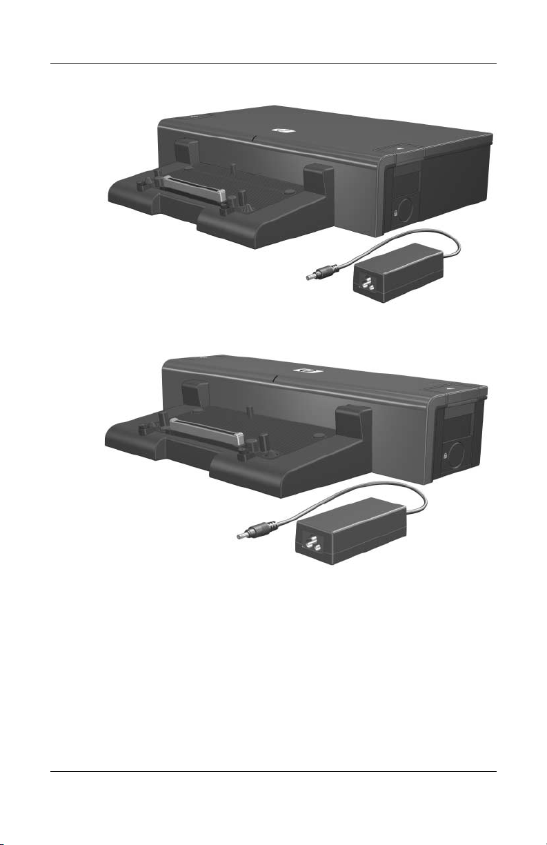
Product Description
HP Advanced Docking Station and HP Smart Adapter
HP Docking Station and HP Smart Adapter
1–2 Maintenance and Service Guide
Page 7

Product Description
The HP Docking Station and HP Advanced Docking Station are
compatible with the following computer models:
■ HP Compaq nc2400 Notebook PC
■ HP Compaq nc4200 and nc4400 Notebook PCs
■ HP Compaq tc4200 and tc4400 Tablet PCs
■ HP Compaq nc6110, nc6120, and nc6140 Notebook PCs
■ HP Compaq nx6110 and nx6120 Notebook PCs
■ HP Compaq nc/nx6115 and nc/nx6125 Notebook PCs
■ HP Compaq nc6220 and nc6230 Notebook PCs
■ HP Compaq nx6320, nc6320, and nx6310 Notebook PCs
■ HP Compaq nx6325 and HP Compaq nx6315 Notebook PCs
■ HP Compaq nc6400 Notebook PC
■ HP Compaq 6510b and 6515b Notebook PCs
■ HP Compaq 6710s, 6710b, 6715s, and 6715b Notebook PCs
■ HP Compaq nx7400 Notebook PC
■ HP Compaq nc8200, nw8200, and nx8200 Notebook PCs
■ HP Compaq nw8440, nc8430, and nx8420 Notebook PCs
■ HP Compaq 8510w and 8510p Notebook PCs
■ HP Compaq 8710w and 8710p Notebook PCs
■ HP Compaq nw9440 and nx9420 Notebook PCs
Maintenance and Service Guide 1–3
Page 8

Product Description
1.1 Fe a t ur es
■ Integrated cable lock slot
■ Security slot (for standard cable lock)
■ HP Smart Adapter external AC adapter (charges docked PC)
■ Lights (power, docking)
■ Integrated MultiBay II (advanced docking station only)
■ MultiBay II activity light (advanced docking station only)
■ ExpressCard slot (advanced docking station only)
■ Dual-link DVI support for following computer models:
❏ HP Compaq 8510p and 8510w Notebook PC
❏ HP Compaq 8710p and 8710w Notebook PC
1–4 Maintenance and Service Guide
Page 9

■ Connectors:
❏ Monitor stand port
❏ External monitor port
❏ Serial port
❏ Parallel port
❏ Keyboard connector
❏ Mouse connector
❏ Audio-out (headphone) jack
❏ Audio-in (microphone) jack
❏ Digital video (DVI) port
❏ Composite video jack
❏ RJ-45/Ethernet (network) jack
❏ RJ-11 (modem) jack
❏ Universal Serial Bus (USB) 2.0 ports
◆ Docking station—3 USB 2.0 ports
◆ Advanced docking station—5 USB 2.0 ports
Product Description
❏ Powered USB port
❏ S-Video-out jack
❏ Power connector
Maintenance and Service Guide 1–5
Page 10
Product Description
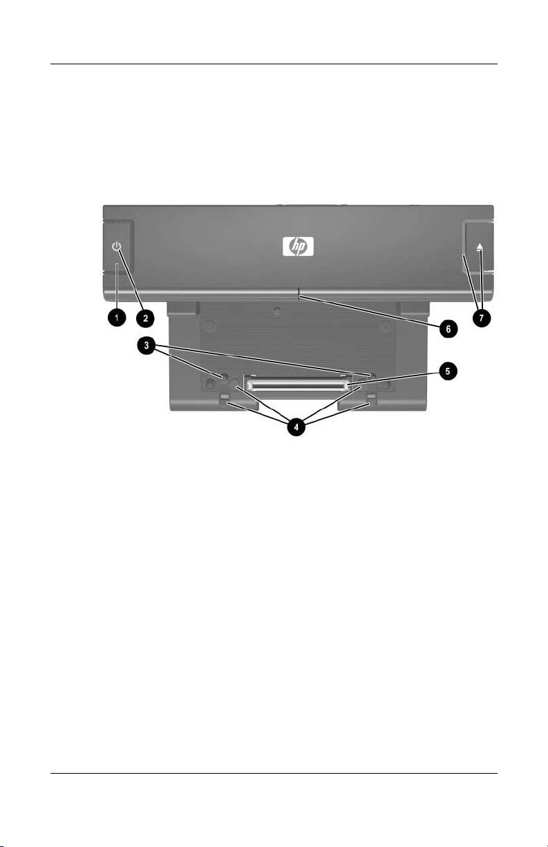
1.2 External Components
The external components on the top of the docking station are
shown in the following illustration and described in Table 1-1.
Top Components, Docking Station
1–6 Maintenance and Service Guide
Page 11

Product Description
Table 1-1
Top Components, Docking Station
Item Component Description
1 Power button Turns on power to the computer.
2 Power light Indicates the state of the computer and is
turned on when the computer is turned on.
3 Docking posts (2) Align and secure the computer for proper
connection to the docking station.
4 Computer eject
mechanisms (4)
5 Docking connector Connects the computer to the
6 Visual alignment
indicator
7 Computer eject button
and docking light
Disconnect the computer from the docking
station when you press the eject button.
docking station.
Helps you correctly align the computer
when connecting it to the docking station.
Ejects the computer from the docking
station. The docking light is turned on when
the computer is properly aligned.
Maintenance and Service Guide 1–7
Page 12
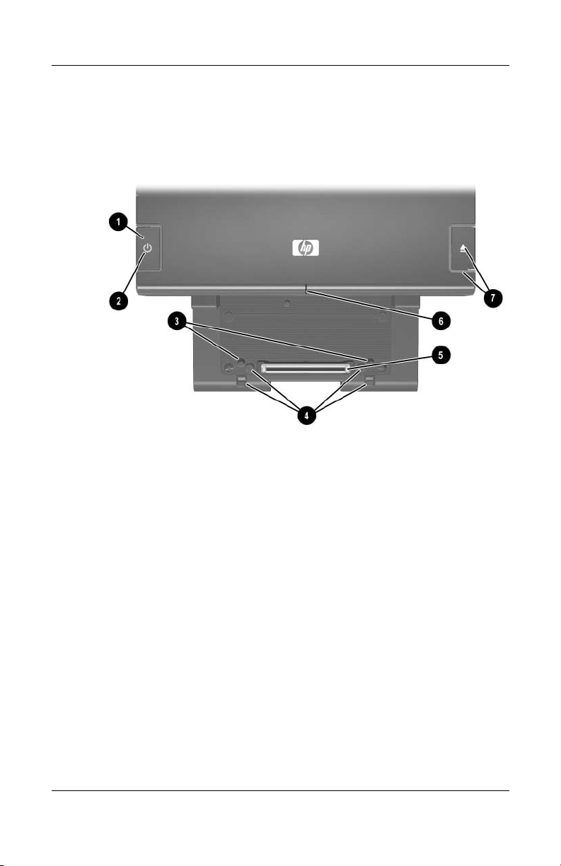
Product Description
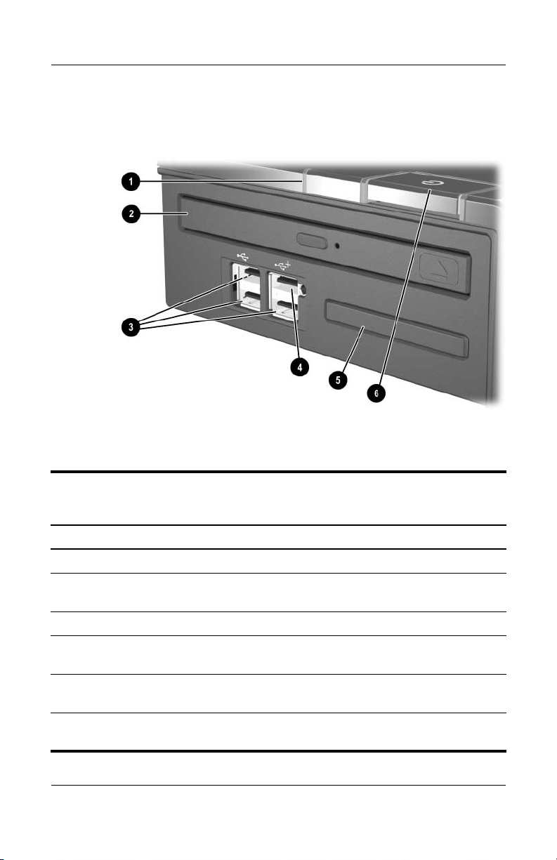
The external components on the top of the advanced docking
station are shown in the following illustration and described in
Table 1-2.
Top Components, Advanced Docking Station
1–8 Maintenance and Service Guide
Page 13

Product Description
Tabl e 1-2
Top Components, Advanced Docking Station
Item Component Description
1 Power button Turns on power to the computer.
2 Power light Indicates the state of the computer and is
turned on when the computer is turned on.
3 Docking posts (2) Align and secure the computer for
proper connection to the docking station.
4 Computer eject
mechanisms (4)
5 Docking connector Connects the computer to the docking
6 Visual alignment
indicator
7 Computer eject button
and docking light
Disconnect the computer from the docking
station when you press the eject button.
station.
Helps you correctly align the computer
when connecting it to the docking station.
Ejects the computer from the docking
station. The docking light is turned on
when the computer is properly aligned.
Maintenance and Service Guide 1–9
Page 14
Product Description
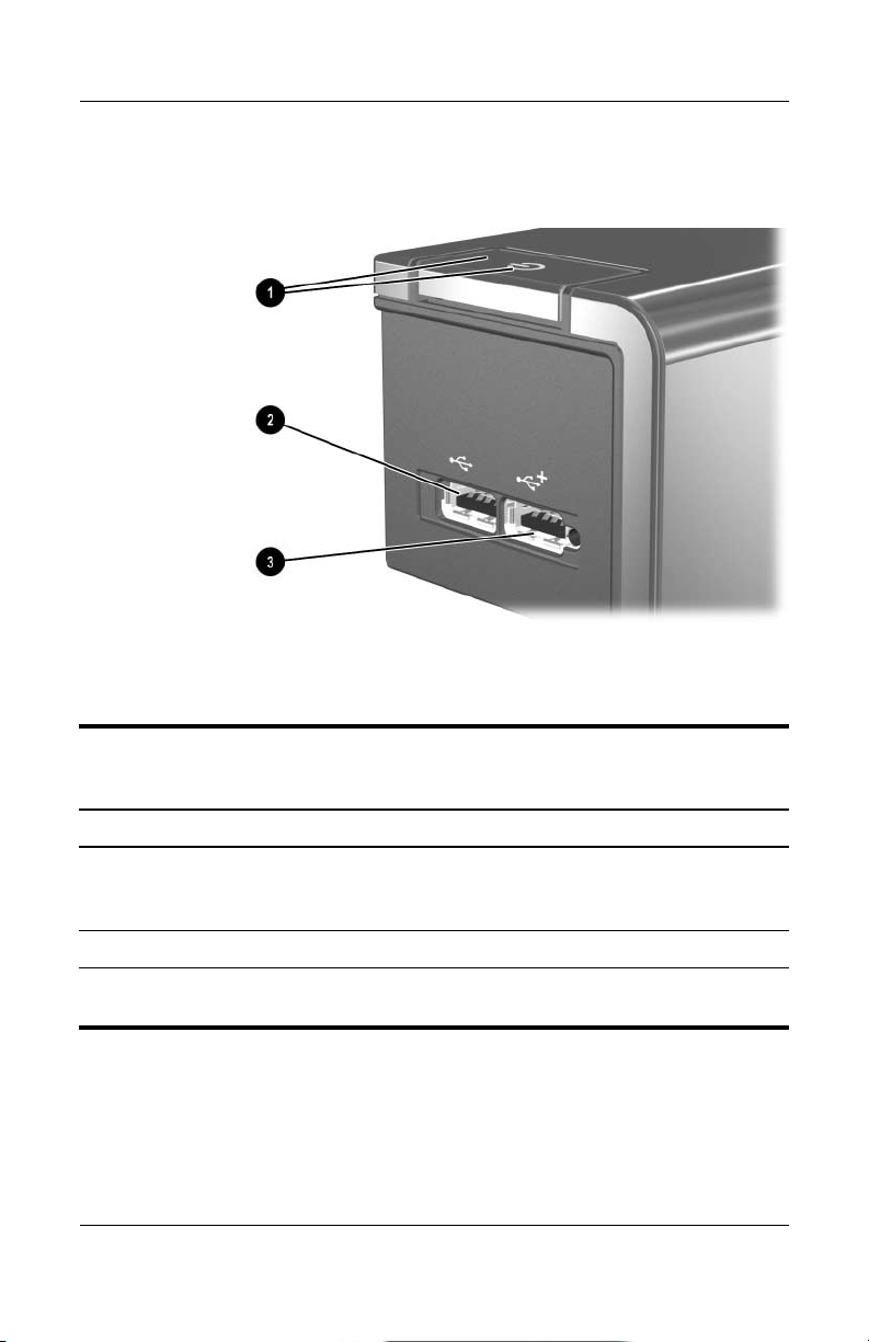
The external components on the left side of the docking station
are shown in the following illustration and described in Table 1-3.
Left-Side Components, Docking Station
Table 1 - 3
Left-Side Components, Docking Station
Item Component Description
1 Power button and
power light
2 USB port Allows you to connect USB devices.
3 Powered USB port Allows you to connect to select USB
1–10 Maintenance and Service Guide
Turns on power to the computer. The light
indicates the state of the computer, and is
turned on when the computer is turned on.
devices.
Page 15
Product Description
The external components on the left side of the advanced docking
station are shown in the following illustration and described in
Table 1-4.
Left-Side Components, Advanced Docking Station
Tabl e 1-4
Left-Side Components, Advanced Docking Station
Item Component Description
1 MultiBay II light Lights to indicate MultiBay II drive activity.
2 MultiBay II Supports 9.5-mm MultiBay II drives
such as hard drives and optical drives.
3 USB ports (3) Allow you to connect USB devices.
4 Powered USB port Allows you to connect to select USB
devices.
5 ExpressCard slot Allows you to connect ExpressCard
devices to the docking station.
6 Power button and
power light
Maintenance and Service Guide 1–11
Turns on power to the computer. The light is
turned on when the computer is turned on.
Page 16
Product Description
The external components on the right side of the docking station
are shown in the following illustration and described in Table 1-5.
Right-Side Components, Docking Station
Table 1-5
Right-Side Components, Docking Station
Item Component Description
1 Computer eject button
and dock light
2 Integrated cable lock slot Supports the cable lock, which secures
1–12 Maintenance and Service Guide
Ejects the computer from the docking
station. The dock light is turned on
when the computer is properly aligned.
the docking station and a connected
computer.
Page 17
Product Description
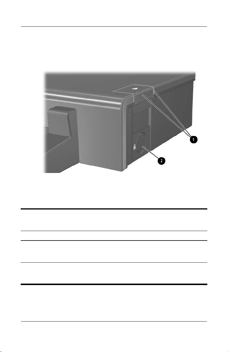
The external components on the right side of the advanced
docking station are in the following illustration below and
described in Table 1-6.
Right-Side Components, Advanced Docking Station
Tabl e 1-6
Right-Side Components, Advanced Docking Station
Item Component Description
1 Computer eject button
and docking light
2 Integrated cable lock slot Supports the cable lock, which secures the
Maintenance and Service Guide 1–13
Ejects the computer from the docking
station. The docking light is turned on when
the computer is properly aligned.
docking station, connected computer, and
MultiBay II drive.
Page 18
Product Description
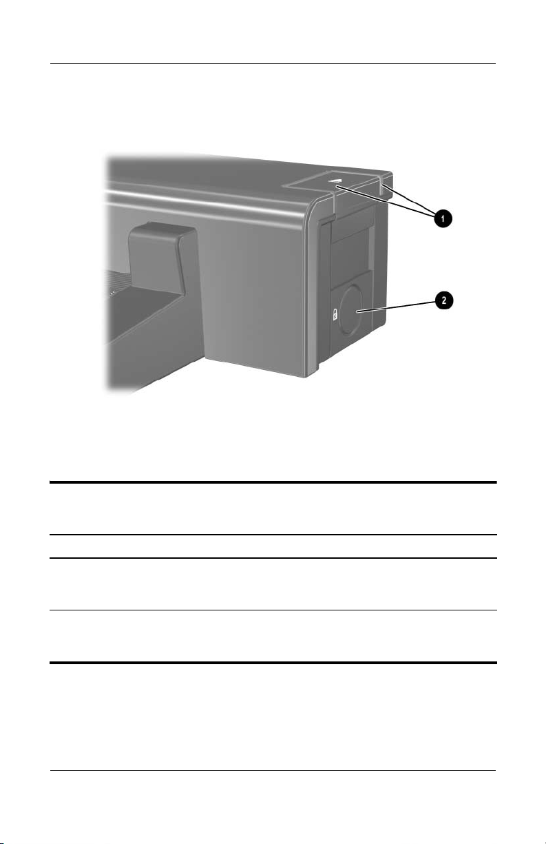
The external components on the rear of the docking station are
shown in the following illustration and described in Table 1-7.
Rear Components, Docking Station
Table 1 - 7
Rear Components, Docking Station
Item Component Description
1 Security cable slot Connects an optional security
cable lock.
2 Monitor stand port Connects an optional HP Monitor Stand
to the docking station.
3 Audio-out (headphone) jack Connects an audio output device such
as headphones or speakers.
4 Mouse connector Connects a PS/2 mouse.
5 Parallel port Connects a parallel device such as
aprinter.
6 Digital video (DVI) jack Connects a DVI device such as a flat
panel monitor.
1–14 Maintenance and Service Guide
Page 19

Product Description
Table 1 - 7
Rear Components, Docking Station
Item Component Description
7 Power light Is turned on when the docking station
is connected to AC power.
8 RJ-11 (modem) jack Connects a telephone cable.
9 RJ-45 (network) jack Connects a network cable.
10 USB ports (2) Connect USB devices.
(Continued)
11 Smart Adapter power
connector
12 External monitor port Connects a VGA monitor.
13 Serial port Connects a serial device such as
14 Keyboard connector Connects a PS/2 keyboard.
15 Audio-in (microphone) jack Connects home audio equipment
16 Composite video jack Connects a composite video device
17 S-Video-out jack Connects an S-Video device such
Connects the docking station to the
HP Smart Adapter AC adapter.
a mouse.
such as CD and MP3 players.
such as a TV.
as a TV, VCR, or camcorder.
Maintenance and Service Guide 1–15
Page 20
Product Description
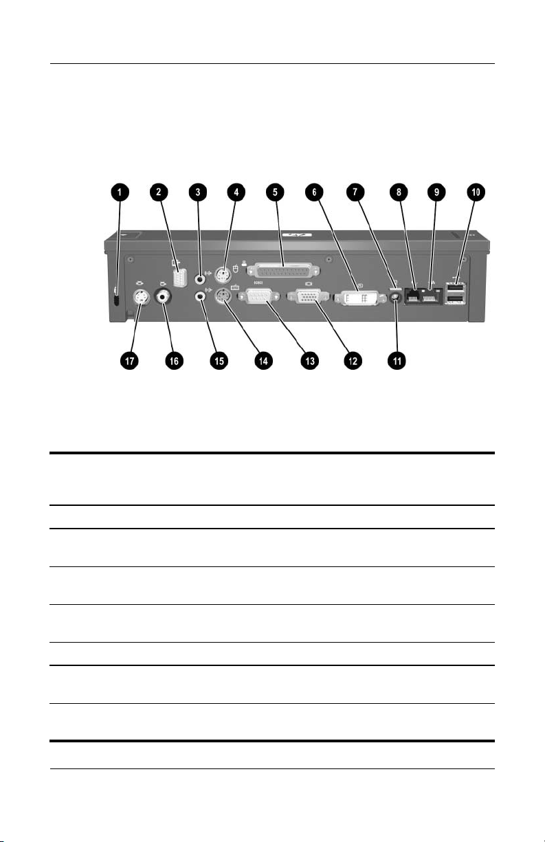
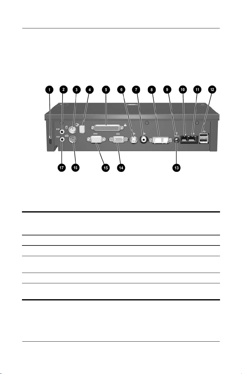
The external components on the rear of the advanced docking
station are shown in the following illustration and described in
Table 1-8.
Rear Components, Advanced Docking Station
Tabl e 1-8
Rear Components, Advanced Docking Station
Item Component Description
1 Security cable slot Connects an optional security cable lock.
2 Audio-out (headphone)
jack
3 Mouse connector Connects a PS/2 mouse.
4 Monitor stand port Connects an optional HP Monitor Stand to
1–16 Maintenance and Service Guide
Connects an audio output device such as
headphones or speakers.
the docking station.
Page 21

Product Description
Tabl e 1-8
Rear Components, Advanced Docking Station
Item Component Description
5 Parallel port Connects a parallel device such as
a printer.
6 S-Video-out jack Connects an S-Video device such as a TV,
VCR, or camcorder.
7 Composite video jack Connects a composite video device such
as a TV.
8 Digital video (DVI) jack Connects a DVI device such as a flat panel
monitor.
9 Power light Is turned on when the docking station
is connected to AC power.
10 RJ-11 (modem) jack Connects a telephone cable.
11 RJ-45 (network) jack Connects a network cable.
12 USB ports (2) Connect USB devices.
(Continued)
13 Smart Adapter power
connector
14 External monitor port Connects a VGA monitor.
15 Serial port Connects a serial device such as a mouse.
16 Keyboard connector Connects a PS/2 keyboard.
17 Audio-in (microphone)
jack
Maintenance and Service Guide 1–17
Connects the docking station to the
HP Smart Adapter AC adapter.
Connects home audio equipment such as
CD and MP3 players.
Page 22

Product Description
1. 3 D e s i g n O ve r vi ew
This section presents a design overview of key parts and features
of the HP Docking Station and HP Advanced Docking Station.
Refer to Chapter 3, “Illustrated Parts Catalog,” to identify
replacement parts, and Chapter 5, “Removal and Replacement
Procedures,” for disassembly steps.
The docking stations provide the following device connections:
■ Monitor stand port, for use with the HP Monitor Stand
■ Digital video (DVI) jack
■ Audio-out (headphone) jack
■ Audio-in (microphone) jack
■ RJ-11 (modem) jack
■ RJ-45 (network) jack
■ USB 2.0 connectors (3 on docking station, 5 on
advanced docking station)
■ Powered USB 2.0 port
■ S-Video out
■ Serial port
■ Parallel port
1–18 Maintenance and Service Guide
Page 23

Troubleshooting
WARNING: Only authorized technicians trained by HP should repair
Å
this equipment. All troubleshooting and repair procedures are detailed
to allow only subassembly-/module-level repair. Because of the
complexity of the individual boards and subassemblies, do not attempt
to make repairs at the component level or modifications to any printed
wiring board. Improper repairs can create a safety hazard. Any
indication of component replacement or printed wiring board
modification may void any warranty or exchange allowances.
This chapter contains troubleshooting information for the
HP Docking Station and HP Advanced Docking Station.
Carefully match the symptoms of the malfunction against the
problem description in the troubleshooting tables to avoid a
misdiagnosis. Refer to Chapter 5 for all removal and replacement
procedures.
Follow these guidelines when troubleshooting:
■ Complete the recommended actions in the order in which
they are given.
2
■ When the problem is resolved, do not complete the remaining
troubleshooting steps.
Maintenance and Service Guide 2–1
Page 24

Troubleshooting
2.1 Troubleshooting Checklist
When troubleshooting a problem, check the following list for
possible solutions before replacing parts:
■ Verify that cables are connected properly to the suspected
defective part.
■ Verify that all required device drivers are installed.
2.2 Problems and Solutions
The following tables list possible problems, the possible cause
of each problem, and the recommended solution.
Docking Problems and Solutions
Problem Possible Cause Solution
The computer is not
properly connected to
the docking station.
The computer is turned
on and properly docked,
but the power light and
dock light are not on.
2–2 Maintenance and Service Guide
The computer may
be properly aligned,
but is not fully seated
or docked in the
docking station.
Power cord is not
plugged into either
the docking station or
the AC outlet.
Press the eject button all the
way in to eject the computer.
Lift the computer away from
the docking station. Then
realign the computer visual
alignment indicator with the
indicator on the docking
station, and reconnect the
computer. Ensure that the
computer is properly aligned
and seated, and fully docked
by gently pressing down on
the computer until you hear a
click. If accessories are
attached, they should now
work properly.
Properly plug in power cord.
Page 25

Troubleshooting
Docking Problems and Solutions
Problem Possible Cause Solution
Some of the ports or
connectors do not work,
even though the docking
light is turned on.
The computer may
be properly aligned,
but is not fully seated
or docked in the
docking station.
(Continued)
Press the eject button all the
way in to eject the computer.
Lift the computer away from
the docking station. Then
realign the computer visual
alignment indicator with the
indicator on the docking
station, and reconnect the
computer. Ensure that the
computer is properly aligned
and seated, and fully docked
by gently pressing down on
the computer until you hear a
click. If accessories are
attached, they should now
work properly.
Maintenance and Service Guide 2–3
Page 26

Troubleshooting
Undocking Problems and Solutions
Problem Possible Cause Solution
The computer will not
disconnect from the
docking station.
The connectors may
be jammed.
The cable lock is in
the locked position.
Press the eject button all the
way in. If the computer does
not disconnect, repeat this
procedure to disconnect the
computer.
Applying excessive
Ä
force may damage
connector pins.
Unlock the cable lock and
then disconnect the
computer.
2–4 Maintenance and Service Guide
Page 27

External Device Problems and Solutions
Problem Possible Cause Solution
A new device is not
recognized as part of
the system.
The computer may
be properly aligned,
but is not fully seated
or docked in the
docking station.
The device cable or
power cord is loose.
Press the eject button all the
way in to eject the computer.
Lift the computer away from
the docking station. Then
realign the computer visual
alignment indicator with the
indicator on the docking
station, and reconnect the
computer. Ensure that the
computer is properly aligned
and seated, and fully docked
by gently pressing down on
the computer until you hear a
click. If accessories are
attached, they should now
be recognized by the
system.
■ Ensure that all cables are
securely connected to the
device and the docking
station.
■ Ensure that all power
cords are securely
connected to the device
or docking station and
to an AC outlet.
Troubleshooting
The device was
connected while the
system was on.
Cabling is incorrect. Ensure that the device cable
You may need to
install device drivers
on the computer.
Maintenance and Service Guide 2–5
Turn off the computer, turn
on the device (if applicable),
and then restart the
computer.
is in the correct connector on
the docking station.
Install drivers according to
the device manufacturer’s
instructions.
Page 28

Troubleshooting
Optical Drive Problems and Solutions
Problem Possible Cause Solution
The system cannot read
the optical disc.
The system cannot eject
the media tray.
The disc is not
properly seated
in the drive tray.
The disc is upside
down.
The disc may be dirty
or scratched.
The disc is not
properly seated
in the media tray.
There is no power to
the advanced
docking station.
Remove the disc, reseat it in
the drive tray, and then close
the drive tray.
Remove the disc, turn it over,
and then close the drive tray.
Clean or replace the disc.
Turn off the computer, and
then manually eject the
media tray.
■ Turn on power to the
system, and then eject
the disc.
■ Manually eject the disc.
MultiBay II Problems and Solutions
Problem Possible Cause Solution
The MultiBay II drive is
not recognized.
The drive is not
properly inserted in
the MultiBay II.
The drive was
inserted while the
power was on.
Remove the drive, and then
reinsert it.
Restart the computer while
the drive is in the MultiBay II.
2–6 Maintenance and Service Guide
Page 29

Illustrated Parts Catalog
This chapter provides an illustrated parts breakdown and a
reference for spare part numbers and option part numbers.
3.1 Serial Number Location
When ordering parts or requesting information, provide the
docking station serial number and model number located on
the bottom of the base plate.
3
Serial Number Location
Maintenance and Service Guide 3–1
Page 30

Illustrated Parts Catalog
3.2 Major Components
Major Components, HP Docking Station and
HP Advanced Docking Station
3–2 Maintenance and Service Guide
Page 31

Illustrated Parts Catalog
Table 3 - 1
HP Docking Station/HP Advanced Docking Station
Major Components
Spare Part
Item Description
Number
1 HP Docking Station
(whole unit replacement)
2 HP Advanced Docking Station
(whole unit replacement)
3 Power cord
For use in Australia
For use in Brazil
For use in Denmark
For use in Europe, Middle East, and Africa
For use in Italy
For use in Japan
For use in Korea
For use in Switzerland
For use in the United Kingdom
For use in the United States
4 AC adapter
Smart Adapter AC adapter, 135-W, PFC
Smart Adapter AC adapter, 120-W, PFC
449720-001
449721-001
246959-011
246959-201
246959-081
246959-021
246959-061
246959-291
246959-AD1
246959-AG1
246959-031
246959-001
397803-001
391174-001
Maintenance and Service Guide 3–3
Page 32

Illustrated Parts Catalog
3.3 Miscellaneous Spares Kit
Miscellaneous Spares Kit
3–4 Maintenance and Service Guide
Page 33

Illustrated Parts Catalog
Table 3 - 2
Miscellaneous Plastics Kit
Spare Part
Item Description
Miscellaneous Plastics Kit, includes: 380089-001
1 MultiBay II dummy card
2 ExpressCard slot dummy card
3 Large rubber feet, 5 each
4 Small rubber feet, 2 each
5 Rubber bumper (protects unit and computer when docking)
6 Cable lock bezel blank
7Cable lock bezel
Number
Maintenance and Service Guide 3–5
Page 34

Illustrated Parts Catalog
3.4 Sequential Part Number Listing
Table 3 - 3
Sequential Part Number Listing
Spare Part
Number Description
246959-001 Power cord for use in the United States
246959-011 Power cord for use in Australia
246959-021 Power cord for use in Europe, the Middle East,
246959-031 Power cord for use in the United Kingdom
246959-061 Power cord for use in Italy
246959-081 Power cord for use in Denmark
246959-201 Power cord for use in Brazil
246959-291 Power cord for use in Japan
246959-AD1 Power cord for use in Korea
246959-AG1 Power cord for use in Switzerland
380089-001 Miscellaneous Plastics Kit
391174-001 AC adapter, 120-W, PFC
397803-001 AC adapter, 135-W, PFC
449720-001 HP Docking Station
449721-001 HP Advanced Docking Station
and Africa
3–6 Maintenance and Service Guide
Page 35

Removal and Replacement
This chapter provides essential information for proper and safe
removal and replacement service.
4.1 Tools Required
You will need the following tools to complete the removal and
replacement procedures:
■ Magnetic screwdriver
■ Phillips P0 screwdriver
■ 5.0-mm hex socket for system board standoffs
■ Flat-bladed screwdriver
■ Tool kit (includes connector removal tool, loopback plugs,
and case utility tool)
4
Preliminaries
4.2 Service Considerations
The following sections include some of the considerations that
you should keep in mind during disassembly and assembly
procedures.
As you remove each subassembly from the docking base, place
✎
the subassembly (and all accompanying screws) away from the
work area to prevent damage.
Maintenance and Service Guide 4–1
Page 36

Removal and Replacement Preliminaries
Plastic Parts
Using excessive force during disassembly and reassembly can
damage plastic parts. Use care when handling the plastic parts.
Apply pressure only at the points designated in the maintenance
instructions.
Cables and Connectors
CAUTION: When servicing the expansion base, ensure that cables are
Ä
placed in their proper locations during the reassembly process.
Improper cable placement can damage the expansion base.
Cables must be handled with extreme care to avoid damage.
Apply only the tension required to unseat or seat the cables
during removal and insertion. Handle the cables by the connector
whenever possible. In all cases, avoid bending, twisting, or
tearing cables. Ensure that the cables are routed in such a way that
they cannot be caught or snagged by parts being removed or
replaced. Handle flex cables with extreme care; these cables
tear easily.
4.3 Preventing Electrostatic Damage
Many electronic components are sensitive to electrostatic
discharge (ESD). Circuitry design and structure determine the
degree of sensitivity. Networks built into many integrated circuits
provide some protection, but in many cases, the discharge
contains enough power to alter device parameters or melt silicon
junctions.
A sudden discharge of static electricity from a finger or other
conductor can destroy static-sensitive devices or microcircuitry.
Often the spark is neither felt nor heard, but damage occurs.
An electronic device exposed to electrostatic discharge might not
be affected at all and can work perfectly throughout a normal
cycle. Or the device might function normally for a while, and then
degrade in the internal layers, reducing its life expectancy.
4–2 Maintenance and Service Guide
Page 37

Removal and Replacement Preliminaries
4.4 Packaging and Transporting Precautions
Use the following grounding precautions when packaging and
transporting equipment:
■ To avoid hand contact, transport products in static-safe
containers, such as tubes, bags, or boxes.
■ Protect all electrostatic-sensitive parts and assemblies with
conductive or approved containers or packaging.
■ Keep electrostatic-sensitive parts in their containers until
the parts arrive at static-free workstations.
■ Place items on a grounded surface before removing them
from their containers.
■ Always be properly grounded when touching a sensitive
component or assembly.
■ Store reusable electrostatic-sensitive parts from assemblies
in protective packaging or nonconductive foam.
■ Use transporters and conveyors made of antistatic belts and
roller bushings. Ensure that mechanized equipment used to
move materials is wired to ground and that proper materials
are selected to avoid static charging. When grounding is not
possible, use an ionizer to dissipate electric charges.
Maintenance and Service Guide 4–3
Page 38

Removal and Replacement Preliminaries
4.5 Workstation Precautions
Use the following grounding precautions at workstations:
■ Cover the workstation with approved static-shielding material
(refer to Table 4-2, "Static-Shielding Materials").
■ Use a wrist strap connected to a properly grounded work
surface and use properly grounded tools and equipment.
■ Use conductive field service tools, such as cutters,
screwdrivers, and vacuums.
■ When using fixtures that must directly contact dissipative
surfaces, only use fixtures made of static-safe materials.
■ Keep the work area free of nonconductive materials, such as
ordinary plastic assembly aids and Styrofoam.
■ Handle electrostatic-sensitive components, parts, and
assemblies by the case or PCM laminate. Handle these items
only at static-free workstations.
■ Avoid contact with pins, leads, or circuitry.
■ Turn off power and input signals before inserting or removing
connectors or test equipment.
4.6 Grounding Equipment and Methods
Grounding equipment must include either a wrist strap or a foot
strap at a grounded workstation.
■ When seated, wear a wrist strap connected to a grounded
system. Wrist straps are flexible straps with a minimum of
one megohm ±10% resistance in the ground cords. To
provide proper ground, wear a strap snugly against the skin
at all times. On grounded mats with banana-plug connectors,
use alligator clips to connect a wrist strap.
4–4 Maintenance and Service Guide
Page 39

Removal and Replacement Preliminaries
■ When standing, use foot straps and a grounded floor mat.
Foot straps (heel, toe, or boot straps) can be used at standing
workstations and are compatible with most types of shoes
or boots. On conductive floors or dissipative floor mats, use
foot straps on both feet with a minimum of one megohm
resistance between the operator and ground. To be effective,
the conductive strips must be worn in contact with the skin.
Other grounding equipment recommended for use in preventing
electrostatic damage includes
■ Antistatic tape.
■ Antistatic smocks, aprons, and sleeve protectors.
■ Conductive bins and other assembly or soldering aids.
■ Nonconductive foam.
■ Conductive tabletop workstations with ground cords of
one megohm resistance.
■ Static-dissipative tables or floor mats with hard ties to
the ground.
■ Field service kits.
■ Static awareness labels.
■ Material-handling packages.
■ Nonconductive plastic bags, tubes, or boxes.
■ Metal tote boxes.
■ Electrostatic voltage levels and protective materials.
Maintenance and Service Guide 4–5
Page 40

Removal and Replacement Preliminaries
Table 4-1 shows how humidity affects the electrostatic voltage
levels generated by different activities.
Tabl e 4-1
Typical Electrostatic Voltage Levels
Relative Humidity
Event 10% 40% 55%
Walking across carpet 35,000 V 15,000 V 7,500 V
Walking across vinyl floor 12,000 V 5,000 V 3,000 V
Motions of bench worker 6,000 V 800 V 400 V
Removing DIPS from plastic tube 2,000 V 700 V 400 V
Removing DIPS from vinyl tray 11,500 V 4,000 V 2,000 V
Removing DIPS from Styrofoam 14,500 V 5,000 V 3,500 V
Removing bubble pack from PCB 26,500 V 20,000 V 7,000 V
Packing PCBs in foam-lined box 21,000 V 11,000 V 5,000 V
A product can be degraded by as little as 700 V.
✎
Table 4-2 lists the shielding protection provided by antistatic bags
and floor mats.
Table 4 - 2
Static-Shielding Materials
Material Use Voltage Protection Level
Antistatic plastic Bags 1,500 V
Carbon-loaded plastic Floor mats 7,500 V
Metallized laminate Floor mats 5,000 V
4–6 Maintenance and Service Guide
Page 41

Removal and Replacement
This chapter provides removal and replacement procedures.
You must remove up to three screws (for the cable lock) when
servicing the docking station. Make note of each screw location
during removal and replacement.
Refer to Appendix A, “Screw Listing,” for detailed information
on screw sizes, locations, and usage.
5.1 Serial Number
Report the docking station serial number to HP when requesting
information or ordering spare parts. The serial number is located
on the bottom of the docking station.
5
Procedures
Serial Number Location
Maintenance and Service Guide 5–1
Page 42

Removal and Replacement Procedures
5.2 Preparing the Docking Station for Disassembly
Perform the following steps before disassembling the
docking station:
1. If a computer is connected to the docking station, close the
computer. If you close the computer with the power turned
on, the computer may enter Standby mode. To resume
operation after undocking, open the computer, and then press
the power button.
Closing the Computer
5–2 Maintenance and Service Guide
Page 43

Removal and Replacement Procedures
2. Press the eject button 1. The computer disconnects from
the docking station.
3. Lift up the computer 2 and set it aside.
Undocking the Computer
4. Disconnect all external devices connected to the
docking station.
5. Disconnect the power cord from the docking station.
Maintenance and Service Guide 5–3
Page 44

Removal and Replacement Procedures
5.3 Installing the Cable Lock
Security solutions are designed to act as deterrents. These
✎
deterrents may not prevent a product from being mishandled
or stolen.
The cable lock allows you to secure the docking station and a
docked computer, or the advanced docking station with a docked
computer and MultiBay II drive installed.
Install the cable lock into the integrated cable lock slot on the
right side of the docking station, as shown in the following
illustrations.
Identifying the Cable Lock Slot
5–4 Maintenance and Service Guide
Page 45

Removal and Replacement Procedures
To install the cable lock:
1. Loop the cable around a stationary object.
2. Turn the docking station upside down, and then remove the
three PM2.5x5 screws from the cable lock bezel 1.
3. Remove the bezel from the docking station 2, and
then remove the bezel blank from the cable lock bezel 3.
Removing the Cable Lock Bezel and Bezel Blank
Maintenance and Service Guide 5–5
Page 46

Removal and Replacement Procedures
4. With the lock and key in the unlocked position and the t-bar
on the back of the lock in the vertical position, insert the lock
into the center groove in the cable lock slot in the docking
station 1.
5. Insert the cable into the recessed cable channel in the base
of the docking station 2.
Inserting the Cable Lock
5–6 Maintenance and Service Guide
Page 47

Removal and Replacement Procedures
6. Turn the key counterclockwise to lock 1.
7. Remove the key from the lock 2.
8. Reinsert the cable lock bezel onto the docking station 3.
9. Replace the screws to secure the bezel 4.
Securing the Cable Lock
Maintenance and Service Guide 5–7
Page 48

Removal and Replacement Procedures
The following illustration shows a docking station with the
cable lock installed.
Docking Station with Cable Lock Inserted
5–8 Maintenance and Service Guide
Page 49

This chapter provides physical and performance specifications.
Dimensions
6
Specifications
Tabl e 6-1
HP Docking Station Specifications
Height
Width
Length
Weight
Tem pe rature
Operating
Nonoperating
Relative humidity (noncondensing)
Operating
Nonoperating
Power Supply
Rated Voltage
Rated Current
Line Frequency
28.0 cm
6.1 cm
15.3 cm
1.02 kg 2.24 lb
10°C to 35°C
-10°C to 60°C
10% to 90%
5% to 90%, 38.7°C (101.6°F) maximum wet
bulb temperature
100 to 240V
2.5A rms
50 - 60 Hz
11.02 in
2.40 in
6.02 in
50°F to 95°F
14°F to 140°F
Maintenance and Service Guide 6–1
Page 50

Specifications
Tabl e 6-1
HP Docking Station Specifications
Altitude
Operating
Non-operating
Shock
Operating
Non-operating
Vibration
Operating
Non-operating
(Continued)
0 m to 3,048 m
0 m to 9,144 m
10 G, 11 ms, half-sine
60 G, 11 ms, half-sine
0.5 G zero-to-peak, 10 to 500 Hz, 0.25 oct/min
sweep rate
1 G, zero-to-peak, 10 to 500 Hz, 0.5 oct/min
sweep rate
0 ft to 10,000 ft
0 ft to 30,000 ft
6–2 Maintenance and Service Guide
Page 51

HP Advanced Docking Station Specifications
Dimensions
Specifications
Tabl e 6-2
Height
Width
Length
Weight
Tem pe rature
Operating
Nonoperating
Relative humidity (noncondensing)
Operating
Nonoperating
Power Supply
Rated Voltage
Rated Current
Line Frequency
28.0 cm
6.1 cm
24.3 cm
1.78 kg 3.93 lb
10°C to 35°C
-10°C to 60°C
10% to 90%
5% to 90%, 38.7°C (101.6°F) maximum wet
bulb temperature
100 to 240V
2.5A rms
50 - 60 Hz
11.02 in
2.40 in
9.56 in
50°F to 95°F
14°F to 140°F
Maintenance and Service Guide 6–3
Page 52

Specifications
Tabl e 6-2
HP Advanced Docking Station Specifications
Altitude
Operating
Non-operating
Shock
Operating
Non-operating
Vibration
Operating
Non-operating
0 m to 3,048 m
0 m to 9,144 m
10 G, 11 ms, half-sine
60 G, 11 ms, half-sine
0.5 G zero-to-peak, 10 to 500 Hz, 0.25 oct/min
sweep rate
1 G, zero-to-peak, 10 to 500 Hz, 0.5 oct/min
sweep rate
0 ft to 10,000 ft
0 ft to 30,000 ft
(Continued)
6–4 Maintenance and Service Guide
Page 53

A
Screw Listing
This appendix provides specification and reference information
for the screws used in the HP Docking Station and the
HP Advanced Docking Station.
Maintenance and Service Guide A–1
Page 54

Screw Listing
Table A - 1
Phillips M2.5×5.0 Screw
mm
Where used:
Three screws that secure the cable lock cover to the base enclosure
(documented in Section 5.3)
Color Qty. Length Thread
Black 3 5.0 mm 2.5 mm 4.0 mm
Head
Width
Phillips M2.5×5.0 Screw Locations
A–2 Maintenance and Service Guide
Page 55

Connector Pin Assignments
Table B - 1
Audio-In (Microphone) Jack
Pin Signal Pin Signal
1 Audio signal in 3 Ground
2 Audio signal in
B
Maintenance and Service Guide B–1
Page 56

Connector Pin Assignments
Table B - 2
Audio-Out (Headphone) Jack
Pin Signal Pin Signal
1 Audio out, left channel 3 Ground
2 Audio out, right channel
B–2 Maintenance and Service Guide
Page 57

Connector Pin Assignments
Table B - 3
External Monitor Port
Pin Signal Pin Signal
1 Red analog 9 +5 VDC
2 Green analog 10 Ground
3 Blue analog 11 Monitor detect
4 Not connected 12 DDC 2B data
5 Ground 13 Horizontal sync
6 Ground analog 14 Vertical sync
7 Ground analog 15 DDC 2B clock
8 Ground analog
Maintenance and Service Guide B–3
Page 58

Connector Pin Assignments
Table B - 4
Keyboard/Mouse Connector
Pin Signal Pin Signal
1 Keyboard/mouse DATA 4 +5 VDC
2 Keyboard/mouse DATA 5 Keyboard/mouse CLK
3 Ground 6 Keyboard/mouse CLK
B–4 Maintenance and Service Guide
Page 59

Connector Pin Assignments
Table B - 5
Parallel Port
Pin Signal Pin Signal
1 Strobe 14 Auto linefeed
2 Data bit 0 15 Error
3 Data bit 1 16 Initialize printer
4 Data bit 2 17 Select in
5 Data bit 3 18 Ground
6 Data bit 4 19 Ground
7 Data bit 5 20 Ground
8 Data bit 6 21 Ground
9 Data bit 7 22 Ground
10 Acknowledge 23 Ground
11 Busy 24 Ground
12 Paper end 25 Ground
13 Select
Maintenance and Service Guide B–5
Page 60

Connector Pin Assignments
Table B - 6
RJ-11 (Modem) Jack
Pin Signal Pin Signal
1 Unused 4 Unused
2Tip 5Unused
3 Ring 6 Unused
Table B - 7
RJ-45 (Network) Jack
Pin Signal Pin Signal
1 Transmit + 5 Unused
2 Transmit – 6 Receive –
3 Receive + 7 Unused
4 Unused 8 Unused
B–6 Maintenance and Service Guide
Page 61

Connector Pin Assignments
Table B - 8
Serial Port
Pin Signal Pin Signal
1 Carrier detect 6 Data set ready
2 Receive data 7 Ready to send
3 Transmit data 8 Clear to send
4 Data terminal ready 9 Ring indicator
5Ground
Maintenance and Service Guide B–7
Page 62

Connector Pin Assignments
Table B - 9
S-Video-Out Jack
Pin Signal Pin Signal
1 TV-Ground 5 TV-CD
2 TV-CVBS 6 TV-Ground
3 TV-Ground 7 TV-YD
4 TV-Ground
Table B-10
Universal Serial Bus Port
Pin Signal Pin Signal
1 +5 VDC 3 Data +
2 Data – 4 Ground
B–8 Maintenance and Service Guide
Page 63

Power Cord Set Requirements
3-Conductor Power Cord Set
The wide range input feature of the docking station permits it
to operate from any line voltage from 100 to 120 or 220 to 240
volts AC.
The power cord set included with the docking station meets the
requirements for use in the country or region where the
equipment is purchased.
Power cord sets for use in other countries or regions must meet
the requirements of the country or region where the docking
station is used.
C
Maintenance and Service Guide C–1
Page 64

Power Cord Set Requirements
General Requirements
The requirements listed below are applicable to all countries or
regions.
■ The length of the power cord set must be at least 1.5 m
(5.0 ft) and a maximum of 2.0 m (6.5 ft).
■ All power cord sets must be approved by an acceptable
accredited agency responsible for evaluation in the country or
region where the power cord set will be used.
■ The power cord sets must have a minimum current capacity
of 10 amps and a nominal voltage rating of 125 or 250 V AC,
as required by each country’s or region’s power system.
■ The appliance coupler must meet the mechanical
configuration of an EN 60 320/IEC 320 Standard Sheet C13
connector for mating with the appliance inlet on the back of
the docking station.
C–2 Maintenance and Service Guide
Page 65

Power Cord Set Requirements
Country/Region Specific Requirements
3-Conductor Power Cord Set Requirements
Country/Region Accredited Agency Applicable Note Number
Australia EANSW 1
Austria OVE 1
Belgium CEBC 1
Canada CSA 2
Denmark DEMKO 1
Finland FIMKO 1
France UTE 1
Germany VDE 1
Italy IMQ 1
Japan METI 3
NOTES:
✎
1. The flexible cord must be <HAR> Type HO5VV-F, 3-conductor, 1.0 mm²
conductor size. Power cord set fittings (appliance coupler and wall plug)
must bear the certification mark of the agency responsible for evaluation
in the country or region where it will be used.
2. The flexible cord must be Type SPT-3 or equivalent, No. 18 AWG,
3-conductor. The wall plug must be a two-pole grounding type with a
NEMA 5-15P (15 A, 125 V) or NEMA 6-15P (15 A, 250 V) configuration.
3. The appliance coupler, flexible cord, and wall plug must bear a “T” mark and
registration number in accordance with the Japanese Dentori Law. The
flexible cord must be Type VCT or VCTF, 3-conductor, 1.00 mm² conductor
size. The wall plug must be a two-pole grounding type with a Japanese
Industrial Standard C8303 (7 A, 125 V) configuration.
Maintenance and Service Guide C–3
Page 66

Power Cord Set Requirements
3-Conductor Power Cord Set Requirements
Country/Region Accredited Agency Applicable Note Number
Korea EK 4
The Netherlands KEMA 1
Norway NEMKO 1
People’s Republic
of China
Sweden SEMKO 1
Switzerland SEV 1
Taiwan BSMI 4
United Kingdom BSI 1
United States UL 2
NOTES:
✎
1. The flexible cord must be <HAR> Type HO5VV-F, 3-conductor, 1.0 mm²
conductor size. Power cord set fittings (appliance coupler and wall plug)
must bear the certification mark of the agency responsible for evaluation
in the country or region where it will be used.
2. The flexible cord must be Type SPT-3 or equivalent, No. 18 AWG,
3-conductor. The wall plug must be a two-pole grounding type with a
NEMA 5-15P (15 A, 125 V) or NEMA 6-15P (15 A, 250 V) configuration.
3. The appliance coupler, flexible cord, and wall plug must bear a “T” mark and
registration number in accordance with the Japanese Dentori Law. The
flexible cord must be Type VCT or VCTF, 3-conductor, 1.00 mm² conductor
size. The wall plug must be a two-pole grounding type with a Japanese
Industrial Standard C8303 (7 A, 125 V) configuration.
4. The flexible cord must be Type RVV, 3-conductor, 0.75 mm² conductor size.
Power cord set fittings (appliance coupler and wall plug) must bear
the certification mark of the agency responsible for evaluation in the country
or region where it will be used.
5. The flexible cord must be Type VCTF, 3-conductor, 0.75 mm² conductor
size. Power cord set fittings (appliance coupler and wall plug) must bear the
certification mark of the agency responsible for evaluation in the country or
region where it will be used.
CCC 5
(Continued)
C–4 Maintenance and Service Guide
Page 67

Index
A
AC adapter, spare part number
3–3, 3–6
advanced docking station
spare part number
specifications
See also docking station
audio-in jack
location
pin assignments
audio-out jack
location
pin assignments
1–15, 1–17
1–14, 1–16
3–3, 3–6
6–3
B–1
B–2
B
bumper, spare part number
3–5
C
cable lock bezel blank, spare
part number
cable lock bezel, spare part
number
cable lock slot
cables, service considerations
4–2
3–5
3–5
1–12, 1–13
components
left-side
rear panel
right-side
top
composite video jack
1–17
computer eject button
1–9, 1–12, 1–13
computer eject mechanisms
1–7, 1–9
connection troubleshooting
2–2, 2–3
connector pin assignments
audio-in jack
audio-out jack
external monitor port
headphone jack
keyboard connector
microphone jack
modem jack
monitor port
mouse connector
network jack
parallel port
1–10, 1–11
1–14, 1–16
1–12, 1–13
1–6, 1–8
B–6
B–5
1–15,
1–7,
B–1
B–2
B–3
B–2
B–4
B–1
B–3
B–4
B–6
Maintenance and Service Guide Index–1
Page 68

Index
RJ-11 jack B–6
RJ-45 jack
serial port
S-Video-out jack
Universal Serial Bus (USB)
port
connectors, service
considerations
B–6
B–7
B–8
B–8
4–2
D
design overview 1–18
digital video jack
disconnection troubleshooting
2–4, 2–5
docking connector
docking light
docking posts
docking problems
docking station
spare part number
specifications
See also advanced docking
station
dummy card
ExpressCard
MultiBay II
DVI jack
1–14, 1–17
1–14, 1–17
1–7, 1–9
1–7, 1–9, 1–12
1–7, 1–9
2–2, 2–3
3–3, 3–6
6–1
3–5
3–5
E
electrostatic discharge 4–2,
4–6
ExpressCard slot
dummy card
location
external device problems
3–5
1–11
2–5
external monitor port
location
pin assignments
1–15, 1–17
F
features 1–4
feet, spare part number
G
grounding equipment and
methods
4–4
H
headphone jack
location
pin assignments
1–14, 1–16
I
illustrated parts catalog 3–1
K
keyboard connector 1–17
location
pin assignments
1–15
L
left-side components 1–10,
1–11
M
major components 3–2
microphone jack
location
pin assignments
Miscellaneous Plastics Kit
contents
spare part number
1–15, 1–17
3–4, 3–5
3–5, 3–6
B–3
3–5
B–2
B–4
B–1
3–4,
Index–2 Maintenance and Service Guide
Page 69

Index
modem jack
location
pin assignments
monitor port
location
pin assignments
monitor stand port
mouse connector
location
pin assignments
MultiBay II
dummy card
light
problems
1–15, 1–17
B–6
1–15, 1–17
B–3
1–14, 1–16
1–14, 1–16
B–4
1–11
3–5
1–11
2–6
N
network jack
location
pin assignments
1–15, 1–17
B–6
O
optical drive problems 2–6
P
packing precautions 4–3
parallel port
location
pin assignments
parts list
plastic parts
power button
1–11
power connector
power cord
set requirements
spare part number
1–14, 1–17
B–5
3–1
4–2
1–7, 1–9, 1–10,
1–15, 1–17
C–2
3–3, 3–6
power light
1–11, 1–15, 1–17
preliminaries
removal
replacement
troubleshooting checklist
1–7, 1–9, 1–10,
4–1
4–1
2–2
R
rear panel components 1–14,
1–16
removal and replacement
procedures
right-side components
1–13
RJ-11 jack
location
pin assignments
RJ-45 jack
location
pin assignments
rubber bumper, spare part
number
rubber feet, spare part number
3–5
5–1
1–12,
1–15, 1–17
B–6
1–15, 1–17
B–6
3–5
S
screw listing A–1
security cable slot
serial number
serial port
location
pin assignments
service considerations
spare part number
advanced docking station
3–3, 3–6
1–14, 1–16
3–1, 5–1
1–15, 1–17
B–7
4–1
Maintenance and Service Guide Index–3
Page 70

Index
docking station 3–3, 3–6
Miscellaneous Plastics Kit
3–4
power cord
specifications
advanced docking station
6–3
docking station
static-shielding materials
S-Video-out jack
location
pin assignments
3–3
6–1
4–6
1–15, 1–17
B–8
T
tools required 4–1
top components
transporting precautions
troubleshooting checklist
1–6, 1–8
4–3
2–1
U
undocking problems 2–4
undocking the computer
Universal Serial Bus (USB)
port
location
pin assignments
1–10, 1–11, 1–15,
1–17
5–3
B–8
V
video jack 1–15, 1–17
visual alignment indicator
1–7, 1–9
W
workstation precautions 4–4
Index–4 Maintenance and Service Guide
 Loading...