

Page 1

HP Jet Fusion 580 Color 3D Printer
Product Documentation
User Guide
Page 2

© Copyright 2018–2019 HP Development
Company, L.P.
Edition 5
Legal notices
The information contained herein is subject to
change without notice.
The only warranties for HP products and
services are set forth in the express warranty
statement accompanying such products and
services. Nothing herein should be construed as
constituting an additional warranty. HP shall not
be liable for technical or editorial errors or
omissions contained herein.
Safety notice
Read and follow the operating and safety
instructions before turning on the printer.
Page 3

Table of contents
1 Welcome to your MJF system ................................................................................................................................................................. 1
Documentation ......................................................................................................................................................................... 2
Product usage requirements .................................................................................................................................................. 2
MJF technology ......................................................................................................................................................................... 2
Usage recommendations ........................................................................................................................................................ 3
2 Safety precautions .................................................................................................................................................................................... 5
Introduction ............................................................................................................................................................................... 6
General safety guidelines ........................................................................................................................................................ 6
Final parts/builds ...................................................................................................................................................................... 7
Explosion hazard ...................................................................................................................................................................... 7
Electrical shock hazard ............................................................................................................................................................ 8
Heat hazard ............................................................................................................................................................................... 8
Fire hazard ................................................................................................................................................................................. 8
Mechanical hazard .................................................................................................................................................................... 9
Light radiation hazard .............................................................................................................................................................. 9
Chemical hazard ....................................................................................................................................................................... 9
Ventilation ............................................................................................................................................................................... 10
Air conditioning ....................................................................................................................................................................... 10
Sound pressure level ............................................................................................................................................................. 10
Printer transport hazard ....................................................................................................................................................... 10
3D part retrieval ..................................................................................................................................................................... 10
Personal protective equipment ........................................................................................................................................... 10
Use of tools ............................................................................................................................................................................. 11
Warnings and cautions .......................................................................................................................................................... 11
Warning labels ........................................................................................................................................................................ 11
Emergency stop button ........................................................................................................................................................ 13
3 Main components ................................................................................................................................................................................... 14
Printer ...................................................................................................................................................................................... 15
Front panel .............................................................................................................................................................................. 16
Set the administrator password .......................................................................................................................................... 19
Software .................................................................................................................................................................................. 19
ENWW iii
Page 4

4 Power on and o .................................................................................................................................................................................... 21
Turn the printer on and o ................................................................................................................................................... 21
Main power switch ................................................................................................................................................................. 22
Away mode ............................................................................................................................................................................. 23
5 Printer networking ................................................................................................................................................................................. 24
Introduction ............................................................................................................................................................................. 24
Connectivity requirement and remote monitoring ........................................................................................................... 24
Conguration .......................................................................................................................................................................... 25
6 Design and printing guidelines ............................................................................................................................................................. 26
Introduction ............................................................................................................................................................................. 27
File preparation ....................................................................................................................................................................... 27
7 Send a job ................................................................................................................................................................................................ 39
8 Select a job .............................................................................................................................................................................................. 40
Job list app .............................................................................................................................................................................. 40
Select a job to be printed ...................................................................................................................................................... 40
9 Printer preparation ................................................................................................................................................................................. 41
Job preparation list ................................................................................................................................................................ 42
Agents ...................................................................................................................................................................................... 42
Material .................................................................................................................................................................................... 45
Distilled or deionized water .................................................................................................................................................. 48
How to recycle consumables and printed parts ................................................................................................................ 50
10 Print ........................................................................................................................................................................................................ 52
Indemnity to HP for 3D parts printed by the printer ........................................................................................................ 53
Cancel a job ............................................................................................................................................................................. 53
Check status on the front panel .......................................................................................................................................... 53
Check status remotely ........................................................................................................................................................... 55
Possible errors while printing ............................................................................................................................................... 55
11 Cooling and part retrieval ................................................................................................................................................................... 56
12 Post-processing ................................................................................................................................................................................... 59
13 Troubleshooting ................................................................................................................................................................................... 60
Network troubleshooting ...................................................................................................................................................... 61
Start-up issues ....................................................................................................................................................................... 61
Power-on issues ..................................................................................................................................................................... 62
iv ENWW
Page 5

Agent troubleshooting .......................................................................................................................................................... 62
Material cartridge troubleshooting ...................................................................................................................................... 62
Printhead health troubleshooting ....................................................................................................................................... 63
How to get the diagnostic package ..................................................................................................................................... 63
14 Maintenance .......................................................................................................................................................................................... 65
Safety precautions ................................................................................................................................................................. 66
Maintenance resources ......................................................................................................................................................... 66
Maintenance tools recommended but not provided ........................................................................................................ 66
Printer maintenance schedule ............................................................................................................................................. 70
Clean the print area ................................................................................................................................................................ 71
Wipe the recoating roller ....................................................................................................................................................... 73
Scrape and wipe the fusing lamp ........................................................................................................................................ 75
Vacuum the air exhaust lter compartment ...................................................................................................................... 77
Vacuum the material reclamation sieve drawer ............................................................................................................... 80
Clean the inside of the viewing window (500 series only) ............................................................................................... 81
Clean the build-chamber front rail ...................................................................................................................................... 82
Clean the scanner ................................................................................................................................................................... 82
Replace a fusing lamp ........................................................................................................................................................... 84
Replace the cleaning roll ....................................................................................................................................................... 87
Replace the material reclamation lter .............................................................................................................................. 91
Replace the air exhaust lter ................................................................................................................................................ 93
Replace a printhead ............................................................................................................................................................... 96
Replace the print-area lter ............................................................................................................................................... 103
Replace the air intake lter ................................................................................................................................................. 106
Replace the printhead cap .................................................................................................................................................. 107
Align the printheads ............................................................................................................................................................ 109
15 Move or store the printer .................................................................................................................................................................. 115
16 Print-quality optimization ................................................................................................................................................................ 116
General advice ...................................................................................................................................................................... 116
17 Ordering information and end-of-life recommendations ........................................................................................................... 117
18 System errors ..................................................................................................................................................................................... 118
19 When you need help .......................................................................................................................................................................... 119
Request support .................................................................................................................................................................. 119
Customer Self-Repair .......................................................................................................................................................... 119
Service information ............................................................................................................................................................. 119
ENWW v
Page 6

20 Accessibility ......................................................................................................................................................................................... 120
Front panel ............................................................................................................................................................................ 120
Index ........................................................................................................................................................................................................... 121
vi ENWW
Page 7

1 Welcome to your MJF system
●
Documentation
●
Product usage requirements
●
MJF technology
●
Usage recommendations
ENWW 1
Page 8

Documentation
The following documents are available:
● Site preparation guide
● Introductory information
● User guide (this document)
● Videos supplementing the user guide
● Legal information
● Limited warranty
Product usage requirements
The products, services, and consumables are subject to the following additional terms:
● The customer agrees to use only HP Branded Consumables and HP Certied Materials in the 3D HP printer
product, and understands that use of any consumables other than HP consumables may cause serious
product functionality and/or safety issues, including, but not limited to those outlined in the user guide. The
customer agrees not to use the product and/or consumables for uses not permitted by US, EU, and/or other
applicable law.
● The customer agrees not to use the product and/or consumables for the development, design,
manufacture, or production of nuclear weapons, missiles, chemical or biological weapons, and/or
explosives of any kind.
● The customer agrees to comply with the connectivity requirement outlined below.
● The customer may use rmware embedded in the product only to enable the product to function in
accordance with its published specications.
● The customer agrees to comply with the user guide.
Products, services, and/or technical data provided under these terms are for the customer’s internal use and not
intended for further resale.
MJF technology
HP Multi Jet Fusion technology oers control over part and material properties and speed advantages beyond
those found in other 3D printing technologies.
The HP MJF printing process begins by depositing a thin layer of material in the printer’s work area. Next, the
carriage containing an HP Thermal Inkjet array passes over the full work area, printing chemical fusing, detailing,
and coloring agents. During another pass of the carriage, the work area is exposed to fusing energy, which bonds
part layers together. The process continues, layer-by-layer, until a complete part is formed.
2 Chapter 1 Welcome to your MJF system ENWW
Page 9
a. The material is recoated across the work area.
b. A fusing agent (F) is selectively applied where the particles are to fuse together.
c. A detailing agent (D) is selectively applied where the fusing action needs to be reduced or amplied. In this
example, the detailing agent reduces fusing at the boundary to produce a part with sharp and smooth
edges.
d. The work area is exposed to fusing energy.
e. The part now consists of fused and unfused areas.
The process is repeated until the complete part has been formed.
NOTE: The sequence of steps above is typical, but may be changed in specic hardware implementations.
By leveraging proven HP Thermal Inkjet technology and HP’s in-depth technical knowledge of rapidly and
accurately placing precise, minute quantities of multiple types of uids, MJF enables customers to produce highly
detailed parts and prototypes.
As agents are deposited point-by-point across each cross-section of each part, MJF technology can transform
part properties at each voxel, or volumetric pixel.
For example, when printing in color, MJF technology selectively prints color at the voxel level with cyan, magenta,
yellow, and black agents.
With MJF technology, HP will enable customers to realize the full potential of 3D printing.
Usage recommendations
1. Prepare design: Open your 3D model(s) and check for errors in the easy-to-use HP SmartStream 3D Build
Manager software.
2. Pack models and send to printer: Arrange your 3D models in the HP SmartStream 3D Build Manager and
submit the job to the printer.
ENWW Usage recommendations 3
Page 10

3. Prepare printer: Clean your printer, check your long-term consumables, automatically check mechanical
systems.
4. Printing with voxel-level control: Just tap Start to start building parts with extreme dimensional accuracy
and ne detail, thanks to HP’s unique multi-agent printing process.
5. Automated material management: Unused material is automatically reclaimed and stored to be reused in
the next print job.
6. Retrieve and clean parts: The beacon and front panel indicate when parts are ready for retrieval. Retrieve
your parts from the build chamber and remove excess material with a bead and air blast system.
4 Chapter 1 Welcome to your MJF system ENWW
Page 11

2 Safety precautions
●
Introduction
●
General safety guidelines
●
Final parts/builds
●
Explosion hazard
●
Electrical shock hazard
●
Heat hazard
●
Fire hazard
●
Mechanical hazard
●
Light radiation hazard
●
Chemical hazard
●
Ventilation
●
Air conditioning
●
Sound pressure level
●
Printer transport hazard
●
3D part retrieval
●
Personal protective equipment
●
Use of tools
●
Warnings and cautions
●
Warning labels
●
Emergency stop button
ENWW 5
Page 12

Introduction
Before using the printer, read the following safety precautions and operating instructions to make sure you can
use it safely.
You are expected to have the appropriate technical training and experience necessary to be aware of hazards to
which you may be exposed in performing a task, and to take appropriate measures to minimize the risks to
yourself and to others.
Perform the recommended maintenance and cleaning tasks to ensure the correct and safe operation of the
printer.
The printer is stationary, and should be located in a restricted-access area, for authorized personnel only.
General safety guidelines
Turn o the printer, using the branch circuit breakers located in the building's Power Distribution Unit (PDU), and
call your support representative (see When you need help on page 119) in any of the following cases:
● The power cord is damaged.
● The heating and fusing lamp enclosures are damaged, the glass is missing or broken, or the sealing is
defective.
● The printer has been damaged by an impact.
● Condensation has entered the printer.
● There is smoke or an unusual smell coming from the printer.
● Fuses have blown.
● The printer is not operating normally.
● There is any mechanical or enclosure damage.
Turn o the printer using the branch circuit breakers in either of the following cases:
● During a thunderstorm
● During a power failure
Take special care with zones marked with warning labels.
Use HP-certied and HP-branded material and agents only. Do not use unauthorized third-party material or
agents.
In case of unexpected malfunction, anomaly, ESD (ElectroStatic Discharges), or electromagnetic interference,
press the emergency stop button and disconnect the printer. If the problem persists, contact your support
representative.
The print-production area in which the printer is installed should be free from liquid spillage and environmental
condensation. The operating climatic conditions should be maintained within the specied ranges for both
product and material (see the site preparation guide for the specied ranges).
The printer should always be kept within rated environmental conditions.
Ensure that there is no condensation inside the printer before turning it on.
To repair or reinstall the printer, contact your nearest authorized service provider. Do not repair, disassemble, or
replace any part of the printer or attempt any servicing yourself, unless specically recommended in the usermaintenance instructions or in published user-repair instructions that you understand and have the skills to carry
6 Chapter 2 Safety precautions ENWW
Page 13

out. Do not use any part other than original HP spare parts. Unauthorized attempts at repair may result in
electric shock, re, printer malfunction, or injury.
Final parts/builds
The customer assumes all risk relating to or arising from the 3D printed parts.
The customer is solely responsible for the evaluation of and determination of the suitability and compliance with
applicable regulations of the products and/or 3D printed parts for any use, especially for uses (including but not
limited to medical/dental, food contact, automotive, heavy industry, and consumer products) that are regulated
by US, EU, and other applicable governments.
Explosion hazard
WARNING! Dust clouds can form explosive mixtures with air. Take precautionary measures against static
charges, and keep away from sources of ignition.
NOTICE: The printer is not intended for hazardous locations or ATEX classied zones: ordinary locations only.
To avoid the risk of explosion, take the following precautions:
● Smoking, candles, welding, and open ames should be forbidden close to the printer or material storage
area.
● Inside and outside the printer should be cleaned regularly with an explosion-protected vacuum cleaner to
avoid dust accumulation. Do not sweep the dust or or try to remove it with a compressed-air gun.
● An explosion-protected vacuum cleaner certied for collection of combustible dust is required for cleaning.
Take measures to mitigate material spillage and avoid potential ignition sources such as ESD (ElectroStatic
Discharges), ames, and sparks. Do not smoke nearby.
● The printer and accessories must be properly grounded at mains outlets only; do not manipulate internal
bonding. If static discharges or electrical sparks are noticed, stop operation, disconnect the printer, and
contact your support representative.
● Check the air lters and the sealing of the heating lamps regularly.
● Use HP-certied and HP-branded material and agents only. Do not use unauthorized third-party material
or third-party agents.
● HP recommends the use of HP accessories for retrieving 3D parts and relling the build chamber. If other
methods are used, read the following notes:
– Dust clouds generated during handling and/or storage can form explosive mixtures with air. Dust
explosion characteristics vary with the particle size, particle shape, moisture content, contaminants,
and other variables.
– Check that the printer is properly grounded and installed to satisfy electrical classication
requirements. As with any dry material, pouring this material or allowing it to fall freely or be
conveyed through chutes or pipes can accumulate and generate electrostatic sparks, potentially
causing ignition of the material itself, or of any ammable materials which may come into contact
with the material or its container.
● Material storage, handling, and disposal as per local laws. See the Safety Data Sheets at
http://www.hp.com/go/msds for adequate handling and storage. Follow your Environmental, Health, and
Safety processes and procedures.
● Do not place the printer in a hazardous location area, and keep it separated from other equipment that
could create a combustible dust cloud during its operation.
● Auxiliary post-processing equipment, such as for bead blasting, must be suitable for combustible dust.
ENWW Final parts/builds 7
Page 14

● Stop operation immediately if sparks or material spillages are seen, and call your support representative
before continuing.
● All personnel, when handling combustible dust, should be freed from static electricity by using conductive
or dissipative footwear and clothing, and a conductive oor.
Electrical shock hazard
WARNING! The internal circuits inside the e-cabinet, and the heating and fusing lamps, operate at hazardous
voltages capable of causing death or serious personal injury.
Turn o the printer using the branch circuit breakers located in the building's Power Distribution Unit (PDU) before
servicing. The printer must be connected to earth at mains outlets only.
To avoid the risk of electric shock:
● Do not attempt to dismantle the internal circuit enclosures, heating or fusing lamps, or e-cabinet except
during hardware maintenance tasks. In that case, follow the instructions strictly.
● Do not remove or open any other closed system covers or plugs.
● Do not insert objects through slots in the printer.
NOTE: A blown fuse may indicate malfunctioning electrical circuits within the system. Call your support
representative (see When you need help on page 119), and do not attempt to replace the fuse yourself.
Heat hazard
The heating, fusing, and build-chamber subsystems of the printer operate at high temperatures. To avoid
personal injury, take the following precautions:
● Take special care when accessing the printing area. Let the printer cool down before you open the covers.
● Take special care with zones marked with warning labels.
● Do not place objects inside the printer while operating.
● Do not cover enclosures while operating.
● Remember to let the printer cool down before performing some maintenance operations.
● Wait for at least the minimum cooling time before retrieving parts from the printer. HP recommends
wearing safety gloves to retrieve parts after printing, as the parts may be hot.
Fire hazard
The heating, fusing, and build-chamber subsystems of the printer operate at high temperatures. Call your
support representative if the fuses are repeatedly blowing.
To avoid the risk of re, take the following precautions:
● Use the power supply voltage specied on the nameplate.
● Connect the power cord to a dedicated line, protected by a branch circuit breaker according to the
information detailed in the site preparation guide.
● Do not insert objects through slots in the printer.
● Take care not to spill liquid on the printer. After cleaning, make sure all components are dry before using
the printer again.
8 Chapter 2 Safety precautions ENWW
Page 15

● Do not use aerosol products that contain ammable gases inside or around the printer. Do not operate the
printer in an explosive atmosphere.
● Do not block or cover the openings of the printer.
● Do not attempt to modify the heating, fusing, build chamber, e-cabinet, or enclosures.
● Proper maintenance and genuine HP consumables are required to ensure that the printer operates safely
as designed. The use of non-HP consumables may present a risk of re.
● Take special care with zones marked with warning labels.
● Do not place objects covering top cover, enclosures, or air ventilation.
● Do not leave tools or other materials inside the printer after maintenance or servicing.
Suitable materials for re-ghting include carbon dioxide, water spray, dry chemicals, or foam.
CAUTION: Do not use a jet of water, as it could scatter and spread the re.
WARNING! Depending on the material used, some unhealthy substances can be released into the air in case of
incidental re. Wear self-contained pressure-demand breathing apparatus and full protective gear. Your EHS
specialist should consult the Safety Data Sheet (SDS) about each material, available at http://www.hp.com/go/
msds, and advice on the appropriate measures for your location.
Mechanical hazard
The printer has moving parts that could cause injury. To avoid personal injury, take the following precautions
when working close to the printer.
● Keep your clothing and all parts of your body away from moving parts.
● Avoid wearing necklaces, bracelets, and other hanging objects.
● If your hair is long, try to secure it so that it will not fall into the printer.
● Take care that sleeves or gloves do not get caught in moving parts.
● Avoid standing close to the fans, which could cause injury and could also aect print quality (by obstructing
the air ow).
● Do not operate the printer with covers bypassed.
Light radiation hazard
Infrared (IR) radiation is emitted from the heating and fusing lamps. The enclosures limit radiation in compliance
with the requirements of the exempt group of IEC 62471:2006, Photobiological safety of lamps and lamp
systems. Do not modify the top cover enclosure, nor the glasses or windows.
Chemical hazard
See the Safety Data Sheets available at http://www.hp.com/go/msds to identify the chemical ingredients of your
consumables (material and agents). Suicient ventilation needs to be provided to ensure that potential airborne
exposure to these substances is adequately controlled. Consult your usual air conditioning or EHS specialist for
advice on the appropriate measures for your location.
Use HP-certied material and agents only. Do not use unauthorized third-party material or third-party agents.
ENWW Mechanical hazard 9
Page 16

Ventilation
Fresh air ventilation is needed to maintain comfort levels. For a more prescriptive approach to adequate
ventilation, you could refer to the latest edition of the ANSI/ASHRAE (American Society of Heating, Refrigerating
and Air-Conditioning Engineers) document Ventilation for Acceptable Indoor Air Quality.
Adequate ventilation needs to be provided to ensure that potential airborne exposure to materials and agents is
adequately controlled according to their Safety Data Sheets.
Ventilation should meet local environmental, health, and safety (EHS) guidelines and regulations.
Follow the ventilation recommendations in the site preparation guide.
NOTE: The ventilation units should not blow air directly onto the printer.
Air conditioning
As with all printer installations, to maintain ambient comfort levels, air conditioning in the work area should take
into account that the printer produces heat. Typically, the printer's power dissipation is in the range of 4–6 kW
(13.6–20.5 kBTU/h).
Air conditioning should meet local environmental, health, and safety (EHS) guidelines and regulations.
NOTE: The air conditioning units should not blow air directly onto the printer.
An HVAC unit is required which can consistently maintain the recommended operating temperature in order to
achieve optimal printing performance. More specic technical information can be found in the site preparation
guide.
Sound pressure level
The HP VCVRA-1804 maximum A-weighted sound pressure level over bystander positions while printing is 80
dB(A). Hearing protection may be required as per local laws; consult your EHS specialist.
Printer transport hazard
Special care must be taken to avoid personal injury when moving the printer.
● Move the printer over smooth, at surfaces without steps.
● Move with care and avoid shocks during transport, which could spill the material.
● Lock the front casters when not moving the printer. Remember to unlock them before moving it.
If you move the printer between dierent rooms, bear in mind that it should be kept in constant environmental
conditions, and recalibrated when it reaches its new location: recalibrate the load cells, check the spacing
between the spreader roller and the preheat plate, and check printhead alignment, realigning if necessary.
3D part retrieval
Wear heat-resistant gloves when retrieving 3D printed parts manually. Safety gloves are also recommended
when retrieving 3D printed parts after auto-extraction, as the parts may still be hot.
Personal protective equipment
HP recommends safety gloves, masks, goggles, and hearing protection for certain printing and maintenance
tasks.
10 Chapter 2 Safety precautions ENWW
Page 17
Use of tools
No tools are required for daily operations including printer settings, printing, retrieving and relling, replacement
of agent intermediate tanks, and daily checks.
NOTE: During installation, the designated personnel receive training for the safe operation and maintenance of
the printer. The printer should not be used without this training.
Warnings and cautions
The following symbols are used in this manual to ensure the proper use of the printer and to prevent it from
being damaged. Follow the instructions marked with these symbols.
WARNING! Failure to follow the guidelines marked with this symbol could result in serious personal injury or
death.
CAUTION: Failure to follow the guidelines marked with this symbol could result in minor personal injury or
damage to the product.
Warning labels
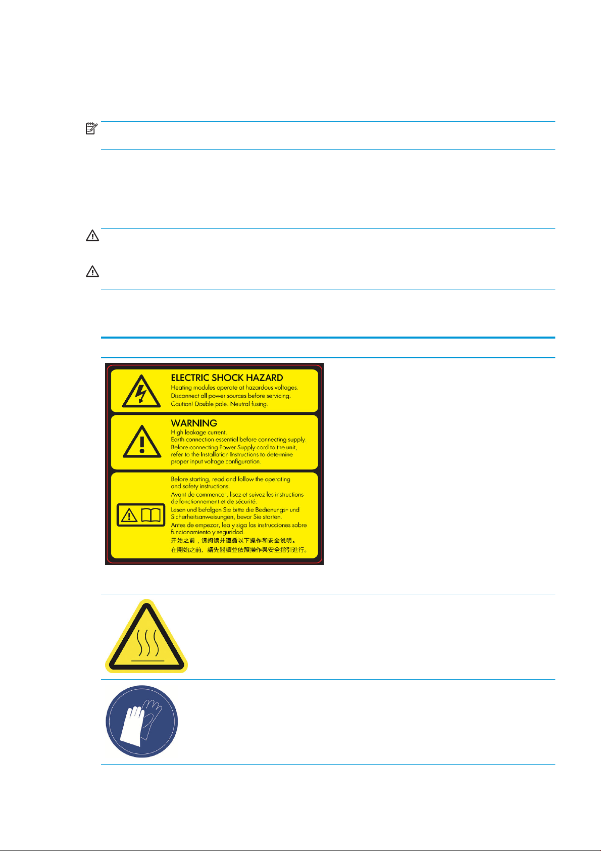
Label Explanation
For service personnel only
Electric shock hazard
Heating modules operate at hazardous voltage. Disconnect power
source before servicing.
CAUTION: Refer servicing to qualied service personnel.
In case of operation of the fuse, parts of the printer that remain
energized may represent a hazard during servicing. Before
servicing, turn o the printer using the Branch Circuit Breakers
located in the building's Power Distribution Unit (PDU).
WARNING! High leakage current. Current leakage may exceed 3.5
mA. Earth connection essential before connecting supply.
Equipment to be connected to earthed mains only.
See installation instructions before connecting to the supply. Ensure
that the input voltage is within the printer's rated voltage range.
Before starting
Read and follow the operating and safety instructions before
starting the printer.
Risk of burns. Let the printer cool down before accessing internal
parts.
HP recommends that you wear gloves when performing certain
maintenance and cleaning tasks. Wear heat-resistant gloves when
retrieving parts, either through manual extraction or after material
reclamation. The parts may be very hot.
ENWW Use of tools 11
Page 18
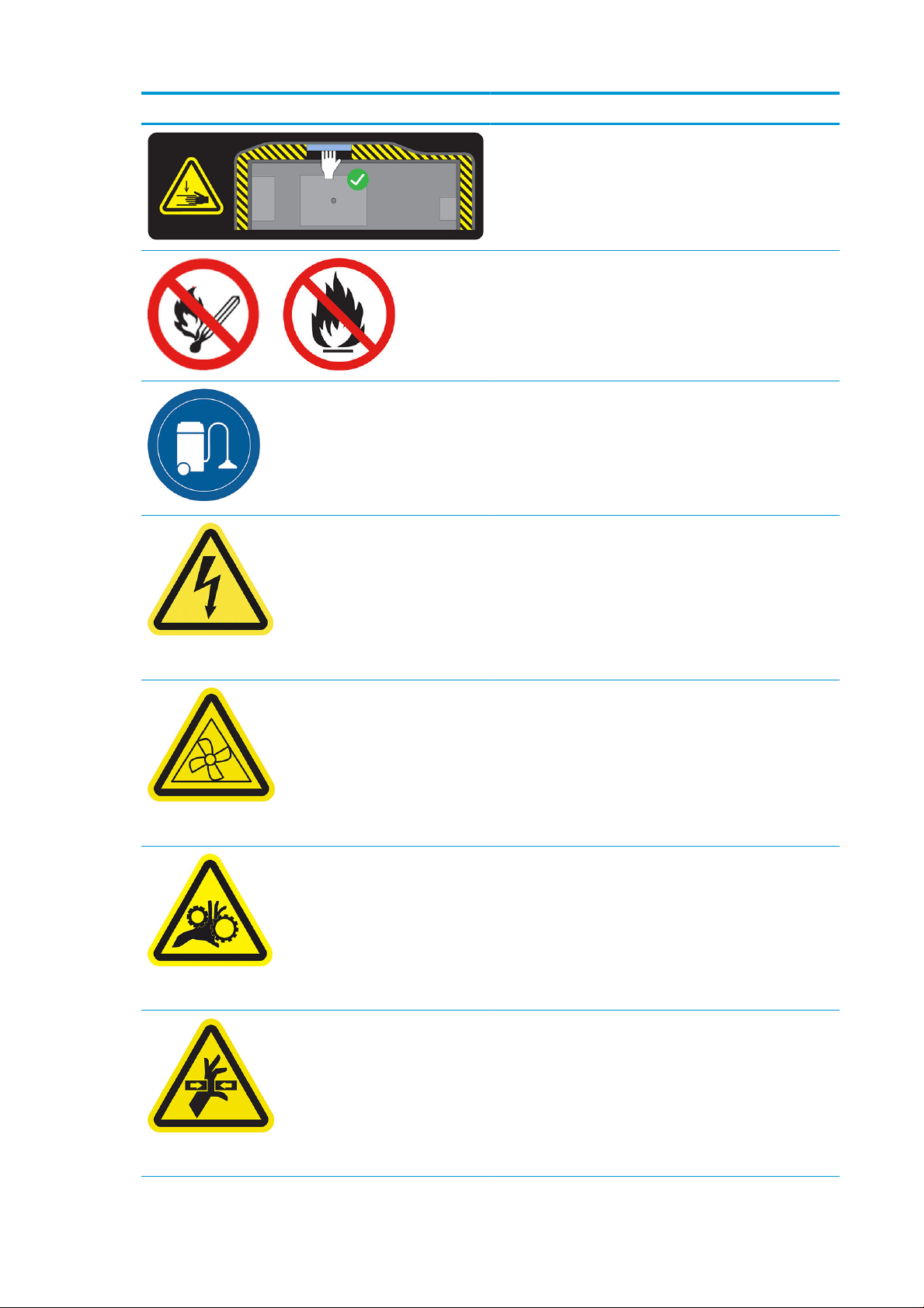
Label Explanation
Crush hazard. Keep your hands clear of the edge of the top cover.
Open and close the top cover using the handle (highlighted in blue)
only.
WARNING! Dust clouds can form explosive mixtures with air. Take
precautionary measures against static charges, and keep away
from sources of ignition.
No smoking, matches, or open ames close to printer or material
storage area.
An explosion-protected vacuum cleaner certied for collection of
combustible dust is required for cleaning.
Take measures to mitigate material spillage and avoid potential
ignition sources such as ESD (ElectroStatic Discharges), ames, and
sparks. Do not smoke nearby.
Disposal as per local laws.
Electric shock hazard. Disconnect power before servicing. Heating
modules and electrical cabinets operate at hazardous voltage.
For maintenance and service personnel only
For maintenance and service personnel only
For maintenance and service personnel only
Hazardous moving parts. Keep away from moving fan blades.
Risk of trapped ngers. Do not touch gears while moving: your
hands may be trapped between the gearwheels.
Hazardous moving parts. Keep away from the moving printhead,
lamp, and heater carriages. When printing, the print carriage travels
back and forth.
For service personnel only
12 Chapter 2 Safety precautions ENWW
Page 19
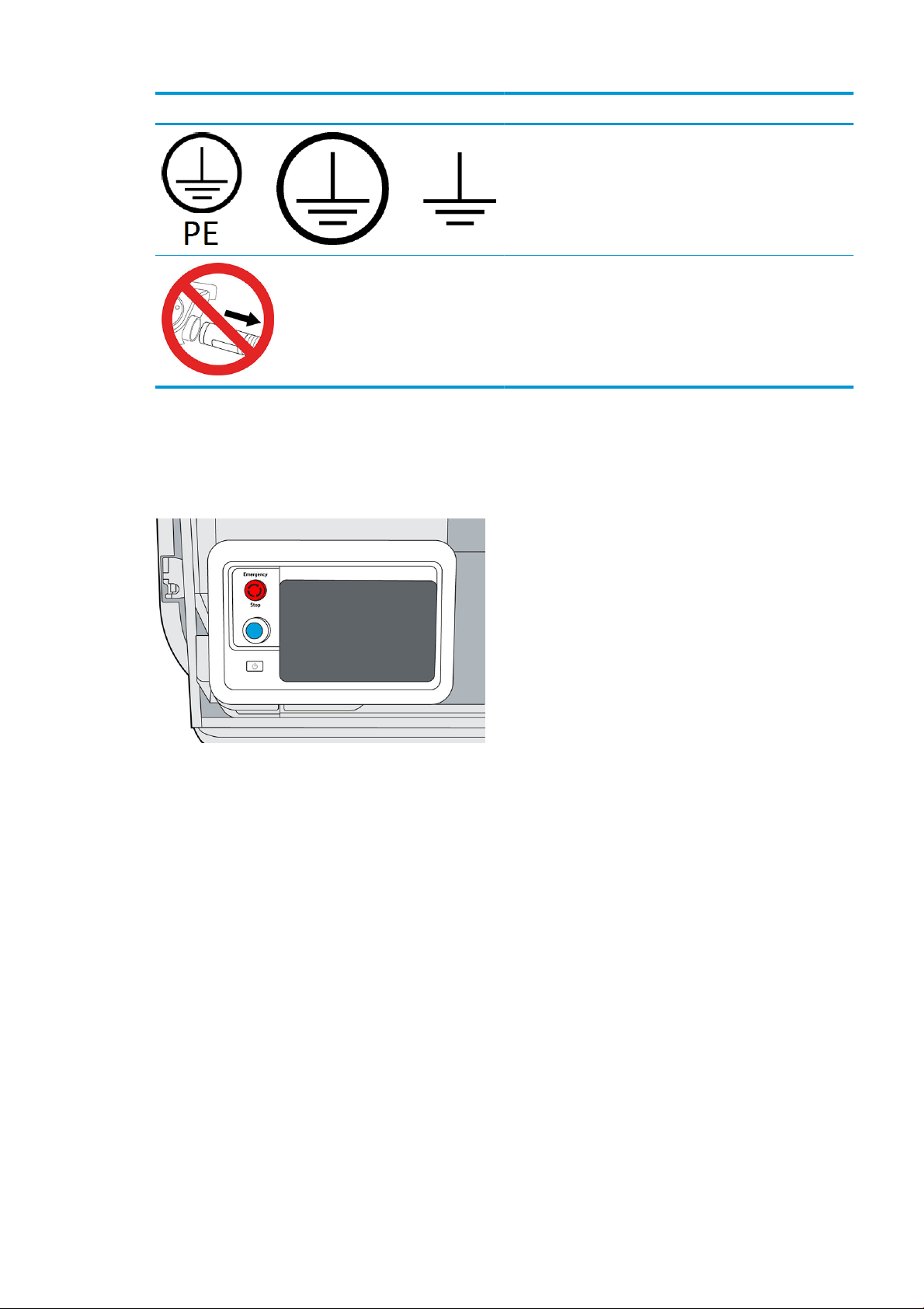
Label Explanation
Emergency stop button
There is a red emergency stop button on top of the printer, beside the front panel. If an emergency occurs,
simply push the emergency stop button to stop all processes.
Identies the Protective Earth (PE) terminal for qualied electricians,
and bonding terminals for maintenance/service personnel only. An
earth connection is essential before connecting to the supply.
Do not disconnect the hoses during the purging process.
The printer carriages, the fans, and the lamp module are halted; the top cover is locked until the internal
temperature decreases. A system error message is displayed.
Ensure that the emergency stop button is released before restarting the printer.
For safety reasons, access to the print zone is not permitted while printing is in progress. Let the printer cool
down before touching anything inside it.
To stop the printer completely, turn it o.
ENWW Emergency stop button 13
Page 20

3 Main components
●
Printer
●
Front panel
●
Set the administrator password
●
Software
14 Chapter 3 Main components ENWW
Page 21
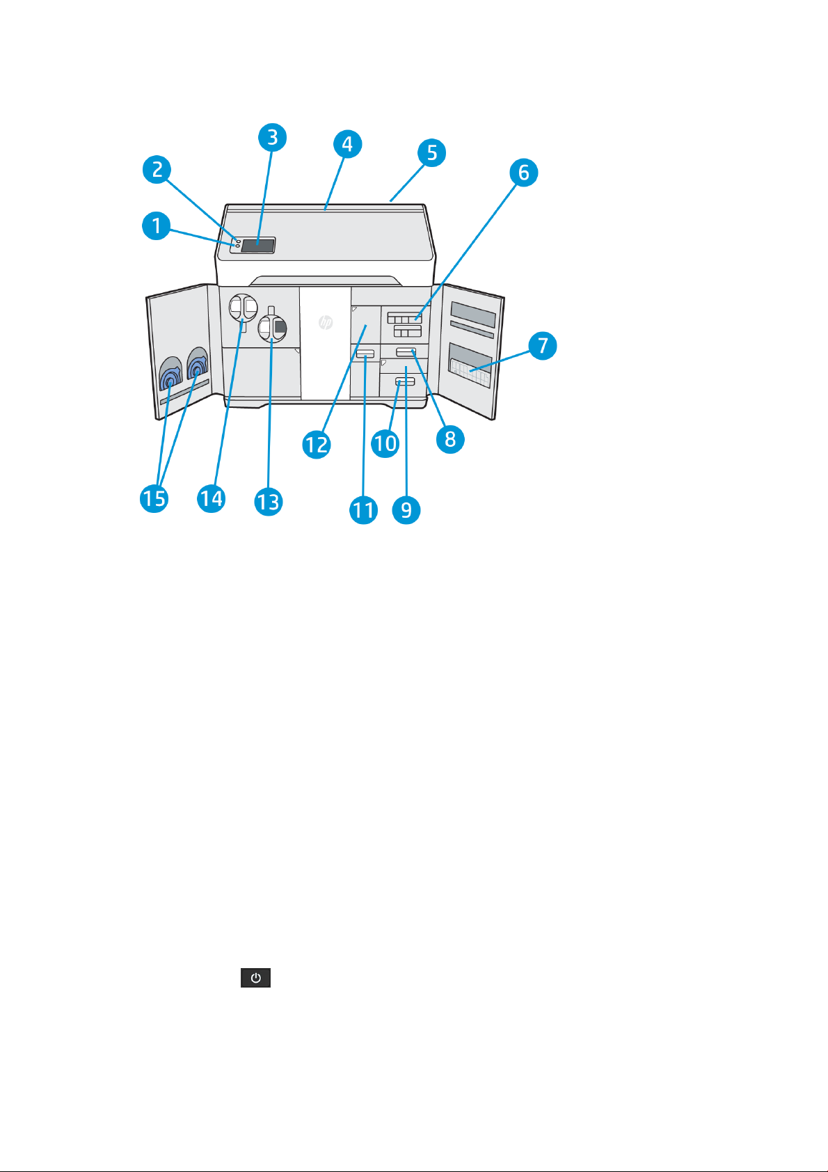
Printer
1. Rearm button
2. Emergency stop button
3. Front panel
4. Status beacon (500 series only)
5. Air intake lter (behind the printer)
6. Agent cartridges
7. Alignment plate
8. Distilled water tank (B3)
9. Scanner (B4)
10. Air exhaust compartment and lter (B5)
11. Material reclamation sieve (B2)
12. Material reclamation lter (B1), and access to the reclamation intermediate tank
13. Reusable material cartridge
14. Fresh material cartridge
15. Cartridge caps
The power button is beside the front panel, just below the rearm button.
ENWW Printer 15
Page 22
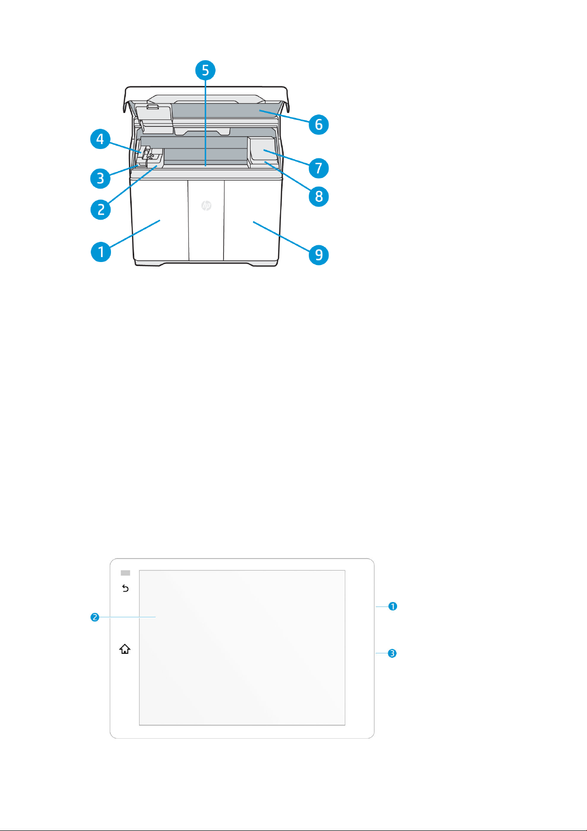
1. Material door
2. Fusing lamp
3. Recoating roller and cover
4. Fusing carriage (C1)
5. Build platform and build chamber
6. Top cover and viewing window (500 series only)
7. Print carriage (C2)
8. Printhead cleaning roll (under the print carriage)
9. Agent door
Front panel
The front panel is a touch-sensitive screen situated on the front left of the printer.
The front panel gives you complete control of your printer: from the front panel, you can view information about
the device, change device settings, monitor device status, and perform tasks such as supplies replacement and
printhead alignment. The front panel displays alerts (warning and error messages) when necessary.
16 Chapter 3 Main components ENWW
Page 23
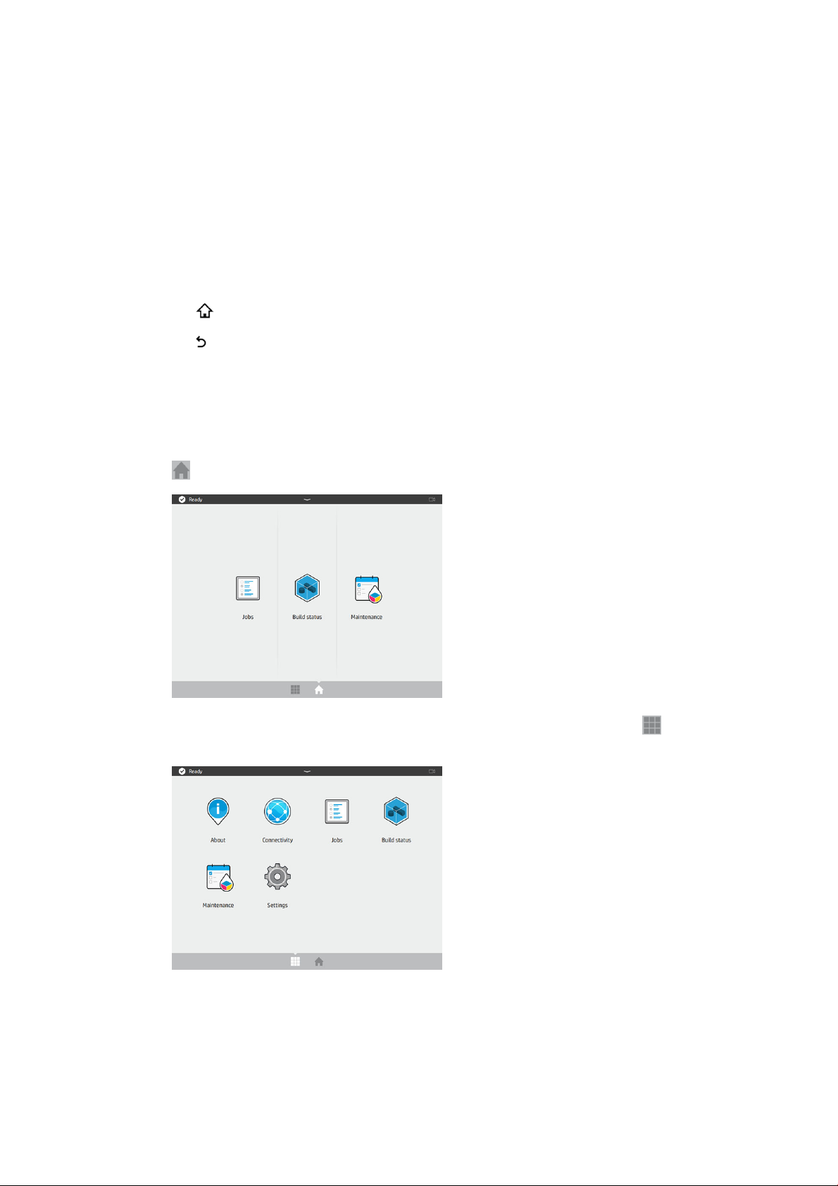
It includes the following components:
1. A Hi-Speed USB 2.0 host port, intended for connecting a USB ash drive, which can provide rmware
2. The front panel itself: an 8 inch, full-color, touch-sensitive screen with a graphical user interface
3. The loudspeaker
The front panel has a large central area to display dynamic information and icons. On the left side you can see
one or two xed icons.
Left xed icons
● Tap to return to the home screen.
● Tap to go back to the previous screen. This does not discard any changes made in the current screen.
Home screens
There are two top-level screens that you can move between by swiping your nger across the screen, or tapping
the appropriate icon at the bottom of the screen:
● The rst main screen provides direct access to the most important functions. It can be displayed by tapping
update les to the printer; it is located behind the front panel, accessible when the front panel is tilted up.
at the bottom of the screen.
● The all-app screen displays a list of all available apps. It can be displayed by tapping at the bottom of
the screen.
Status center
At the top of the front panel is the status center, which can be expanded by swiping down from the top. This is
visible on almost all screens, except when an action is taking place. In the status center, you can see the status of
the printer, and access various controls and alerts.
ENWW Front panel 17
Page 24
Status beacon (500 series only)
The printer has a beacon strip across the top cover; it gives a summary of the printer and job status, which can be
seen from a distance.
IMPORTANT: The information provided in the beacon is for functional information purposes only, and is not
relevant to your safety. Warning labels on the printer should always be heeded, regardless of the status indicated
by the beacon lights.
Beacon o The printer is ready for the next job.
White moving light The printer is in the middle of a process.
White light The printer has completed a process and is waiting for you.
Blue moving light The printer is printing a job.
Blue light A job is complete and the parts are ready to be retrieved.
Red light The printer is unable to print because of a system error; a job may have been canceled.
Change system options
You can change various printer system options from the front panel. Tap , then System.
● Language to change the language in which the printer operates.
● Select altitude to tell the printer its height above sea level.
● Display brightness to change the brightness of the front-panel display. The default brightness is 50.
● Speaker volume to change the volume of the printer's loudspeaker. Select O, Low, or High.
● Time zone to view or set the printer's time zone.
● Printer logs to request detailed troubleshooting information about system errors, system warnings,
printheads, or agents.
● Restore factory settings to restore the printer settings to their original values as set in the factory. This
option restores all of the printer settings except the Gigabit Ethernet settings and paper presets.
● Unit selection to select between imperial and metric measurements for your printer.
18 Chapter 3 Main components ENWW
Page 25
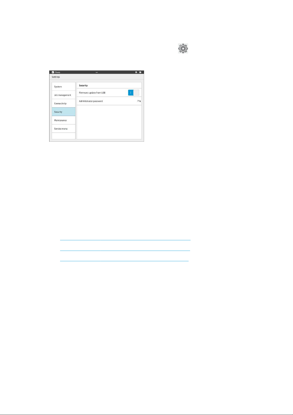
Set the administrator password
You can set the administrator password from the front panel. Tap , then Security > Manage password, and
enter the password. If a password has already been set, you will need to give the old password in order to set a
new one.
The administrator password must be given in order to change printer settings.
Software
HP SmartStream 3D Command Center
HP Smartstream 3D Command Center is a client application that fully monitors your HP 3D printers, and all other
complementary devices such as processing stations and build units, to fully utilize the power of the HP 3D
ecosystem. Command Center must be installed with your 3D devices. It helps you to make all of your 3D printing
builds successful: review print jobs and be ahead of the printer’s needs by remotely viewing rmware updates,
warnings, and errors.
HP Smartstream 3D Command Center software, manuals, and support for your 3D printing solution can be
downloaded from:
● http://www.hp.com/go/SmartStream3DCommandCenter/software
● http://www.hp.com/go/SmartStream3DCommandCenter/manuals
● http://www.hp.com/go/SmartStream3DCommandCenter/support
For more information about the Command Center, see the HP SmartStream 3D Command Center User Guide.
HP SmartStream 3D Build Manager
Use the powerful 3D print-preparation capabilities of HP SmartStream 3D Build Manager to help make all of your
3D printing jobs successful:
1. Add parts to begin preparing the print job.
2. Rotate, size, and position the part on the build platform.
3. Add, change, or remove part color.
4. Automatically locate and x 3D geometry errors.
5. Send a printer-ready le to a connected 3D printer or save the printable le.
ENWW Set the administrator password 19
Page 26

HP Smartstream 3D Build Manager software, manuals, and support for your 3D printing solution can be
downloaded from:
● http://www.hp.com/go/SmartStream3DBuildManager/software
● http://www.hp.com/go/SmartStream3DBuildManager/manuals
● http://www.hp.com/go/SmartStream3DBuildManager/support
For more information about the Build Manager, see the HP SmartStream 3D Build Manager User Guide.
20 Chapter 3 Main components ENWW
Page 27
4 Power on and o
NOTICE: Operate the printer only within the specied ranges of operating temperature and humidity (see the
site preparation guide). If the printer or supplies are exposed to conditions outside the environmental operating
range, wait at least 12 hours for everything to reach environmental operating conditions before turning on the
printer or using the supplies.
●
Turn the printer on and o
●
Main power switch
●
Away mode
Turn the printer on and o
Turn on the printer for the rst time
1. Ensure that the printer’s doors are all closed.
2. Turn the main switch at the rear of the printer to the on position.
3. Wait for the front panel to tell you that the printer is waiting for rearm.
4. Perform a visual check of the printer.
ENWW Turn the printer on and o 21
Page 28

5. When requested, press the blue rearm button beside the front panel, at the front left of the printer. This
enables all of the printer's high-power subsystems.
6. Wait for the front panel to indicate that the printer is ready. This can take several minutes. When
initialization is complete, the front panel displays a ready message. If a system error message is displayed,
see System errors on page 118.
Turn the printer on and o
Use the button beside the front panel to turn the printer on and o.
To turn o the printer for an extended period of time, rst turn it o with the button; wait for it to shut
down completely; then turn o the main switch at the rear of the printer.
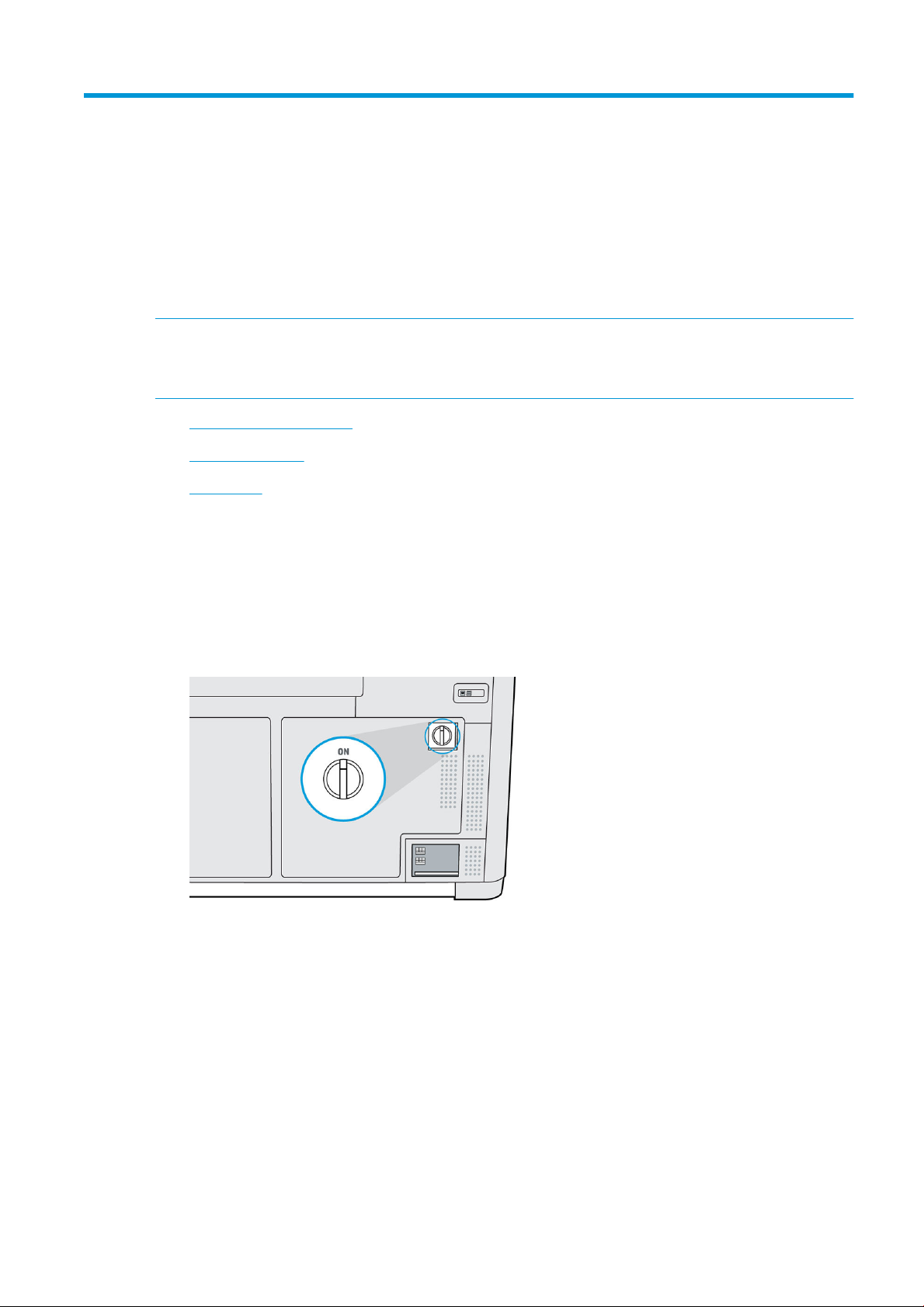
Main power switch
Leave the main power switch on at all times, unless you intend to move the printer.
If you plan to leave the printer unattended for more than a week, set it to away mode.
22 Chapter 4 Power on and o ENWW
Page 29

Away mode
If you plan to leave the printer unattended for more than a week, select Away mode from the maintenance
menu. The printer will perform a series of minor maintenance tasks in order to maintain the health of your
printheads.
Entering away mode is preferable to shutting the printer down completely. It will minimize the frequency of
printhead replacement, as well as help maintain steady operating procedures with predictable costs based on
usage. The printer will remain locked throughout away mode; it can be returned to normal operation from the
front panel.
CAUTION: If you turn o the printer for an extended amount of time, it cannot maintain printhead nozzle
health, and you may nd that you need to replace the printheads when you eventually turn it back on.
ENWW Away mode 23
Page 30

5 Printer networking
Introduction
The printer provides a single RJ-45 port for a network connection. For optimal performance, HP recommends
using Cat 5/5e or Cat 6 cabling and gigabit-capable local network equipment.
A correct network setup is required to operate the printer, as all communication with printing and management
software goes through the network.
IMPORTANT: In order to print, the printer must be connected to the Command Center, and the Command Center
must be connected to the cloud.
Connectivity requirement and remote monitoring
The customer will allow HP to install the HP Command Center software (or other applicable HP software that
controls the HP product and enables remote monitoring) on the customer’s computer.
The customer will keep that computer connected to the HP product, and the customer will keep the
HP Command Center software running on that computer and connected to the HP product at all times.
The customer will provide, at the customer’s sole expense, permanent HP Command Center software
connectivity to the HP secure cloud via permanent Internet connection through an HP-approved communications
channel and ensure such connectivity at all times as further specied in the site preparation guide. The customer
is responsible for restoring connectivity in a timely manner in the event of interruptions.
THE CUSTOMER AGREES THAT FAILURE TO MAINTAIN THE PRODUCT’S CONNECTION TO THE HP CLOUD AS
SPECIFIED IN THE SITE PREPARATION GUIDE WILL RESULT IN LIMITED OR NO PRODUCT FUNCTIONALITY AND
LIMITED SERVICE LEVEL.
HP products may collect the customer machine data. The customer grants HP and/or an HP authorized agent
permission to access remotely, via the HP Command Center software, the customer machine data from
HP products.
The customer machine data will be used by HP and/or an HP authorized agent for the purpose of providing
remote support, enabling enhanced diagnostics, preventive maintenance, software updating, calculating
supplies and consumables usage and statistics, and evaluating improvements to HP’s products and oerings in
the future. In addition, the customer machine data will help HP to determine how HP products are being used,
which product features are used the most, and to calculate various aggregate HP product usage statistics.
HP and/or HP authorized agents respect your privacy, are committed to protecting your machine data, and will
take reasonable precautions to prevent unauthorized access or disclosure and ensure the appropriate use of
your machine data. In the event that some data may be categorized as individual level data, HP and/or an
HP authorized agents will maintain the privacy of any such data, as well as all data collected, in accordance with
the HP Privacy Statement (http://www.hp.com/go/privacy) and the Personal Data Rights Notice
(http://welcome.hp.com/country/privacy/privacynotice) where applicable.
"Customer machine data" means data from the customer’s HP product that may include but is not limited to the
following: HP product usage data; HP product production data; HP product system events; HP product
24 Chapter 5 Printer networking ENWW
Page 31

maintenance and calibration history; HP product model number; HP product serial number; HP product rmware
version; HP product IP address; consumable status and history; sensor activity; quantity and type of printheads
used; build ID; build duration; and/or print mode. Customer machine data does not include: design les, parts
les, job names, job contents, part geometries, thermal maps, user names, or part names.
Conguration
To access the network settings, tap and then on the front panel.
Hostname
You can assign a customized hostname to the printer. If the network infrastructure supports it, the printer will
attempt to register the hostname to the DNS service, making it possible to address the printer using the
hostname rather than the IP address.
Similarly, you can assign the domain suix, to dene the printer’s fully qualied domain name.
IPv4 conguration
You can select whether the printer should try to discover automatically the IPv4 network settings using the DHCP
protocol, or whether you want to congure them manually. These settings include:
● IP address: The unique Internet Protocol address assigned to the printer.
● Subnet mask: The mask corresponding to the printer’s IP address.
● Default gateway: The IP address of the network gateway.
● DNS conguration method: Whether DNS servers should be assigned by DHCP service or manually.
● Primary and secondary DNS servers: The IP addresses of the DNS servers.
Link speed
The embedded network controller supports connection to IEEE 802.3 10Base-T Ethernet, IEEE 802.3u 100BaseTX Fast Ethernet, and 802.3ab 1000Base-T Gigabit Ethernet compliant networks. When connected and powered
on, the printer auto-negotiates with your network to operate with a link speed of 10, 100, or 1000 Mbps, and to
communicate using full- or half-duplex mode. However, you can manually congure the link using the printer's
front panel, or through other conguration tools once network communication is established.
ENWW Conguration 25
Page 32

6 Design and printing guidelines
●
Introduction
●
File preparation
–
File usage in the end-to-end workow
–
Minimum specication for parts
–
Coloring parts
–
Saving and exporting les
–
Recommended le export formats for color models
–
Tesselation problems
–
Repairing les
–
HP SmartStream 3D Build Manager
26 Chapter 6 Design and printing guidelines ENWW
Page 33

Introduction
3D printing oers a much higher level of freedom in terms of design than any other traditional manufacturing
technology. Designers and engineers can benet from this, and use new geometries and concepts that were not
feasible before. However, in order to optimize the design to be printed with MJF, you should be aware of some
characteristics of the printing process and its capabilities, as this could help to get the best of the technology.
The design and printing guidelines oer an overview of the steps to follow before sending a job to print, from le
preparation to the considerations that should be taken into account in the design of the parts and the orientation
of them in the build chamber to optimize the nal part quality and printing performance.
File preparation
File usage in the end-to-end workow
In the end-to-end workow of the printing process, the les pass through dierent software applications. For
example, the rst design may be done in a CAD program, while the job preparation will be handled in
HP SmartStream 3D Build Manager. If required, the printed part can be scanned in 3D and compared with the
original design.
Minimum specication for parts
When designing parts in your 3D modeling software, HP recommends keeping this minimum specication in
mind to avoid issues with parts and to achieve the best quality.
The minimum printable features in planes X, Y, and Z are as follows:
Minimum hole diameter at 1 mm thickness 0.5 mm (0.02 in)
Minimum shaft diameter at 10 mm height 1 mm (0.04 in)
Minimum printable font size for embossed or debossed letters or numbers 6 pt (2.1 mm) (0.083 in)
Minimum clearance at 1 mm thickness 0.5 mm (0.02 in)
Minimum slit between walls 0.5 mm (0.02 in)
ENWW Introduction 27
Page 34

● Engraving. Multi Jet Fusion technology allows you to print letters and drawings with a very high resolution
and denition.
For the best possible output, any text, number, or drawing included in a part of the same color should have
at least 1 mm of depth or height. When using contrasting colors, there is no minimum.
The best orientation for embossing and debossing letters is to place them upside down in the build
chamber.
28 Chapter 6 Design and printing guidelines ENWW
Page 35

● Solid part or structural ll. Multi Jet Fusion allows you to print topology-optimized, generative designs or
even small lattice structures. This kind of design helps to reduce the weight of the part and the quantity of
material used, which not only reduces the cost of the part but also helps to reduce the operating cost in
applications that are very weight-sensitive.
The minimum gap recommended in a lattice structure to ensure that all the material inside the part can be
removed is 5 mm.
● When printing a cantilever, the minimum wall thickness depends on the aspect ratio, which is the length
divided by the width.
Aspect ratio = Length/Width
For a cantilever with a width less than 1 mm, the aspect ratio should be less than 1. There are no specic
recommendations for widths greater than 1 mm.
ENWW File preparation 29
Page 36

● In general, the minimum recommended wall thickness is 0.5 mm for short walls oriented in the XY plane,
and 1 mm for short walls oriented in the Z plane.
For parts with a high aspect ratio (>10:1), HP recommends increasing the wall thickness, or adding ribs or
llets to reinforce the part.
Very thick walls can accumulate heat and cause spot shrinkage in dense areas with an accumulation of
material.
For best results, ribs should be no thicker than their base wall.
TIP: Hollow out the part as much as possible, saving agent and material, and reducing sink marks.
● Minimum gap between parts to be assembled after printing. Sometimes a pair of printed parts need to t
together for the nal application. In these cases, HP recommends gaps of at least 0.5 mm between the
interface areas that should t together, in order to ensure correct assembly.
30 Chapter 6 Design and printing guidelines ENWW
Page 37

● Minimum spacing and clearance between parts printed as assemblies. Assembly parts that are printed
together should have a minimum clearance of 0.7 mm. Parts with thick walls should have a larger gap to
ensure suicient material escape paths.
● Hollow closed geometries. Multi Jet Fusion is a process in which the parts are built by selectively fusing the
desired areas of a material-based layer. If the parts printed are hollow, drain holes need to be added to the
design to remove the material. The minimum recommended diameter of the holes is 5 mm; preferably
larger, for ease of cleaning. HP recommends including at least two holes.
● Glue lines. Parts larger than the maximum build size can be printed with Multi Jet Fusion by splitting them
into dierent parts. They can then be joined together by glueing, welding, or by pin inserts.
If you plan to glue parts together, HP recommends including interlocking features such as those shown in
the pictures below: as a guide to position the parts, to help them to bond together, and to facilitate the
glueing process. Remember to leave an additional space of 0.2 mm between parts for the glue, in addition
to the minimum spacing between parts printed as assemblies (see above).
ENWW File preparation 31
Page 38

● Ducts. To remove material from narrow ducts, consider designing and printing a strip or a chain through the
duct. When the parts have been printed, you can pull out the chain to dislodge most of the material. Any
remaining material can be removed by the normal cleaning process.
Coloring parts
After creating your 3D model, it is recommended to color your model before bringing it into the HP SmartStream
3D Build Manager since coloring options are limited there. There are two primary ways of adding color to 3D
models:
● Color addition by part, face, or shell: Commonly seen in CAD programs, this allows you to color specic
areas of a part.
A model with the entire part colored
A model with the dierent colors on dierent faces
32 Chapter 6 Design and printing guidelines ENWW
Page 39

● Texture mapping: Commonly seen in graphic art programs, texture mapping takes an image and wraps it
around a 3D object.
A model with a texture map
See your CAD or graphic arts software guidelines for how to use these features. You can also color previously
uncolored models in a free program, such as Microsoft 3D Builder, which is free on all Windows systems. 3D
Builder has easy-to-use color and texture map additions for beginners.
Saving and exporting les
After your les are designed and colored, your model needs to be tessellated, or converted into triangles, which
are used by the printer to create layers. Tessellation occurs when you save or export your model le into specic
le formats. The HP SmartStream 3D Build Manager accepts four dierent le formats:
● 3MF
NOTE: 3MF is the preferred le format for HP SmartStream 3D Build Manager.
However, defer to the recommended le export format chart below for color models.
● VRML 2 (.wrl)
● OBJ
● STL
NOTE: STL les do not carry color information. Use 3MF, VRML 2, or OBJ le formats for color models.
When saving or exporting your le, note that a normal le size for a model is about 1–200 MB, but the size
depends on the type of software that created it, the number of triangles, the number and level of details, and so
on. HP does not recommend working with les of more than 4 GB—beyond that size, the extra resolution in the
le may have no eect on the printed part.
When exporting to STL, OBJ, or VRML 2 from a CAD package, you are often required to introduce some
parameters such as angle tolerance and deviation chord height. These parameters dene the resolution and le
size of the part. The recommended parameters when exporting parts are an angle tolerance in the range 1–5
and a deviation chord height in the range 0.05–0.2. The angle tolerance should be reduced for parts with
cylindrical or spherical shapes, and the chord height should be minimized for parts with ne details and small
features.
Below, you will nd some recommended export parameters/settings for common 3D modeling programs.
Siemens NX recommended export settings
Recommended export format: VRML (.wrl)
ENWW File preparation 33
Page 40

SolidWorks recommended export settings
Recommended export format: 3MF (.3mf)
Solid Edge recommended export settings
Recommended export format: 3MF (.3mf)
34 Chapter 6 Design and printing guidelines ENWW
Page 41

Creo Elements recommended export settings
Recommended export format: VRML (.wrl)
Recommended le export formats for color models
In addition to having the correct export settings, HP recommends saving your color models in specic le
formats, depending on which 3D modeling software program you use. Note that not all programs can export
texture maps, even though texture mapping features may be available in the software. If this is the case, it is
recommended to bring your uncolored model into a software that can export texture maps, and then add the
texture map in that software. There are free software options, such as Microsoft 3D Builder and Blender, that
allow you to do this.
Software Recommended le export format Can export texture?
3D Builder (16.1.651.0) 3MF Yes
Adobe Photoshop (19.1.4) VRML or OBJ Yes
Autodesk 3ds Max (2019) VRML Yes
Autodesk Fusion 360 (2019) STEP No
Autodesk Inventor (2019) OBJ No
Autodesk Maya (2019) OBJ Yes
Autodesk Netfabb (2019.2) 3MF Yes
Blender (2.79) OBJ Yes
Dassault CATIA (5) VRML Yes
Dassault SOLIDWORKS (2019) 3MF Yes
Materialise Magics (21.0) 3MF Yes
PTC Creo Elements (19) VRML No
PTC Creo Parametric (3.0) OBJ No
Rhino (6) VRML Yes
Siemens NX (12.0) VRML No
Siemens Solid Edge (ST10) 3MF No
NOTE: If you are saving your color models in the recommended format and are still experiencing issues
correctly opening your color models in HP SmartStream 3D Build Manager, see the printing tips and tricks
document.
ENWW File preparation 35
Page 42

Tesselation problems
These are some common problems that you could experience during tessellation/exporting your les:
● Too many or too few triangles
Too many triangles are diicult to process and, when a certain size is reached, the extra triangles do not
provide any further accuracy. For this reason, an excess of triangles could increase processing time for no
benet.
Triangulation of a surface causes faceting of the 3D model. The parameters used to output an STL model
aect how much faceting occurs.
Example of tessellation
● Holes in triangles
STL models commonly suer from surfaces that are not joined to their neighbors, and missing surfaces.
Repairing les
File-repairing software
● Magics – Materialise
● Autodesk Netfabb
● HP SmartStream 3D Build Manager
Common errors
Some common errors that cause part-quality-related issues are illustrated below. They can be xed in the native
CAD software; or, if that is not available, in Magics, Netfabb, or HP Smartstream 3D Build Manager. If these les
are not xed before attempting to build the design, either the software will not allow you to proceed due to poor
le quality, or your part will not have good quality. Therefore, it is prudent to spend time at this stage to check
that the CAD le designer produced a high-quality and printable design.
● Triangles not joined
36 Chapter 6 Design and printing guidelines ENWW
Page 43

● Overlapping triangles
● Holes in parts
● Flipped-direction triangles
● Tiny shells
ENWW File preparation 37
Page 44

HP SmartStream 3D Build Manager
The HP SmartStream 3D Build Manager must be used to send jobs to print. Therefore, after les are exported,
either from your CAD, graphic arts, or separate 3D build manager software, they must be brought into
SmartStream 3D Build Manager.
NOTE: For optimal dimensional accuracy, export parts separately instead of grouping them within one le.
In HP SmartStream 3D Build Manager, you will be able to access some color editing features, including:
● The ability to color an entire part with one color of your choosing
● The ability to edit the hue, lightness, and saturation of existing colors
● The ability to display a print preview of the color part to be printed
● The ability to print a color set model to test colors
See the HP SmartStream 3D Build Manager User Guide (http://www.hp.com/go/SmartStream3DBuildManager/
manuals) for full descriptions of these features, or view this video: https://www.youtube.com/watch?
v=3IfrpLMrJ4U&t=14s.
The software preparation process may take from 15 minutes to 2 hours depending on the complexity of the job.
It can be done while printing other jobs. Once ready, you can select the job to be printed from the job queue on
the printer’s front panel. If an error occurs while processing, a message appears on the front panel, and the
printer cancels the job. To retry, you have to resubmit the job.
38 Chapter 6 Design and printing guidelines ENWW
Page 45

7 Send a job
Use appropriate software to send the job to the printer, such as the HP SmartStream 3D Build Manager (see the
HP SmartStream 3D Build Manager User Guide).
Before printing any job, the printer performs various checks. See Job preparation list on page 42.
ENWW 39
Page 46

8 Select a job
Job list app
The job list app in the printer’s front panel displays the status of all jobs. Possible statuses are:
● Waiting to process: The job has been received by the printer and is queued for processing.
● Processing: The job is being analyzed by the printer.
● Processed: The job is ready to be sent for printing. Either it has never been printed, or it is ready for
reprinting.
● Ready to print: The job is ready to be printed. When this job is selected, the Print button is available.
● Sent to print: The job has started printing.
Select a job to be printed
1. Tap Jobs on the home screen.
2. Select the processed job and tap Print.
3. The printer checks that all subsystems and supplies are ready to complete the build (see Job preparation
list on page 42). If your attention is needed, the printer noties and advises you: a list appears with all of
the required and recommended tasks to ready your printer. To print the job, address any issues on the list
by following the front-panel instructions. Once you have completed all the tasks on the list, the printer will
run a second check to ensure it is ready to print the job. If there are any additional issues, the front panel
will again provide instructions.
4. The printer starts the printing process. Wait until the printer tells you that the process is complete.
40 Chapter 8 Select a job ENWW
Page 47

9 Printer preparation
●
Job preparation list
●
Agents
●
Material
–
Mix ratio
–
Material cartridges
○
Replace a material cartridge
○
Maintain the cartridges
○
Store the cartridges
●
Distilled or deionized water
●
How to recycle consumables and printed parts
ENWW 41
Page 48

Job preparation list
Before printing, the printer performs some checks to ensure that it is ready to print the whole build. These
include the following checks:
● Printer clean (see Clean the print area on page 71)
● Job compatible with device
● Printhead ready (see Align the printheads on page 109)
●
Cloud connected (see Printer networking on page 24)
● Enough agent (see Agents on page 42)
● Enough material (see Material on page 45)
● Enough water in the distilled water tank (see Distilled or deionized water on page 48)
● Printhead cleaning roll ready (see Replace the cleaning roll on page 87)
● Filters ready (see Maintenance on page 65)
● Lamp clean
● Doors closed
If the printer nds any problem, it may ask you to contact your support representative for assistance.
Agents
Please note:
Status
The printer uses seven types of agents: black, detailing, fusing, yellow, magenta, cyan, and bright fusing agents.
● This is a dynamic security-enabled printer. Cartridges using a non-HP chip will not work. For more
information, see http://www.hp.com/go/learnaboutsupplies.
● This printer is not designed to use continuous agent systems. To print successfully, remove any continuous
agent system and install genuine HP cartridges.
● This printer is designed for agent cartridges to be used until they are empty. Relling cartridges prior to
depletion could cause your printer to fail. If this happens, insert a new cartridge to continue printing.
At the printer’s front panel, tap , then Agents, then tap any agent to see its status:
● Check pending: The cartridge is present, but has not yet been checked. The agent door must be closed
before the cartridge can be checked.
● Checking: The cartridge is being checked.
● Not present: The cartridge is not present (this is not an error status).
● Missing cartridge: The cartridge is not present while you are trying to perform an action or workow that
requires a cartridge, such as a build (this is an error status).
● Out of agent: The agent should be replaced.
● Incompatible cartridge: The cartridge is incompatible with the slot it was inserted into (for example, yellow
cartridge in black slot).
42 Chapter 9 Printer preparation ENWW
Page 49

● Incompatible cartridge region: Cartridges work only in specic regions of the world, for world trade and
● Reseat required: The agent is not seated properly; try removing and reinserting it.
● Replacement required: The agent is faulty and should be replaced.
● Very low agent: The agent intermediate tank is very low and the cartridge is empty.
● Low agent: The agent intermediate tank is low and the cartridge is empty.
● Expired agent: The agent has reached its expiration date. Using expired agents may aect the warranty on
● Ready: The cartridge is ready.
● Altered cartridge: The cartridge is unknown or altered.
● Non-HP agent detected: The cartridge contains non-HP agent.
NOTE: The level of each agent shown on the front panel is an estimate.
LEDs
● White: If the light is on, the cartridge is empty and needs to be replaced.
Replace an agent
regulation reasons. This status appears if the agent and the printer are registered for dierent regions.
your printheads.
NOTE: Printer processes may be stopped while any doors are open.
NOTE: If you remove a cartridge from the printer for any reason, try to replace it again as soon as possible. Do
not open or unpackage cartridges until you are ready to install them.
At the printer’s front panel, tap , then Agents > Replace.
1.
2. Open the agent door.
3. Locate the agent to be replaced. You can see which agent needs to be replaced on the front panel; it is also
indicated by a white LED above the cartridge.
NOTE: More than one cartridge can be replaced at a time.
4. Press the agent to release and remove it; you should hear a click as you remove it.
ENWW Agents 43
Page 50

5. Old agent cartridges can be recycled through HP's Planet Partners Program, where available. Visit
http://www.hp.com/recycle/ for more information. Where the program is not available, dispose of the
cartridges according to local regulations.
6. Follow the instructions on the new agent cartridge to prepare it for installation.
CAUTION: Do not touch the metal contacts on the cartridge. Fingerprints on the contacts can cause
connection errors.
7. Insert the new agent cartridge until you hear a click.
8. Close the agent door.
9. Tap Finish and Check on the front panel.
TIP: If the new agent fails to work, see Agent troubleshooting on page 62.
44 Chapter 9 Printer preparation ENWW
Page 51

Material
The printer uses a mixture of fresh and reusable material—the conguration for PA12 material is 20% fresh,
80% reusable. The reusable material slot serves two functions:
● Adding reusable material. You may be prompted to put more reusable material into the machine if there is
● Removing excess reusable material. You may be prompted to remove reusable material if there is not
Material states
● Fresh: New, unused material.
● Reusable: Material that the printer has reclaimed from previous jobs, which may be reused for future jobs.
● Waste material: Used material that will not be reused.
● Mix ratio: A mixture of fresh and reclaimed material.
● Empty: Empty cartridges should be stored and used to reclaim material.
Mix ratio
not enough to maintain the mix ratio and meet the requirements of the job; the front panel will walk you
through installing a reusable material supply.
enough space to hold all reusable material that the job will generate; the front panel will walk you through
installing an empty or partial supply to accommodate the excess material.
The default mix ratio is 20% fresh and 80% reusable material. However, when submitting a job through HP
SmartStream 3D Build Manager, you can select your preferred mix ratio.
When a job is selected to print, the correct levels of both fresh and reusable material can be added through
guided workows on the front panel before the start of printing.
Some jobs can be printed successfully only by adjusting the mix ratio based on the printer capacity.
If the submitted job exceeds the capacity of the printer, return to the build submission software to reduce the
height of the build or the packing density.
Material cartridges
The material cartridges dispense the material in the printer. Each material cartridge has a capacity of 10 liters.
The printer will not accept cartridges that have been modied or tampered with. See the material list for ordering
information.
There are two material cartridge slots, one for fresh material (on the left) and the other for reusable material (on
the right).
Any time you remove an empty cartridge from the fresh slot, be sure to peel o the fresh material label to reveal
the reusable material label underneath. This cartridge can now be lled with reusable material and used in the
reusable material slot.
Both fresh and reusable cartridges must be installed in order to print.
NOTE: Waste material that has not been automatically reclaimed should not be reintroduced into the system: it
could cause print-quality issues.
ENWW Material 45
Page 52

You can store empty, partially full, or full reusable cartridges for later use.
Do not throw away the blue material cartridge cap. Storage for the caps is provided on the interior of the material
door. Any time you remove a material cartridge from the printer, be sure to put the cap back on.
Special care must be taken to avoid personal injury when handling heavy cartridges.
10 liter cartridges
Material Total cartridge weight Net weight of material
HP 3D HR CB PA 12 10L 5 kg (11 lb) 4 kg (8.8 lb)
Replace a material cartridge
A cartridge should be removed and replaced when indicated in the front panel, and by the waynding LED above
or below the cartridge.
CAUTION: Cartridge removal must be initiated from the front panel. The cartridges are physically latched to the
printer; do not try to pull them out without using the front panel.
CAUTION: A cartridge may be sensitive to temperature, humidity, or other factors. Using cartridges under
uncontrolled conditions can aect the functionality of the printer or severely damage it.
LEDs
● Waynding: The waynding LED is in the form of a vertical line; it is located below the fresh material slot
and above the reusable material slot. If the LED is on, the cartridge needs to be replaced.
● Lock icon: The lock icon LED is located beside the waynding LED for each material slot. If the LED is on, the
cartridge is locked in place. To remove a cartridge, you must rst unlock it, using the Supplies tab.
Cartridge replacement
1. At the front panel, tap , then Material > Fresh material or Reusable material > Replace.
46 Chapter 9 Printer preparation ENWW
Page 53

2. Open the material door. You will see a white LED in the form of a vertical line above or below the cartridge
that needs to be replaced.
3. Pull the handle straight out to remove the cartridge from the slot.
NOTE: Each cartridge weighs 1 kg (2.2 lb) empty and 5 kg (11 lb) full.
4. Reattach the cap before storing the cartridge.
5. Remove the cap from the packaging of the new cartridge.
6. If you are replacing a reusable material cartridge, wait (about 10 seconds) until the front panel tells you
that the printer is ready to receive the new cartridge.
ENWW Material 47
Page 54

7. Insert the new cartridge into the slot until the lock icon turns on. There is no need to rotate it: just push it
straight in.
8. Close the material door.
9. Tap Finish and check on the front panel.
Maintain the cartridges
Before use, the material must acclimatize to the environmental conditions of the room for at least two days.
During the normal lifetime of a cartridge, no specic maintenance is required. However, to maintain the highest
quality, replace a cartridge when it reaches its expiration date. An alert on the front panel noties you when any
cartridge reaches its expiration date.
Store the cartridges
Cartridges should be stored according to cartridge specications. Before use, a cartridge should be kept at the
printer’s environmental conditions for at least 2 days.
CAUTION: HP recommends storing only capped cartridges. Storing an opened cartridge containing material can
render the material unusable and cause safety hazards, such as a cloud of material if dropped. Depending on the
material, it can be sensitive to temperature, humidity, or other factors. Using cartridges under uncontrolled
conditions can aect the functionality of the printer or severely damage it. Placing the cap back on the cartridge
is necessary for storage to prevent material from spilling; if excess material is lost, the cartridge may not be
recognized by the printer because it is considered to have been tampered with.
Distilled or deionized water
Rell the water tank
Rell the water tank when prompted by the front panel. Printing cannot start until there is suicient water to
complete the job.
CAUTION: Never use tap water.
1. Open the agent door.
48 Chapter 9 Printer preparation ENWW
Page 55

2. Open the water tank drawer.
3. Open the tank cover.
4. Add distilled or deionized water to the tank until it reaches the full line.
5. Wipe up any excess water or splashes with a clean cloth or towel before closing the cover.
ENWW Distilled or deionized water 49
Page 56

6. Close the tank cover.
7. Close the water tank drawer.
8. Close the agent door to clear the low water message and continue printing.
How to recycle consumables and printed parts
NOTICE: Parts and waste generated during the printing process should be disposed of in compliance with
federal, state, and local regulations. Consult your local authorities to determine the correct manner in which to
dispose of waste. Also check with your local plastics recycler, as some printed parts may be appropriate for
municipal recycling streams. Where appropriate, HP recommends that the parts be marked with the applicable
plastic marking code according to ISO 11469 to encourage recycling.
HP provides many free and convenient ways to recycle your used HP hardware, cartridges, and other
consumables. For information about these HP programs, see http://www.hp.com/recycle/.
The following consumables for your printer can be recycled through HP’s Planet Partners Program, where
available:
● Agent cartridges
● Lamps
Empty material cartridges can be recycled through commonly available recycling programs.
Dispose of the following supplies in compliance with federal, state, and local regulations:
● Full or partially full material cartridges
● Printhead cleaning roll
50 Chapter 9 Printer preparation ENWW
Page 57

● Filters
● Printheads
HP recommends that you wear gloves while handling printer supplies.
ENWW How to recycle consumables and printed parts 51
Page 58

10 Print
●
Indemnity to HP for 3D parts printed by the printer
●
Cancel a job
●
Check status on the front panel
●
Check status remotely
●
Possible errors while printing
52 Chapter 10 Print ENWW
Page 59

Indemnity to HP for 3D parts printed by the printer
The customer assumes all risk relating to or arising from the 3D printed parts. HP shall have no responsibility for
any loss or damage caused by the 3D printed parts.
The customer shall defend, indemnify, and hold harmless HP from all third-party claims, losses, liabilities, costs,
damages, judgments, awards, expenses (including but not limited to attorney’s fees, expert witness fees, and
bonds) arising out of the customer’s or its customers and/or partners or end user’s use, operation, distribution,
sale, marketing, or possession of the 3D printed parts. HP shall provide prompt notication of the claim and
cooperation with the defense.
Notwithstanding anything to the contrary contained herein or otherwise communicated to the customer, the
customer is solely responsible for the evaluation of and determination of the suitability and compliance with
applicable regulations of the products and/or 3D printed parts for any use, especially for uses (including but not
limited to medical, dental, food contact, automotive, aerospace, heavy industry, and consumer products) that are
regulated by US, EU, and other applicable governments. "3D printed parts" means any output or parts created,
developed, and/or produced by the customer or its customers, partners, and/or other end-users from use of the
products.
Cancel a job
If you need to cancel the job while printing, tap Cancel print and conrm it in the build status app on the printer's
home screen. The printer will cancel the job after shutting down the current process.
Depending on the state the job is in when it is canceled, the printer may need to cool to a safe temperature
before unlocking the top lid and allowing access to the print area.
Proceed with parts retrieval. If necessary, restart material conditioning: tap , then Maintenance > Utilities >
Start material conditioning.
Check status on the front panel
The build status app on the front panel’s home screen shows you the status of the build currently being printed.
● Status of the job: A progress bar shows the whole printing process. The phases are warming up, printing,
annealing, cooling, and reclaiming material.
● Estimated nishing time
● Job name
● Layers printed and layers in total
● Parts printed and parts in total
● Height printed and total height
● Material type
ENWW Indemnity to HP for 3D parts printed by the printer 53
Page 60

The front panel gives you three ways to monitor your job during printing:
● Layer view, available only during printing
● Isometric view, available in all phases
● Thermal camera view, available in all phases
You can navigate between the dierent options by tapping or swiping between the views.
Select the view area to show the tabs, swipe in the view area to move between views.
54 Chapter 10 Print ENWW
Page 61

Check status remotely
You can check the job status from the Command Center. See HP SmartStream 3D Command Center on page 19.
Possible errors while printing
● Print failed
● Cooling failed
● Annealing failed
IMPORTANT: If the air intake lter door is open while printing, the process will be cut automatically.
In the event of an error, the printer cancels the job immediately.
Proceed with retrieval if relevant.
NOTE: The printer needs to cool down before unlocking.
ENWW Check status remotely 55
Page 62

11 Cooling and part retrieval
At the end of printing, a cooling period is required. After cooling, unused build material will be reclaimed
automatically unless previously disabled within HP SmartStream 3D Build Manager. Light vibration and airow
will remove unused build material for later reuse. Following material reclamation, the front panel noties you
that parts are ready to be retrieved.
Parts may be retrieved early, after a safe cooling period. Early retrieval may degrade part quality and is not
recommended. The top cover will remain locked until parts have reached a safe temperature.
NOTE: Parts will still be hot to the touch. Safety gloves are recommended.
If any residual material remains in the build chamber after parts retrieval, there is an option to perform additional
reclamation.
Part retrieval
1. Tap Retrieve parts or Finish build in the build status app.
2. Open the top cover.
3. Use the up and down buttons to raise or lower the platform to make the part retrieval process more
convenient.
CAUTION: Tall, vertically-oriented parts could fall over and become wedged while the platform is being
raised. If this happens, stop and rearrange parts before continuing to raise the platform. The printer may
disable further platform movement until the next job.
CAUTION: Wear safety gloves. The parts may be hot.
4. For optimal part and color quality, remove each part with all attached material. Do not allow any excess
material to fall back into the build chamber.
The examples below show a part with attached material when removed from the build chamber, and the
same part after bead blasting.
56 Chapter 11 Cooling and part retrieval ENWW
Page 63

CAUTION: Do not brush or forcibly scrape loose material attached to the parts back into the build
chamber.
5. Continue until all parts are retrieved from the build chamber. Use the buttons to lift the platform to reach
all parts.
CAUTION: If you see colored material in the build chamber, use an explosion-protected vacuum cleaner to
remove this colored material, so that it will not be reclaimed and recycled in future builds.
6. After parts have been removed from the printer, additional cleaning with hands or a brush may be used
before bead blasting. This will preserve the color of the nal parts as well as the lifespan of the beads and
lters. This material may not be returned to the printer as it will compromise the part quality of subsequent
builds.
7. Material may remain on the build platform. Additional reclamation may be initiated by pressing the Reclaim
and Finish button.
NOTE: All doors, and the top cover, must be closed before starting to reclaim material.
CAUTION: Do not reclaim material that has been fused or colored.
NOTE: Some material may remain at the edges or frame of the platform.
Once the front panel tells you that the process has nished, you may want to check whether all material
has been reclaimed. To remove any remaining material, use an external explosion-protected vacuum
cleaner.
8. With all parts clean and excess material reclaimed, resume normal printing.
ENWW 57
Page 64

Keeping the printer clean
If a signicant amount of material falls from the top cover after a build, the following precautions may be useful:
1. Tap along the front of the top cover before opening it.
2. Slowly open the top cover about 25 cm (10 in), and use an explosion-protected vacuum cleaner with a soft-
brush nozzle to remove material from the edge of the cover.
3. Continue opening the cover slowly, without releasing it, until it is fully open.
4. Vacuum the interior surface of the cover to remove any remaining material.
5. Place a vacuum hose near the top of the build chamber to remove dust during parts retrieval.
58 Chapter 11 Cooling and part retrieval ENWW
Page 65

12 Post-processing
Once parts have been retrieved from the printer, they should be cleaned of excess material. HP recommends
removing loose excess material and large clumps of material from each part before bead blasting. This will
preserve the color of the nal parts as well as the lifespan of bead-blaster lters and glass beads. After this loose
material is removed, the remaining material will have to be removed in a bead- and air-blast machine. All parts
should be bead blasted (rst) and air blasted (second).
● Bead blasting consists of applying compressed air mixed with an abrasive material to the part in order to
remove the attached material.
HP recommends blasting parts with glass beads of diameter 210–297 µm (50–70 mesh).
● Air blasting consists of applying compressed air to the part in order to remove any material remaining after
bead blasting.
The following options are available for color-related nishing:
● Dyeing: The part is immersed in a controlled dyeing bath. All details and cavities of the part can be reached.
● Painting: The part is painted with a spray can, spray gun, or brush. For specic color nishing, HP
recommends applying a primer before painting the part. Repeat the process several times for optimal
results.
Depending on your specic needs, other postprocessing methods may be suitable for you, including:
● Hand sanding: The surfaces of the part are smoothed by abrasion with sandpaper
● Clear coatings for wear resistance, water resistance, gloss, and so on
● Gluing, bonding, and sealing
● Drilling, tapping
● Coloring of monochrome parts, including dyeing and painting
Contact your service representative to discuss solutions for your specic needs.
Consult your usual EHS specialist for advice on the appropriate measures for your location depending on the
post-processing method you use. Consult your local authorities to determine the correct manner in which to
dispose of wastes.
ENWW 59
Page 66

13 Troubleshooting
●
Network troubleshooting
●
Start-up issues
●
Power-on issues
●
Agent troubleshooting
●
Material cartridge troubleshooting
●
Printhead health troubleshooting
●
How to get the diagnostic package
60 Chapter 13 Troubleshooting ENWW
Page 67

Network troubleshooting
Link issues
The printer has status lights (LEDs) beside the network connector that indicate the link status and network
activity.
● When the green light is on, the printer has successfully linked to the network.
● When the yellow light is blinking, there is transmission activity over the network.
If the printer fails to connect to the network, both LEDs will be o. In this situation, try the following steps:
1. Check the cable connections at both ends.
2. Consider replacing the cables with ones that are known to work.
3. Consider switching to another network connector in the network switch, hub, or device to which the printer
is connected.
4. Manually congure the link setting to match the port conguration of the network hub or switch.
5. In case of doubt or misconguration of link settings, reset the network parameters to their factory settings.
Restore factory settings
In the case of accidental misconguration, you can reset the network settings to the factory defaults by tapping
Restore factory settings in the Network Settings conguration menu.
Network connectivity
If your printer detects that it is not connected to the HP Cloud via HP SmartStream 3D Command Center, a
warning will appear on the front panel.
If this problem persists, you may be unable to send new jobs to print. Please run the diagnostics explained in the
network troubleshooting guide. If you cannot nd this guide, contact your support representative.
For more guidance about checking your network connection, see the site preparation guide.
Start-up issues
The printer has three status lights (LEDs) beside the network connector that indicate the start-up status.
These LEDs can help the remote support agent to understand potential root causes in case the printer fails to
start up.
The LEDs are arranged vertically.
ENWW Network troubleshooting 61
Page 68

If the printer fails to start up and announce itself as Ready, and the front panel is unresponsive, call your support
representative and describe the status of these three LEDs.
Power-on issues
The printer has three status lights (LEDs) beside the power-cord panel that indicate the start-up status.
These LEDs can help the remote support agent to understand potential root causes in case the printer fails to
power on.
The LEDs are arranged vertically.
If the printer fails to power on, and the front panel is blank, call your support representative and describe the
status of these three LEDs.
Agent troubleshooting
1. Check that the agent is designed for your printer.
2. Use the correct procedure to change agents, through the front panel.
3. Check that there is no obstruction in the agent slot.
4. Check that the agent is of the correct type and color.
5. Check that the agent is correctly oriented (compare with another agent).
6. Ensure that you have inserted the agent correctly and fully, and that it is latched. You should hear a click.
7. If the problem still remains, call your support representative.
Material cartridge troubleshooting
1. Check that the cartridge is designed for your printer.
2. Check that the cartridge contains the correct type of material and that it matches the slot type (fresh or
reusable material).
3. Use the correct procedure to change cartridges, through the front panel.
4. Check that you have removed the cartridge cap.
5. Check that there is no obstruction in the cartridge connector in the slot.
6. Check that the cartridge is correctly oriented (compare with another cartridge). The at side should be
facing down when inserting the cartridge into the printer.
7. Ensure that you have inserted the cartridge correctly and fully. You should hear a click.
8. If the problem still remains, call your support representative.
62 Chapter 13 Troubleshooting ENWW
Page 69

Printhead health troubleshooting
Recover (clean) the printheads
The printer can try to recover the use of a malfunctioning printhead by cleaning it.
1. At the front panel, tap , then Part quality troubleshooting > Printhead recovery 1.
2. Tap Print quality diagnostic to check the printhead.
3. If the recovery is not completely successful, you can try Printhead recovery 2.
Printhead alignment issues
● Alignment issues. If you notice alignment issues, you can print the quality diagnostic plot under
Maintenance menu > Part troubleshooting > Print quality diagnostic to check the status of the printhead
alignment. See Align the printheads on page 109.
● The front panel may display a system error while aligning the printheads. See System errors on page 118.
How to get the diagnostic package
If you need the help of HP support, you may need to send the diagnostic package by email or through the Expert
Now application. There are two ways to get the diagnostic package.
NOTE: Try to avoid downloading the diagnostic package while the printer is working, which could cause printing
failures.
With a USB ash drive
1. Restart or rearm the printer to conrm the problem.
2. Collect the printer logs and escalate the problem for troubleshooting assistance. Also collect general
information about what the printer was doing at the time when the problem occurred.
3. Prepare a USB ash drive with a le named pdipu_enable.log in the root folder. Ensure that the ash drive
has at least 20 MB of free storage capacity.
4. Plug the ash drive into the USB port behind the front panel. The printer logs should then be automatically
stored on the ash drive.
NOTE: These les are encrypted; they may be needed for problem analysis.
5. Escalate this problem to Level 2 for advanced troubleshooting assistance.
Through the Command Center
1. Open Command Center.
2. Click Save diagnostic package.
ENWW Printhead health troubleshooting 63
Page 70

64 Chapter 13 Troubleshooting ENWW
Page 71

14 Maintenance
WARNING! Hardware maintenance may be performed by trained personnel only. During printer installation, the
designated personnel receive training for safe operation and maintenance of the printer. No-one should use the
printer without this training.
●
Safety precautions
●
Maintenance resources
●
Maintenance tools recommended but not provided
●
Printer maintenance schedule
●
Clean the print area
●
Wipe the recoating roller
●
Scrape and wipe the fusing lamp
●
Vacuum the air exhaust lter compartment
●
Vacuum the material reclamation sieve drawer
●
Clean the inside of the viewing window (500 series only)
●
Clean the build-chamber front rail
●
Clean the scanner
●
Replace a fusing lamp
●
Replace the cleaning roll
●
Replace the material reclamation lter
●
Replace the air exhaust lter
●
Replace a printhead
●
Replace the print-area lter
●
Replace the air intake lter
●
Replace the printhead cap
●
Align the printheads
ENWW 65
Page 72

Safety precautions
Read and follow the safety precautions in this guide to make sure you use the printer safely: see Safety
precautions on page 5.
You are expected to have the appropriate technical training and experience necessary to be aware of hazards to
which you may be exposed in performing a task, and to take appropriate measures to minimize the risks to
yourself and to others.
Maintenance resources
Maintenance kits
Name Purpose How to order
Printer initial maintenance kit For periodic maintenance operations that require the replacement
of printer parts
Other maintenance kits For periodic maintenance operations of various kinds Contact your HP-authorized
Kit contents
NOTE: The contents of each kit may vary.
Printer initial maintenance kit contents
HP recommends purchasing this kit with your printer.
Part Part numbers Quantity Purpose
Air intake lter U9ZR1E, 8WA27A 1 Replace the air intake lter on page 106
Print-area lter U9ZR2E, 8WA28A 1 Replace the print-area lter on page 103
Air exhaust lter U9ZR3E, 8WA29A 2 Vacuum the air exhaust lter compartment on page 77
Printhead cleaning roll U9ZR5E, 8WA30A 2 Replace the cleaning roll on page 87
Lamp module U9ZR6E, 8WA31A 1 Replace a fusing lamp on page 84
Contact your HP-authorized
reseller
reseller
Maintenance tools recommended but not provided
● Disposable antistatic alcohol wipes
66 Chapter 14 Maintenance ENWW
Page 73

● Disposable lint-free wipes
● Lint-free cloth
● Distilled water
● Razor scraper
ENWW Maintenance tools recommended but not provided 67
Page 74

● T20 screwdriver
● Soft brushes
● Metal picks for cleaning detailed parts
68 Chapter 14 Maintenance ENWW
Page 75

● Part cleaning basket for bead and air blasting small parts
● Bead and air blaster
● Explosion-protected vacuum cleaner, with nozzle accessories for general cleaning (large and small soft-
brush nozzles highly recommended)
NOTE: Inside and outside the equipment should be cleaned regularly with an explosion-protected vacuum
cleaner to prevent dust from accumulating. Do not sweep the dust or try to remove it with a compressedair gun.
An explosion-protected vacuum cleaner certied for collection of combustible dust is required for cleaning.
Take measures to mitigate material spillage and avoid potential ignition sources such as ESD (ElectroStatic
Discharges), ames, and sparks. Do not smoke nearby.
ENWW Maintenance tools recommended but not provided 69
Page 76

Printer maintenance schedule
Fixed-interval cleaning operations
Frequency Maintenance operation Part description
After every job Clean the print area on page 71
Wipe the recoating roller on page 73
Scrape and wipe the fusing lamp on page 75
Vacuum the air exhaust lter compartment on page 77
Part
number Time
After every 30 jobs Vacuum the material reclamation sieve drawer
on page 80
When needed Clean the inside of the viewing window (500 series only)
on page 81
Clean the build-chamber front rail on page 82
Clean the scanner on page 82
Replace a fusing lamp on page 84 HP 3D400 Lamp Module U9ZR6E 15 min
Add or remove material (see Material on page 45)
Replace agents (see Replace an agent on page 43)
Rell water tank (see Distilled or deionized water
on page 48)
Clean the printing cap
Usage-based maintenance operations
Frequency Maintenance operation Part description
Once every 2
months
Replace the cleaning roll on page 87 Printhead cleaning roll U9ZR5E,
Part
numbers Time
5 min
8WA30A
Once every 3–5
months
Once every 3–7
months
Once every year Replace the air intake lter on page 106 Air-intake lter U9ZR1E,
Once every 5 years Replace the printhead cap on page 107 Printhead cap 2 min
Replace the material reclamation lter on page 91 Air-exhaust lter U9ZR3E,
8WA29A
Replace the air exhaust lter on page 93 Air-exhaust lter U9ZR3E,
8WA29A
Replace a printhead on page 96 HP 3D400 Printhead Kit
HP 3D450 Color Printhead Kit
Replace the print-area lter on page 103 Print-area lter U9ZR2E,
V1Q67A
V1Q76A
8WA28A
8WA27A
5 min
5 min
90 min
5 min
5 min
70 Chapter 14 Maintenance ENWW
Page 77

Clean the print area
Tools needed
● Explosion-protected vacuum cleaner with a soft brush nozzle
● Nitrile gloves (recommended)
● Mask (recommended)
● Protective eyewear (recommended)
Procedure
1. Open the top cover.
2. Use the explosion-protected vacuum cleaner with the soft brush nozzle to clean all exposed areas of the
print area, build chamber, curtain, and optical sensors to the right of the build chamber.
CAUTION: Be careful when cleaning the curtain at the back of the print area: pressing too hard with the
vacuum nozzle could damage the curtain.
3. Move the print carriage over the center of the build chamber.
ENWW Clean the print area 71
Page 78

4. Vacuum all exposed surfaces in the print carriage area and the printhead cap.
CAUTION: Do not vacuum or touch the printhead cleaning roll.
5. Move the print carriage back to its home position.
6. Move the fusing carriage to the right and lift up the front panel.
7. Vacuum all exposed surfaces, including the left wall and build-chamber lter cover.
8. Lower the front panel, and move the fusing carriage back to its original position.
72 Chapter 14 Maintenance ENWW
Page 79

9. Vacuum the underside of the top cover.
10. 500 series only: If the window is not clean, wipe inside the window with an antistatic alcohol wipe.
11. Close the top cover.
12. Vacuum the exterior of the printer, including the areas around the front panel.
13. Dispose of the contents of the vacuum cleaner according to local regulations.
Wipe the recoating roller
Tools needed
● Gloves
● Clean lint-free cloth
● Antistatic alcohol wipe
ENWW Wipe the recoating roller 73
Page 80

Procedure
You should wear gloves throughout this procedure to avoid contaminating the roller.
1. When prompted by the front panel, tap Start.
2. Open the top cover.
3. Move the fusing carriage to the center of the print area.
4. Locate the metal roller underneath the left side of the fusing carriage.
5. Clean the roller with a lint-free cloth.
NOTE: If the roller is contaminated with grease or oil, you may need to use an antistatic alcohol wipe.
6. Rotate the roller as you nish cleaning a section, to clean the entire roller.
CAUTION: Use gloves; do not touch the roller with your bare hands.
7. Close the top cover.
8. On the front panel, tap Continue, then OK to complete the process.
74 Chapter 14 Maintenance ENWW
Page 81

Scrape and wipe the fusing lamp
Tools needed
● Razor scraper
● Antistatic alcohol wipe
● Explosion-protected vacuum cleaner
Procedure
1. When prompted by the front panel, open the top cover. For better access, you can move the front-panel
arm.
2. Pull the fusing carriage from the left of the build chamber to the center.
3. Inspect the top and sides of the fusing carriage. If you see any material there, use an explosion-protected
vacuum cleaner to remove it.
ENWW Scrape and wipe the fusing lamp 75
Page 82

4. Pull the lamp release handle to disengage the lamp module from the printer.
5. Lift the lamp handle and rotate the lamp to the left, then push to lock it into the cleaning position.
6. Use a glass scraper with a metal razor to scrape any fused material from the fusing lamp glass.
7. Use an antistatic alcohol wipe to nish cleaning the fusing lamp.
8. Pull the lamp to release it from its locked cleaning position, then rotate the lamp back to the right.
76 Chapter 14 Maintenance ENWW
Page 83

9. Push the lamp release handle back into place to connect the lamp module to the printer.
10. Close the top cover.
11. On the front panel, tap Finish to complete the process.
Vacuum the air exhaust lter compartment
Tools needed
● Explosion-protected vacuum cleaner with a soft brush nozzle
● Nitrile gloves and mask (recommended)
Procedure
1. Open the agent door.
ENWW Vacuum the air exhaust lter compartment 77
Page 84

2. Open drawer B5 by pulling the handle.
3. Unlatch and lift the lid to access the lter.
4. Remove the lter.
5. Vacuum any material in the compartment.
78 Chapter 14 Maintenance ENWW
Page 85

6. Vacuum any material from the bottom of the air exhaust lter.
7. Vacuum the interior of the lid.
8. Push the handle down and make sure that the latch engages.
9. Push drawer B5 back in, and close the agent door.
ENWW Vacuum the air exhaust lter compartment 79
Page 86

10. Check that the LED has turned o.
11. Dispose of the contents of the vacuum cleaner according to local regulations.
Vacuum the material reclamation sieve drawer
Tools needed
● Explosion-protected vacuum cleaner with a soft brush nozzle
● Nitrile gloves and mask (recommended)
Procedure
1. When prompted by the front panel, tap Start.
2. Open the agent door.
3. Open drawer B2 halfway, about 25 cm (10 in), by pulling the handle.
80 Chapter 14 Maintenance ENWW
Page 87

4. Turn on the explosion-protected vacuum cleaner, attach the soft brush nozzle, and vacuum the interior of
the drawer.
5. When the drawer is clean, turn o the vacuum cleaner.
6. Close drawer B2 rmly (ensure that the light on the drawer turns on), then close the agent door.
7. Tap Finish and OK to complete the process.
8. Dispose of the contents of the vacuum cleaner according to local regulations.
Clean the inside of the viewing window (500 series only)
Tools needed
● Antistatic alcohol wipe or cloth dampened with alcohol
● Nitrile gloves (recommended)
Procedure
▲ Wipe the inside of the window with an antistatic alcohol wipe, or with a cloth dampened with alcohol.
CAUTION: Do not use any spray alcohol or solvent in the build chamber.
CAUTION: Take care not to spill liquid on the equipment.
CAUTION: Ensure that the window is dry before using the printer.
ENWW Clean the inside of the viewing window (500 series only) 81
Page 88

Clean the build-chamber front rail
Tools needed
● Cloth dampened with water or alcohol
Procedure
▲ Wipe the rail at the front of the build chamber with a dampened cloth to dislodge and clean any stains that
have developed.
CAUTION: Ensure that the rail is completely dry before using the printer.
CAUTION: Do not use any spray alcohol or solvent in the build chamber.
Clean the scanner
Tools needed
● Clean lint-free cloth
● Nitrile gloves (recommended)
Procedure
1. Open the agent door.
2. Push the scanner drawer (B4) to release and open it.
3. Open the scanner paper input and paper output trays.
82 Chapter 14 Maintenance ENWW
Page 89

4. Rotate open the scanner access bar by reaching under the center tab and pulling up on the textured surface
underneath.
5. Locate the white plastic strip and the scanner glass strip. The glass strip is located underneath the scanner
access bar on the base of the scanner, between the rollers and the white plastic strip.
6. While holding the scanner access bar open, use a clean, lint-free cloth to press down rmly and wipe both
the white plastic strip and the scanner glass strip. Make sure to break up any residue.
7. Lower and push the scanner access bar to close it.
ENWW Clean the scanner 83
Page 90

8. Close both paper trays.
9. Push the scanner drawer to close it.
10. Close the agent door.
Replace a fusing lamp
Tools needed
● HP 3D400 Lamp Module
● T20 screwdriver
● Nitrile gloves (recommended)
Procedure
The front panel will tell you when a lamp needs to be replaced.
NOTE: If you receive an Incompatible lamp error, contact your service representative to order the latest version.
1. At the front panel, go to the Supplies tab, select the lamp, and tap Replace. The front panel displays a guide
to the replacement process.
84 Chapter 14 Maintenance ENWW
Page 91

2. Open the top cover.
3. Move the fusing carriage (C1) to the center of the print area. If any material is present on the fusing
carriage, vacuum it before proceeding.
4. Remove the foam from the box and place it under the lamp.
5. Use a T20 screwdriver to remove the four screws securing the lamp hinge to the lamp module.
ENWW Replace a fusing lamp 85
Page 92
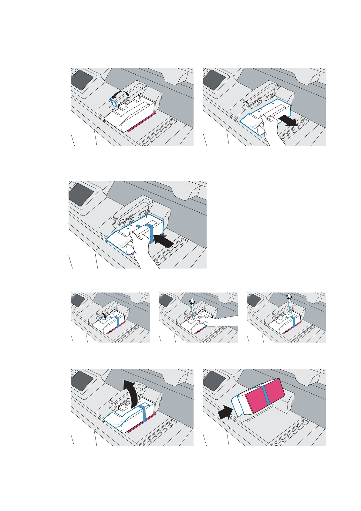
6. Pull the lamp release handle, lift the module, then remove it from the printer. Used lamps can be recycled
through HP's Planet Partners Program, where available. Visit http://www.hp.com/recycle/ for more
information. Where the program is not available, dispose of the lamp according to local regulations.
7. Take the new lamp from its packaging. Do not remove the tape and foam yet.
8. Holding the new lamp module, align it with the hinges on the fusing carriage.
9. Holding each hinge in place, use a T20 screwdriver to replace all four screws.
10. Pull the handle to unlock and rotate the lamp clockwise.
86 Chapter 14 Maintenance ENWW
Page 93

11. Remove the tape and foam from the lamp and wipe any ngerprints o the glass.
12. Push the lever to secure the lamp.
13. Close the top cover.
14. The printer automatically locks the top cover, moves the fusing carriage to its original location, checks the
new lamp status, and calibrates the lamp.
Replace the cleaning roll
The cleaning roll is a roll of absorbent fabric used in the normal operation of the printer to wipe the printheads
periodically: at the beginning and end of printing, while printing, on printhead check and clean, and so on. This
helps the printheads to deliver agents continuously and maintain print quality.
The frequency of replacement depends on your use of the printer. The printer will not print when the cleaning
roll needs to be replaced.
At the printer’s front panel, tap , then Other supplies > Cleaning roll to see the status of the roll.
CAUTION: Do not touch or vacuum the fabric of the printhead cleaning roll. Any interference with the roll may
prevent the printer from keeping track of roll usage, in which case you may see incorrect error messages, and a
printing job may be canceled unnecessarily.
Tools needed
● Explosion-protected vacuum cleaner with a soft brush nozzle
● Nitrile gloves (recommended)
ENWW Replace the cleaning roll 87
Page 94

Procedure
Replace the printhead cleaning roll immediately following the front panel message, to continue printing without
damaging the printhead.
1. Ensure that you have a new cleaning roll ready.
2. Tap Replace cleaning roll on the front panel.
3. Open the top cover.
4. Put on gloves.
5. Ensure that no parts are left in the build chamber and that the print area is clean. See Clean the print area
on page 71 if necessary.
6. Move the print carriage over the platform.
7. Remove the printhead cap by rotating it 20° and pulling it out.
8. Disengage the two latches to release the cleaning roll module.
88 Chapter 14 Maintenance ENWW
Page 95

9. Rotate the handle until it is vertical, then pull it upwards to remove the cleaning roll module from the
printer.
10. Transfer the used roll module to a container or bag and dispose of it according to local regulations.
11. Vacuum the cavity with the explosion-protected vacuum cleaner, using a soft brush nozzle.
12. Remove the packaging from the new module, then orient and insert it into the cavity.
13. Push down, and rotate the handle to close it.
14. Engage the two latches to secure the cleaning roll module.
ENWW Replace the cleaning roll 89
Page 96

CAUTION: Ensure that the latches are pushed down as far as they will go.
15. Reinsert the printhead cap. See Replace the printhead cap on page 107.
16. Move the print carriage back to its original position.
17. Close the top cover.
18. Tap Finish and check on the front panel.
The roll rotates, then the print carriage returns to its home position.
90 Chapter 14 Maintenance ENWW
Page 97

19. Open the top cover to check that two marks appear on the roll. Tap Two marks on the front panel.
If there is only one mark, tap One mark on the front panel; the cleaning roll may have been inserted
incorrectly. Try reinserting the cleaning roll module, and ensure that the latches are fully engaged.
20. When you are sure that the cleaning roll module is working correctly, close the top cover.
21. Dispose of the contents of the vacuum cleaner according to local regulations.
Replace the material reclamation lter
The front panel noties you when the material reclamation lter needs to be replaced. Follow the steps on the
front panel.
Tools needed
● HP 3D400 Air Exhaust Filter
● Nitrile gloves and mask (recommended)
Procedure
1. Open the agent door.
ENWW Replace the material reclamation lter 91
Page 98

2. Check that the waynding LED is on, next to the access door to the material reclamation lter. Open the
material reclamation lter by pushing the top left corner.
3. Unlock the latch, pull it up, then pull out the old lter.
4. Remove the new lter from its packaging.
92 Chapter 14 Maintenance ENWW
Page 99

5. Insert the new lter into the slot.
6. Close the lid and latch it into place.
7. Close the access door.
8. Check that the waynding LED beside the lter is now o.
9. Close the agent door.
10. Tap Finish and check and then OK on the front panel.
11. Dispose of the old lter according to local regulations.
Replace the air exhaust lter
The front panel noties you when the air exhaust lter needs to be replaced. Follow the steps on the front panel.
ENWW Replace the air exhaust lter 93
Page 100

Tools needed
Procedure
● HP 3D400 Air Exhaust Filter
● Nitrile gloves and mask (recommended)
1. Tap Replace air exhaust lter on the front panel.
2. Open the agent door.
3. Open the B5 drawer by pulling the handle.
4. Unlatch the lid and open the compartment.
94 Chapter 14 Maintenance ENWW
 Loading...