

Page 1

hp Integrity rx1600
Operation and Maintenance
Regulatory Model Number: RSVLA-0302
Manufacturing Part Number: rx1600_OpMaint
January 2004
U.S .A .
© Copyright 2004 Hewlett-Packard Development Company, L.P..
Page 2

Legal Notices
Copyright Notices. ©Copyright 2004 Hewlett-Packard Development Company, L.P.
The information contained herein is subject to change without notice. The only warranties for HP products
and services are set forth in the express warranty statements accompanying such products and services.
Nothing herein should be construed as constituting an additional warranty. HP shall not be liable for
technical or editorial errors or omissions contained herein.
Adobe and Acrobat are trademarks of Adobe Systems Incorporated. HP-UX Release 10.20 and later and
HP-UX Release 11.00 and later (in both 32 and 64-bit configurations) on all HP 9000 computers are Open
Group UNIX 95 branded products. Intel and Itanium are trademarks or registered trademarks of Intel
Corporation or its subsidiaries in the United States and other countries. Linux is a registered trademark of
Linus Torvalds. UNIX is a registered trademark of The Open Group. Windows is a registered trademark of
Microsoft Corporation.
Printed in the U.S.A.
Reproduction, adaptation, or translation of this document without prior written permission is prohibited,
except as allowed under the copyright laws.
Related Documents. The HP Server Documentation CD-ROM has been provided with your server. It
contains a complete documentation set for the server, including localized versions of key documents. Included
on the CD-ROM are the Site Preparation and Operations and Maintenance guides, which contain in-depth
troubleshooting, installation, and repair information.
The CD will autorun when you insert it into a Windows® workstation, or, point your browser at the index.htm
file located under the Start directory of the CD. All users, including UNIX®/Linux, can access a complete
manual set by viewing the directory manuals. The manuals are in Adobe® Acrobat® Reader (pdf) format.
In addition, the latest versions of these documents, and any updates to these documents, are posted under the
appropriate server at http://docs.hp.com and http://www.hp.com/support/itaniumservers.
For online access to technical support information, self-solve tools, online assistance, community forums of IT
experts, broad multivendor knowledge base, and monitoring and diagnostic tools, go to
http://www.hp.com/support.
2
Page 3

1. About This Document
What’s in This Document . . . . . . . . . . . . . . . . . . . . . . . . . . . . . . . . . . . . . . . . . . . . . . . . . . . . . . . . . . . . . 13
Typographical Conventions . . . . . . . . . . . . . . . . . . . . . . . . . . . . . . . . . . . . . . . . . . . . . . . . . . . . . . . . . . 13
Related Documents . . . . . . . . . . . . . . . . . . . . . . . . . . . . . . . . . . . . . . . . . . . . . . . . . . . . . . . . . . . . . . . . . . 14
HP Encourages Your Comments . . . . . . . . . . . . . . . . . . . . . . . . . . . . . . . . . . . . . . . . . . . . . . . . . . . . . . . . 14
2. Controls, Ports and Indicators
Control Panel . . . . . . . . . . . . . . . . . . . . . . . . . . . . . . . . . . . . . . . . . . . . . . . . . . . . . . . . . . . . . . . . . . . . . . . 15
Additional Controls and Indicators. . . . . . . . . . . . . . . . . . . . . . . . . . . . . . . . . . . . . . . . . . . . . . . . . . . . . . 16
Hard Disk Drive Indicators . . . . . . . . . . . . . . . . . . . . . . . . . . . . . . . . . . . . . . . . . . . . . . . . . . . . . . . . . . 16
Optional Removable Media Drive . . . . . . . . . . . . . . . . . . . . . . . . . . . . . . . . . . . . . . . . . . . . . . . . . . . . . 17
Rear Panel . . . . . . . . . . . . . . . . . . . . . . . . . . . . . . . . . . . . . . . . . . . . . . . . . . . . . . . . . . . . . . . . . . . . . . . . . 17
10/100/1000 base-T ethernet LAN Connector . . . . . . . . . . . . . . . . . . . . . . . . . . . . . . . . . . . . . . . . . . . . 19
10/100 base-T ethernet LAN Connector . . . . . . . . . . . . . . . . . . . . . . . . . . . . . . . . . . . . . . . . . . . . . . . . 20
Optional Management Processor Card LAN LEDs . . . . . . . . . . . . . . . . . . . . . . . . . . . . . . . . . . . . . . . 20
3. External Connectors
Connector Pinouts . . . . . . . . . . . . . . . . . . . . . . . . . . . . . . . . . . . . . . . . . . . . . . . . . . . . . . . . . . . . . . . . . . . 23
Universal Serial Bus (USB) Ports. . . . . . . . . . . . . . . . . . . . . . . . . . . . . . . . . . . . . . . . . . . . . . . . . . . . . . . 24
Serial Port. . . . . . . . . . . . . . . . . . . . . . . . . . . . . . . . . . . . . . . . . . . . . . . . . . . . . . . . . . . . . . . . . . . . . . . . . . 24
SCSI Port, Ultra 3, 68-Pin . . . . . . . . . . . . . . . . . . . . . . . . . . . . . . . . . . . . . . . . . . . . . . . . . . . . . . . . . . . . . 25
10/100 LAN Connector. . . . . . . . . . . . . . . . . . . . . . . . . . . . . . . . . . . . . . . . . . . . . . . . . . . . . . . . . . . . . . . . 27
10/100/1000 LAN Connector . . . . . . . . . . . . . . . . . . . . . . . . . . . . . . . . . . . . . . . . . . . . . . . . . . . . . . . . . . . 28
Contents
4. Installing and Configuring
Service Tools Required. . . . . . . . . . . . . . . . . . . . . . . . . . . . . . . . . . . . . . . . . . . . . . . . . . . . . . . . . . . . . . . . 29
Installing Internal Hard Disk Drives . . . . . . . . . . . . . . . . . . . . . . . . . . . . . . . . . . . . . . . . . . . . . . . . . . . . 29
Installing Processors and Memory . . . . . . . . . . . . . . . . . . . . . . . . . . . . . . . . . . . . . . . . . . . . . . . . . . . . . . 31
Installing an Additional Processor . . . . . . . . . . . . . . . . . . . . . . . . . . . . . . . . . . . . . . . . . . . . . . . . . . . . 32
Installing Additional Memory . . . . . . . . . . . . . . . . . . . . . . . . . . . . . . . . . . . . . . . . . . . . . . . . . . . . . . . . . . 39
Supported DIMM sizes . . . . . . . . . . . . . . . . . . . . . . . . . . . . . . . . . . . . . . . . . . . . . . . . . . . . . . . . . . . . . . 39
DIMM Locations . . . . . . . . . . . . . . . . . . . . . . . . . . . . . . . . . . . . . . . . . . . . . . . . . . . . . . . . . . . . . . . . . . . 40
Installing DIMMs . . . . . . . . . . . . . . . . . . . . . . . . . . . . . . . . . . . . . . . . . . . . . . . . . . . . . . . . . . . . . . . . . . 41
Installing Additional PCI Cards . . . . . . . . . . . . . . . . . . . . . . . . . . . . . . . . . . . . . . . . . . . . . . . . . . . . . . . . 43
Installing a PCI Card . . . . . . . . . . . . . . . . . . . . . . . . . . . . . . . . . . . . . . . . . . . . . . . . . . . . . . . . . . . . . . . 43
Optional Management Processor Card (MP) . . . . . . . . . . . . . . . . . . . . . . . . . . . . . . . . . . . . . . . . . . . . . . 46
5. Utilities
Extensible Firmware Interface (EFI) Boot Manager . . . . . . . . . . . . . . . . . . . . . . . . . . . . . . . . . . . . . . . . 49
EFI Commands . . . . . . . . . . . . . . . . . . . . . . . . . . . . . . . . . . . . . . . . . . . . . . . . . . . . . . . . . . . . . . . . . . . . 51
EFI/POSSE Commands . . . . . . . . . . . . . . . . . . . . . . . . . . . . . . . . . . . . . . . . . . . . . . . . . . . . . . . . . . . . . . . 53
help . . . . . . . . . . . . . . . . . . . . . . . . . . . . . . . . . . . . . . . . . . . . . . . . . . . . . . . . . . . . . . . . . . . . . . . . . . . . . 53
baud . . . . . . . . . . . . . . . . . . . . . . . . . . . . . . . . . . . . . . . . . . . . . . . . . . . . . . . . . . . . . . . . . . . . . . . . . . . . . 55
boottest . . . . . . . . . . . . . . . . . . . . . . . . . . . . . . . . . . . . . . . . . . . . . . . . . . . . . . . . . . . . . . . . . . . . . . . . . . 55
cpuconfig . . . . . . . . . . . . . . . . . . . . . . . . . . . . . . . . . . . . . . . . . . . . . . . . . . . . . . . . . . . . . . . . . . . . . . . . . 56
default . . . . . . . . . . . . . . . . . . . . . . . . . . . . . . . . . . . . . . . . . . . . . . . . . . . . . . . . . . . . . . . . . . . . . . . . . . . 57
3
Page 4

Contents
errdump. . . . . . . . . . . . . . . . . . . . . . . . . . . . . . . . . . . . . . . . . . . . . . . . . . . . . . . . . . . . . . . . . . . . . . . . . . 58
info . . . . . . . . . . . . . . . . . . . . . . . . . . . . . . . . . . . . . . . . . . . . . . . . . . . . . . . . . . . . . . . . . . . . . . . . . . . . . . 58
lanaddress . . . . . . . . . . . . . . . . . . . . . . . . . . . . . . . . . . . . . . . . . . . . . . . . . . . . . . . . . . . . . . . . . . . . . . . . 64
monarch. . . . . . . . . . . . . . . . . . . . . . . . . . . . . . . . . . . . . . . . . . . . . . . . . . . . . . . . . . . . . . . . . . . . . . . . . . 64
pdt . . . . . . . . . . . . . . . . . . . . . . . . . . . . . . . . . . . . . . . . . . . . . . . . . . . . . . . . . . . . . . . . . . . . . . . . . . . . . . 65
sysmode . . . . . . . . . . . . . . . . . . . . . . . . . . . . . . . . . . . . . . . . . . . . . . . . . . . . . . . . . . . . . . . . . . . . . . . . . . 66
Specifying SCSI Parameters . . . . . . . . . . . . . . . . . . . . . . . . . . . . . . . . . . . . . . . . . . . . . . . . . . . . . . . . . . . 66
Using the SCSI Setup Utility. . . . . . . . . . . . . . . . . . . . . . . . . . . . . . . . . . . . . . . . . . . . . . . . . . . . . . . . . 66
Using the Boot Option Maintenance Menu . . . . . . . . . . . . . . . . . . . . . . . . . . . . . . . . . . . . . . . . . . . . . . . 73
Paths . . . . . . . . . . . . . . . . . . . . . . . . . . . . . . . . . . . . . . . . . . . . . . . . . . . . . . . . . . . . . . . . . . . . . . . . . . . . 73
Using the System Configuration Menu . . . . . . . . . . . . . . . . . . . . . . . . . . . . . . . . . . . . . . . . . . . . . . . . . 80
Management Processor . . . . . . . . . . . . . . . . . . . . . . . . . . . . . . . . . . . . . . . . . . . . . . . . . . . . . . . . . . . . . . . 81
Accessing the Management Processor. . . . . . . . . . . . . . . . . . . . . . . . . . . . . . . . . . . . . . . . . . . . . . . . . . 82
Management Processor Command Interface . . . . . . . . . . . . . . . . . . . . . . . . . . . . . . . . . . . . . . . . . . . . . . 83
MP Welcome Screen . . . . . . . . . . . . . . . . . . . . . . . . . . . . . . . . . . . . . . . . . . . . . . . . . . . . . . . . . . . . . . . . 83
Management Processor Help System . . . . . . . . . . . . . . . . . . . . . . . . . . . . . . . . . . . . . . . . . . . . . . . . . . 83
Management Processor Commands . . . . . . . . . . . . . . . . . . . . . . . . . . . . . . . . . . . . . . . . . . . . . . . . . . . . 84
Reset BMC Passwords . . . . . . . . . . . . . . . . . . . . . . . . . . . . . . . . . . . . . . . . . . . . . . . . . . . . . . . . . . . . . . 85
Configure Serial Port Parameters . . . . . . . . . . . . . . . . . . . . . . . . . . . . . . . . . . . . . . . . . . . . . . . . . . . . . 85
Certificate Generate . . . . . . . . . . . . . . . . . . . . . . . . . . . . . . . . . . . . . . . . . . . . . . . . . . . . . . . . . . . . . . . . 86
Console Log . . . . . . . . . . . . . . . . . . . . . . . . . . . . . . . . . . . . . . . . . . . . . . . . . . . . . . . . . . . . . . . . . . . . . . . 86
Command Mode . . . . . . . . . . . . . . . . . . . . . . . . . . . . . . . . . . . . . . . . . . . . . . . . . . . . . . . . . . . . . . . . . . . 86
Console . . . . . . . . . . . . . . . . . . . . . . . . . . . . . . . . . . . . . . . . . . . . . . . . . . . . . . . . . . . . . . . . . . . . . . . . . . 87
Connect to Service Processor . . . . . . . . . . . . . . . . . . . . . . . . . . . . . . . . . . . . . . . . . . . . . . . . . . . . . . . . . 87
Date . . . . . . . . . . . . . . . . . . . . . . . . . . . . . . . . . . . . . . . . . . . . . . . . . . . . . . . . . . . . . . . . . . . . . . . . . . . . . 87
Default Configuration. . . . . . . . . . . . . . . . . . . . . . . . . . . . . . . . . . . . . . . . . . . . . . . . . . . . . . . . . . . . . . . 87
Display FRUID . . . . . . . . . . . . . . . . . . . . . . . . . . . . . . . . . . . . . . . . . . . . . . . . . . . . . . . . . . . . . . . . . . . . 88
Disconnect Remote or LAN Console . . . . . . . . . . . . . . . . . . . . . . . . . . . . . . . . . . . . . . . . . . . . . . . . . . . 88
MP Firmware Update. . . . . . . . . . . . . . . . . . . . . . . . . . . . . . . . . . . . . . . . . . . . . . . . . . . . . . . . . . . . . . . 88
Help . . . . . . . . . . . . . . . . . . . . . . . . . . . . . . . . . . . . . . . . . . . . . . . . . . . . . . . . . . . . . . . . . . . . . . . . . . . . . 88
Display System ID . . . . . . . . . . . . . . . . . . . . . . . . . . . . . . . . . . . . . . . . . . . . . . . . . . . . . . . . . . . . . . . . . 88
Inactivity Timeout . . . . . . . . . . . . . . . . . . . . . . . . . . . . . . . . . . . . . . . . . . . . . . . . . . . . . . . . . . . . . . . . . 88
Configure LAN Console . . . . . . . . . . . . . . . . . . . . . . . . . . . . . . . . . . . . . . . . . . . . . . . . . . . . . . . . . . . . . 89
Locator LED Status . . . . . . . . . . . . . . . . . . . . . . . . . . . . . . . . . . . . . . . . . . . . . . . . . . . . . . . . . . . . . . . . 89
LAN Status . . . . . . . . . . . . . . . . . . . . . . . . . . . . . . . . . . . . . . . . . . . . . . . . . . . . . . . . . . . . . . . . . . . . . . . 89
Return to Main Menu . . . . . . . . . . . . . . . . . . . . . . . . . . . . . . . . . . . . . . . . . . . . . . . . . . . . . . . . . . . . . . . 89
Modem Reset. . . . . . . . . . . . . . . . . . . . . . . . . . . . . . . . . . . . . . . . . . . . . . . . . . . . . . . . . . . . . . . . . . . . . . 89
Modem Status . . . . . . . . . . . . . . . . . . . . . . . . . . . . . . . . . . . . . . . . . . . . . . . . . . . . . . . . . . . . . . . . . . . . . 89
Power Control . . . . . . . . . . . . . . . . . . . . . . . . . . . . . . . . . . . . . . . . . . . . . . . . . . . . . . . . . . . . . . . . . . . . . 90
Configure Paging . . . . . . . . . . . . . . . . . . . . . . . . . . . . . . . . . . . . . . . . . . . . . . . . . . . . . . . . . . . . . . . . . . 90
Power Status . . . . . . . . . . . . . . . . . . . . . . . . . . . . . . . . . . . . . . . . . . . . . . . . . . . . . . . . . . . . . . . . . . . . . . 90
Reset BMC. . . . . . . . . . . . . . . . . . . . . . . . . . . . . . . . . . . . . . . . . . . . . . . . . . . . . . . . . . . . . . . . . . . . . . . . 90
Reset System . . . . . . . . . . . . . . . . . . . . . . . . . . . . . . . . . . . . . . . . . . . . . . . . . . . . . . . . . . . . . . . . . . . . . . 90
Set Access . . . . . . . . . . . . . . . . . . . . . . . . . . . . . . . . . . . . . . . . . . . . . . . . . . . . . . . . . . . . . . . . . . . . . . . . 90
Create Local Session. . . . . . . . . . . . . . . . . . . . . . . . . . . . . . . . . . . . . . . . . . . . . . . . . . . . . . . . . . . . . . . . 91
Display Logs . . . . . . . . . . . . . . . . . . . . . . . . . . . . . . . . . . . . . . . . . . . . . . . . . . . . . . . . . . . . . . . . . . . . . . 91
4
Page 5

Security Options . . . . . . . . . . . . . . . . . . . . . . . . . . . . . . . . . . . . . . . . . . . . . . . . . . . . . . . . . . . . . . . . . . . 92
System Status . . . . . . . . . . . . . . . . . . . . . . . . . . . . . . . . . . . . . . . . . . . . . . . . . . . . . . . . . . . . . . . . . . . . . 92
Firmware Revision Status . . . . . . . . . . . . . . . . . . . . . . . . . . . . . . . . . . . . . . . . . . . . . . . . . . . . . . . . . . . 92
Transfer Of Control . . . . . . . . . . . . . . . . . . . . . . . . . . . . . . . . . . . . . . . . . . . . . . . . . . . . . . . . . . . . . . . . 93
Tell. . . . . . . . . . . . . . . . . . . . . . . . . . . . . . . . . . . . . . . . . . . . . . . . . . . . . . . . . . . . . . . . . . . . . . . . . . . . . . 93
User Configuration . . . . . . . . . . . . . . . . . . . . . . . . . . . . . . . . . . . . . . . . . . . . . . . . . . . . . . . . . . . . . . . . . 93
Virtual Front Panel. . . . . . . . . . . . . . . . . . . . . . . . . . . . . . . . . . . . . . . . . . . . . . . . . . . . . . . . . . . . . . . . . 93
Who . . . . . . . . . . . . . . . . . . . . . . . . . . . . . . . . . . . . . . . . . . . . . . . . . . . . . . . . . . . . . . . . . . . . . . . . . . . . . 93
Exit from MP. . . . . . . . . . . . . . . . . . . . . . . . . . . . . . . . . . . . . . . . . . . . . . . . . . . . . . . . . . . . . . . . . . . . . . 94
Diagnostics . . . . . . . . . . . . . . . . . . . . . . . . . . . . . . . . . . . . . . . . . . . . . . . . . . . . . . . . . . . . . . . . . . . . . . . 94
6. Troubleshooting
Troubleshooting Tips . . . . . . . . . . . . . . . . . . . . . . . . . . . . . . . . . . . . . . . . . . . . . . . . . . . . . . . . . . . . . . . . . 95
Troubleshooting Methodology . . . . . . . . . . . . . . . . . . . . . . . . . . . . . . . . . . . . . . . . . . . . . . . . . . . . . . . . 95
Possible Problems. . . . . . . . . . . . . . . . . . . . . . . . . . . . . . . . . . . . . . . . . . . . . . . . . . . . . . . . . . . . . . . . . . . . 96
The system will not power-up. . . . . . . . . . . . . . . . . . . . . . . . . . . . . . . . . . . . . . . . . . . . . . . . . . . . . . . . . 96
The system will not boot. . . . . . . . . . . . . . . . . . . . . . . . . . . . . . . . . . . . . . . . . . . . . . . . . . . . . . . . . . . . . 97
The system has intermittent failures. . . . . . . . . . . . . . . . . . . . . . . . . . . . . . . . . . . . . . . . . . . . . . . . . . . 97
The system LED or diagnostic LEDs are not on and no error messages appear. . . . . . . . . . . . . . . . . 98
Power goes off on the server and does not come back on. . . . . . . . . . . . . . . . . . . . . . . . . . . . . . . . . . . . 98
Troubleshooting and FRU identification . . . . . . . . . . . . . . . . . . . . . . . . . . . . . . . . . . . . . . . . . . . . . . . . 100
Verifying Hard Disk Drive Operation . . . . . . . . . . . . . . . . . . . . . . . . . . . . . . . . . . . . . . . . . . . . . . . . . . . 102
Identifying and Diagnosing Hardware Problems. . . . . . . . . . . . . . . . . . . . . . . . . . . . . . . . . . . . . . . . . . 104
Power and System LEDs . . . . . . . . . . . . . . . . . . . . . . . . . . . . . . . . . . . . . . . . . . . . . . . . . . . . . . . . . . . 104
Command Line Interface . . . . . . . . . . . . . . . . . . . . . . . . . . . . . . . . . . . . . . . . . . . . . . . . . . . . . . . . . . . . . 116
Command Line Interface Menu . . . . . . . . . . . . . . . . . . . . . . . . . . . . . . . . . . . . . . . . . . . . . . . . . . . . . . 116
Troubleshooting Example Using CLI . . . . . . . . . . . . . . . . . . . . . . . . . . . . . . . . . . . . . . . . . . . . . . . . . 117
Troubleshooting Example Using CLI . . . . . . . . . . . . . . . . . . . . . . . . . . . . . . . . . . . . . . . . . . . . . . . . . 117
LAN LEDs . . . . . . . . . . . . . . . . . . . . . . . . . . . . . . . . . . . . . . . . . . . . . . . . . . . . . . . . . . . . . . . . . . . . . . . . 118
Rear Panel LAN LEDs . . . . . . . . . . . . . . . . . . . . . . . . . . . . . . . . . . . . . . . . . . . . . . . . . . . . . . . . . . . . . 118
System Management 10/100 Mb LAN. . . . . . . . . . . . . . . . . . . . . . . . . . . . . . . . . . . . . . . . . . . . . . . . . 118
Optional Management Processor LAN LEDs . . . . . . . . . . . . . . . . . . . . . . . . . . . . . . . . . . . . . . . . . . . 119
System Board Diagnostic LEDs . . . . . . . . . . . . . . . . . . . . . . . . . . . . . . . . . . . . . . . . . . . . . . . . . . . . . . . 120
Running Diagnostic Software Tools . . . . . . . . . . . . . . . . . . . . . . . . . . . . . . . . . . . . . . . . . . . . . . . . . . . . 121
HP e-DiagTools Hardware Diagnostics . . . . . . . . . . . . . . . . . . . . . . . . . . . . . . . . . . . . . . . . . . . . . . . . 121
Offline Diagnostics Environment (ODE) . . . . . . . . . . . . . . . . . . . . . . . . . . . . . . . . . . . . . . . . . . . . . . . 124
Using Offline Diagnostic Tools . . . . . . . . . . . . . . . . . . . . . . . . . . . . . . . . . . . . . . . . . . . . . . . . . . . . . . . . 125
E-DiagTools . . . . . . . . . . . . . . . . . . . . . . . . . . . . . . . . . . . . . . . . . . . . . . . . . . . . . . . . . . . . . . . . . . . . . . 125
Offline Diagnostic Environment (ODE). . . . . . . . . . . . . . . . . . . . . . . . . . . . . . . . . . . . . . . . . . . . . . . . 126
Recommended Cleaning Procedures . . . . . . . . . . . . . . . . . . . . . . . . . . . . . . . . . . . . . . . . . . . . . . . . . . . . 126
Where to Get Help . . . . . . . . . . . . . . . . . . . . . . . . . . . . . . . . . . . . . . . . . . . . . . . . . . . . . . . . . . . . . . . . . . 126
Information to Collect Before you Contact Support . . . . . . . . . . . . . . . . . . . . . . . . . . . . . . . . . . . . . . 127
Online Support . . . . . . . . . . . . . . . . . . . . . . . . . . . . . . . . . . . . . . . . . . . . . . . . . . . . . . . . . . . . . . . . . . . 127
Phone Support. . . . . . . . . . . . . . . . . . . . . . . . . . . . . . . . . . . . . . . . . . . . . . . . . . . . . . . . . . . . . . . . . . . . 127
Contents
7. Removing and Replacing Components
5
Page 6

Contents
Safety Information . . . . . . . . . . . . . . . . . . . . . . . . . . . . . . . . . . . . . . . . . . . . . . . . . . . . . . . . . . . . . . . . . . 129
Service Tools Required. . . . . . . . . . . . . . . . . . . . . . . . . . . . . . . . . . . . . . . . . . . . . . . . . . . . . . . . . . . . . . . 129
Accessing a Rack Mounted Server . . . . . . . . . . . . . . . . . . . . . . . . . . . . . . . . . . . . . . . . . . . . . . . . . . . . . 129
Extend the Server from the Rack. . . . . . . . . . . . . . . . . . . . . . . . . . . . . . . . . . . . . . . . . . . . . . . . . . . . . 130
Insert the Server into the Rack . . . . . . . . . . . . . . . . . . . . . . . . . . . . . . . . . . . . . . . . . . . . . . . . . . . . . . 130
Removing and Replacing the Front Bezel. . . . . . . . . . . . . . . . . . . . . . . . . . . . . . . . . . . . . . . . . . . . . . . . 131
Removing the Front Bezel . . . . . . . . . . . . . . . . . . . . . . . . . . . . . . . . . . . . . . . . . . . . . . . . . . . . . . . . . . 131
Replacing the Front Bezel . . . . . . . . . . . . . . . . . . . . . . . . . . . . . . . . . . . . . . . . . . . . . . . . . . . . . . . . . . 131
Removing and Replacing the Cover . . . . . . . . . . . . . . . . . . . . . . . . . . . . . . . . . . . . . . . . . . . . . . . . . . . . 132
Removing the Cover . . . . . . . . . . . . . . . . . . . . . . . . . . . . . . . . . . . . . . . . . . . . . . . . . . . . . . . . . . . . . . . 133
Replacing the Cover . . . . . . . . . . . . . . . . . . . . . . . . . . . . . . . . . . . . . . . . . . . . . . . . . . . . . . . . . . . . . . . 133
Removing and Replacing System Memory . . . . . . . . . . . . . . . . . . . . . . . . . . . . . . . . . . . . . . . . . . . . . . . 134
Supported DIMM Sizes . . . . . . . . . . . . . . . . . . . . . . . . . . . . . . . . . . . . . . . . . . . . . . . . . . . . . . . . . . . . 135
Removing System Memory . . . . . . . . . . . . . . . . . . . . . . . . . . . . . . . . . . . . . . . . . . . . . . . . . . . . . . . . . . 135
Installing System Memory . . . . . . . . . . . . . . . . . . . . . . . . . . . . . . . . . . . . . . . . . . . . . . . . . . . . . . . . . . 135
Removing and Replacing a Processor . . . . . . . . . . . . . . . . . . . . . . . . . . . . . . . . . . . . . . . . . . . . . . . . . . . 136
Removing a Processor . . . . . . . . . . . . . . . . . . . . . . . . . . . . . . . . . . . . . . . . . . . . . . . . . . . . . . . . . . . . . . 138
Replacing a Processor . . . . . . . . . . . . . . . . . . . . . . . . . . . . . . . . . . . . . . . . . . . . . . . . . . . . . . . . . . . . . . 142
Removing and Replacing the System Battery . . . . . . . . . . . . . . . . . . . . . . . . . . . . . . . . . . . . . . . . . . . . 146
Removing the System Battery . . . . . . . . . . . . . . . . . . . . . . . . . . . . . . . . . . . . . . . . . . . . . . . . . . . . . . . 146
Replacing the System Battery . . . . . . . . . . . . . . . . . . . . . . . . . . . . . . . . . . . . . . . . . . . . . . . . . . . . . . . 147
Removing and Replacing Fan Units . . . . . . . . . . . . . . . . . . . . . . . . . . . . . . . . . . . . . . . . . . . . . . . . . . . . 148
Removing the Power Supply Fan Unit . . . . . . . . . . . . . . . . . . . . . . . . . . . . . . . . . . . . . . . . . . . . . . . . 148
Replacing the Power Supply Fan Unit. . . . . . . . . . . . . . . . . . . . . . . . . . . . . . . . . . . . . . . . . . . . . . . . . 149
Removing a Chassis Fan Unit . . . . . . . . . . . . . . . . . . . . . . . . . . . . . . . . . . . . . . . . . . . . . . . . . . . . . . . 149
Replacing a Chassis Fan Unit . . . . . . . . . . . . . . . . . . . . . . . . . . . . . . . . . . . . . . . . . . . . . . . . . . . . . . . 150
Removing and Replacing the Display Panel. . . . . . . . . . . . . . . . . . . . . . . . . . . . . . . . . . . . . . . . . . . . . . 151
Removing the Display Panel . . . . . . . . . . . . . . . . . . . . . . . . . . . . . . . . . . . . . . . . . . . . . . . . . . . . . . . . 151
Replacing the Display Panel . . . . . . . . . . . . . . . . . . . . . . . . . . . . . . . . . . . . . . . . . . . . . . . . . . . . . . . . 152
Removing and Replacing the PCI I/O Riser Assembly . . . . . . . . . . . . . . . . . . . . . . . . . . . . . . . . . . . . . 153
Removing the PCI I/O Riser Assembly . . . . . . . . . . . . . . . . . . . . . . . . . . . . . . . . . . . . . . . . . . . . . . . . 153
Replacing the PCI I/O Riser Assembly . . . . . . . . . . . . . . . . . . . . . . . . . . . . . . . . . . . . . . . . . . . . . . . . 155
Removing and Replacing PCI Cards . . . . . . . . . . . . . . . . . . . . . . . . . . . . . . . . . . . . . . . . . . . . . . . . . . . . 155
Removing a PCI Card . . . . . . . . . . . . . . . . . . . . . . . . . . . . . . . . . . . . . . . . . . . . . . . . . . . . . . . . . . . . . . 156
Replacing a PCI Card . . . . . . . . . . . . . . . . . . . . . . . . . . . . . . . . . . . . . . . . . . . . . . . . . . . . . . . . . . . . . . 158
Removing and Replacing an Internal Hard Disk Drive. . . . . . . . . . . . . . . . . . . . . . . . . . . . . . . . . . . . . 158
Removing an Internal Hard Disk Drive . . . . . . . . . . . . . . . . . . . . . . . . . . . . . . . . . . . . . . . . . . . . . . . 159
Replacing an Internal Hard Disk Drive . . . . . . . . . . . . . . . . . . . . . . . . . . . . . . . . . . . . . . . . . . . . . . . 160
Removing and Replacing the Power Supply . . . . . . . . . . . . . . . . . . . . . . . . . . . . . . . . . . . . . . . . . . . . . . 161
Removing the Power Supply . . . . . . . . . . . . . . . . . . . . . . . . . . . . . . . . . . . . . . . . . . . . . . . . . . . . . . . . 162
Replacing the Power Supply. . . . . . . . . . . . . . . . . . . . . . . . . . . . . . . . . . . . . . . . . . . . . . . . . . . . . . . . . 162
Removing and Replacing a Removable Media Drive . . . . . . . . . . . . . . . . . . . . . . . . . . . . . . . . . . . . . . . 163
Removing a Removable Media Drive. . . . . . . . . . . . . . . . . . . . . . . . . . . . . . . . . . . . . . . . . . . . . . . . . . 164
Replacing a Removable Media Drive . . . . . . . . . . . . . . . . . . . . . . . . . . . . . . . . . . . . . . . . . . . . . . . . . . 165
Removing and Replacing the Optional Management Processor Card . . . . . . . . . . . . . . . . . . . . . . . . . 166
Removing the Optional Management Processor Card . . . . . . . . . . . . . . . . . . . . . . . . . . . . . . . . . . . . 166
6
Page 7

Replacing the Optional Management Processor Card . . . . . . . . . . . . . . . . . . . . . . . . . . . . . . . . . . . . 166
Removing and Replacing the Optional Management Processor Card Battery. . . . . . . . . . . . . . . . . . . 168
Removing the Optional Management Processor Card Battery . . . . . . . . . . . . . . . . . . . . . . . . . . . . . 168
Replacing the Optional Management Processor Card Battery . . . . . . . . . . . . . . . . . . . . . . . . . . . . . 169
Replacing the Base Unit . . . . . . . . . . . . . . . . . . . . . . . . . . . . . . . . . . . . . . . . . . . . . . . . . . . . . . . . . . . . . 169
8. Parts Information
Field Replaceable Parts (FRU) List . . . . . . . . . . . . . . . . . . . . . . . . . . . . . . . . . . . . . . . . . . . . . . . . . . . . 173
9. Specifications
Hardware Specifications . . . . . . . . . . . . . . . . . . . . . . . . . . . . . . . . . . . . . . . . . . . . . . . . . . . . . . . . . . . . . 179
Dimensions and Weights . . . . . . . . . . . . . . . . . . . . . . . . . . . . . . . . . . . . . . . . . . . . . . . . . . . . . . . . . . . . . 180
Component Dimensions . . . . . . . . . . . . . . . . . . . . . . . . . . . . . . . . . . . . . . . . . . . . . . . . . . . . . . . . . . . . 180
A. System Information
Features Summary. . . . . . . . . . . . . . . . . . . . . . . . . . . . . . . . . . . . . . . . . . . . . . . . . . . . . . . . . . . . . . . . . . 181
Processor . . . . . . . . . . . . . . . . . . . . . . . . . . . . . . . . . . . . . . . . . . . . . . . . . . . . . . . . . . . . . . . . . . . . . . . . 181
Memory . . . . . . . . . . . . . . . . . . . . . . . . . . . . . . . . . . . . . . . . . . . . . . . . . . . . . . . . . . . . . . . . . . . . . . . . . 181
I/O Expansion . . . . . . . . . . . . . . . . . . . . . . . . . . . . . . . . . . . . . . . . . . . . . . . . . . . . . . . . . . . . . . . . . . . . 181
Internal Core I/O. . . . . . . . . . . . . . . . . . . . . . . . . . . . . . . . . . . . . . . . . . . . . . . . . . . . . . . . . . . . . . . . . . 181
External core I/O. . . . . . . . . . . . . . . . . . . . . . . . . . . . . . . . . . . . . . . . . . . . . . . . . . . . . . . . . . . . . . . . . . 181
Power supply unit . . . . . . . . . . . . . . . . . . . . . . . . . . . . . . . . . . . . . . . . . . . . . . . . . . . . . . . . . . . . . . . . . 182
Motherboard manageability. . . . . . . . . . . . . . . . . . . . . . . . . . . . . . . . . . . . . . . . . . . . . . . . . . . . . . . . . 182
Enhanced server manageability, provided by the optional Management Processor (MP) card . . . . 182
Internal Disk Storage Options . . . . . . . . . . . . . . . . . . . . . . . . . . . . . . . . . . . . . . . . . . . . . . . . . . . . . . . 182
Internal Removable Media Options. . . . . . . . . . . . . . . . . . . . . . . . . . . . . . . . . . . . . . . . . . . . . . . . . . . 182
System Board . . . . . . . . . . . . . . . . . . . . . . . . . . . . . . . . . . . . . . . . . . . . . . . . . . . . . . . . . . . . . . . . . . . . . . 183
System Board Components . . . . . . . . . . . . . . . . . . . . . . . . . . . . . . . . . . . . . . . . . . . . . . . . . . . . . . . . . 183
Intel Itanium 2 Processor . . . . . . . . . . . . . . . . . . . . . . . . . . . . . . . . . . . . . . . . . . . . . . . . . . . . . . . . . . . 184
Processor Bus . . . . . . . . . . . . . . . . . . . . . . . . . . . . . . . . . . . . . . . . . . . . . . . . . . . . . . . . . . . . . . . . . . . . 184
I/O and Memory Controller . . . . . . . . . . . . . . . . . . . . . . . . . . . . . . . . . . . . . . . . . . . . . . . . . . . . . . . . . 184
Memory Architecture . . . . . . . . . . . . . . . . . . . . . . . . . . . . . . . . . . . . . . . . . . . . . . . . . . . . . . . . . . . . . . 184
I/O Bus Interface. . . . . . . . . . . . . . . . . . . . . . . . . . . . . . . . . . . . . . . . . . . . . . . . . . . . . . . . . . . . . . . . . . 187
Processor Dependent Hardware Controller. . . . . . . . . . . . . . . . . . . . . . . . . . . . . . . . . . . . . . . . . . . . . 187
Dual Serial Controller . . . . . . . . . . . . . . . . . . . . . . . . . . . . . . . . . . . . . . . . . . . . . . . . . . . . . . . . . . . . . 188
Field Programmable Gate Array . . . . . . . . . . . . . . . . . . . . . . . . . . . . . . . . . . . . . . . . . . . . . . . . . . . . . 188
Baseboard Management Controller. . . . . . . . . . . . . . . . . . . . . . . . . . . . . . . . . . . . . . . . . . . . . . . . . . . 189
SCSI Controller. . . . . . . . . . . . . . . . . . . . . . . . . . . . . . . . . . . . . . . . . . . . . . . . . . . . . . . . . . . . . . . . . . . 189
IDE Interface . . . . . . . . . . . . . . . . . . . . . . . . . . . . . . . . . . . . . . . . . . . . . . . . . . . . . . . . . . . . . . . . . . . . 189
10/100 BT Standard/Management LAN . . . . . . . . . . . . . . . . . . . . . . . . . . . . . . . . . . . . . . . . . . . . . . . 189
1Gb System LAN . . . . . . . . . . . . . . . . . . . . . . . . . . . . . . . . . . . . . . . . . . . . . . . . . . . . . . . . . . . . . . . . . 190
USB Connectors . . . . . . . . . . . . . . . . . . . . . . . . . . . . . . . . . . . . . . . . . . . . . . . . . . . . . . . . . . . . . . . . . . 190
Contents
B. Event, Error, and Warning Messages
EFI Error and Warning Messages . . . . . . . . . . . . . . . . . . . . . . . . . . . . . . . . . . . . . . . . . . . . . . . . . . . . . 191
SEL and FPL Log Entries . . . . . . . . . . . . . . . . . . . . . . . . . . . . . . . . . . . . . . . . . . . . . . . . . . . . . . . . . . 194
7
Page 8

Contents
Accessing the logs with MP commands . . . . . . . . . . . . . . . . . . . . . . . . . . . . . . . . . . . . . . . . . . . . . . . . 197
System Specific Events. . . . . . . . . . . . . . . . . . . . . . . . . . . . . . . . . . . . . . . . . . . . . . . . . . . . . . . . . . . . . 198
Chassis Control Event Codes . . . . . . . . . . . . . . . . . . . . . . . . . . . . . . . . . . . . . . . . . . . . . . . . . . . . . . . . 198
Events Without Sensors . . . . . . . . . . . . . . . . . . . . . . . . . . . . . . . . . . . . . . . . . . . . . . . . . . . . . . . . . . . . 200
Index . . . . . . . . . . . . . . . . . . . . . . . . . . . . . . . . . . . . . . . . . . . . . . . . . . . . . . . . . . . . . . . . . . . . . . 201
8
Page 9

Figures
Figure 2-1. Front View . . . . . . . . . . . . . . . . . . . . . . . . . . . . . . . . . . . . . . . . . . . . . . . . . . . . . . . . . . . . . 15
Figure 2-2. Control Panel. . . . . . . . . . . . . . . . . . . . . . . . . . . . . . . . . . . . . . . . . . . . . . . . . . . . . . . . . . . 15
Figure 2-3. Hard Disk Drive LED Indicators . . . . . . . . . . . . . . . . . . . . . . . . . . . . . . . . . . . . . . . . . . . 17
Figure 2-4. DVD . . . . . . . . . . . . . . . . . . . . . . . . . . . . . . . . . . . . . . . . . . . . . . . . . . . . . . . . . . . . . . . . . . 17
Figure 2-5. Rear View . . . . . . . . . . . . . . . . . . . . . . . . . . . . . . . . . . . . . . . . . . . . . . . . . . . . . . . . . . . . . 18
Figure 2-6. 10/100/1000 base-T ethernet LAN Connector LEDs. . . . . . . . . . . . . . . . . . . . . . . . . . . . 19
Figure 2-7. 10/100 base-T ethernet LAN Connector LEDs . . . . . . . . . . . . . . . . . . . . . . . . . . . . . . . . 20
Figure 2-8. Optional Management Processor Card LAN LEDs. . . . . . . . . . . . . . . . . . . . . . . . . . . . . 20
Figure 3-1. Rear View of Server . . . . . . . . . . . . . . . . . . . . . . . . . . . . . . . . . . . . . . . . . . . . . . . . . . . . . 23
Figure 3-2. Dual USB Port Connector. . . . . . . . . . . . . . . . . . . . . . . . . . . . . . . . . . . . . . . . . . . . . . . . . 24
Figure 3-3. Serial Port Connector . . . . . . . . . . . . . . . . . . . . . . . . . . . . . . . . . . . . . . . . . . . . . . . . . . . . 24
Figure 3-4. SCSI Port, Ultra 3, 68-Pin . . . . . . . . . . . . . . . . . . . . . . . . . . . . . . . . . . . . . . . . . . . . . . . . 25
Figure 3-5. 10/100 LAN Connector . . . . . . . . . . . . . . . . . . . . . . . . . . . . . . . . . . . . . . . . . . . . . . . . . . . 27
Figure 3-6. 10/100/1000 LAN Connector. . . . . . . . . . . . . . . . . . . . . . . . . . . . . . . . . . . . . . . . . . . . . . . 28
Figure 4-1. Front View of the hp Integrity rx1600 Server. . . . . . . . . . . . . . . . . . . . . . . . . . . . . . . . . 29
Figure 4-2. Filler Removal from Slot 1 . . . . . . . . . . . . . . . . . . . . . . . . . . . . . . . . . . . . . . . . . . . . . . . . 30
Figure 4-3. Disk Drive Installation in Slot 1 . . . . . . . . . . . . . . . . . . . . . . . . . . . . . . . . . . . . . . . . . . . 31
Figure 4-4. Processor Location . . . . . . . . . . . . . . . . . . . . . . . . . . . . . . . . . . . . . . . . . . . . . . . . . . . . . . 33
Figure 4-5. Removing the Airflow Blocker . . . . . . . . . . . . . . . . . . . . . . . . . . . . . . . . . . . . . . . . . . . . . 34
Figure 4-6. Unlocking the Processor Locking Mechanism . . . . . . . . . . . . . . . . . . . . . . . . . . . . . . . . . 35
Figure 4-7. Aligning the Processor Assembly . . . . . . . . . . . . . . . . . . . . . . . . . . . . . . . . . . . . . . . . . . . 36
Figure 4-8. Locking the Processor Assembly in Place . . . . . . . . . . . . . . . . . . . . . . . . . . . . . . . . . . . . 36
Figure 4-9. Installing the Sequencer Retaining Cover. . . . . . . . . . . . . . . . . . . . . . . . . . . . . . . . . . . . 37
Figure 4-10. Securing the Sequencer Retaining Cover . . . . . . . . . . . . . . . . . . . . . . . . . . . . . . . . . . . 37
Figure 4-11. Connecting the Processor Power Pod. . . . . . . . . . . . . . . . . . . . . . . . . . . . . . . . . . . . . . . 38
Figure 4-12. Securing the Processor Power Pod . . . . . . . . . . . . . . . . . . . . . . . . . . . . . . . . . . . . . . . . . 38
Figure 4-13. Connecting the Power Cable. . . . . . . . . . . . . . . . . . . . . . . . . . . . . . . . . . . . . . . . . . . . . . 39
Figure 4-14. DIMM Loading Order . . . . . . . . . . . . . . . . . . . . . . . . . . . . . . . . . . . . . . . . . . . . . . . . . . . 40
Figure 4-15. DIMM Locations . . . . . . . . . . . . . . . . . . . . . . . . . . . . . . . . . . . . . . . . . . . . . . . . . . . . . . . 41
Figure 4-16. Inserting DIMM into Memory Slot . . . . . . . . . . . . . . . . . . . . . . . . . . . . . . . . . . . . . . . . 42
Figure 4-17. Using Jackscrew to Release PCI I/O Riser . . . . . . . . . . . . . . . . . . . . . . . . . . . . . . . . . . 44
Figure 4-18. Removing the PCI I/O Riser Assembly . . . . . . . . . . . . . . . . . . . . . . . . . . . . . . . . . . . . . 44
Figure 4-19. Removing a PCI Slot Cover . . . . . . . . . . . . . . . . . . . . . . . . . . . . . . . . . . . . . . . . . . . . . . 45
Figure 4-20. Installing a PCI Card . . . . . . . . . . . . . . . . . . . . . . . . . . . . . . . . . . . . . . . . . . . . . . . . . . . 45
Figure 4-21. Removing the MP Card Blank . . . . . . . . . . . . . . . . . . . . . . . . . . . . . . . . . . . . . . . . . . . . 46
Figure 4-22. Connecting the Management Processor Card . . . . . . . . . . . . . . . . . . . . . . . . . . . . . . . . 47
Figure 4-23. Installing the External Mounting Posts . . . . . . . . . . . . . . . . . . . . . . . . . . . . . . . . . . . . 48
Figure 5-1. EFI Boot Sequence . . . . . . . . . . . . . . . . . . . . . . . . . . . . . . . . . . . . . . . . . . . . . . . . . . . . . . 49
Figure 5-2. Password Reset Jumper . . . . . . . . . . . . . . . . . . . . . . . . . . . . . . . . . . . . . . . . . . . . . . . . . . 81
Figure 6-1. LED Apertures on Hard Disk Drive . . . . . . . . . . . . . . . . . . . . . . . . . . . . . . . . . . . . . . . 103
Figure 6-2. Diagnostic LEDs . . . . . . . . . . . . . . . . . . . . . . . . . . . . . . . . . . . . . . . . . . . . . . . . . . . . . . . 110
Figure 6-3. Location of the STBY, F/W and BMC LEDs . . . . . . . . . . . . . . . . . . . . . . . . . . . . . . . . . 120
Figure 7-1. Front Bezel . . . . . . . . . . . . . . . . . . . . . . . . . . . . . . . . . . . . . . . . . . . . . . . . . . . . . . . . . . . 131
9
Page 10

Figures
Figure 7-2. Removing and Replacing the Cover . . . . . . . . . . . . . . . . . . . . . . . . . . . . . . . . . . . . . . . . 132
Figure 7-3. Aligning the Cover . . . . . . . . . . . . . . . . . . . . . . . . . . . . . . . . . . . . . . . . . . . . . . . . . . . . . 133
Figure 7-4. Closing the Cover . . . . . . . . . . . . . . . . . . . . . . . . . . . . . . . . . . . . . . . . . . . . . . . . . . . . . . 134
Figure 7-5. DIMM Slot Identification . . . . . . . . . . . . . . . . . . . . . . . . . . . . . . . . . . . . . . . . . . . . . . . . 135
Figure 7-6. Inserting a DIMM into Slot . . . . . . . . . . . . . . . . . . . . . . . . . . . . . . . . . . . . . . . . . . . . . . 136
Figure 7-7. Processor Location . . . . . . . . . . . . . . . . . . . . . . . . . . . . . . . . . . . . . . . . . . . . . . . . . . . . . 137
Figure 7-8. Disconnect the Power Cable . . . . . . . . . . . . . . . . . . . . . . . . . . . . . . . . . . . . . . . . . . . . . . 138
Figure 7-9. Remove the Processor Power Pod Mounting Screws. . . . . . . . . . . . . . . . . . . . . . . . . . . 138
Figure 7-10. Disconnecting the Processor Power Pod . . . . . . . . . . . . . . . . . . . . . . . . . . . . . . . . . . . 139
Figure 7-11. Removing the Power Pod . . . . . . . . . . . . . . . . . . . . . . . . . . . . . . . . . . . . . . . . . . . . . . . 139
Figure 7-12. Releasing the Sequencing Retainer . . . . . . . . . . . . . . . . . . . . . . . . . . . . . . . . . . . . . . . 140
Figure 7-13. Removing the Sequencing Retainer . . . . . . . . . . . . . . . . . . . . . . . . . . . . . . . . . . . . . . . 140
Figure 7-14. Unlock the Processor Socket. . . . . . . . . . . . . . . . . . . . . . . . . . . . . . . . . . . . . . . . . . . . . 141
Figure 7-15. Removing the Processor . . . . . . . . . . . . . . . . . . . . . . . . . . . . . . . . . . . . . . . . . . . . . . . . 141
Figure 7-16. Unlocking the Processor Locking Mechanism . . . . . . . . . . . . . . . . . . . . . . . . . . . . . . . 142
Figure 7-17. Aligning the Processor Assembly . . . . . . . . . . . . . . . . . . . . . . . . . . . . . . . . . . . . . . . . . 143
Figure 7-18. Locking the Processor Assembly in Place . . . . . . . . . . . . . . . . . . . . . . . . . . . . . . . . . . 143
Figure 7-19. Installing the Sequencer Retaining Cover. . . . . . . . . . . . . . . . . . . . . . . . . . . . . . . . . . 144
Figure 7-20. Installing the Sequencer Retaining Cover. . . . . . . . . . . . . . . . . . . . . . . . . . . . . . . . . . 144
Figure 7-21. Connecting the Processor Power Pod. . . . . . . . . . . . . . . . . . . . . . . . . . . . . . . . . . . . . . 145
Figure 7-22. Securing the Processor Power Pod . . . . . . . . . . . . . . . . . . . . . . . . . . . . . . . . . . . . . . . . 145
Figure 7-23. Connecting the Power Cable. . . . . . . . . . . . . . . . . . . . . . . . . . . . . . . . . . . . . . . . . . . . . 146
Figure 7-24. Removing the System Battery . . . . . . . . . . . . . . . . . . . . . . . . . . . . . . . . . . . . . . . . . . . 147
Figure 7-25. Power Supply Fan Unit Removal/Replacement. . . . . . . . . . . . . . . . . . . . . . . . . . . . . . 149
Figure 7-26. Chassis Fan Units Removal/Replacement . . . . . . . . . . . . . . . . . . . . . . . . . . . . . . . . . . 150
Figure 7-27. Display Panel Removal/Replacement . . . . . . . . . . . . . . . . . . . . . . . . . . . . . . . . . . . . . 151
Figure 7-28. Using Jackscrew to Release PCI I/O Riser . . . . . . . . . . . . . . . . . . . . . . . . . . . . . . . . . 154
Figure 7-29. Removing the I/O Riser Assembly . . . . . . . . . . . . . . . . . . . . . . . . . . . . . . . . . . . . . . . . 154
Figure 7-30. Using Jackscrew to Release PCI I/O Riser . . . . . . . . . . . . . . . . . . . . . . . . . . . . . . . . . 156
Figure 7-31. Removing the I/O Riser Assembly . . . . . . . . . . . . . . . . . . . . . . . . . . . . . . . . . . . . . . . . 157
Figure 7-32. Removing a PCI Slot Cover . . . . . . . . . . . . . . . . . . . . . . . . . . . . . . . . . . . . . . . . . . . . . 157
Figure 7-33. Installing a PCI Card . . . . . . . . . . . . . . . . . . . . . . . . . . . . . . . . . . . . . . . . . . . . . . . . . . 158
Figure 7-34. Removing an Internal Hard Disk Drive . . . . . . . . . . . . . . . . . . . . . . . . . . . . . . . . . . . 159
Figure 7-35. Removing Disk Drive Slot Filler . . . . . . . . . . . . . . . . . . . . . . . . . . . . . . . . . . . . . . . . . 160
Figure 7-36. Hard Disk Drive Installation . . . . . . . . . . . . . . . . . . . . . . . . . . . . . . . . . . . . . . . . . . . . 161
Figure 7-37. Power Supply Removal/Replacement. . . . . . . . . . . . . . . . . . . . . . . . . . . . . . . . . . . . . . 162
Figure 7-38. Power Supply Cable . . . . . . . . . . . . . . . . . . . . . . . . . . . . . . . . . . . . . . . . . . . . . . . . . . . 163
Figure 7-39. Disconnect the IDE Cable. . . . . . . . . . . . . . . . . . . . . . . . . . . . . . . . . . . . . . . . . . . . . . . 164
Figure 7-40. Removable Media Drive Removal/Replacement . . . . . . . . . . . . . . . . . . . . . . . . . . . . . 165
Figure 7-41. Connecting the Management Processor Card . . . . . . . . . . . . . . . . . . . . . . . . . . . . . . . 167
Figure 7-42. Installing the External Mounting Posts . . . . . . . . . . . . . . . . . . . . . . . . . . . . . . . . . . . 167
Figure 7-43. Location of Management Processor Battery . . . . . . . . . . . . . . . . . . . . . . . . . . . . . . . . 168
Figure 7-44. Location of Components of Base Unit . . . . . . . . . . . . . . . . . . . . . . . . . . . . . . . . . . . . . 170
10
Page 11

Figures
Figure 8-1. Component Location . . . . . . . . . . . . . . . . . . . . . . . . . . . . . . . . . . . . . . . . . . . . . . . . . . . . 173
Figure 8-2. Additional Components . . . . . . . . . . . . . . . . . . . . . . . . . . . . . . . . . . . . . . . . . . . . . . . . . 174
Figure A-1. System Block Diagram . . . . . . . . . . . . . . . . . . . . . . . . . . . . . . . . . . . . . . . . . . . . . . . . . . 183
Figure A-2. Memory Block Diagram . . . . . . . . . . . . . . . . . . . . . . . . . . . . . . . . . . . . . . . . . . . . . . . . . 186
11
Page 12

Figures
12
Page 13

1 About This Document
This document describes how to operate and maintain your hp Integrity rx1600 Server, Regulatory Model
Number: RSVLA-0302.
The document printing date and part number indicate the document’s current edition. The printing date will
change when a new edition is printed. Minor changes may be made at reprint without changing the printing
date. The document part number will change when extensive changes are made.
Document updates may be issued between editions to correct errors or document product changes. To ensure
that you receive the updated or new editions, you should subscribe to the appropriate product support service.
See your HP sales representative for details.
The latest version of this document can be found online at http://docs.hp.com and
http://www.hp.com/support/itaniumservers.
What’s in This Document
The hp Integrity rx1600 Operation and Maintenance Guide contains these chapters:
• Chapter 2, “Controls, Ports and Indicators.” Use this chapter to learn about the front panel controls,
rear panel ports and connectors, and all system LED locations and functions.
• Chapter 3, “External Connectors.” Use this chapter to learn about all external connectors, plugs, and
their pinouts.
• Chapter 4, “Installing and Configuring.” Use this chapter to learn how to install additional hot-swap
disk drives and offline installation of memory DIMMs, processors, and PCI-X cards. Also, learn how to
configure your management processor and boot your HP Server.
• Chapter 5, “Utilities.” Use this chapter to learn how to utilize the extensible firmware interface (EFI)
and management processor commands.
• Chapter 6, “Troubleshooting.” Use this chapter to learn how to perform minimal troubleshooting of
your system.
• Chapter 7, “Removing and Replacing Components.” Use this chapter to learn how to remove and
replace all Field Replaceable Units (FRUs) in your system.
• Chapter 8, “Parts Information.” Use this chapter to see a list and physical location of all FRUs.
• Chapter 9, “Specifications.” Use this chapter to learn the basic mechanical specifications of your HP
Server.
• Appendix A, “System Information.” Use this appendix to learn the basic system information of your
HP Server.
• Appendix B, “Event, Error, and Warning Messages.” Use this appendix to learn more about event,
error, and warning messages.
Typographical Conventions
This document uses the following conventions.
Title The title of a document or a CD.
Chapter 1
13
Page 14

About This Document
Related Documents
KeyCap The name of a keyboard key. Note that Return and Enter both refer to the same key.
Emphasis Text that is emphasized.
Bold Text that is strongly emphasized, such as the summary text in bulleted paragraphs.
ComputerOut Text displayed by the computer.
UserInput Commands and other text that you type.
Command A command name or qualified command phrase.
Related Documents
The HP Server Documentation CD-ROM has been provided with your server. It contains a complete
documentation set for the server, including localized versions of key documents. Included on the CD-ROM are
the Site Preparation and Operations and Maintenance guides, which contain in-depth troubleshooting,
installation, and repair information.
The CD will autorun when you insert it into a Windows® workstation, or, point your browser at the index.htm
file located under the Start directory of the CD. All users, including UNIX®/Linux, can access a complete
manual set by viewing the directory manuals. The manuals are in Adobe® Acrobat® Reader (pdf) format.
In addition, the latest versions of these documents, and any updates to these documents, are posted under the
appropriate server at http://docs.hp.com and http://www.hp.com/support/itaniumservers.
For online access to technical support information, self-solve tools, online assistance, community forums of IT
experts, broad multivendor knowledge base, and monitoring and diagnostic tools, go to
http://www.hp.com/support.
HP Encourages Your Comments
HP encourages your comments concerning this document. We are truly committed to providing
documentation that meets your needs.
Please send any comments by contacting us at http://docs.hp.com/assistance/index.html.
Please include document title, manufacturing part number, and any comment, error found, or suggestion for
improvement you have concerning this document.
14
Chapter 1
Page 15
2 Controls, Ports and Indicators
This chapter describes the controls, ports, and indicators found on the front panel, rear panel and internal
locations of the hp Integrity rx1600 Server. The hp Integrity rx1600 Server is designed to be rack mounted.
Control Panel
The control panel of the hp Integrity rx1600 Server provides the controls and indicators commonly used for
operation.
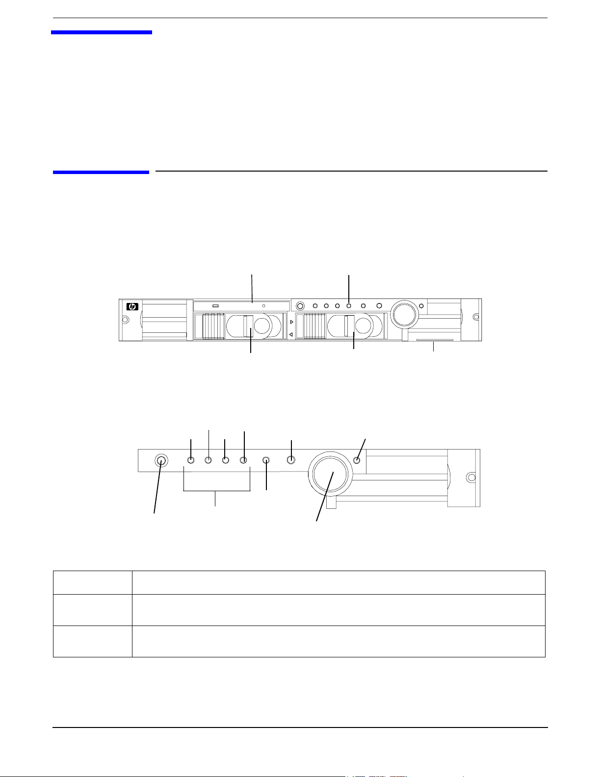
Figure 2-1 Front View
DVD Drive Control Panel
0
1
LVD HDD 2 LVD HDD 1
Figure 2-2 Control Panel
System
LED
LAN
LED
Power On/Off
Button
Locator
Button and
LED
LED 2 LED 4
LED 1 LED 3
Diagnostics
LEDs
Table 2-1 Control Panel LEDs and Switches
Name Function
Power On/Off
LED
Power On/Off
Button
The green on/off LED is illuminated when the power is on.
This is the power on/off switch for the server.
System Product
Label
Power On/Off
LED
Chapter 2
15
Page 16

Controls, Ports and Indicators
Additional Controls and Indicators
Table 2-1 Control Panel LEDs and Switches (Continued)
Name Function
System LED The System LED provides information about the system status. When the system is
running code other than Operating System, the LED is flashing green. When operation
is normal, the LED is green. When there is a system warning, the LED is flashing yellow.
When there is a system fault, the LED is flashing red.
LAN LED The LAN LED provides status information about the LAN interface. When the LAN LED
is flashing, there is activity on the LAN.
a
Diagnostic
LED 1
Diagnostic
LED 2
Diagnostic
LED 3
Diagnostic
LED 4
Locator
Button and
LED
The four diagnostic LEDs operate in conjunction with the system LED to provide
diagnostic information about the system.
a
The four diagnostic LEDs operate in conjunction with the system LED to provide
diagnostic information about the system.
a
The four diagnostic LEDs operate in conjunction with the system LED to provide
diagnostic information about the system.
a
The four diagnostic LEDs operate in conjunction with the system LED to provide
diagnostic information about the system.
a
The locator button and LED are used to help locate this server within a rack of servers.
When the button is engaged, the blue LED illuminates and an additional blue LED on
the rear panel of the server illuminates. This function may be remotely activated.
a. See Chapter 6, Troubleshooting, for details on information provided by the system and diagnostic
LEDs.
Additional Controls and Indicators
The hp Integrity rx1600 Server can have up to two low-voltage differential (LVD), 3.5 inch form factor hard
disk drives installed. These hard disk drives have LEDs that provide status and activity information.
Hard Disk Drive Indicators
The hard disk drives have two LEDs per drive, as described below.
• Activity LED—The Drive Activity LED is green and indicates disk drive activity. This LED is directly
controlled by the disk drive and turns on when a drive is accessed.
16
Chapter 2
Page 17
• Status LED—The Drive Status LED is not used on the hp Integrity rx1600.
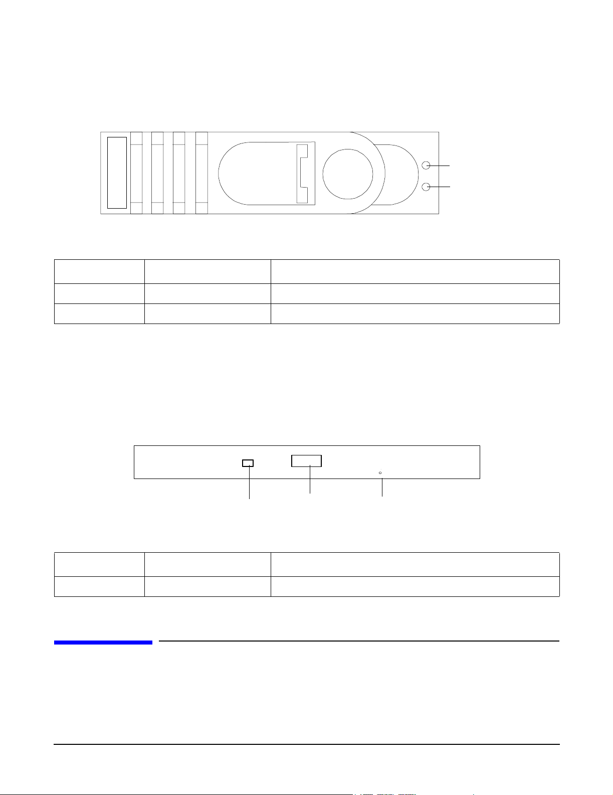
Figure 2-3 Hard Disk Drive LED Indicators
Table 2-2 Hard Disk Drive LED Definitions
LED Activity Description
Activity LED Flashing green Drive access under hard drive control
Status LED None Not Used
Controls, Ports and Indicators
Rear Panel
Activity
LED
Status
LED
Optional Removable Media Drive
The hp Integrity rx1600 Server is delivered without a removable media drive. Either a DVD or CD-RW/DVD
drive may be added. Each of these optional devices has one activity LED.
Figure 2-4 DVD
DVD
Eject ButtonActivity LED
Table 2-3 DVD Drive LED Definitions
LED Description
Activity LED Flashing green Drive activity
Emergency Eject
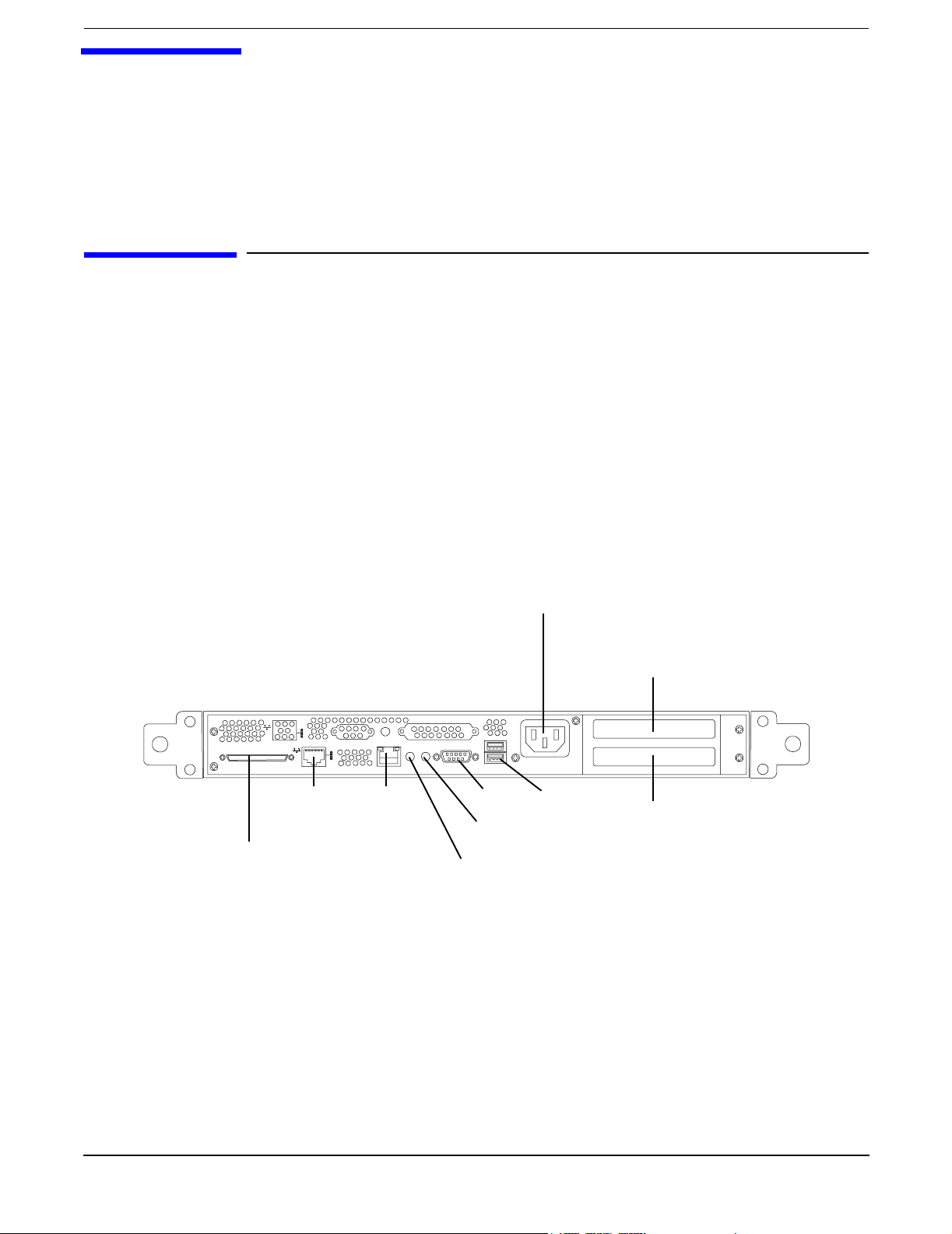
Rear Panel
The hp Integrity rx1600 Server rear panel includes communication ports, I/O ports, AC power connector, and
the locator LED/button. Additional LEDs located on the rear panel of the hp Integrity rx1600 Server signal
the operational status of:
Chapter 2
17
Page 18
Controls, Ports and Indicators
Rear Panel
• Optional Management Processor Card LAN
•PCI Slots 1 and 2
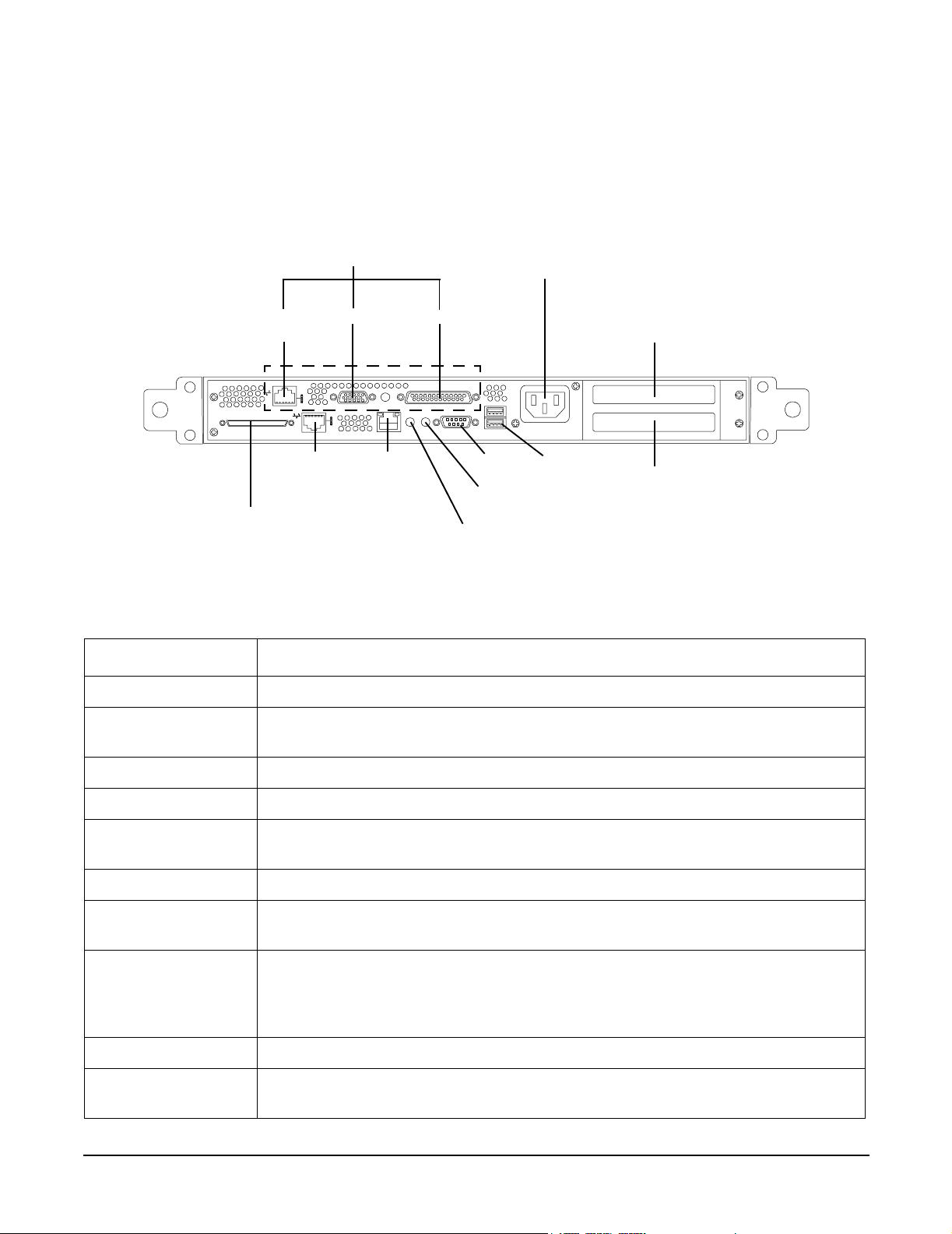
Figure 2-5 Rear View
Optional
Management Board
Connectors
AC Power
Receptacle
10/100
LAN
10/100/1000
LVD/SE SCSI
LAN
Video
10/100
LAN
Serial
Serial
ToC
Locator Button
and LED
USB
PCI Slot 1
PCI Slot 2
Table 2-4 Rear Panel Connectors and Switches
Connector/Switch Function
AC Power Primary power connection for the server
LVD/SE SCSI 68-pin, low-voltage differential, single-ended U320 SCSI. This connector provides
external SCSI connection on SCSI Channel B.
10/100/1000 LAN 10/100/1000 base-T ethernet LAN connector
10/100 LAN 10/100 base-T ethernet LAN connector Wake-on-LAN, Alert-on-LAN capabilities
Serial 9-pin male serial connector — this is the console connector is the optional
management processor card is not installed.
USB Two Universal Serial Bus (USB 2.0) connectors
ToC Transfer of Control button. Halts all system processing and I/O activity and
restarts the computer system.
Locator Button and
LED
The locator button and LED are used to help locate a server within a rack of
servers. When the button is engaged, the blue LED illuminates and an additional
blue LED on the front panel of the server illuminates. This function may be
remotely activated.
Video (optional) 15-pin female video connector for the optional management processor card
Serial (optional) 25-pin female serial data bus connector for the optional management processor
card
18
Chapter 2
Page 19
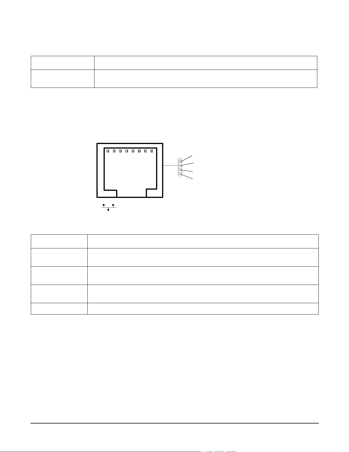
Table 2-4 Rear Panel Connectors and Switches (Continued)
Connector/Switch Function
Controls, Ports and Indicators
Rear Panel
10/100 LAN
(optional)
10 Mb/100 Mb LAN connector for the optional management processor card
10/100/1000 base-T ethernet LAN Connector
The rear panel 10/100/1000 base-T ethernet LAN connector has the following status and activity LEDs.
Figure 2-6 10/100/1000 base-T ethernet LAN Connector LEDs
1000BT
100BT
10BT
Activity
Table 2-5 10/100/1000 base-T ethernet LAN Connector LEDs
LED Description
1000BT Blinking green—the 1000MHz with ethernet protocol and twisted-pair wiring is
enabled, off—no link
100BT Blinking green—the 100MHz with ethernet protocol and twisted-pair wiring is
enabled, off—no link
10BT Blinking green—the 10MHz with ethernet protocol and twisted-pair wiring is
enabled, off—no link
Activity Blinking green—LAN activity
Chapter 2
19
Page 20
Controls, Ports and Indicators
Rear Panel
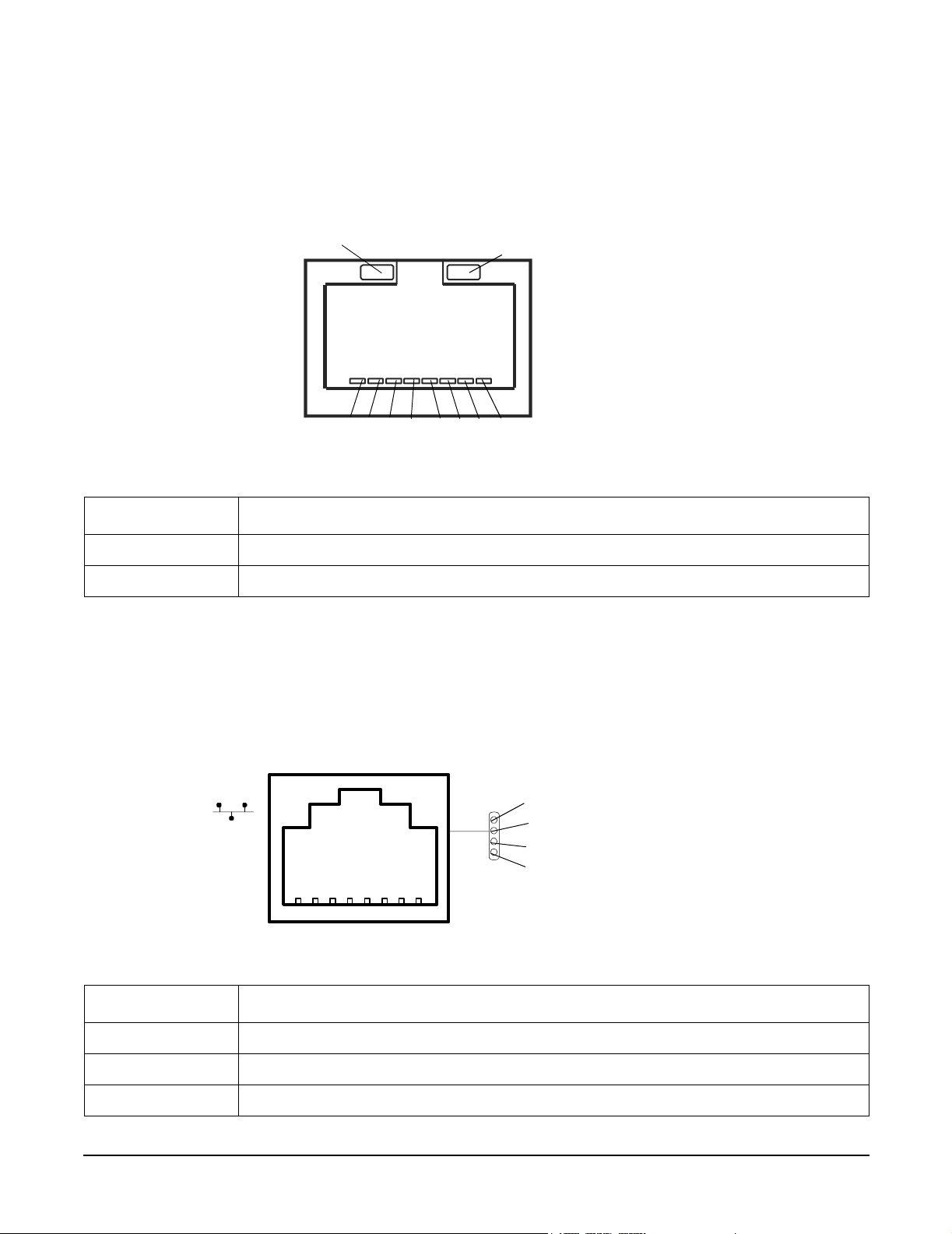
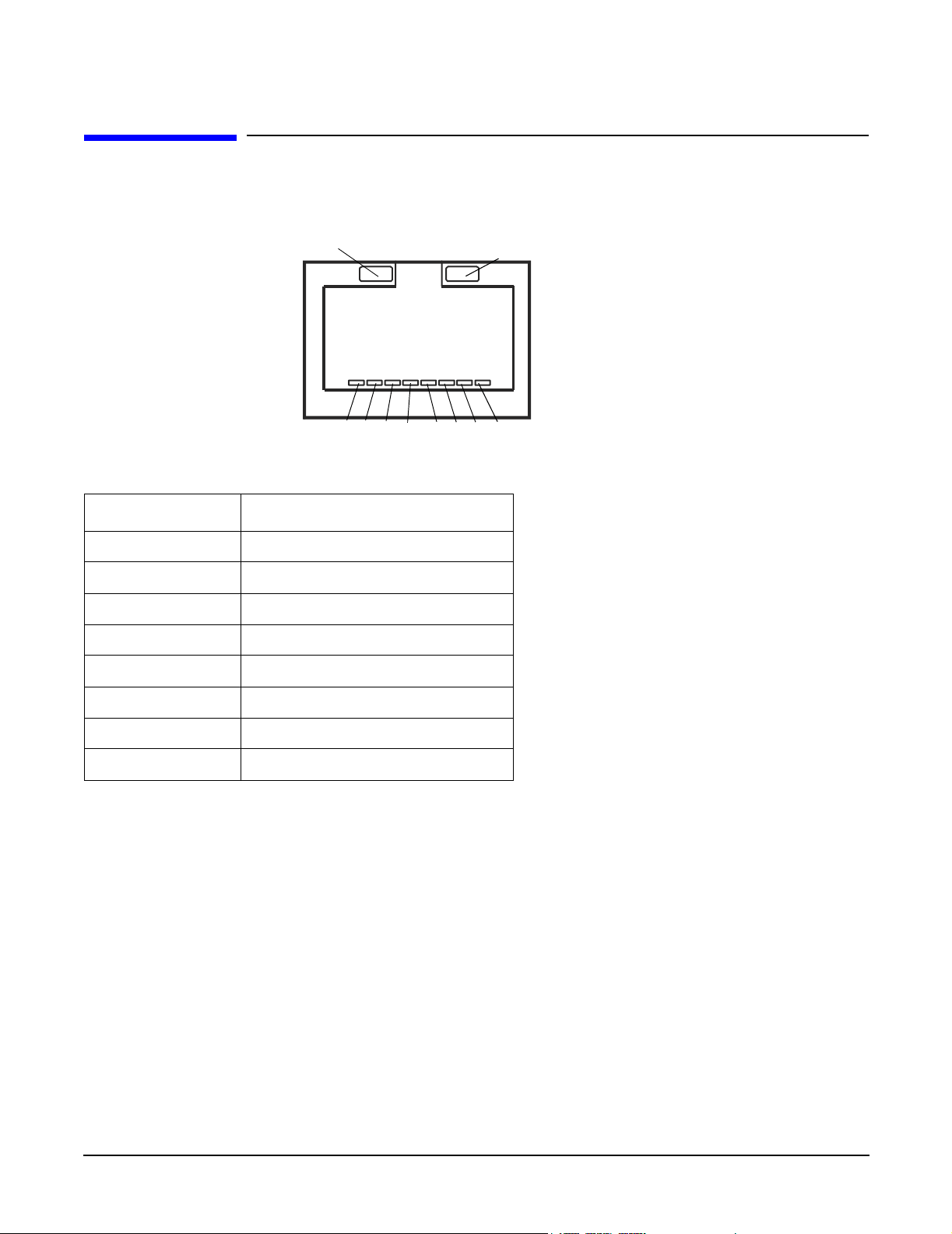
10/100 base-T ethernet LAN Connector
The rear panel 10/100 base-T ethernet LAN connector has the following status and activity LEDs.
Figure 2-7 10/100 base-T ethernet LAN Connector LEDs
Activity (Green)
123 4 567 8
Speed (Yellow)
Table 2-6 10/100 base-T ethernet LAN Connector LEDs
LED Description
Speed (yellow) Off—port linked at 10Mbps, On—port linked at 100Mbps
Activity (green) Off—no link established, On—port linked
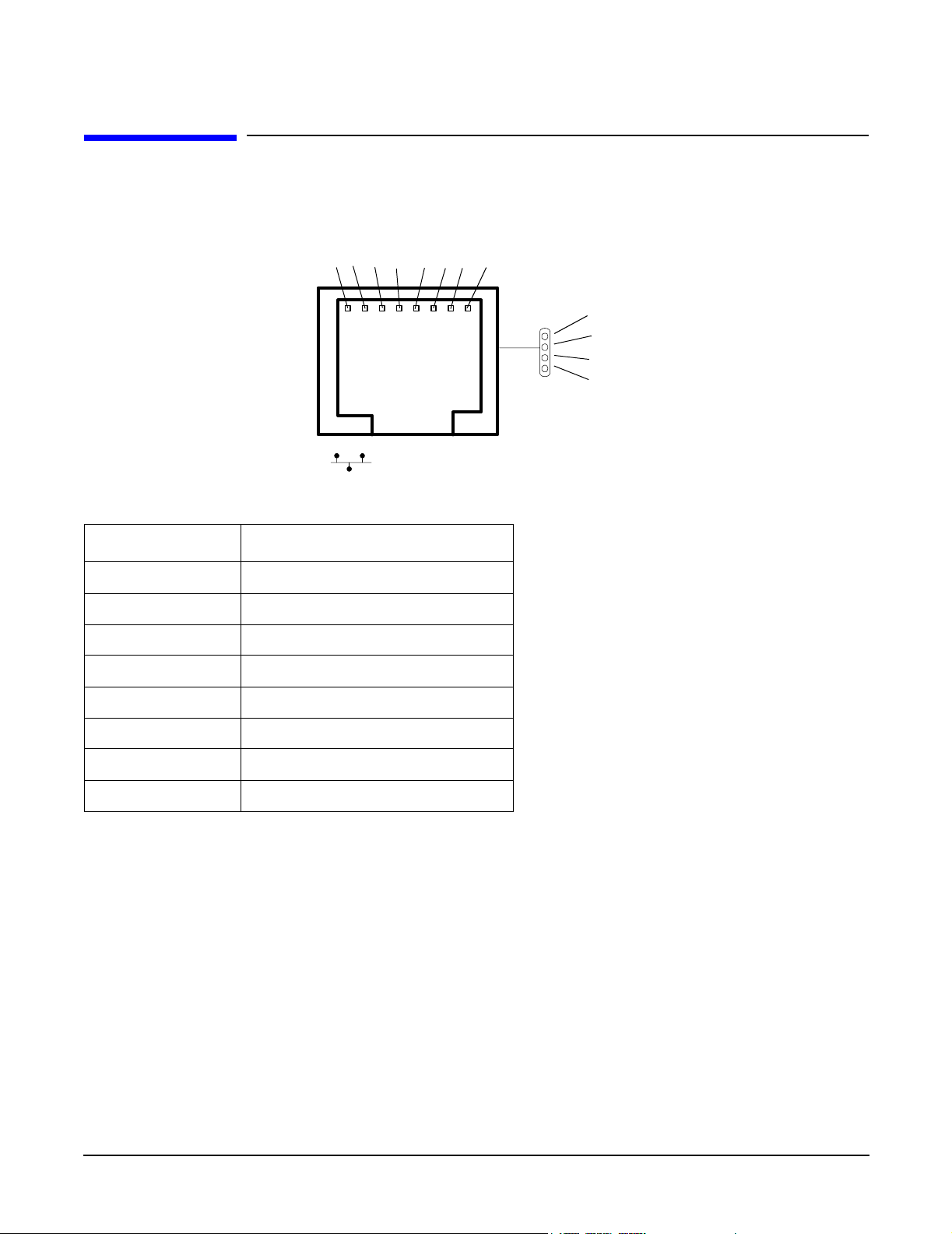
Optional Management Processor Card LAN LEDs
The optional management processor LAN uses an RJ-45 type connector. This connector has four LEDs that
signal status and activity.
Figure 2-8 Optional Management Processor Card LAN LEDs
Self-test
10BT
100BT
Standby power
Table 2-7 Optional Management Processor Card LAN LEDs
LED Description
Self-test Yellow—MP is running self-test or error detected
10BT Green—10BT link established, blinking green—10BT link activity, off—no link
100BT Green—100BT link established, blinking green—100BT link activity, off—no link
20
Chapter 2
Page 21

Controls, Ports and Indicators
Table 2-7 Optional Management Processor Card LAN LEDs (Continued)
LED Description
Standby Power Green—Standby power on, off—standby power off
Rear Panel
Chapter 2
21
Page 22

Controls, Ports and Indicators
Rear Panel
22
Chapter 2
Page 23
3 External Connectors
This chapter describes the external connectors provided on the hp Integrity rx1600 Server.
Connector Pinouts
The following ports and connectors are found on the rear panel of the hp Integrity rx1600 Server.
• Dual USB 2.0
•Serial
• 68-pin LVD, SE U320 SCSI
• 10/100 LAN
• 10/100/1000 LAN
• AC power receptacle
Figure 3-1 Rear View of Server
10/100/1000
LVD/SE SCSI
LAN
10/100
LAN
AC Power
Receptacle
Serial
TOC
Locator Button
and LED
USB
PCI Slot 1
Full size
PCI Slot 2
Half size
Chapter 3
23
Page 24
External Connectors
Universal Serial Bus (USB) Ports
Universal Serial Bus (USB) Ports
Figure 3-2 Dual USB Port Connector
1234
1234
Table 3-1 USB Pi nouts
Pin Number Signal Description
1+5VDC
2MR
3PR
4 Ground
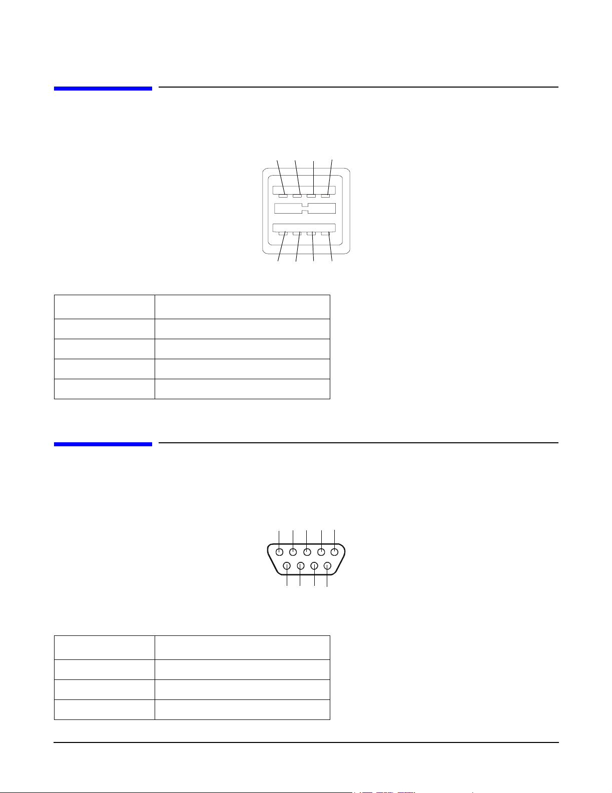
Serial Port
Figure 3-3 Serial Port Connector
12345
6789
Table 3-2 Serial Port Pinouts
Pin Number Signal Description
1 Data Carrier Detect
2 Receive Data
3Transmit Data
24
Chapter 3
Page 25
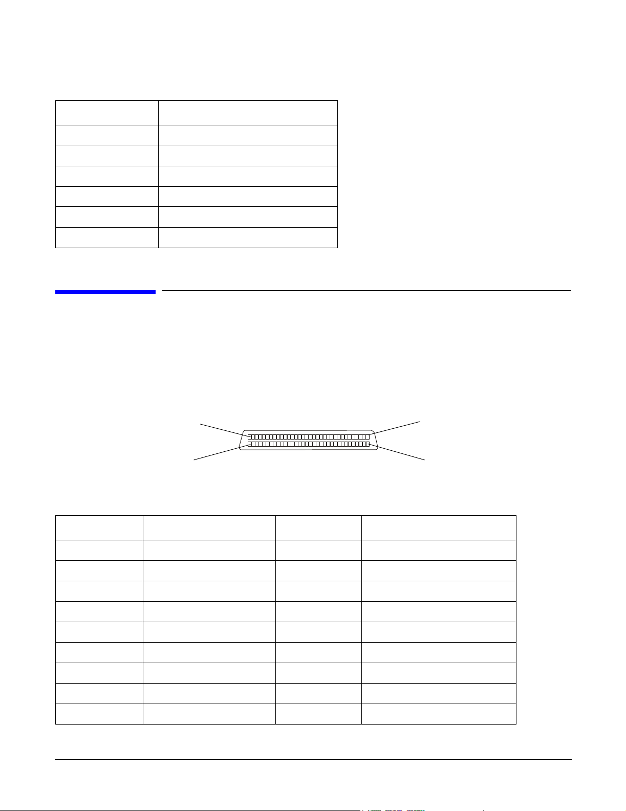
Table 3-2 Serial Port Pinouts (Continued)
Pin Number Signal Description
4 Data Term Ready
5 Ground
6 Data Set Ready
7 Request to Send
8 Clear to Send
9Ring Indicator
SCSI Port, Ultra 3, 68-Pin
External Connectors
SCSI Port, Ultra 3, 68-Pin
A single, Ultra 3, 68 pin SCSI connector is located at the rear panel of the server. The external connector
supports SCSI channel “B.”
Figure 3-4 SCSI Port, Ultra 3, 68-Pin
35
1
68
34
Table 3-3 SCSI Port Pinouts
Pin Number Signal Description Pin Number Signal Description
1 S1 (+DB 12) 35 S35 (-DB 12)
2 S2 (+DB 13) 36 S36 (-DB 13)
3 S3 (+DB 14) 37 S37 (-DB 14)
4 S4 (+DB 15) 38 S38 (-DB 15)
5 S5 (+DB P1) 39 S39 (-DB P1)
6 S6 (+DB 0) 40 S40 (-DB 0)
7 S7 (+DB 1) 41 S41 (-DB 1)
8 S8 (+DB 2) 42 S42 (-DB 2)
9 S9 (DB 3) 43 S43 (-DB 3)
Chapter 3
25
Page 26

External Connectors
SCSI Port, Ultra 3, 68-Pin
Table 3-3 SCSI Port Pinouts (Continued)
Pin Number Signal Description Pin Number Signal Description
10 S10 (+DB 4) 44 S44 (-DB 4)
11 S11 (+DB5) 45 S45 (-DB 5)
12 S12 (+DB 6) 46 S46 (-DB 6)
13 S13 (+DB 7) 47 S47 (-DB 7)
14 S14 (+DB P) 48 S48 (-DB P)
15 S15 49 S49
16 S16 (DIFFSENS) 50 S50
17 S17 (TERMPWR) 51 S51 (TERMPWR)
18 S18 (TERMPWR) 52 S52 (TERMPWR)
19 S19 (RESERVED) 53 S53 (RESERVED)
20 S20 54 S54
21 S21 (+ATN) 55 S55 (-ATN)
22 S22 56 S56
23 S23 (+BSY) 57 S57 (-BSY)
24 S24 (+ACK) 58 S58 (-ACK)
25 S25 (+RST) 59 S59 (-RST)
26 S26 (+MSG) 60 S60 (-MSG)
27 S27 (+SEL) 61 S61 (-SEL)
28 S28 (+C/D) 62 S62 (-C/D)
29 S29 (+REQ) 63 S63 (-REQ)
30 S30 (+I/O) 64 S64 (-I/O)
31 S31 (+DB 8) 65 S65 (-DB 8)
32 S32 (+DB 9) 66 S66 (-DB 9)
33 S33 (DB 10) 67 S67 (-DB 10)
34 S34 (DB 11) 68 S68 (-DB 11)
26
Chapter 3
Page 27
10/100 LAN Connector
Figure 3-5 10/100 LAN Connector
External Connectors
10/100 LAN Connector
Activity (Green)
123 4 567 8
Table 3-4 10/100 LAN Connector Pinouts
Pin Number Signal Description
1TXP
2TXN
3RXP
4Not used
5Not used
Speed (Amber)
6RXN
7Not used
8Not used
Chapter 3
27
Page 28
External Connectors
10/100/1000 LAN Connector
10/100/1000 LAN Connector
Figure 3-6 10/100/1000 LAN Connector
123 4 567 8
Table 3-5 10/100/1000 LAN Connector Pinouts
1000BT
100BT
10BT
Activity
Pin Number Signal Description
1TXP
2TXN
3RXP
4Not used
5Not used
6RXN
7Not used
8Not used
28
Chapter 3
Page 29

4 Installing and Configuring
This chapter provides information required in installing additional components and configuring the hp
Integrity rx1600 Server.
Service Tools Required
Service of this product may require one or more of the following tools:
• IPF CPU Install Tool Kit (P/N 5069-5441), consisting of:
• Disposable ESD Kit
• Label-less CPU install tool (P/N 09901-04007)
• 1/4 inch Flat Blade Screwdriver
• ACX-10 Torx Screwdriver
• ACX-15 Torx Screwdriver
• ACX-25 Torx Screwdriver
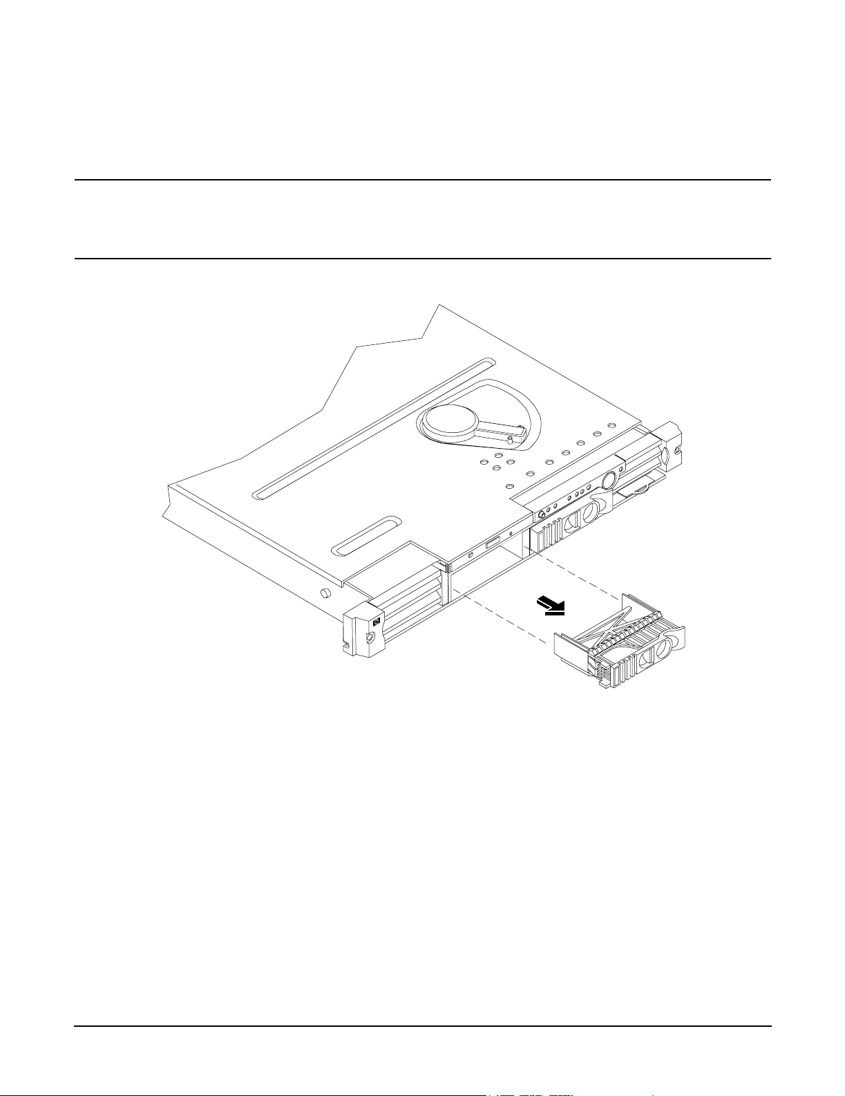
Installing Internal Hard Disk Drives
This section provides information about installing internal hard disk drives.
CAUTION A hot-plug device may require interaction with the operating system before the device can be
safely installed into the server. Verify that the operating system supports installing disk drives
while the operating system is running. If the operating system does not support this feature,
shut down the operating system before attempting this procedure. Failure to observe this
caution will result in system failure.
Figure 4-1 Front View of the hp Integrity rx1600 Server
0
1
LVD HDD 2
Slot 1
One additional hard disk drive may be added to your HP Server in slot 1. Always use low profile disk drives
(1.0” height) in your hp Integrity rx1600.
Chapter 4
LVD HDD 1
Slot 0
29
Page 30
Installing and Configuring
Installing Internal Hard Disk Drives
To install an additional hard disk drive, perform the following steps:
Step 1. Remove the slot filler that is installed in slot 1.
CAUTION If the HP Server is to be operated with only a single hard disk drive installed, the
hard disk drive slot filler must be installed to insure proper cooling. If a hard disk
drive is installed in slot 1, retain the slot filler to be reinstalled if the drive is
removed.
Figure 4-2Filler Removal from Slot 1
Step 2. Slide the hard disk drive into slot 1 until it is seated.
30
Chapter 4
Page 31

Installing and Configuring
Installing Processors and Memory
CAUTION When sliding the hard disk drive into the slot, be careful not to damage the EMI
shielding of the drive. The drive should fit into the slot without excessive use of
pressure.
Figure 4-3Disk Drive Installation in Slot 1
Step 3. Close the drive-ejector handle by pushing it down until it clicks.
Step 4. The hard disk drive is now correctly installed.
Step 5. Validate the hard disk drive installation by:
a. If the server does not have a management processor installed, at the EFI shell prompt input
shell> info io to interrogate the system for proper identification of the drive.
b. If the server has a management processor installed, use the management processor command
MP> sl e to display the system system event log and examine for proper identification of the
drive.
Installing Processors and Memory
This section provides information about installing processors and memory. The processors and memory slots
are located on the system board, which is accessible by removing the system cover.
Chapter 4
31
Page 32

Installing and Configuring
Installing Processors and Memory
WARNING Voltages are present at various locations within the server whenever an AC power
source is connected. This voltage is present even when the main power switch is in
the off position.
Ensure that the system is powered-down and all power sources have been
disconnected from the server prior to attempting the following procedures.
Failure to observe this warning could result in personal injury or damage to
equipment.
CAUTION Do not operate the server without the cover in place. Operation of the server without the cover
in place may result in server failure. Operation of the server without the cover in place will
make the server susceptible to EMI problems.
Observe all ESD safety precautions before attempting this procedure. Failure to follow ESD
safety precautions could result in damage to the server.
Avoid contact with the processor heatsink if the server has been operating prior to the
installation of the additional processor. The heatsink will be safe to touch after the cover has
been removed for a few seconds.
Installing an Additional Processor
CAUTION Ensure that the cache size is identical for all processors. Failure to observe this caution will
result in system failure.
Ensure that all processors are rated for use at the same speed. Failure to observe this caution
will result in performance degradation.
Valid processors are identified in Chapter 8, “Parts Information.”
Processor Load Order
Processors are located on the system board. The system board can support either one or two processors. CPU
0 is located to the right of the system board and CPU 1 (when installed) is located on the left of the system
board next to the bridge assembly. In a single CPU configuration, the single processor must be installed in
CPU 0 slot.
32
Chapter 4
Page 33

Each processor has an associated power pod that is required by the processor.
Figure 4-4 Processor Location
POWER POD
CPU 1
Rear of Chassis
POWER POD
CPU 0
CPU 0
Installing and Configuring
Installing Processors and Memory
CPU 1
Step 1. Remove the cover. See Removing and Replacing the Cover.
Step 2. If CPU airflow blocker is installed, remove the airflow blocker.
Front of Chassis
Chapter 4
33
Page 34

Installing and Configuring
Installing Processors and Memory
CAUTION If the HP Server is to be operated with only a single processor installed, the CPU
airflow blocker must be installed to insure proper cooling. If a second processor is
installed in location CPU 1, retain the airflow blocker to be reinstalled if the
processor is removed.
Figure 4-5Removing the Airflow Blocker
Step 3. Unlock the processor-locking mechanism using the special processor tool (P/N 5069-5441), or
equivalent 2.5 mm hex tool, shipped with your replacement processor assembly. Insert the tool into
the lock and rotate the special processor tool 180 degrees counterclockwise. Verify that the
processor-locking mechanism is rotated into the unlocked position.
34
Chapter 4
Page 35

Installing and Configuring
Installing Processors and Memory
CAUTION The zero insertion force (ZIF) socket for the processor is locked and unlocked by 1/2 of
a full turn of the 2.5 mm hex tool. The counterclockwise 180 degree rotation (1/2
turn) unlocks the socket. A clockwise 180 degree rotation locks the socket.
Attempting to turn the locking mechanism more that 180 degrees can severely
damage the socket.
Figure 4-6Unlocking the Processor Locking Mechanism
Unlocked
Locked
Front of server
Chapter 4
35
Page 36

Installing and Configuring
Installing Processors and Memory
Step 4. Place the processor and heatsink assembly over the processor socket. Use the four locator posts on
the assembly to align with the locator holes on the system board. Make certain that the connector
that will mate with the processor power pod is pointing toward the back of the chassis.
Figure 4-7Aligning the Processor Assembly
Note: When properly
aligned, the connector of
the processor and heatsink
assembly will face the rear
of the chassis.
Front of server
Step 5. Use the special processor tool (P/N 5069-5441) shipped with your replacement processor assembly
to lock the processor in place on the system board. To do this, insert the special processor tool into
the lock and rotate it clockwise 180 degrees.
Figure 4-8Locking the Processor Assembly in Place
Unlocked
Locked
36
Front of server
Chapter 4
Page 37

Installing Processors and Memory
Step 6. Remove the protective caps from the screws on the sequencer retaining cover.
Step 7. Place the sequencer retaining cover over the top of the heatsink.
Figure 4-9Installing the Sequencer Retaining Cover
Protective caps
Installing and Configuring
Step 8. Screw in the four sequencer captive screws.
Figure 4-10Securing the Sequencer Retaining Cover
4
1
3
Front of server
Torquing pattern
1
3
2
Front of server
4
2
Chapter 4
37
Page 38

Installing and Configuring
Installing Processors and Memory
Step 9. Slide the power module on the system board metal mounting bracket forward to mate the power
module connector with the processor connector.
Figure 4-11Connecting the Processor Power Pod
Front of server
Step 10. Align the two mounting screw holes on the power module with their screw holes on the system
board’s metal mounting bracket. Screw in the power module mounting screws.
Figure 4-12Securing the Processor Power Pod
Front of server
38
Chapter 4
Page 39

Step 11. Connect the power pod cable to the power connector on the system board.
Figure 4-13Connecting the Power Cable
Front of server
Installing and Configuring
Installing Additional Memory
Step 12. Replace the cover.
Step 13. Verify that the newly installed processor works:
•Run the info cpu command at the EFI shell prompt, or
•Run cpu diag from Offline Diagnostic CD for full functional check.
Installing Additional Memory
The hp Integrity rx1600 Server has 8 memory sockets for installing DDR SDRAM memory modules. These
memory modules can either be 256MB, 512MB, 1GB, or 2GB size. The system supports combinations from
512 MB up to 16GB.
Supported DIMM sizes
Supported DIMM sizes are 256MB, 512MB, 1GB, 2GB. Dissimilar DIMM sizes may be used in any available
slot pairs but all DIMMs in each pair must match.
Paired DIMM slots are:
• Pair 1 = DIMM Slot 0A and 0B
• Pair 2 = DIMM Slot 1A and 1B
• Pair 3 = DIMM Slot 2A and 2B
Chapter 4
39
Page 40

Installing and Configuring
Installing Additional Memory
• Pair 4 = DIMM Slot 3A and 3B
Figure 4-14 DIMM Loading Order
Rear
Pair 4
Pair 2
1A
1B
3A
3B
2A
0A
2B
0B
Front
Pair 3
Pair 1
DIMM Locations
Eight DIMM slots are provided on the system board. These DIMM slots are designated in ordered pairs. 0A
and 0B, 1A and 1B, 2A and 2B, and 3A and 3B. DIMM sizes within each pair must match. Loading order for
the DIMM slots is sequential with the loading order being slot 0, slot 1, slot 2 and slot 3.
The memory subsystem supports chip spare functionality. Chip spare enables an entire SDRAM chip on a
DIMM to be bypassed (logically replaced) in the event that a multi-bit error is detected on that SDRAM.
In order to use the chip spare functionality, only DIMMs built with x4 SDRAM parts can be used, and these
DIMMs must be loaded in quads (2 DIMMs per memory cell, loaded in the same location in each memory cell).
40
Chapter 4
Page 41

Each DIMM within a quad must be identical to all the other DIMMs in the quad.
Figure 4-15 DIMM Locations
DIMM
Slot 1B
DIMM
Slot 3B
DIMM
Slot 1A
DIMM
Slot 3A
Installing and Configuring
Installing Additional Memory
DIMM
Slot 0B
DIMM
Slot 2B
DIMM
Slot 0A
DIMM
Slot 2A
Installing DIMMs
To install DIMMs, perform the following steps:
Step 1. Turn off the system, disconnect all cables, and remove the system cover.
Chapter 4
41
Page 42

Installing and Configuring
Installing Additional Memory
CAUTION To ensure that memory modules are not damaged during removal or installation,
power off the server and unplug the power cord from the AC power outlet. Wait until
the power on/off LED on the control panel turns off before removing or installing
memory.
Observe all ESD safety precautions before attempting this procedure. Failure to
follow ESD safety precautions could result in damage to the server.
Step 2. Determine the memory slot location to be used for the DIMM(s) being installed. See “DIMM
Locations”.
Step 3. Insure that the latches of the DIMM socket are in the open (outward) position.
Step 4. Align the DIMM with the socket located on the system board.
NOTE The DIMMs and the DIMM sockets are keyed to prevent improper insertion of the
modules.
Step 5. Gently and evenly push down on the top edge of the DIMM until it seats in the socket. Ensure the
extraction levers are in the closed position.
CAUTION Avoid applying too much pressure to the DIMM when inserting the module into the
socket. It is possible to damage the socket connector. Touch only the outer card edge
of the module.
Figure 4-16Inserting DIMM into Memory Slot
Step 6. Replace the cover, reconnect all cables, and turn on the power.
Step 7. Verify that the newly installed memory works:
42
Chapter 4
Page 43

Installing and Configuring
Installing Additional PCI Cards
•Run the info mem command at the EFI shell prompt, or
•Run memdiag from the Offline Diagnostics DC to insure that the memory is functional.
Installing Additional PCI Cards
The server may contain up to 2 PCI cards. PCI cards are located on the I/O riser assembly.
WARNING Ensure that the system is powered-down and all power sources have been
disconnected from the server prior to removing or replacing a PCI card.
Voltages are present at various locations within the server whenever an AC power
source is connected. This voltage is present even when the main power switch is in
the off position.
Failure to observe this warning could result in personal injury or damage to
equipment.
CAUTION Observe all ESD safety precautions before attempting this procedure. Failure to follow ESD
safety precautions could result in damage to the server.
Carefully read the following information concerning PCI slot configuration. Inserting a PCI card into a slot
that is not configured to accept it may cause operation failure or the PCI card to operate at less than optimum
speed. PCI slots are numbered 1 and 2. See the labels on the rear panel of the chassis for correct PCI slot
number identification.
The following describes configuration requirements for slots 1 through 2:
• Slot 1(top) is a single, full size PCI slot that runs at 133MHz.
• Slot 2 (bottom) is a single, half-size PCI slot that runs at 133MHz.
Installing a PCI Card
To install a PCI card in the server, perform the following steps:
CAUTION Record the location of all PCI cards as they are installed. Depending on the operating system,
replacing the PCI card in a different location might cause boot failure.
Step 1. Remove the cover. See Removing and Replacing the Cover.
Chapter 4
43
Page 44

Installing and Configuring
Installing Additional PCI Cards
Step 2. Release the PCI I/O riser by turning the jackscrew. This action frees the PCI I/O riser from the
system board.
Figure 4-17 Using Jackscrew to Release PCI I/O Riser
Step 3. Remove the PCI I/O Riser from the chassis.
Figure 4-18Removing the PCI I/O Riser Assembly
44
Chapter 4
Page 45

Installing and Configuring
Installing Additional PCI Cards
Step 4. Remove the PCI slot cover.
Figure 4-19Removing a PCI Slot Cover
Step 5. Grasp the edges of the PCI card being installed and gently press the connector into the PCI I/O
riser connector.
NOTE Full length PCI cards may only be installed in slot 1, the top slot of the PCI I/O riser
assembly. The lower slot (slot 2) can only accept half length cards.
Figure 4-20Installing a PCI Card
Step 6. Insert the card mounting screw and secure with a T-15 driver.
Step 7. Replace the PCI I/O riser assembly by positioning the connector over the mating connector on the
system board and then turning the jackscrew to complete the connector mating.
Step 8. Connect any cables that are required by the PCI card.
Step 9. Replace the cover. See Removing and Replacing the Cover.
Chapter 4
45
Page 46

Installing and Configuring
Optional Management Processor Card (MP)
Optional Management Processor Card (MP)
The management processor is an independent support system for the server. It provides a way for you to
connect to a server and perform administration or monitoring tasks for the server hardware.
The management processor controls power, reset, transfer of control (TOC) capabilities, provides console
access, displays and records system events, and can display detailed information about the various internal
subsystems. The management processor also provides a virtual front panel which can be used to monitor the
front panel LEDs from a remote location.
The management processor is available whenever the system is connected to a power source, even if the hp
Integrity rx1600 Server main power switch is in the off position.
Access to the management processor can be restricted by user accounts. User accounts can be password
protected and provide a specific level of access to the server and management processor commands.
Multiple users can interact with the management processor. However, all output is mirrored. The
management processor Main Menu permits all users to interact and mirrors output to all users. The console
permits one interactive user at a time and mirrors output to all users accessing those features.
Step 1. Turn off the system, disconnect all power and external cables and remove the system cover(s).
Step 2. If you are installing a new card, remove the MP card blank.
Step 3. Unscrew the mounting screw for the MP card blank, located on the external connector side of the
system chassis.
Step 4. Remove the blank retaining tab out of its socket on the system chassis and remove the blank from
the system.
Figure 4-21Removing the MP Card Blank
Step 5. Remove the insulator between the battery and the battery socket on the management processor
card.
Step 6. Align the MP card over the two mounting posts on the system board and align the three connectors
of the MP card with the cutouts on the rear panel.
46
Chapter 4
Page 47

Installing and Configuring
Optional Management Processor Card (MP)
Step 7. Carefully push the 10/100 Management LAN, 15-pin VGA and 25-pin serial connectors through
their openings on the rear panel.
CAUTION Special care should be used when mating the connectors of the MP card with the
sheet metal of the rear panel. It is possible to damage the EMI gasket of the RJ-45 of
the card.
Step 8. Connect the MP card cable to its connector on the system board.
Step 9. Screw in the two mounting screws that connect the MP card to the internal chassis post.
Figure 4-22Connecting the Management Processor Card
Chapter 4
47
Page 48

Installing and Configuring
Optional Management Processor Card (MP)
Step 10. Screw in the two external mounting posts that are located on both sides of the 25-pin serial
connector.
Figure 4-23Installing the External Mounting Posts
Step 11. Replace the system cover and reconnect the power and external cables.
Information required to access, configure and to utilize the management processor is provided in Chapter 5,
“Utilities.”.
48
Chapter 4
Page 49

5 Utilities
Extensible Firmware Interface (EFI) Boot Manager
EFI (Extensible Firmware Interface) is an OS and platform-independent boot and pre-boot interface. EFI lies
between the OS and platform firmware, allowing the OS to boot without having details about the underlying
hardware and firmware. EFI supports boot devices; uses a flat memory model; and hides platform and
firmware details from the OS.
NOTE EFI and Pre-OS System Environment (POSSE) are similar. EFI is an Intel® specification,
whereas POSSE is the HP implementation that aids HP support.
EFI consolidates boot utilities similar to those found in PA-RISC based systems, such as the Boot Console
Handler (BCH), and platform firmware into a single platform firmware. EFI allows the selection of any EFI
OS loader from any boot medium that is supported by EFI boot services. An EFI OS loader supports multiple
options on the user interface.
EFI supports booting from media that contain an EFI OS loader or an EFI-defined system partition. An
EFI-defined system partition is required by EFI to boot from a block device.
Figure 5-1 EFI Boot Sequence
EFI
Platform
Init
Standard
firmware
platform
initialization
Driver
EFI Image
Load
Drivers and
application
loaded
iteratively
Application
Application Program
Interface (API) specified
EFI
EFI
Bootcode
Retry
Failure
EFI
OS Loader
Load
Boot from
ordered list
of EFI OS
loaders
Value add implementation
OS Loader
EFI API
Boot Services
Ter minate
Operation
handed off to
OS Loader
Chapter 5
Boot manager EFI transfers
49
Page 50

Utilities
Extensible Firmware Interface (EFI) Boot Manager
The EFI boot manager loads EFI applications (including operating system [OS] first stage loader) and EFI
drivers from an EFI-defined file system or image loading service. Non-volatile RAM (NVRAM) variables point
to the file to be loaded. These variables contain application-specific data that is passed directly to the EFI
application. EFI variables provides system firmware a boot menu that points to all the operating systems,
even multiple versions of the same operating systems.
The EFI boot manager allows you to control the server’s booting environment. Depending on how you have
configured the boot options, after the server is powered up the boot manager presents you with different ways
to bring up the system. For example, you can boot to the EFI shell, to an operating system located on the
network or residing on media in the server, or the Boot Maintenance menu, see “Using the Boot Option
Maintenance Menu”.
• Boot from a File—Automatically adds EFI applications as boot options or allows you to boot from a
specific file. When you choose this option, the system searches for an EFI directory. If the EFI directory is
found, then it looks in each of the subdirectories below EFI. In each of those subdirectories, it looks for the
first file that is an executable EFI application. Each of the EFI applications that meet this criterion can
be automatically added as a boot option. In addition, legacy boot options for A: and C: are also added if
those devices are present. You can also launch a specific application without adding it as a boot option. In
this case the EFI boot manager searches the root directories and the \EFI\TOOLS directories of all of the
EFI system partitions present in the system for the specified EFI application.
• Add a Boot Option—Adds a boot option to the EFI boot manager. You specify the option by providing the
name of the EFI application. Along with the name you can also provide either ASCII or UNICODE
arguments the file might use. Given the EFI application name and any options, the EFI boot manager
searches for the executable file in the same directories as described in “Boot from a File” option. When the
file is found, it is executed.
• Delete Boot Options—Deletes a specific boot option or all boot options.
• Change Boot Order—Controls the relative order in which the EFI boot manager attempts boot options.
For help on the control key sequences you need for this option, refer to the help menu.
• Manage BootNext Setting—Selects a boot option to use one time (the next boot operation).
• Set Automatic Boot Timeout—Defines the value in seconds that pass before the system automatically
boots without user intervention. Setting this value to zero disables the timeout feature.
• Exit—Returns control to the EFI boot manager main menu. This displays the active boot devices,
including a possible integrated shell (if the implementation is so constructed).
50
Chapter 5
Page 51

Utilities
Extensible Firmware Interface (EFI) Boot Manager
EFI Commands
Table 5-1 lists EFI commands for the hp Integrity rx1600 Server. The equivalent BCH commands found in
PA-RISC based systems are also listed.
Table 5-1 EFI C omma n ds
BCH
EFI Shell
Command
These commands are found in all other menus
info boot Boot [PRI|HAA|ALT|<path>] Boot from specified path
help <command> HElp [<menu>|<command>] Display help for specified
reset RESET Reset the system (to
Command
Equivalent
(PA-RISC)
BCH Command Parameters
(PA-RISC)
Definition
command or menu
allow reconfiguration of
complex
exit (at EFI shell) MAin Return to the main menu
MAin
EFI boot manager
“change boot
order”
bcfg SEArch [ALL] Search for boot devices
bcfg SEArch [DIsplay|IPL] [<path>] Search for boot devices
many commands
offer a [-b]
parameter to cause
25 line breaks
COnfiguration
autoboot AUto [BOot|SEarch|STart] [ON|OFF] Display or set the auto
info boot BootID [<processor #>[<bootid #>]] Display or set processor
EFI boot manager Boot info Display boot-related
PAth [PRI|HAA|ALT|CON|KEY|<path>] Display or modify a path
ScRoll [ON|OFF] Display or change
scrolling capability
start flag
boot identifier
information
autoboot BootTimer [0-200] Seconds allowed for boot
attempt
cpuconfig CPUconfig [<proc>][ON|OFF]] Config/deconfig processor
boottest FastBoot [ON|OFF] or [test] [RUN|SKIP] Display or set boot tests
execution
Chapter 5
51
Page 52

Utilities
Extensible Firmware Interface (EFI) Boot Manager
Table 5-1 EFI Commands (Continued)
BCH
EFI Shell
Command
date Time [cn:yr:mo:dy:hr:mn[:ss]] Read or set the date
time Time [cn:yr:mo:dy:hr:mn[:ss]] Read or set the real time
INformation
info all ALL Display all system
info boot BootINfo Display boot-releated
info cpu CAche Display cache
Command
Equivalent
(PA-RISC)
BCH Command Parameters
(PA-RISC)
Definition
clock
information
information
information
info chiprev ChipRevisions Display revision number
of major VLSI
MP command <df> FRU Display FRU information
info fw FwrVersion Display firmware version
for PDC, ICM, and
complex
info io IO Display firmware version
for PDC, ICM, and
complex
lanaddress LanAddress Display core LAN station
address
info mem Memory Display memory
information
info cpu PRocessor Display processor
information
SERvice
errdump clear CLEARPIM Clear (zero) the contents
of PIM
mm MemRead <addr> [<len>] [<type>] Read memory locations
scope of page
deallocation
pdt page
deallocation
table (pdt)
52
Display or clear the page
deallocation table
Chapter 5
Page 53

Table 5-1 EFI Commands (Continued)
BCH
EFI Shell
Command
Command
Equivalent
(PA-RISC)
BCH Command Parameters
(PA-RISC)
Utilities
EFI/POSSE Commands
Definition
errdump mca
errdump cmc
errdump init
processor
internal
memory (PIM)
[<proc>] [HPMC|LPMC|TOC|ASIC]] Display PIM information
EFI/POSSE Commands
This section describes the EFI/POSSE commands developed for the server.
NOTE EFI and Pre-OS System Environment (POSSE) are similar. EFI is an Intel specification,
whereas POSSE is the HP implementation that aids HP support.
help
Provides information on the EFI shell commands. It also has an additional feature to aid those familiar with
the BCH menus to adjust to their equivalent functions in EFI.
Syntax
help [-b] <category>
help [-b] <cmd>
help [-b] bch <bchmenu> <bchcmd>
Par am eters
-b Enable page breaking
category Category of commands to view help on commands
cmd Shell command name on which to provide verbose information
bch Display the list of BCH commands and their corresponding EFI
bchmenu BCH menu name taken from the top level of the BCH menu
bchcmd BCH command on which to display information
Operation
If help is invoked with no parameters, it displays a list of shell command categories. To list all of the
commands within a category, the user should type help <category> (see examples). If invoked with the -b
switch, any output longer than one page pauses after each page is displayed. If a shell command name is used
as a parameter, verbose help is displayed for that command.
If help is invoked with the bch option, it displays a list of BCH commands and their corresponding
EFI/POSSE commands. It instructs the user to repeat the command line followed by a menu name for more
information on that menu. If help is invoked followed by bch and a menu name, it displays a list of commands
that appear under that BCH menu. The user may then invoke help followed by bch, the menu name, and a
BCH command name to display information on that command. This would point the user to the command
Chapter 5
53
Page 54

Utilities
EFI/POSSE Commands
that has taken the place of that BCH functionality, or will inform the user that the functionality no longer
exists. As a shortcut, the user may enter help followed by bch and a BCH command name to go straight to
that command.
Example 5-1 help Command
Shell> help
List of classes of commands:
boot -- Booting options and disk-related commands
configuration -- Changing and retrieving system information
devices -- Getting device, driver and handle information
memory -- Memory related commands
shell -- Basic shell navigation and customization
scripts -- EFI shell-script commandsType "help" followed by a class name for a list of commands in
that class
Type "help" followed by command name for full documentation
Example 5-2 help bch Command
COnfiguration help bch co
INformation help bch in
PAth help bch pa
ScRool help bch sr
SEArch help bch sea
SERvice help bch ser
BOot help bch bo
HElp help bch he
RESET help bch reset
MAin help bch ma
For more help on one of the commands above, at the prompt type:
help bch COMMAND
Example 5-3 help configuration Command
Shell> help configuration
Configuration commands:
cpuconfig -- Deconfigure or reconfigure cpus
date -- Display or set date
err -- Display or set error level
esiproc -- Make an ESI call
errdump -- View/Clear logs
info -- Display hardware information
monarch -- View or set the monarch processor
palproc -- Make a PAL call
salproc -- Make a SAL call
time -- Display or set time
ver -- Displays version info
Type "help" followed by command name for full documentationon that command.
Type "help -a" to display a list of all commands.
Example 5-4 help cpuconfig Command
Shell> help cpuconfig
CPUCONFIG [cpu] [on|off]
cpu Specifies which cpu to configure
on|off Specifies to configure or deconfigure a cpu
54
Chapter 5
Page 55

Notes:
1. Cpu status will not change until next boot
Examples:
* To deconfigure CPU 0
fs0:\> cpuconfig 0 off
CPU will be deconfigured on the next boot
* To display configuration status of cpus
fs0:\> cpuconfig
<CPU configuration data displayed>
baud
Sets the baud rate and communication settings for a UART.
Syntax
baud <index> <baudrate>
Par am eters
<index> 0 through the total number of UARTS minus one
<baudrate> baud rate.
Utilities
EFI/POSSE Commands
Operation
This command is used to change the speed for a UART in the system. This command works for all UARTs
visible to EFI/POSSE. If the UART is part of processor dependent hardware (PDH) space and is initialized by
the core firmware, this command communicates the settings to core firmware so the UART can be initialized
with the new settings on the next boot. System default is 9600 baud.
Other Communication parameters are listed in Table 5-2.
Table 5-2 Communications Parameters
Parameter Val ue
RECEIVE_FIFO_DEPTH 1
TIMEOUT 1000000
PARITY No parity
DATA_BITS 8
STOP_BITS 1
CONTROL_MASK 0
boottest
Interacts with the speedy boot variable allowing it to be set appropriately.
Chapter 5
55
Page 56

Utilities
EFI/POSSE Commands
Syntax
boottest Displays status of all speedy boot bits
boottest on Run all tests (for a normal boot time)
boottest off Skip all tests (for a faster boot time)
boottest [test] Displays status of specific Speedy Boot bit
boottest [test] [on|off] Sets or clears a specific Speedy Boot bit
Par am eters
[test] Each test can be set or cleared:
booting_valid Enable/disable system firmware response to BOOTING
early_cpu Enable/disable early CPU selftests.
late_cpu Enable/disable late CPU selftests.
platform Enable/disable system board hardware tests.
chipset Enable/disable CEC tests.
io_hw Enable/disable EFI driver Core I/O tests.
mem_init Enable/disable memory initialization.
mem_test Enable/disable full destructive memory tests.
bit. If OS Speedy Boot aware set to on.
Example 5-5 boottest Command
Shell> boottest
BOOTTEST Settings Default Variable
Selftest Setting
------------- ------------------------booting_valid On (OS speedy boot aware)
early_cpu Run this test
late_cpu Run this test
platform Run this test
chipset Run this test
io_hw Run this test
mem_init Run this test
mem_test Run this test
Example 5-6 boottest early_cpu off Command
Shell> boottest early_cpu off
BOOTTEST Settings Default Variable
Selftest Setting
------------- ------------------------booting_valid On (OS speedy boot aware)
early_cpu Skip this test
late_cpu Run this test
platform Run this test
chipset Run this test
io_hw Run this test
mem_init Run this test
mem_test Run this test
cpuconfig
Displays the config/deconfig state of processors in the system and allows the user to configure or reconfigure
processors.
Syntax
cpuconfig <cpu> <on|off>
56
Chapter 5
Page 57

Utilities
EFI/POSSE Commands
Par am eters
<cpu> specify a processor
<on|off> state to set the processor to
Operation
Issuing cpuconfig with no parameters displays the config/deconfig status of all processors. A user can
reconfigure CPUs by specifying a CPU number and a state (on or off). If a valid state is entered and is
different from the current state of a CPU, its status changes on the next boot. The last remaining configured
CPU in a system cannot be deconfigured.
Example 5-7 cpuconfig Command
Shell> cpuconfig
PROCESSOR INFORMATION
CPU Logical Cache Cache Model Processor
Slot CPUs Speed Size Size (hex.) Rev State
--- ------- --------- ---- ----- ------ ---- ----------
# of L3 L4 Family/
0 1 1 GHz 1.5 MB None 1F/01 B1 Active
1 1 1 GHz 1.5 MB None 1F/01 B1 Active
Example 5-8 cpuconfig 2 Command
Shell> cpuconfig 2 off
CPU will be deconfigured on next boot.
Shell> cpuconfig
PROCESSOR INFORMATION
CPU Logical Cache Cache Model Processor
Slot CPUs Speed Size Size (hex.) Rev State
--- ------- --------- ---- ----- ------ ---- ----------
# of L3 L4 Family/
0 1 1 GHz 3 MB None 1F/00 B2 Active
1 1 1 GHz 3 MB None 1F/00 B2 Sched Deconf
default
Allows the user to restore non-volatile memory (NVM) to default values and clear NVM storage values.
Syntax
default [efi|sal]
default clear [bmc|efi|sal]
Par am eters
clear clears NVM storage values
Operation
Default sets NVM and stable store values to predefined default values. To the normal user only a subset of
values are available for default. Executing “default clear” resets the system.
Chapter 5
57
Page 58

Utilities
EFI/POSSE Commands
errdump
Displays the contents of processor internal memory logged on the first machine check abort (MCA) for all
processors present in the system.
Syntax
errdump [mca | cpe | cmc | init | la | clear]
Par am eters
mca dumps the Machine Check Abort error log
cpe dumps the Corrected Platform Error log
cmc dumps the Corrected Machine Check log
init dumps the Initialization log
la dumps the Logic Analyzer log
clear erases all of the logs (mca, cpe, cmc, init, la)
Operation
If a user enters no parameters, the usage is displayed. Otherwise, the specified error log is displayed. Adding
-n to the clear parameter disables the confirmation prompt. (The errdump command can also be accessed via
the System Configuration menu.)
info
Allows the user to display most system information.
Syntax
info [ -b] [target]
Par am eters
target: valid targets are:
Example 5-9 info all Command
Shell> info all
SYSTEM INFORMATION
Date/Time: Oct 31, 2003 22:03:39 (20:03:10:31:22:03:39)
all display everything
cpu display information on cpus
cache display information on cache
mem display information on memory
io display information on io
boot display boot-related information
chiprev display information on chip revisions
fw display firmware version information
sys display system information
warning display warning and stop boot information
Manufacturer: hp
Product Name: server rx1600
Product Number: A9901A
58
Chapter 5
Page 59

Serial Number: MYJ3350026
UUID: 48B4F371-E34C-11D6-A8D6-07A8C14CB68B
System Bus Frequency: 200 MHz
PROCESSOR MODULE INFORMATION
# of L3 L4 Family/
CPU Logical Cache Cache Model Processor
Slot CPUs Speed Size Size (hex.) Rev State
---- ------- -------- ------ ------ ------- --- ------------
0 1 1 GHz 1.5 MB None 1F/01 B1 Active
1 1 1 GHz 1.5 MB None 1F/01 B1 Active
MEMORY INFORMATION
---- DIMM A ----- ---- DIMM B -----
DIMM Current DIMM Current
Utilities
EFI/POSSE Commands
--- ------ ---------- ------ ----------
0 1024MB Active 1024MB Active
1 ---- ----
2 ---- ----
3 ---- ----
Active Memory : 2048 MB
Installed Memory : 2048 MB
I/O INFORMATION
BOOTABLE DEVICES
Order Media Type Path
----- ---------- ---------------------------------------
Seg Bus Dev Fnc Vendor Device Slot
# # # # ID ID # Path
--- --- --- --- ------ ------ --- -----------
00 00 01 00 0x1033 0x0035 XX Acpi(HWP0002,0)/Pci(1|0)
00 00 01 01 0x1033 0x0035 XX Acpi(HWP0002,0)/Pci(1|1)
00 00 01 02 0x1033 0x00E0 XX Acpi(HWP0002,0)/Pci(1|2)
00 00 02 00 0x1095 0x0649 XX Acpi(HWP0002,0)/Pci(2|0)
00 00 03 00 0x8086 0x1229 XX Acpi(HWP0002,0)/Pci(3|0)
Chapter 5
59
Page 60

Utilities
EFI/POSSE Commands
00 20 01 00 0x1000 0x0030 XX Acpi(HWP0002,100)/Pci(1|0)
00 20 01 01 0x1000 0x0030 XX Acpi(HWP0002,100)/Pci(1|1)
00 20 02 00 0x14E4 0x1645 XX Acpi(HWP0002,100)/Pci(2|0)
BOOT INFORMATION
Monarch CPU:
Current Preferred
Monarch Monarch Possible Warnings
------- --------- -----------------
00
AutoBoot: OFF - Timeout is disabled
Boottest:
BOOTTEST Settings Default Variable
OS is not speedy boot aware.
Selftest Setting
--------- --------------
early_cpu Run this test
late_cpu Run this test
platform Run this test
chipset Run this test
io_hw Run this test
mem_init Run this test
mem_test Run this test
LAN Address Information:
LAN Address Path
----------------- ----------------------------------------
Mac(00306E4C4F1A) Acpi(HWP0002,0)/Pci(3|0)/Mac(00306E4C4F1A))
*Mac(00306E4C0FF2) Acpi(HWP0002,100)/Pci(2|0)/Mac(00306E4C0FF2))
FIRMWARE INFORMATION
Firmware Revision: 1.10 [4341]
PAL_A Revision: 7.31/5.37
PAL_B Revision: 5.37
SAL Spec Revision: 3.01
60
Chapter 5
Page 61

SAL_A Revision: 2.00
SAL_B Revision: 1.10
EFI Spec Revision: 1.10
EFI Intel Drop Revision: 14.61
EFI Build Revision: 1.10
POSSE Revision: 0.10
ACPI Revision: 7.00
BMC Revision: 2.24
IPMI Revision: 1.00
SMBIOS Revision: 2.3.2a
Management Processor Revision: E.02.25
WARNING AND STOP BOOT INFORMATION
CHIP REVISION INFORMATION
Utilities
EFI/POSSE Commands
Chip Logical Device Chip
Type ID ID Revision
------------------- ------- ------ --------
Memory Controller 0 122b 0023
Root Bridge 0 1229 0023
Host Bridge 0000 122e 0032
Host Bridge 0001 122e 0032
Host Bridge 0002 122e 0032
Host Bridge 0004 122e 0032
Other Bridge 0 0 0002
Other Bridge 0 0 0007
Baseboard MC 0 0 0224
Example 5-10 info cpu Command
Shell> info cpu
PROCESSOR MODULE INFORMATION
# of L3 L4 Family/
CPU Logical Cache Cache Model Processor
Slot CPUs Speed Size Size (hex.) Rev State
---- ------- -------- ------ ------ ------- --- ------------
Chapter 5
61
Page 62

Utilities
EFI/POSSE Commands
0 1 1 GHz 1.5 MB None 1F/01 B1 Active
1 1 1 GHz 1.5 MB None 1F/01 B1 Active
Example 5-11 info mem Command
Shell> info mem
MEMORY INFORMATION
---- DIMM A ----- ---- DIMM B -----
DIMM Current DIMM Current
--- ------ ---------- ------ ----------
0 1024MB Active 1024MB Active
1 ---- ----
2 ---- ----
3 ---- ----
Active Memory : 2048 MB
Installed Memory : 2048 MB
62
Chapter 5
Page 63

Example 5-1 2
Example 5-13 info io Command
I/O INFORMATION
BOOTABLE DEVICES
Order Media Type Path
----- ---------- ---------------------------------------
1 CDROM Acpi(HWP0002,0)/Pci(2|0)/Ata(Primary,Master)/CDROM(Entry0)
Seg Bus Dev Fnc Vendor Device Slot
# # # # ID ID # Path
--- --- --- --- ------ ------ --- -----------
00 00 01 00 0x1033 0x0035 XX Acpi(HWP0002,0)/Pci(1|0)
Utilities
EFI/POSSE Commands
00 00 01 01 0x1033 0x0035 XX Acpi(HWP0002,0)/Pci(1|1)
00 00 01 02 0x1033 0x00E0 XX Acpi(HWP0002,0)/Pci(1|2)
00 00 02 00 0x1095 0x0649 XX Acpi(HWP0002,0)/Pci(2|0)
00 00 03 00 0x8086 0x1229 XX Acpi(HWP0002,0)/Pci(3|0)
00 20 01 00 0x1000 0x0030 XX Acpi(HWP0002,100)/Pci(1|0)
00 20 01 01 0x1000 0x0030 XX Acpi(HWP0002,100)/Pci(1|1)
00 20 02 00 0x14E4 0x1645 XX Acpi(HWP0002,100)/Pci(2|0)
00 40 01 00 0x1000 0x0021 02 Acpi(HWP0002,200)/Pci(1|0)
00 40 01 01 0x1000 0x0021 02 Acpi(HWP0002,200)/Pci(1|1)
00 80 01 00 0x14E4 0x1645 01 Acpi(HWP0002,400)/Pci(1|0)
00 E0 01 00 0x103C 0x1290 XX Acpi(HWP0002,700)/Pci(1|0)
00 E0 01 01 0x103C 0x1048 XX Acpi(HWP0002,700)/Pci(1|1)
00 E0 02 00 0x1002 0x5159 XX Acpi(HWP0002,700)/Pci(2|0)
Example 5-14 info boot Command
Shell> info boot
BOOT INFORMATION
Monarch CPU:
Current Preferred
Monarch Monarch Possible Warnings
-------- --------- ------------------
AutoBoot: on - Timeout is:7SEC
Boottest:
boottest Settings Default Variable
OS is not speedy boot aware.
00
Chapter 5
63
Page 64

Utilities
EFI/POSSE Commands
Selftest Setting
---------- -------------early_cpu Skip this test
late_cpu Run this test
platform Run this test
chipset Run this test
io_hw Run this test
mem_init Run this test
mem_test Run this test
lanaddress
Allows the user to display the core I/O MAC address.
Syntax:
lanaddress
Par am eters
none
Example 5-15 lanaddress Command
LAN Address Information:
LAN Address Path
----------------- ----------------------------------------
Mac(00306E4C4F1A) Acpi(HWP0002,0)/Pci(3|0)/Mac(00306E4C4F1A))
*Mac(00306E4C0FF2) Acpi(HWP0002,100)/Pci(2|0)/Mac(00306E4C0FF2))
monarch
Displays or modifies the ID of the bootstrap processor. The preferred monarch number is stored in NVM.
Syntax
monarch <cpu>
Par am eters
<cpu> specifies a cpu
Operation
If specified with no parameters, monarch displays the Monarch processor for the system. Specifying a
processor number alters the preferred Monarch processor. None of these changes takes affect until after a
reboot.
Example 5-16 monarch Command
Shell> monarch
Current Preferred
Monarch Monarch Possible Warnings
------- --------- ----------------00
64
Chapter 5
Page 65

00
To view monarch: fs0 :\ monarch
Utilities
EFI/POSSE Commands
-----------------+----------current status | 0
next boot status | 0
To set the monarch processor to 1: fs0 :\ monarch 1
-----------------+----------current status | 0
next boot status | 1
| Processor
| Processor
pdt
Displays or clears the contents of the Page Deallocation Table.
Syntax
pdt (clear)
Par am eters
<clear> clears the pdt
Operation
With no options specified, the command displays the PDT information for the system. The PDT is cleared and
a reboot is required for memory reallocation and safe booting.
Example 5-17 pdt Command
Shell> pdt
PDT Information
Number of total entries in PDT: 50
Number of used entries in PDT: 0
Number of free entries in PDT: 50
Number of single-bit entries in PDT: 0
Number of multi-bit entries in PDT: 0
Address of first multi-bit error: x0000000000000000
Last Clear time: PDT has not been cleared
Example 5-18 pdt clear Command
Shell> pdt clear
Are you sure you want to clear the PDT? [y/N] y
Shell>
Shell> pdt
PDT Information
Number of total entries in PDT: 50
Number of used entries in PDT: 0
Number of free entries in PDT: 50
Number of single-bit entries in PDT: 0
Number of multi-bit entries in PDT: 0
Address of first multi-bit error: 0x0000000000000000
Last Clear time: 10/21/01 5:00p
Chapter 5
65
Page 66

Utilities
Specifying SCSI Parameters
sysmode
Display or modify the system mode.
Syntax
sysmode <normal | admin| service>
Par am eters
<normal> sets system mode to normal
<admin> sets system mode to admin
<service> sets system mode to service
Operation
If specified alone, sysmode displays the system mode. If a mode is specified as a parameter, then the system
mode is changed. This new mode takes effect immediately. The system mode is retained on successive boots.
Interaction with sysmode in a variety of scenarios is outlined below.
Example 5-19 sysmode Command
Shell> sysmode
System Mode: NORMAL
Shell> sysmode admin
You are now in admin mode.
Shell> sysmode service
You are now in service mode.
Shell> sysmode normal
You are now in normal mode
Specifying SCSI Parameters
The following SCSI parameters may be configured for the SCSI board:
• SCSI ID (SCSI initiator ID)
• Maximum data transfer rate (SCSI rate)
•Bus width
• Whether the HBA is bootable (driver support)
• Avoid bus resets (secondary cluster server)
Using the SCSI Setup Utility
Step 1. At the EFI shell prompt, type this command to map the parameters for all PCI cards installed in
the system:
info io
66
Chapter 5
Page 67

Utilities
Specifying SCSI Parameters
A list of all the devices that are installed in the hp Integrity rx1600 Server and managed by EFI
drivers is displayed. The output may look like this:
Seg Bus Dev Fnc Vendor Device Slot
#### ID ID #Path
--- --- --- --- ------ ------ --- -----------
00 00 01 00 0x1033 0x0035 XX Acpi(HWP0002,0)/Pci(1|0)
00 00 01 01 0x1033 0x0035 XX Acpi(HWP0002,0)/Pci(1|1)
00 00 01 02 0x1033 0x00E0 XX Acpi(HWP0002,0)/Pci(1|2)
00 00 02 00 0x1095 0x0649 XX Acpi(HWP0002,0)/Pci(2|0)
00 00 03 00 0x8086 0x1229 XX Acpi(HWP0002,0)/Pci(3|0)
00 20 01 00 0x1000 0x0030 XX Acpi(HWP0002,100)/Pci(1|0)
00 20 01 01 0x1000 0x0030 XX Acpi(HWP0002,100)/Pci(1|1)
00 20 02 00 0x14E4 0x1645 XX Acpi(HWP0002,100)/Pci(2|0)
00 40 01 00 0x1000 0x0021 02 Acpi(HWP0002,200)/Pci(1|0)
00 40 01 01 0x1000 0x0021 02 Acpi(HWP0002,200)/Pci(1|1)
00 80 01 00 0x14E4 0x1645 01 Acpi(HWP0002,400)/Pci(1|0)
00 E0 01 00 0x103C 0x1290 XX Acpi(HWP0002,700)/Pci(1|0)
00 E0 01 01 0x103C 0x1048 XX Acpi(HWP0002,700)/Pci(1|1)
00 E0 02 00 0x1002 0x5159 XX Acpi(HWP0002,700)/Pci(2|0)
In the example above, a single SCSI interface is shown in the listing. The information for both
channels of the SCSI interface is shown in bold, for highlighting purposes.
For each channel of the SCSI board, you need to note certain information. As an example, look at
the information for the SCSI interface (the first two bold lines). For each channel of this SCSI
interface, note the following information:
• Bus #—identifies the bus the device is on; for the SCSI interface, this is the same for both
channels. In this example, the bus number is 20.
• Dev #—the ID the device is assigned on the bus; for the SCSI interface, this is the same for
both channels. In this example, the SCSI interface is device 01.
• Fnc #—identifies the channel of the device (00 for channel A, 01 for channel B, and so on). In
this example, because the SCSI interface has two channels, one channel is 00 and the other is
01.
Chapter 5
• Vendor ID—shows the device’s vendor ID; for the SCSI interface, this is the same for both
channels. For all the SCSI interface the ID is 0x1000.
• Device ID—shows the device ID; for the SCSI interface, this is the same for both channels. For
the SCSI interface the ID is 0x0030.
67
Page 68

Utilities
Specifying SCSI Parameters
• Slot #—identifies the physical card slot in the system where the SCSI interface is installed;
for the SCSI interface, this is the same for both channels. In this example, the SCSI interface is
on the system board therefore the in slot number is xx.
• Path—identifies the device’s path; for the SCSI interface, this is the same for both channels. In
this example, the SCSI interface path is Acpi(HWP0002,200)/Pci(1|0) for channel A and
Acpi(HWP0002,200)/Pci(1|1) for channel B.
Using the SCSI interface information from the example above, the pieces of information that,
combined, tell you this is a SCSI interface are the following (shown in bold, for highlighting
purposes):
00 20 01 00 0x1000 0x0030 xx Acpi(HWP0002,200)/Pci(1|0)
00 20 01 01 0x1000 0x0030 xx Acpi(HWP0002,200)/Pci(1|1)
Looking at all of the above information together, the vendor (0x1000) and device (0x0030) are the
IDs for a SCSI interface. Of the devices with those IDs, this device has two channels (Fnc # of 00
immediately followed by Fnc # of 01). Also, this SCSI interface has a non-numeric (XX) slot #
indicating that it is on the system board.
Step 2. Still at the EFI shell prompt, type this command to obtain the controller’s handle for the SCSI
interface:
devtree
A tree of all EFI-capable devices installed in the system is displayed. The output could look like
this:
Shell> devtree
Device Tree
Ctrl[04]
Ctrl[0A] Acpi(HWP0002,0)
Ctrl[12] Usb Open Host Controller
Ctrl[13] Usb Open Host Controller
Ctrl[14] Acpi(HWP0002,0)/Pci(1|2)
Ctrl[15] PCI IDE/ATAPI Controller
Ctrl[48] DW-28E
Ctrl[83] FAT File System [FAT32] 118 MB
Ctrl[16] Acpi(HWP0002,0)/Pci(3|0)
68
Ctrl[49] Acpi(HWP0002,0)/Pci(3|0)/Mac(00306E4C4F1A)
Ctrl[0B] Acpi(HWP0002,100)
Ctrl[17] LSI Logic Ultra320 SCSI Controller
Ctrl[18] LSI Logic Ultra320 SCSI Controller
Ctrl[19] Acpi(HWP0002,100)/Pci(2|0)
Chapter 5
Page 69

Ctrl[4B] Broadcom NetXtreme Gigabit Ethernet (BCM5701)
Ctrl[0C] Acpi(HWP0002,200)
Ctrl[0D] Acpi(HWP0002,400)
Ctrl[0E] Acpi(HWP0002,700)
Ctrl[1A] Acpi(HWP0002,700)/Pci(1|0)
Ctrl[1B] Acpi(HWP0002,700)/Pci(1|1)
Ctrl[36] 16550 Serial UART Driver
Ctrl[37] VT-100+ Serial Console
Ctrl[31] Primary Console Input Device
Ctrl[32] Primary Console Output Device
Ctrl[30] Primary Standard Error Device
Ctrl[1C] Acpi(HWP0002,700)/Pci(2|0)
Ctrl[32] Primary Console Output Device
Utilities
Specifying SCSI Parameters
Ctrl[30] Primary Standard Error Device
Ctrl[33] Acpi(PNP0501,0)
Ctrl[34] 16550 Serial UART Driver
Ctrl[35] VT-100+ Serial Console
Ctrl[31] Primary Console Input Device
Ctrl[32] Primary Console Output Device
Ctrl[30] Primary Standard Error Device
Ctrl[44] VenHw(904EFCF0-F0A8-11D4-B4CA-303031303833)
Ctrl[46] VenHw(D65A6B8C-71E5-4DF0-A909-F0D2992B5AA9)
In the above example, the SCSI interface information is shown highlighted bold. You can tell the
information is for the SCSI interface because the path on the first line—Acpi(HWP0002,100)— is the
path from the information displayed by the info io command. The next two lines are for the SCSI
interface two channels, one line for each channel (they contain the SCSI interface description [LSI
Logic Ultra160 SCSI Controller]). Note the value shown for Ctrl—17 and 18—at the beginning of each
of those lines; this is the controller’s handle for each channel. You need to know it for the next
step.
NOTE The controller’s handle values will change on every boot.
Step 3. Still at the EFI shell prompt, type this command to obtain the EFI driver’s handle for the SCSI
interface:
drvcfg
Chapter 5
69
Page 70

Utilities
Specifying SCSI Parameters
A list of all EFI-capable configurable components in the system is displayed. The output may look
like this:
Shell> drvcfg
Configurable Components
Drv[3D] Ctrl[15] Lang[eng]
Drv[3F] Ctrl[19] Lang[eng]
Drv[45] Ctrl[17] Lang[eng]
Drv[45] Ctrl[18] Lang[eng]
This listing shows which driver controls which device (controller). In the above example, the SCSI
interface information is shown highlighted bold. You can tell the information is for this SCSI
interface because the values shown for Ctrl—17 and 18—are the controller’s handles for the SCSI
interface two channels (from the information displayed by the devtree command).
NOTE The EFI driver’s handle values will change on every boot.
TIP From this command (drvcfg), we recommend you record these two pieces of
information for each channel of each SCSI interface for parameters to be changed:
• Drv (the EFI driver’s handle)
• Ctrl (the controller’s handle)
Step 4. Using the information (the driver’s handle [Drv] and the controller’s handle [Ctrl]) from the
drvcfg command, start the EFI SCSI Setup Utility for one channel of this SCSI interface. Still at
the EFI shell prompt, type this command:
drvcfg -s drvr_handle cntrl_handle
where
• drvr_handle is the handle of the driver that controls the channel whose SCSI ID you want to
display or change
• cntrl_handle is the handle of the controller for the channel whose SCSI ID you want to
display or change
So, continuing the example for channel A of this SCSI interface, you would type:
drvcfg -s 45 18
Step 5. The EFI SCSI Setup Utility starts and its main menu is displayed, showing a list of all the EFI
capable SCSI interfaces in the system.
70
Chapter 5
Page 71

Specifying SCSI Parameters
TIP To move the cursor in the EFI SCSI Setup Utility, you can use these keys:
Utilities
• Arrow keys:
¯ ¬ ®
•Alternate keys:
H = left
J = down
K = up
L = right
I = home
O = end
Move the cursor to highlight the channel of the SCSI interface; press
Enter. (To determine which
channel of the interface to highlight, match the PCI Bus, PCI Dev, and PCI Func values on this
screen to the Bus #, Dev #, and Fnc # values from the info io command.)
CAUTION Do not select the <Global Properties> option on the main menu.
Step 6. The “Adapter Properties” screen for this channel of the SCSI interface is displayed. If you like, you
can make sure the utility is running for the channel of the SCSI interface by comparing the values
shown for PCI Bus, PCI Device, and PCI Function to the Bus #, Dev #, and Fnc # values from
the info io command.
CAUTION Do not change the value for any of these fields on the “Adapter Properties” screen:
• Auto Termination
• SCSI Parity
• SCSI Bus Scan Order
• Spinup Delay (Secs)
Changing any of these fields can cause unpredictable results.
CAUTION Do not change the value for any of these fields on the “Device Properties” screen:
• Scan Id
• Scan LUNs > 0
• Disconnect
• SCSI Timeout
• Queue Tags
Chapter 5
71
Page 72

Utilities
Specifying SCSI Parameters
• Format
• Verify
Changing any of these fields can cause unpredictable results.
Step 7. You may display (and optionally change) any SCSI parameters listed below for the channel of the
SCSI interface, or restore its SCSI parameters to their default values.
• SCSI ID
• Maximum data transfer rate
•Bus width
• Whether the SCSI interface is bootable (driver support)
• Avoid bus resets (secondary cluster server)
•Restore Defaults
Step 8. Use the arrow keys to navigate to the appropriate SCSI parameter.
Step 9. Use the plus (
+) and minus (-) keys to scroll through the values until the value you want is
displayed.
Step 10. Press
Esc to exit the “Adapter Properties” screen. You are given these choices:
• Cancel the exit from the screen (to stay in the “Adapter Properties” screen for the channel of the
SCSI interface)
• Save the changes you made and then exit the screen
• Discard the changes you made and then exit the screen
Step 11. Move the cursor to the action (cancel, save, or discard) you want to take; press
If you selected cancel, you remain in the “Adapter Properties” screen for the channel of the SCSI
interface. You can still change the channel’s parameters listed above.
If you selected save or discard, you are placed in the EFI SCSI Setup Utility’s main menu.
CAUTION Do not select the <Global Properties> option on the main menu.
Step 12. Press
Esc to exit the main menu and the EFI SCSI Setup Utility.
Step 13. Select the option for exiting the utility.
Step 14. When you are prompted to, press
Enter to stop the SCSI interface; you are now back at the EFI shell
prompt.
Enter.
Step 15. At the EFI shell prompt, type this command:
reset
The system starts to reboot. This is required to cause the new SCSI setting.
72
Chapter 5
Page 73

Utilities
Using the Boot Option Maintenance Menu
Using the Boot Option Maintenance Menu
This menu allows you to select console output and input devices as well as various boot options. It contains
the following items:
• Boot from a File
• Add a Boot Option
• Delete Boot Option(s)
• Change Boot Order
•Manage BootNext setting
• Set Auto Boot TimeOut
• Select Active Console Output Devices
• Select Active Console Input Devices
• Select Active Standard Error Devices
•Cold Reset
•Exit
These items are described in the following sections.
In all menus, select:
• Help to display the help available for the command
• Exit to return to the main Boot Options Maintenance menu
• Enter to select an item after using the arrow keys to highlight the item
• Save Settings to NVRAM to save your changes
NOTE The options shown here are examples. Your system may have different options available based
on the system configuration and installed hardware components.
Paths
All devices in the hp Integrity rx1600 Server are represented by paths in the EFI shell. To identify the correct
socket or disk drive, use the following tables.
Table 5-3 hp Integrity rx1600 Server Sockets
Socket Path
1 PCI Acpi(HWP0002,400)/pci(0|0)
2 PCI Acpi(HWP0003,400)/pci(0|0)
Chapter 5
73
Page 74

Utilities
Using the Boot Option Maintenance Menu
Table 5-4 hp Integrity rx1600 Server Drives
Drive Path
SCSI Disk Acpi(HWP0002,100)/Pci(1|0)/Scsi(Pun0,Lun0)
SCSI Disk Acpi(HWP0002,100)/Pci(1|1)/Scsi(Pun0,Lun1)
Removable Media Boot Acpi(HWP0002,0)/Pci(2|0)/ATA(Primary,Master)
Boot from a File
Use this option to manually run a specific application or driver.
NOTE This option boots the selected application or driver one time only. When you exit the
application, you return to this menu.
This option displays the file systems that are on your server or workstation and lets you browse these file
systems for applications or drivers that are executable. Executable files end with the.efi extension. You can
also select remote boot (LAN) options that have been configured on your network.
For example:
Boot From a File. Select a Volume
NO VOLUME LABEL [Acpi(HWP0002,0)/Pci(2|0)/Ata(Primary,Master)/CDROM
CD_FORMAT [Acpi(HWP0002,0)/Pci(2|0)/Ata(Secondary,Master)/CDROM
Removable Media Boot [Acpi(HWP0002,500)/Pci(2|0)/Ata(Secondary,Master)
Load File [EFI Shell [Built-in]]
Load File [Acpi(HWP0002,0)/Pci(3|0)/Mac(00306E4C4F1A)]
Exit
In this example:
• NO VOLUME LABEL is a hard drive. When you format a hard drive, the EFI tools provide an option to
LABEL the disk. In this example, the volume was not labelled.
• CD_FORMAT is the label created for the disk currently inside the DVD-ROM drive.
• Removable Media Boot allows you to boot from a removable media drive (CD/DVD drive). This option does
not support booting from a specific file on a specific removable media disc.
• The two Load Files are the EFI Shell and the LAN.
Add a Boot Option
Use this option to add items to the EFI boot menu.
This option displays the file systems that are on your system and lets you browse these file systems for
applications or drivers that are executable. Executable files end with the.efi extension. You can also select
remote boot (LAN) options that have been configured on your network. The option you have selected will be
added to the EFI boot menu.
74
Chapter 5
Page 75

Utilities
Using the Boot Option Maintenance Menu
If you add a new drive to your system, you must manually add its boot options list if you want to make it a
bootable device.
When adding a boot option that already exists in the Boot Manager list of boot options, you can choose
whether to create a new option or modify the existing one. If you:
• Choose to modify an existing option, you may change the boot option name and/or add boot option
arguments to the existing option.
• Create a new boot option for an already existing option, multiple instances of the same boot option exist.
For example:
Add a Boot Option. Select a Volume
NO VOLUME LABEL [Acpi(HWP0002,0)/Pci(2|0)/Ata(Primary,Master)/CDROM
Removable Media Boot [Acpi(HWP0002,0)/Pci(2|0)/Ata(Secondary,Master)
Load File [EFI Shell [Built-in]]
Load File [Acpi(HWP0002,0)/Pci(3|0)/Mac(00306E4C4F1A)]
Exit
In this example:
• Most of the items are the same options in Boot From a File.
• NO VOLUME LABEL is a hard drive. You can search through the disk for bootable applications to add to
the Boot Manager list of Boot options.
• Removable Media Boot will treat the Removable Media (generally a CD) as a bootable device.
• Load File EFI Shell adds a new instance to the EFI Shell. Load File with the MAC address adds a
network boot option.
Delete Boot Option(s)
Use this option to remove boot options from the EFI boot menu.
NOTE This does not delete any files, applications or drivers from your system.
This option displays a list of boot options that are configured on your system. The names will match the
options on the main Boot Manager menu (above).
If you remove a drive from your system, you must manually delete it from the boot options list.
• To delete an item from the list, use the arrow keys to highlight the item and press
Enter.
• To remove all of the entries from the EFI boot menu, select Delete All Boot Options. This setting may be
used as a security device on systems that are accessed remotely.
Change Boot Order
Use this option to change the order of boot options. The order in which options are listed in the EFI boot menu
also reflects the order in which the system attempts to boot. If the first boot option fails, the system tries
booting the second, then the third, and so forth, until a boot option succeeds or until all options have failed.
Chapter 5
75
Page 76

Utilities
Using the Boot Option Maintenance Menu
For example, if you normally boot using a configuration on your LAN but would like to boot from a local hard
drive if the LAN is unavailable, move the LAN boot option to the top of the list, followed by the hard drive
boot option.
The menu lists boot options that currently exist in the main Boot Manager menu. You can change the priority
of the items by moving them up or down in the list:
•Press
•Press
U to move an option up.
D to move an option down.
• Select Save Settings to NVRAM to modify the order in the Boot Manager menu, which modifies the order
that the Boot Manager will attempt to boot the options.
• The items at the bottom of the screen (shown in bold in these examples) are descriptions of the selected
option.
For example:
Change boot order. Select an Operation
EFI Shell [Built-in]
Current OS
Save Settings to NVRAM
Help
Exit
VenHw(D65A6B8C-71E5-4DF0-A909-F0D2992B5AA9)
Boot0000
Manage BootNext Setting
Use this option to run the selected boot option immediately upon entering the main Boot Manager menu. This
option is useful for booting an option that only needs to be booted once, without changing any other setting in
the main Boot Manager menu. This is a one-time operation and does not change the permanent system boot
settings.
This option displays the file systems that are on your system and lets you browse these file systems for
applications or drivers that are executable. Executable files end with the.efi extension. You can also select
remote boot (LAN) options that have been configured on your network.
To restore the default boot next setting, select Reset BootNext Setting.
For example:
Manage BootNext setting. Select an Operation
EFI Shell [Built-in]
Current OS
Reset BootNext Setting
Save Settings to NVRAM
Help
76
Chapter 5
Page 77

Utilities
Using the Boot Option Maintenance Menu
Exit
VenHw(D65A6B8C-71E5-4DF0-A909-F0D2992B5AA9)
Boot0000
Set Auto Boot TimeOut
Use this option to set the amount of time the system pauses before attempting to launch the first item in the
Boot Options list.
For example:
Set Auto Boot Timeout. Select an Option
Set Timeout Value
Delete/Disable Timeout
Help
Exit
Interrupting the timeout during the countdown stops the Boot Manager from loading any boot options
automatically. If there is no countdown, boot options must be selected manually.
• To set the auto boot timeout value, in seconds, select Set Timeout Value and enter the desired value.
• To disable the timeout function, select Delete/Disable Timeout.
NOTE When this option is selected, the system does not automatically boot. The system stops at the
EFI boot menu and waits for user input.
Select Active Console Output Devices
Use this option to define the devices that display output from the system console. This list normally includes
the VGA monitor and a serial port for directing output to a terminal emulation package.
NOTE If you install a modem in your system, make sure you disable the modem serial port in both the
Active Console Input and Active Console Output device lists.
NOTE Some operating systems support multiple consoles, such as a simultaneous serial and VGA
output. See your OS documentation to determine how many consoles are supported with your
system. Multiple consoles are not supported for HP-UX or Windows (use the Smart Setup CD
to switch between COM A and the MP on Windows systems).
For example:
Select the Console Output Device(s)
Acpi(PNP0501,0)/Uart(9600 N81)/VenMsg(PcAnsi)
Chapter 5
77
Page 78

Utilities
Using the Boot Option Maintenance Menu
Acpi(PNP0501,0)/Uart(9600 N81)/VenMsg(Vt100)
* Acpi(PNP0501,0)/Uart(9600 N81)/VenMsg(Vt100+)
Acpi(PNP0501,0)/Uart(9600 N81)/VenMsg(VtUtf8)
Acpi(HWP0002,700)/Pci(1|1)/Uart(9600 N81)/VenMsg(PcAnsi)
Acpi(HWP0002,700)/Pci(1|1)/Uart(9600 N81)/VenMsg(Vt100)
* Acpi(HWP0002,700)/Pci(1|1)/Uart(9600 N81)/VenMsg(Vt100+)
Acpi(HWP0002,700)/Pci(1|1)/Uart(9600 N81)/VenMsg(VtUtf8)
* Acpi(HWP0002,700)/Pci(2|0)
* indicates a currently selected device.
This menu is identical to Console Error Devices. The hp Integrity rx1600 Server does not support different
configurations for Output and Error console. For correct operation:
• When changes are made to either Output or Error console menus, the identical change must be made in
both menus.
• When changing serial devices, changes must be made to Output, Input, and Error menus for proper
operation.
Table 5-5 Console Output Devices
To select: Choose:
Serial A/Serial 1 Acpi(PNP0501,0)/Uart(9600 N81)/VenMsg(Vt100+)
MP Serial Console Acpi(HWP0002,700)/Pci(1|1)/Uart(9600 N81)/VenMsg(Vt100+)
MP VGA Port Acpi(HWP0002,700)/Pci(2|0)
• Each option is identified with an EFI device path. Not all options will be available, depending on the
configuration of the system and the options purchased. Device paths may differ slightly on different
product models.
• On both serial device examples, UART 9600 indicates the current baud rate of the serial device (can be
changed with the EFI shell baud command), VenMsg Vt100+ is the current emulation type (several
different terminal emulation protocols are supported, see list above).
• Only one terminal emulation type (PcAnsi, Vt100, and so on) can be selected for each serial console, but
multiple serial consoles can be selected at a time.
Select Active Console Input Devices
Use this option to define the devices that are used to provide input to the system console.
This option displays the console devices on your system. This normally includes a standard keyboard and
mouse, and a serial port for receiving output from a terminal emulation package on a laptop. Several different
terminal emulation protocols are supported.
• When changing serial devices, changes must be made to Output, Input, and Error menus for proper
operation.
78
Chapter 5
Page 79

Utilities
Using the Boot Option Maintenance Menu
NOTE If you install a modem in your system, make sure you disable the modem serial port in both the
Active Console Input and Active Console Output device lists.
NOTE Some Operating Systems support multiple input devices, such as a simultaneous serial and
keyboard input. See your OS documentation to determine how many consoles are supported
with your system.
For example:
Select the Console Input Device(s)
Acpi(PNP0501,0)/Uart(9600 N81)/VenMsg(PcAnsi)
Acpi(PNP0501,0)/Uart(9600 N81)/VenMsg(Vt100)
* Acpi(PNP0501,0)/Uart(9600 N81)/VenMsg(Vt100+)
Acpi(PNP0501,0)/Uart(9600 N81)/VenMsg(VtUtf8)
Acpi(HWP0002,700)/Pci(1|1)/Uart(9600 N81)/VenMsg(PcAnsi)
Acpi(HWP0002,700)/Pci(1|1)/Uart(9600 N81)/VenMsg(Vt100)
* Acpi(HWP0002,700)/Pci(1|1)/Uart(9600 N81)/VenMsg(Vt100+)
Acpi(HWP0002,700)/Pci(1|1)/Uart(9600 N81)/VenMsg(VtUtf8)
* indicates a currently selected device.
• Each option is identified with an EFI Device path. Not all options will be available, depending on the
configuration of the system and the options purchased. Device paths may differ slightly on different
product models.
• On both serial device examples, UART 9600 indicates the current baud rate of the serial device, VenMsg
Vt100+ is the current emulation type. Several different terminal emulation protocols are supported (see
list above).
• Only one terminal emulation type (PcAnsi, Vt100, and so on) can be selected for each serial console, but
multiple serial consoles can be selected at a time.
Table 5-6 Console Input Devices
To select: Choose:
Serial A/Serial 1 Acpi(PNP0501,0)/Uart(9600 N81)/VenMsg(Vt100+)
MP Serial Console Acpi(HWP0002,700)/Pci(1|1)/Uart(9600 N81)/VenMsg(Vt100+)
Select Active Standard Error Devices
Use this option to define the devices that display error messages from the system console.
This menu is identical to Console Output Devices. The hp Integrity rx1600 Server does not support different
configurations for Output and Error console. For correct operation:
Chapter 5
79
Page 80

Utilities
Using the Boot Option Maintenance Menu
• When changes are made to either Output or Error console menus, the identical change must be made in
both menus.
• When changing serial devices, changes must be made to Output, Input, and Error menus for proper
operation.
Using the System Configuration Menu
The System Configuration Menu (on systems with EFI firmware version 2.0 or higher) includes the following
options:
• The Security/Password Menu lets you change the administrator and user passwords
• The Advanced System Information Menu displays information about system and component
configuration
• Set System Date lets you modify the system date
• Set System Time lets you modify the system time
• Reset Configuration to Default lets you restore system settings to their original configuration
• Help displays additional information about the available options
• Exit returns to the EFI startup menu
Security/Password Menu
You can set administrator and user passwords to provide different levels of access to the system firmware:
Resetting Passwords
If you forget your passwords, they can be reset using an MP command. Follow theses steps.
• If your system has an MP card:
Run the MP card bp command to reset the administrator and user passwords (see Management Processor
Command Interface“).
• If your system does not have an MP card, you must reset the passwords using a jumper on the system
board:
Step 1. Power down the system and unplug the AC power cord.
80
Chapter 5
Page 81

Management Processor
Step 2. Place a jumper between pins 7 and 8 on J96 located on the system board near the battery.
Figure 5-2Password Reset Jumper
Pin 7
J96
Pin 8
Step 3. Plug in the AC power cord and wait for the BMC heartbeat LED on the system board to start
blinking green. This should take about 5 seconds from the time you plug in the power cord.
Utilities
Step 4. Unplug the AC power cord again and remove the jumper.
Step 5. Plug in the power cord and boot the system.
Step 6. The passwords have been cleared. Follow the instructions above to set new system passwords.
Step 7. Store the system in a secure location and keep the system case locked at all times to protect against
unauthorized access.
Management Processor
The management processor is an independent support system for the server. It provides a way for you to
connect to a server and perform administration or monitoring tasks for the server hardware.
The management processor controls power, reset, Transfer of Control (TOC) capabilities, provides console
access, displays and records system events, and can display detailed information about the various internal
subsystems. The management processor also provides a virtual front panel that can be used to monitor
system status and the state of front panel LEDs. All MP functions are available via the LAN, local RS-232
and remote RS-232 ports.
The management processor is available whenever the system is connected to a power source, even if the
server main power switch is in the off position.
Access to the management processor can be restricted by user accounts. User accounts are password
protected and provide a specific level of access to the server and management processor commands.
Multiple users can interact with the management processor. From the MP Main Menu users can select any of
the following options: enter management processor command mode, enter console, view event logs, view
console history, display virtual front panel, enter console session, or connect to another management
Chapter 5
81
Page 82

Utilities
Management Processor
processor. Multiple users can select different options from the MP Main Menu at the same time. However,
management processor command mode and console mode are mirrored, The MP allows only one user at a
time to have write access to the shared console.
Accessing the Management Processor
You can connect to the management processor using the following methods:
•The local RS-232C port using a local terminal
•The remote RS-232C port using external modem (dial-up) access, if remote modem access is configured
•The management processor LAN port using Web Console or telnet if login access through the
management processor LAN is enabled
Interacting with the Management Processor
To interact with the management processor, perform the following steps:
Step 1. Log in using your management processor user account name and password.
NOTE If the management processor is not displaying the MP Main Menu, use CTRL+B to
access the MP Main Menu and the management processor (MP) prompt.
Step 2. Use the management processor menus and commands as needed. A list of available commands can
be displayed by using the management processor help function (in the MP Main Menu, enter HE
followed by LI at the MP HELP: prompt). Log out using the X command (in the MP Main Menu,
enter X at the MP> prompt) when done.
82
Chapter 5
Page 83

Utilities
Management Processor Command Interface
Management Processor Command Interface
Use the management processor menus and commands as needed. The login screen, which includes the Main
Menu, is shown below. Main Menu commands (CO, VFP, CM, CL, CSP, SE, SL, HE, and X) can be entered after the
MP prompt. Commands not displayed in the MP Main Menu can be accessed in command mode by first using
the CM command at the MP prompt. (A list of available commands can be displayed by using the management
processor help function. Display the list of commands as follows: in the MP Main Menu, enter HE after the MP>
prompt, then enter LI after the MP HELP: prompt.) You can return to the MP Main Menu by typing
NOTE At publication, the current version of the Management Processor Revision is E.02.25.
Check the HP website for the latest revision.
MP Welcome Screen
MP Welcome screen commands:
MP Login: Admin
MP password: *****
Hewlett-Packard Management Processor
(C) Copyright Hewlett-Packard Company 1999-2003. All rights reserved
System Name: xxxxxxxxx
CTRL+B.
MP MAIN MENU:
CO:Console
VFP:Virtual Front Panel
CM:Command Menu
CL:Console Log
SL:Show Event Logs
CSP:Connect to Service Processor
SE:Create OS Session
HE:Main Menu Help
X:Exit Connecion
Management Processor Help System
The MP has a robust help system. To invoke MP HELP, enter he after the MP> prompt. The following is
displayed:
HE
==== MP Help: Main Menu ============================================(Administrator)===
Hardware Revision a1 Firmware Revision E.02.20 May 30 2003,15:18:47
MP Help System
Use Ctrl-B to exit MP command interface and return to the main MP menu:
Enter a command at the help prompt:
OVerview : Launch the help overview
Chapter 5
LIst : Show the list of MP commands
<COMMAND> : Enter the command name for help on individual command
83
Page 84

Utilities
Management Processor Command Interface
TOPics : Show all MP Help topics and commands
HElp : Display this screen
Q : Quit help
Enter one of the commands described above: OV, LI, <command>, TOP, HE, Q
Management Processor Commands
MP commands are listed in the following table and described in the following paragraphs.
Table 5-7 Management Processor Commands and Descriptions
Command Description
BP Reset BMC passwords
CA Configure asynch/serial ports
CG Certificate generator
CL View console log
CM Select command mode
Ctrl+B Return to MP main menu
CO Select console mode
CSP Connect to service processor
DATE Date display
DC Default configuration
DF Display FRU information
DI Disconnect remote or LAN console
FW (XU) Upgrade MP firmware
HE Display help for menu or command
ID System information
IT Inactivity timeout settings
LC LAN configuration
LOC Locator LED display and configuration
LS LAN Status
MA Return to Main Menu
MR Modem reset
MS Modem status
PC Remote power control
PG Paging parameter setup
84
Chapter 5
Page 85

Management Processor Command Interface
Table 5-7 Management Processor Commands and Descriptions (Continued)
Command Description
PR Power restore
PS Power management module status
RB Reset BMC
RS Reset system through RST signal
SA Set access
SE Enter OS session (UNIX only)
SL Show event logs
SO Security options
SS System processor status
SYSREV Current system firmware revisions
Utilities
TC Reset via transfer of control (TOC)
TE Tell- send a message to other users
UC User configuration
VFP Virtual front panel
WHO Display connected management processor users
X Exit management processor and disconnect
XD Diagnostics and/or reset of management processor
Reset BMC Passwords
BP: Reset BMC Passwords
This command resets BMC passwords (both USER and ADMIN passwords).
Configure Serial Port Parameters
CA: Configure local and remote serial port parameters
Set up the local serial port parameters as follows:
• TERMINAL TYPE: Vt100 vs HPterm
• BAUD RATES: Input and output data rates are the same; 300, 1200, 2400, 4800, 9600, 38400, 115200
bit/sec.
• FLOW CONTROL: Hardware uses RTS/CTS; Software uses Xon/Xoff.
• TRANSMIT CONFIGURATION STRINGS: Disable this setting whenever the modem being used is not
compatible with the supported modem (MT5634ZBA).
Chapter 5
85
Page 86

Utilities
Management Processor Command Interface
IMPORTANT Do not mix HP and vt100 terminal types at the same time.
Set up the remote serial port parameters as follows:
• MODEM PROTOCOL: Bell or CCITT (CCITT is a European standard; RTS/CTS signaling is used, as well
as the Ring signal. Bell is a U.S. or simple mode).
• BAUD RATES: Input and output data rates are the same; 300, 1200, 2400, 4800, 9600, 38400, 115200
bit/sec.
• FLOW CONTROL: Hardware uses RTS/CTS; Software uses Xon/Xoff.
• TRANSMIT CONFIGURATION STRINGS: Disable this setting whenever the modem being used is not
compatible with the supported modem (MT5634ZBA).
• MODEM PRESENCE: When the modem may not always be connected, set this parameter to “not always
connected”.
For example: A modem attached through a switch. In mode “not always connected,” no dial-out functions
are allowed: DIAL-BACK is disabled, and PAGING is not possible.
The MP mirrors the system console to the MP local, remote/modem, and LAN ports. One console output
stream is reflected to all of the connected console users. If several different terminal types are used
simultaneously by the users, some users may see strange results.
Example 5-20 HP-UX
Applications that care about the terminal type (install, SAM, vi, and so on) running on HP-UX use three
methods to determine the terminal type:
1. The application takes the terminal information from the OS. This value is set in the CA command and
takes effect for all MP ports.
2. The $TERM shell environment variable.
3. The application directly queries the terminal (in this case, the write enabled terminal establishes the
terminal type).
Make sure that settings #1 and #2 agree with your terminal type.
Certificate Generate
CG: Generate RSA key pair or Self Signed Certificate
This command generates a new RSA key pair and self signed certificate.
Console Log
CL: Console Log—view the history of the Console output
This command displays up to 60 Kilobytes of logged console data (about 60 pages of display in text mode) sent
from the system to the Console path.
Command Mode
CM: Command Mode—enter command mode
86
Chapter 5
Page 87

Utilities
Management Processor Command Interface
This command switches the console terminal from the MP Main Menu to mirrored command interface mode.
If the current mux authority is administrator and the new login is as an operator, the command mux will be
denied (remains in MP Main Menu mode). If a command is in progress, a message will be displayed warning
the new user of system status.
Console
CO: COnsole—leave command mode and enter console mode
This command switches the console terminal from the MP Main Menu to mirrored/redirected console mode.
All mirrored data is displayed. Type CTRL+B to return to the MP command interface.
For VT100 and HPTERM, verify that the MP setting in the CA command is correct and all mirrored consoles
are of the same terminal type for proper operation.
Connect to Service Processor
CSP: Connect to remote management processor over the LAN
This command allows the local or remote port user to connect over the MP LAN to another MP on the
network. The user that launches the command is given a private connection to the other MP over the LAN. To
return to the original MP, type
CTRL+] to disconnect the CSP session.
Date
DATE: Displays the current date, as generated in the MP real-time clock.
Default Configuration
DC: Default Configuration—reset all MP parameters to the default configuration
This command sets all MP parameters back to their default values. The user may reset all or a subset of the
following parameters:
• IP configurations
• Modem configuration
• Paging configuration
• Command Interface configuration
• Disable remote access, security configuration
• Session configuration. For example: setting the security configuration to default erases all users and
passwords.
There are three ways to reset passwords in the MP:
1. In the SO command, change individual users.
2. In the DC command choose “Reset Security Configuration”.
3. Forgotten passwords can be reset by pressing the MP reset button on the back panel of your HP Server.
After the MP reboots, the local console terminal displays a message for five seconds. Responding to this
message in time will allow a local user to reset the passwords.
NOTE All user information (logins, passwords, and so on) is erased in methods 2 and 3.
Chapter 5
87
Page 88

Utilities
Management Processor Command Interface
Display FRUID
DF: Display FRUID information
This command displays FRUID information from the BMC for FRU devices. Information provided includes
serial number; part number; model designation; name and version number; and manufacturer.
Disconnect Remote or LAN Console
DI: DIsconnect remote/modem or LAN/WEB console
This command disconnects (hang up) the remote/modem or LAN/WEB users from MP. It does not disable the
ports. The remote console is no longer mirrored.
MP Firmware Update
FW: Activates MP firmware upgrade mode
This command is available from either the LAN or local serial port. This command activates firmware
upgrade mode, which loads new firmware through the MP LAN by FTP (which must be operational). An MP
Reset is generated after the upgrade is complete.
Help
HE: Display help for menu or command
This command displays the MP hardware and firmware version identity, and the date and time of firmware
generation. If executed from the MP Main Menu, general information about the MP, and those commands
displayed in the MP Main Menu, will be displayed. If executed in command mode, this command displays a
list of command interface commands available to the user. It also displays detailed help information in
response to a topic or command at the help prompt.
Display System ID
ID: Display/modify system information
This command allows the user to display and modify the following:
• SNMP contact information
• SNMP server information
• SPU hostname
Inactivity Timeout
IT: Inactivity Timeout settings
The session inactivity timeout is up to 1,440 minutes—default is 60 minutes. This timeout prevents sessions
to the system from being inadvertently left open. A session can be started by the SE command. An open
session can prevent users from logging onto the MP through a port and can also prevent system applications
from initiating an outbound connection.
MP inactivity timeout is up to 1,440 minutes—default is 5minutes. This timeout prevents a user from
inadvertently keeping the MP locked in a MP Command Interface mode preventing other users from looking
at the console output. The MP Command Interface inactivity. timeout may not be deactivated.
88
Chapter 5
Page 89

Utilities
Management Processor Command Interface
Flow control timeout is 0 to 60 minutes. If set to 0, no timeout is applied. This timeout prevents mirrored flow
control from blocking other ports when inactive.
Configure LAN Console
LC: LAN configuration (IP address, and so on)
This command displays and allows modification of the LAN configuration. Configurable parameters include:
•MP IP Address
•MP Host Name
• Subnet Mask
• Gateway Address
• Web Console port number
•Link State
The MP Host Name set in this command is displayed at the MP command interface prompt. Typically the
DNS name for the LAN IP is entered.
This field can be programmed to any useful name or phrase. For clarity, it is useful to enter MP-on-SYSTEM as
the MP Host name, so both names show up in the prompt (limit 19 characters, no spaces allowed.) The web
access port number is also set by this command.
Locator LED Status
LOC: Locator LED Status
This command displays the current status of the Locator LED.
LAN Status
LS: LAN Status
This command displays all parameters and the current status of the MP LAN connections. The LAN
parameters are not modified by the execution of this command.
Return to Main Menu
MA: Return to MP Main Menu
This command makes the MP return to the non mirrored MP Main Menu. This is the same as executing
CTRL+B.
Modem Reset
MR: Modem Reset
This command makes the MP send an AT Z command to the modem, which resets it. Any modem connections
are lost. The initialization results can be viewed via the MS command.
Modem Status
MS: Modem Status—Display modem status
Chapter 5
89
Page 90

Utilities
Management Processor Command Interface
The MS command displays the state of the modem lines connected to the remote/modem serial port. The
display can be updated by pressing
last state of the control signals DTR, RTS set by the firmware are displayed.
Enter. The current state of the status signals DCD, CTS, DSR, RI and the
Power Control
PC: Power Control—turn system power on and off
For proper system shutdown, shutdown the OS before issuing this command or use the commands graceful
shutdown option.
This command allows you to switch the system power on or off. the user can have the action take place
immediately or after a specified delay.
Notice this is roughly the equivalent to turning the system power off at the front panel switch. There is no
signal sent to the OS to bring the software down before power is turned off. To turn the system off properly.
you must ensure that the OS is in the proper shutdown state before issuing this command. Use the proper OS
commands or use the graceful shutdown option of the Remote Power Control command.
Configure Paging
PG: Paging parameter setup—configures pagers
This command allows the user to configure the pagers and set triggering events.
A string description of the triggering event will be sent with the page.
Power Status
PS: Power status—display the status of the power management module
This command displays on the console the status of the power management module.
Reset BMC
RB: Reset BMC
This command resets the BMC by toggling a GPIO pin.
Reset System
RS: Reset system through RST signal
IMPORTANT Under normal operation, shut down the OS before issuing this command.
This command causes the system (except the MP) to be reset through the RST signal.
Execution of this command irrecoverably halts all system processing and I/O activity and restarts the
computer system. The effect of this command is very similar to cycling the system power. The OS is not
notified, no dump is taken on the way down, and so on.
Set Access
SA: Set access options—configures access for LAN and remote/modem ports
This command will disconnect modem, LAN, and web users if access is disabled.
90
Chapter 5
Page 91

Utilities
Management Processor Command Interface
Create Local Session
SE: Log into the system on local or remote port
Only valid from the local or remote/modem port, SE allows the user to leave the MP Command Interface and
enter a system session. Other mirrored MP users are placed in console mode. The session user returns to the
mirrored MP session on exit.
The MP regularly checks the activity of the session, closes the connection with the system, and, if the timeout
period has elapsed, returns the port to mirroring. The timeout period is set with the IT command. On HP-UX,
the SE command works on the local and remote ports.
In HP-UX, use the System Administration Manager (SAM) to add modem device files for the session UARTS.
The modem type, CCITT or Bell must agree with the remote port settings for the remote session port and
always be Bell mode for the local session port.
If the system and the MP Command Interface local or remote ports have been configured with different port
speeds, the baud rate changes to the rate specified by the OS for the duration of the session.
Display Logs
SL: Display contents of the system status logs
This command displays the contents of the event logs that have been stored in nonvolatile memory.
• System Event Log (SEL)—Events (filtered by alert level) and errors
• Forward progress—All events
• Current boot log—All events between “start of boot” and “boot complete”
• Previous boot log—The events from the previous boot
Reading the system event log turns off the system LED. Accessing this log is the only way to turn off the
system LED when it is flashing and alerts have not been acknowledged at the alert display level.
Events are encoded data that provide system information to the user. Some well-known names for similar
data would be Chassis Codes or Post Codes. Events are produced by intelligent hardware modules, the OS,
and system firmware. Use SL to view the event log.
Navigate within the logs as follows:
• + — View the next block (forward in time)
• - — View the previous block (backward in time)
• Enter (<CR>) — View the next block in the previously selected direction (forward or backward in time)
• D — Dump the entire log for capture or analysis
•F — First entry
•L — Last entry
• J — Jump to entry number __
• V — View mode configuration (text, keyword, hex)
• ? — Display this help menu
•Q — Quit
Chapter 5
91
Page 92

Utilities
Management Processor Command Interface
Table 5-8 defines alert (or severity) levels.
Table 5-8 Aler t Leve ls
Severity Definition
0 Minor forward progress
1 Major forward progress
2Informational
3 Warning
5 Critical
7Fatal
Security Options
SO: Configure security options and access control (users, passwords, and so on)
This command modifies the security parameters of the MP, which include login time-outs and allowed
password faults.
If configured, when you access the MP via the modem port, the MP hangs up and dials the user back. This
does not work if Modem Presence is set to not always connected with the CA command.
If the mode is Single, the State is changed to disabled after the first login.
A disabled user’s login is not accepted.
System Status
SS: Displays the status of the system processors
The SS command displays the status of the system processors and which processor is the monarch.
Firmware Revision Status
SYSREV: Displays the revision status of firmware in the system.
This command displays the revision status of firmware in the system.
NOTE At the time of production of this guide, the firmware revisions were:
FIRMWARE INFORMATION
Firmware Revision: 1.10 [4341]
PAL_A Revision: 7.31/5.37
92
PAL_B Revision: 5.37
SAL Spec Revision: 3.01
SAL_A Revision: 2.00
SAL_B Revision: 1.10
Chapter 5
Page 93

EFI Spec Revision: 1.10
EFI Intel Drop Revision: 14.61
EFI Build Revision: 1.10
POSSE Revision: 0.10
ACPI Revision: 7.00
BMC Revision: 2.24
IPMI Revision: 1.00
SMBIOS Revision: 2.3.2a
Management Processor Revision: E.02.25
Transfer Of Control
TC: System reset through INIT or TOC (Transfer of Control) signal
Under normal operation, shut down the OS before issuing this command.
Utilities
Management Processor Command Interface
This command causes the system to be reset through the INIT (or TOC) signal. Execution of this command
irrecoverably halts all system processing and I/O activity and restarts the computer system. It is different
from the RS command in that the processors are signaled to dump state on the way down.
Tell
TE: TEll—sends a message to other terminals
Up to 80 characters can be typed in. The message is broadcast to the other mirrored clients. Users in a session
or CSP are not shown the message.
User Configuration
UC: User Configuration—controls user access
This command allows an administrator to add, modify, re-enable, or delete user logins. The administrator can
also enable or disable security warnings and change passwords.
Virtual Front Panel
VFP: Display Virtual Front Panel
The VFP command presents a summary of the system by using direct console addressing. If the terminal is
not recognized by the MP, VFP mode will be rejected. Each individual user will get this summary in order to
avoid issues related to terminal type and screen display mode.
Who
WHO: Displays a list of MP connected users
This command displays the login name and operating mode (Main Menu, command, and so on) of the
connected console client users, and the port on which they are connected. For the LAN and WEB console
clients the remote IP address is also displayed.
Chapter 5
93
Page 94

Utilities
Management Processor Command Interface
If the local console client user did not originate the MP command interface session, there is always one
default user listed for the local serial port: local user i. If the local console operator types
login name that the local operator used is displayed instead.
CTRL+B, then the
Exit from MP
X: Exit from MP command interface and disconnect from the system
This command disconnects the executing user from the system. This command is available from the local
port.
Diagnostics
XD: Diagnostics and/or Reset of MP
This command allows the user to perform some simple checks to confirm the MP's health and its connectivity
status. The following tests are available:
• MP Parameter Checksum
• Verify I2C connection (get BMC Device ID)
• LAN connectivity test using ping
• Modem self-tests
Also, the MP can be reset from this command. A MP reset can be safely performed without affecting the
operation of the server.
94
Chapter 5
Page 95

6 Troubleshooting
This chapter provides troubleshooting instructions used in the maintenance of the hp Integrity rx1600
Server.
Troubleshooting Tips
WARNING Before removing a cover, always disconnect the AC power cord and unplug cables.
Disconnect the AC power cord to avoid exposure to high energy levels that may
cause burns when parts are short-circuited by metal objects such as tools or jewelry.
CAUTION Do not operate the HP Server for more than 5 minutes with any cover (including disk drives)
removed. Damage to system components may result due to improper cooling airflow.
• For problems with an optional disk array controller board, refer to the appropriate manuals provided with
the array controller.
• For questions on the operation of HP e-DiagTools, refer to the HP e-DiagTools Administrator Guide on the
HP Web Site at http://docs.hp.com.
• For general information on HP Server products, refer to the HP Web Site and search for “management” at
http://docs.hp.com.
Troubleshooting Methodology
Step 1. This is the entry point to the troubleshooting process. Here, you pick from a set of symptoms,
ranging from very simple (System LED is blinking) to the most difficult Machine Check Abort
(MCA) has occurred. The following is a list of symptom examples:
• System LED blinking
• System Alert present on console
• System will not power-up
• System will not boot
• Error/Event Message received
• Machine Check Abort (MCA) occurred
Step 2. This step narrows down the observed problem to the specific troubleshooting procedure required.
Here, you isolate the failure to a specific part of the server so that you can perform more detailed
troubleshooting. For example:
Chapter 6
• Problem-System LED blinking
— System Alert on console?
95
Page 96

Troubleshooting
Possible Problems
— Analyze the alert by using the system event log (SEL) to identify the last error logged by
the baseboard management controller. Use either the EFI shell command line interface
(CLI) or if the optional management processor card is installed, use the MP commands to
view the SEL.
Step 3. At this point you will have a good idea about which area of the system requires further analysis.
For example, if the symptom was “system will not power-up” then the initial troubleshooting
procedure may have indicated a problem with the DC power supply not coming up after the power
switch was turned on.
Step 4. You have now reached the point where the failed Field Replaceable Unit (FRU or FRUs) have been
identified and need to be replaced. You must now perform the specific remove and replace and
verification steps.
NOTE If multiple FRUs are identified as part of the solution, a fix cannot be guaranteed
unless all identified failed FRUs are replaced.
Step 5. There may be specific recovery procedures you need to perform to finish the repair. For example, if
the display panel is replaced, you will need to restore customer specific information.
Possible Problems
This section contains example HP Server problems and their possible solutions.
The system will not power-up.
Step 1. Review the installation procedures for the server. Refer to the hp Integrity rx1600 Installation
Guide.
Step 2. Check all power connection cables.
Step 3. Verify that power is available at the AC power receptacle. Check the receptacle output with another
device.
Step 4. Check the power supply fans to see if they are operating. The fans will operate off of the dc voltage
generated by the power supply.
Step 5. Check that the STBY (power good) LED located near the SCSI connector on the system board is
illuminated.
Step 6. Check all connections from the power supply to the power distribution module.
Step 7. Verify that all cables and modules are correctly connected. Especially check the display panel
connection.
Step 8. If the system starts to power on and then power off, a voltage rail of the power supply may be out of
specification. The BMC monitors voltages and prevents power on when power values are out of
specification.
96
Chapter 6
Page 97

Troubleshooting
Possible Problems
The system will not boot.
Step 1. Examine the display panel LEDs for warning or fault indications. The system LED will be flashing
yellow with a warning indication and flashing red with a fault indication.
Step 2. Examine the four diagnostic LEDs for indications of specific warning or fault indications. The
diagnostic LEDs present patterns that categorize the source of the warning or fault.
Step 3. Display and examine the system event log (SEL) and forward progress log (FPL) for further
information relating to warning or fault indication.
Step 4. Review the firmware revisions of all firmware.
Step 5. Use the BMC command line interface (cli) to cycle the system power, cli>pc off, cli>pc on.
Step 6. Turn the server off, wait at least twenty seconds, then turn the server back on to see if the failure
can be cleared.
Step 7. Check that all DDR DIMMs are seated properly.
Step 8. Check that the DDR DIMM configuration on the system board matches those approved. A
minimum of one DDR DIMM pair must be installed.
Step 9. Verify that the DIMMs are fully seated. When the DIMM is fully seated in the mating connector,
the retaining latches are closed (they should be flush with the front of the DIMM). If the latches are
not closed, reseat the DIMM fully by engaging the retaining latches and closing them fully.
Step 10. Check that the processors are installed in the correct sockets and that each processor has a power
pod installed. Also verify that the processors are of the same type.
Step 11. Check the boot order with the SCSI configuration utility.
Step 12. If there are no obvious errors, reflash the BMC firmware. Refer to the Chapter 5, Utilities, for
instructions.
Step 13. If the system will still not boot, it may be necessary to replace the base unit.
The system has intermittent failures.
Step 1. Examine the display panel LEDs for warning or fault indications. The system LED will be flashing
yellow with a warning indication and flashing red with a fault indication.
Step 2. Examine the four diagnostic LEDs for indications of specific warning or fault indications. The
diagnostic LEDs present patterns that categorize the source of the warning or fault.
Step 3. Display and examine the system event log (SEL) and forward progress log (FPL) for further
information relating to warning or fault indication.
Step 4. Make sure that the system fan assemblies are fully seated.
Step 5. Verify that the server is plugged into a power source that is within specifications described on the
label of the power supply.
Step 6. Make sure that the internal SCSI chain is terminated and that termination is not enabled on any of
the drives. Note that with LVD SCSI, termination is provided in the cable.
Step 7. Check that the processors are installed in the correct sockets and that terminators are installed in
all unused sockets.
Chapter 6
97
Page 98

Troubleshooting
Possible Problems
Step 8. Reseat the main memory DDR DIMMs.
Step 9. If date and time or customer settings are being cleared, the system board battery may need to be
replaced.
The system LED or diagnostic LEDs are not on and no error messages appear.
If the server does not work (with no LEDs illuminated) and no error messages appearing, check the following:
Step 1. Make sure that all cables and the AC power cord are plugged into their proper receptacles.
Step 2. Make sure that the AC outlet is working. If the server is plugged into a switched multiple-outlet
box, make sure that the switch on the outlet box is turned on.
Step 3. Make sure that the server is turned on (the power-on light should be green and the fans should be
on).
Step 4. Turn the server off, wait at least twenty seconds, then turn the server back on to see if the failure
can be cleared.
Step 5. Make sure that all boards are installed properly and the processors are installed in the correct slot.
They must be seated firmly in their slots and any cables must be connected firmly.
Step 6. If the server stopped working after you installed a new board, remove the board and turn on the
server. If your server now works, check the installation instructions received with the new board for
correct installation method. If the new board is preventing the server from powering on, it is likely
to have a serious electrical problem.
Step 7. If the server still does not work, remove all boards and options that you have installed (do not
remove the hard disk drives) and turn on the server.
Step 8. Add the boards and options one at a time to determine which one is causing the problem.
Step 9. If you have added any memory, make sure that the DDR DIMMs are seated properly in the board.
Also check the DDR DIMM configuration, and that the DDR DIMMs are matched pairs.
Power goes off on the server and does not come back on.
When certain critical conditions exist, the server shuts down all power.
The critical conditions that may shut down the server are:
• Critical temperature fluctuations or changes
• Voltage problems (external AC line)
• Power supply failure
If the server powers off, and before you try a restart, do the following:
Step 1. Examine the display panel LEDs for warning or fault indications. The system LED will be flashing
yellow with a warning indication and flashing red with a fault indication.
Step 2. Examine the four diagnostic LEDs for indications of specific warning or fault indications. The
diagnostic LEDs present patterns that categorize the source of the warning or fault.
Step 3. Display and examine the system event log (SEL) and forward progress log (FPL) for further
information relating to warning or fault indication.
98
Chapter 6
Page 99

Troubleshooting
Possible Problems
Step 4. First check to make sure power is getting to the server. Plug a known working device into the power
outlet.
Step 5. Check for proper ventilation for the server. The server should have at least three inches of space
around the front and rear for proper airflow when installed in a rack.
NOTE Temperature problems may be caused by a fluctuating power supply.
Step 6. Check the system specifications and make sure the environmental temperature and voltage are in
the specified guidelines.
Step 7. Monitor the system to make sure you are not experiencing further temperature and voltage
problems.
Chapter 6
99
Page 100

Troubleshooting
Troubleshooting and FRU identification
Troubleshooting and FRU identification
Once you have determined the current system state, you must troubleshoot the system to determine what the
problem symptoms are and what repair actions to take.
Use this guide to assist you in repairing the system by matching the problem symptom with the appropriate
troubleshooting step.
Table 6-1 Problem Symptoms Repair Actions
Problem or
Symptom
No indication of
housekeeping
voltage present
when AC is
connected and
power switch is
in the off
position.
Problem
Indicators
• Standby
LED is off
when AC is
plugged into
system.
• BMC
“heartbeat”
not flashing.
Normal
Functioning
Indicators
• Power LED Off.
• Power LED on
MP board (if
installed) should
be lit solid green.
• Standby LED
on system board
is on steady.
• BMC
“heartbeat” LED
on system board
is flashing.(if
installed) should
be lit solid green.
Troubleshooting Steps Potential FRUs
1. AC must be present. Check
that PDU is plugged in.
2. Ensure there is a working
power supply. The LED on the
supply should be lit.
3. Check for an EFI shell
prompt (
CTRL+B) at console.
• No AC present
• Power supply
• Power
distribution
• System board
• Display board
100
Chapter 6
 Loading...