

Page 1
HPE Integrity NonStop X NS7 Planning Guide
Part Number: 799257-004
Published: June 2016
Edition: L15.08 and subsequent L-series RVUs
Page 2

© Copyright 2015, 2016 Hewlett Packard Enterprise Development LP
Legal Notice
The information contained herein is subject to change without notice. The only warranties for Hewlett Packard Enterprise products and services
are set forth in the express warranty statements accompanying such products and services. Nothing herein should be construed as constituting
an additional warranty. Hewlett Packard Enterprise shall not be liable for technical or editorial errors or omissions contained herein.
Confidential computer software. Valid license from Hewlett Packard Enterprise required for possession, use, or copying. Consistent with FAR
12.211 and 12.212, Commercial Computer Software, Computer Software Documentation, and Technical Data for Commercial Items are licensed
to the U.S. Government under vendor's standard commercial license.
Links to third-party websites take you outside the Hewlett Packard Enterprise website. Hewlett Packard Enterprise has no control over and is not
responsible for information outside the Hewlett Packard Enterprise website.
Acknowledgments
Microsoft® and Windows® are either registered trademarks or trademarks of Microsoft Corporation in the United States and/or other countries.
Intel, Pentium, and Celeron are trademarks or registered trademarks of Intel Corporation or its subsidiaries in the United States and other countries.
Java® and Oracle® are registered trademarks of Oracle and/or its affiliates.
UNIX® is a registered trademark of The Open Group.
Motif, OSF/1, UNIX, X/Open, and the "X" device are registered trademarks, and IT DialTone and The Open Group are trademarks of The Open
Group in the U.S. and other countries.
Open Software Foundation, OSF, the OSF logo, OSF/1, OSF/Motif, and Motif are trademarks of the Open Software Foundation, Inc.
OSF MAKES NO WARRANTY OF ANY KIND WITH REGARD TO THE OSF MATERIAL PROVIDED HEREIN, INCLUDING, BUT NOT LIMITED
TO, THE IMPLIED WARRANTIES OF MERCHANTABILITY AND FITNESS FOR A PARTICULAR PURPOSE.
OSF shall not be liable for errors contained herein or for incidental consequential damages in connection with the furnishing, performance, or
use of this material.
© 1990, 1991, 1992, 1993 Open Software Foundation, Inc. The OSF documentation and the OSF software to which it relates are derived in part
from materials supplied by the following:
© 1987, 1988, 1989 Carnegie-Mellon University. © 1989, 1990, 1991 Digital Equipment Corporation. © 1985, 1988, 1989, 1990 Encore Computer
Corporation. © 1988 Free Software Foundation, Inc. © 1987, 1988, 1989, 1990, 1991 Hewlett-Packard Company. © 1985, 1987, 1988, 1989,
1990, 1991, 1992 International Business Machines Corporation. © 1988, 1989 Massachusetts Institute of Technology. © 1988, 1989, 1990 Mentat
Inc. © 1988 Microsoft Corporation. © 1987, 1988, 1989, 1990, 1991, 1992 SecureWare, Inc. © 1990, 1991 Siemens Nixdorf Informationssysteme
AG. © 1986, 1989, 1996, 1997 Sun Microsystems, Inc. © 1989, 1990, 1991 Transarc Corporation.
OSF software and documentation are based in part on the Fourth Berkeley Software Distribution under license from The Regents of the University
of California. OSF acknowledges the following individuals and institutions for their role in its development: Kenneth C.R.C. Arnold, Gregory S.
Couch, Conrad C. Huang, Ed James, Symmetric Computer Systems, Robert Elz. © 1980, 1981, 1982, 1983, 1985, 1986, 1987, 1988, 1989
Regents of the University of California.
Page 3

Contents
About This Document.............................................................................................6
Supported Release Version Updates (RVUs).......................................................................................6
New and Changed Information in 799257–004....................................................................................6
New and Changed Information in 799257–003R.................................................................................6
Publishing History.................................................................................................................................6
1 HPE Integrity NonStop X NS7 Systems..............................................................7
Core Licensing......................................................................................................................................9
NonStop X NS7 Standard and Optional Hardware.............................................................................10
System Management Tools................................................................................................................18
Technical Document for NS7 Systems...............................................................................................19
Component Location and Identification..............................................................................................19
2 Site Preparation Guidelines for the NS7 System..............................................20
Rack Power and I/O Cable Entry........................................................................................................20
Emergency Power-Off Switches.........................................................................................................20
Electrical Power and Grounding Quality.............................................................................................21
Cooling and Humidity Control.............................................................................................................21
Weight.................................................................................................................................................22
Flooring...............................................................................................................................................22
Dust and Pollution Control..................................................................................................................22
Zinc Particulates.................................................................................................................................22
Space for Receiving and Unpacking the System...............................................................................22
Operational Space for an NS7 System...............................................................................................23
3 NS7 System Installation Specifications.............................................................24
Racks .................................................................................................................................................24
Power Distribution Unit (PDU) Types for a Rack ...............................................................................24
AC Power Feeds in the Rack..............................................................................................................38
AC Input Power for NS7 Racks..........................................................................................................45
NS7 Enclosure Power Loads..............................................................................................................48
Dimensions and Weights for NS7 AC Systems..................................................................................50
Rack Stability for NS7 Systems..........................................................................................................55
Environmental Specifications for NS7 AC Systems...........................................................................55
Calculating Specifications for NS7 Enclosure Combinations.............................................................57
4 Managing NS7 System Resources ..................................................................59
Planning Kernel Managed Swap (KMS) Space..................................................................................59
Default Naming Conventions for NS7 Systems..................................................................................59
Possible Values of Disk and Tape LUNs for NS7 Systems.................................................................60
5 HPE Integrity NonStop X NS7 CG X2 System..................................................61
NEBS Required Statements...............................................................................................................63
NS7 CG X2 Standard and Optional Hardware...................................................................................63
6 System Installation Specifications for NS7 CG Systems...................................70
DC Power Distribution for NS7 CG Systems......................................................................................70
Dimensions and Weights of NS7 CG Systems ..................................................................................73
Environmental Specifications for NS7 CG Systems...........................................................................75
Site Power Cables for NS7 CG Systems............................................................................................77
7 Support and other resources.............................................................................78
Accessing Hewlett Packard Enterprise Support.................................................................................78
Accessing updates..............................................................................................................................78
Websites.............................................................................................................................................78
Customer self repair...........................................................................................................................79
Contents 3
Page 4

Remote support..................................................................................................................................79
Documentation feedback....................................................................................................................79
A Cables...............................................................................................................80
Cable Types and Connectors.............................................................................................................80
B UPS and Data Center Power Configurations....................................................81
Supported UPS Configurations...........................................................................................................81
Non-Supported UPS Configurations...................................................................................................85
C Warranty and regulatory information.................................................................93
Warranty information...........................................................................................................................93
Regulatory information........................................................................................................................93
Index.....................................................................................................................96
4 Contents
Page 5

Figures
1 Example NS7 System Configurations (42U and 36U)..................................................................8
2 Four iPDUs Without UPS — (NA/JPN and INTL, Single-Phase and Three-Phase)...................26
3 Four iPDUs With Single-Phase UPS — (NA/JPN and INTL)......................................................27
4 Four iPDUs With Three-Phase UPS — (NA/JPN and INTL).......................................................28
5 Two Intelligent PDUs Without UPS— (NA/JPN and INTL, Single-Phase and Three-Phase).....29
6 Two Intelligent PDUs With Single-Phase — (NA/JPN and INTL)................................................30
7 Two Intelligent PDUs With Three-Phase UPS — (NA/JPN and INTL)........................................31
8 Four Modular PDUs Without UPS — (NA/JPN and INTL, Single-Phase and Three-Phase)......32
9 Four Modular PDUs With Single-Phase UPS — (NA/JPN and INTL).........................................33
10 Four Modular PDUs With Three-Phase UPS — (NA/JPN and INTL).........................................34
11 Two Modular PDUs Without UPS — (NA/JPN and INTL, Single-Phase and Three-Phase).......35
12 Two Modular PDUs With a Single-Phase UPS — (NA/JPN and INTL).......................................36
13 Two Modular PDUs With a Three-Phase UPS — (NA/JPN and INTL).......................................37
14 Example of Bottom AC Power Feed in a Rack (Without UPS)...................................................39
15 Example of Top AC Power Feed in a Rack (Without UPS).........................................................40
16 Example of Top AC Power Feed in a Rack (With Single-Phase UPS)........................................41
17 Example of Bottom AC Power Feed in a Rack (With Single-Phase UPS)..................................42
18 Example of Top AC Power Feed in a Rack (With Three-Phase UPS) .......................................43
19 Example of Bottom AC Power Feed in a Rack (With Three-Phase UPS)...................................44
20 NS7 System With a Fault-Tolerant Data Center..........................................................................82
21 NS7 System With a Rack-Mounted UPS....................................................................................83
22 SAS Disk Enclosures With a Rack-Mounted UPS......................................................................84
23 NS7 System With a Data Center UPS, Single Power Rail..........................................................86
24 NS7 System With Data Center UPS, Both Power Rails..............................................................87
25 NS7 System With Rack-Mounted UPS and Data Center UPS in Parallel...................................89
26 NS7 System With Two Rack-Mounted UPS in Parallel...............................................................90
27 NS7 System With Cascading UPS..............................................................................................91
Tables
1 Characteristics of the NS7 X1.......................................................................................................7
2 Characteristics of the NS7 X2.......................................................................................................9
3 North America/Japan Single-Phase Power Specifications..........................................................45
4 North America/Japan Three-Phase Power Specifications..........................................................46
5 International Single-Phase Power Specifications........................................................................46
6 International Three-Phase Power Specifications........................................................................47
7 Example of Rack Load Calculations ...........................................................................................58
8 Characteristics of the NS7 CG X2...............................................................................................61
9 Rack Weight Worksheet..............................................................................................................74
10 Heat Dissipation Worksheet for NS7 CG X2 Seismic Rack .......................................................75
Page 6

About This Document
This guide provides an overview of HPE Integrity NonStop X NS7 systems, specifications for
planning system installation, and is intended for personnel who have completed Hewlett Packard
Enterprise training on NonStop X system support.
Supported Release Version Updates (RVUs)
This publication supports L15.08 and all subsequent L-series RVUs until otherwise indicated in
a replacement publication.
New and Changed Information in 799257–004
This version introduces the new:
• HPE Integrity NonStop X NS7 X2 system
• HPE Integrity NonStop X NS7 Carrier-Grade (CG) X2 system
• HPE NonStop X (V2) Gen 9 CLIM
• HPE NonStop X FDR IB NonStop Application Direct Interface (NSADI) switch
New and Changed Information in 799257–003R
Updated Hewlett Packard Enterprise references.
Publishing History
Publication DateProduct VersionPart Number
June 2016N.A.799257-004
November 2015N.A.799257-003R
August 2015N.A.799257-003
March 2015N.A.799257-002
February 2015N.A.799257-001
6
Page 7

1 HPE Integrity NonStop X NS7 Systems
The HPE Integrity NonStop X NS7 system family introduces Intel® Xeon® x86 technology to
NonStop by using a new high bandwidth, low latency InfiniBand system interconnect that is
fully-integrated with the fault-tolerant HPE NonStop Operating system.
The L15.08 RVU introduced the NS7 X1.
The L16.05 RVU introduces the NS7 X2 and the NS7 CG X2.
Table 1 Characteristics of the NS7 X1
Intel® Xeon® x86 processorsProcessor/Processor model
L15.02 and later RVUsSupported RVU for the system
The core license file is required. See Core Licensing (page 9)2-, 4-, and 6-core software
licensing options
CLIM DVD (Minimum DVD
version required for RVU)
NonStop X system
Minimum CLIMs for
fault-tolerance
Tape support through Storage
CLIMs
Expansion IB Switches
See the CLuster I/O Module (CLIM) Software Compatibility Guide for supported
version
NOTE: This file is preinstalled on new systems
36U or 42URack
2 to 16 processors configured in pairsProcessors
64GB, 128GB, and 192GB memory configurationsMemory
See Planning Kernel Managed Swap (KMS) Space (page 59).Kernel Managed Swap Facility
56 CLuster I/O Modules (CLIMs) — Storage, IP, or TelcoMaximum CLIMs in a 16 CPU
• 2 Storage CLIMs
• 2 Networking CLIMs (IP or Telco)
A Storage CLIM pair supports a maximum of 4 SAS disk enclosuresMaximum SAS disk enclosures
100 per Storage CLIM pair.Maximum SAS disk drives
HPE LTO6 Tape Data Cartridge, HPE NonStop BackBox VTC, and HPE NonStop
BackBox VTR
0 to 4 (2 pairs)Minimum/maximum IO
HPE XP 7 Storage Array and HPE XP P9500 Storage ArrayESS support through Storage
CLIMs
This file is required; see Core Licensing (page 9)Core licensing file
Redundant configuration onlyMaintenance LAN
2Minimum NonStop System
Consoles for fault-tolerance
Connection to NonStop X
Cluster Solution
Supported. For more information, see the NonStop X Cluster Solution Manual
“NonStop X NS7 Standard and Optional Hardware” (page 10) describes the NS7 system hardware.
Because NS7 systems offer flexibility in how hardware is distributed in the rack, configurations
can vary. Figure 1 shows two example configurations for AC power NS7 systems.
7
Page 8
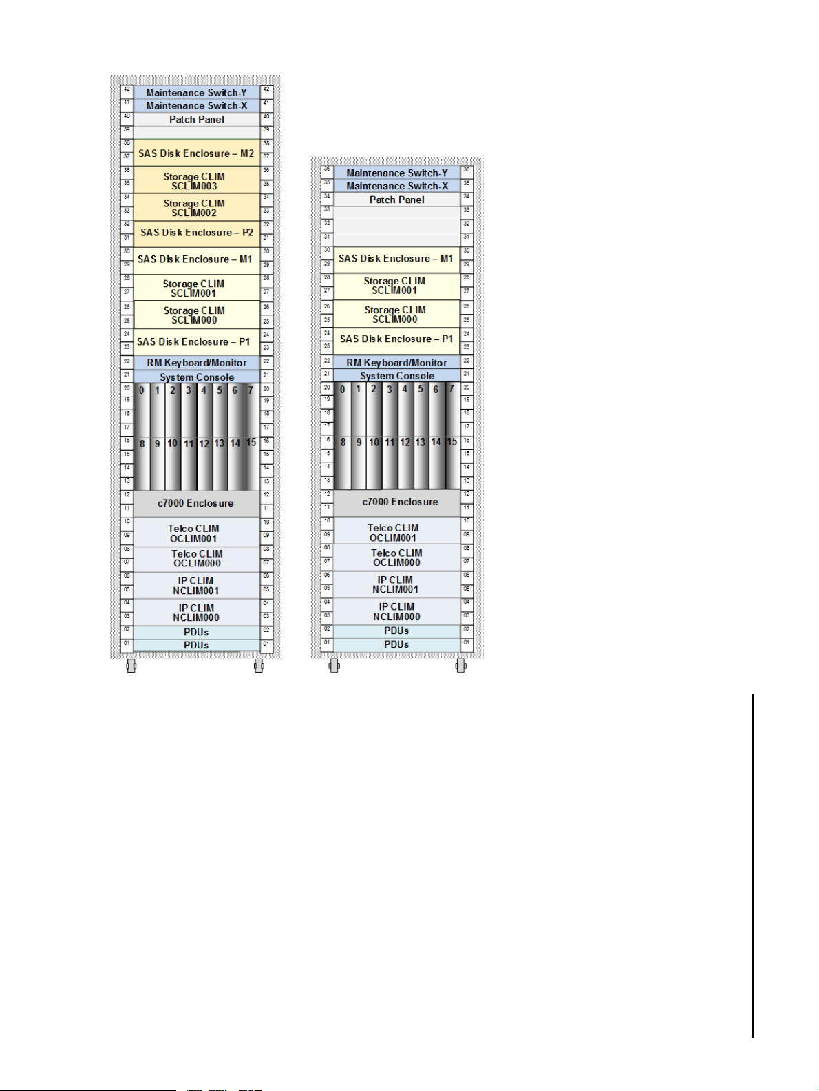
Figure 1 Example NS7 System Configurations (42U and 36U)
8 HPE Integrity NonStop X NS7 Systems
Page 9

Table 2 Characteristics of the NS7 X2
Intel® Xeon® x86 processorsProcessor/Processor model
L16.05 and later RVUsSupported RVU for the system
The core license file is required; see Core Licensing (page 9)2-, 4-, and 6-core software
licensing options
CLIM DVD (Minimum DVD
version required for RVU)
NonStop X system
Minimum CLIMs for
fault-tolerance
Tape support through Storage
CLIMs
Expansion IB Switches
See the CLuster I/O Module (CLIM) Software Compatibility Guide for supported
version
NOTE: This file is preinstalled on new systems
36U or 42URack
2 to 16 processors configured in pairsProcessors
64GB, 128GB, and 192GB memory configurationsMemory
See Planning Kernel Managed Swap (KMS) Space (page 59).Kernel Managed Swap Facility
56 CLuster I/O Modules (CLIMs) — Storage, IP, or TelcoMaximum CLIMs in a 16 CPU
• 2 Storage CLIMs
• 2 Networking CLIMs (IP or Telco)
A Storage CLIM pair supports a maximum of 4 SAS disk enclosuresMaximum SAS disk enclosures
100 per Storage CLIM pairMaximum SAS disk drives
HPE LTO6 Tape Data Cartridge, HPE NonStop BackBox VTC, and HPE NonStop
BackBox VTR
0 to 4 (2 pairs)Minimum/maximum IO
CLIMs
Consoles for fault-tolerance
Interface (NSADI)
Connection to NonStop X
Cluster Solution
Core Licensing
A core license file is required for the system and is automatically included with new NonStop X
systems starting with L15.02 and later. NS7 systems support 2-, 4-, and 6-core license options.
Anytime you upgrade the level of cores, expand your system by adding server blades, or migrate
the system, you must update your license file. Your service provider is responsible for obtaining
and installing this license on your behalf. You will experience a system alarm and dialout if the
license file is missing from your system.
More information
HPE XP 7 Storage Array and HPE XP P9500 Storage ArrayESS support through Storage
This file is required; see Core Licensing (page 9)Core licensing file
Redundant configuration onlyMaintenance LAN
2Minimum NonStop System
Supported with a maximum of 2 NSADI FDR IB switchesNonStop Application Direct
Supported. For more information, see the NonStop X Cluster Solution Manual
NonStop Core Licensing Guide
Migrating NonStop X NS7 Systems
Core Licensing 9
Page 10
NonStop X NS7 Standard and Optional Hardware
• “c7000 Enclosure” (page 10)
• “NonStop X NS7 Server Blades” (page 11)
• “CLuster I/O Modules (CLIMs)” (page 11)
• “SAS Disk Enclosure” (page 13)
• “Maintenance Switch” (page 16)
• “NonStop X FDR IB ADI Switch” (page 16)
• “NonStop IO Expansion IB Switch” (page 16)
• “NonStop System Console” (page 17)
• “UPS and ERM (Optional)” (page 17)
• “Enterprise Storage System (Optional)” (page 18)
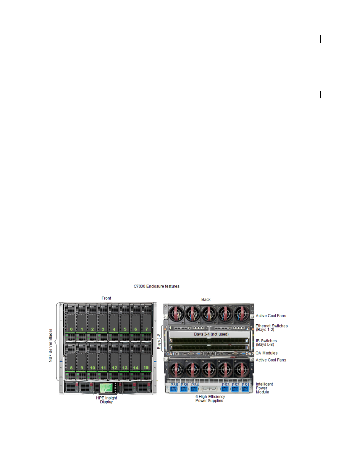
c7000 Enclosure
The c7000 enclosure unifies NonStop X server blades and redundant high-bandwidth InfiniBand
interconnects in a 10U footprint and features:
• Up to 16 half-height NonStop X Server Blades in the c7000 enclosure – configured in pairs.
• Two Interconnect Ethernet switches that provide redundant Maintenance LAN connections
for HSS bootcode download.
• Two Interconnect InfiniBand switches that provide IB connectivity between processors and
I/O infrastructure.
• An Intelligent Infrastructure that supports enhanced midplane signal integrity and compatibility
with HPE Insight Control.
• Two Onboard Administrator (OA) modules manage and monitor the Intelligent Infrastructure
by dynamically allocating power and cooling while also allowing you to monitor and control
resources using the HPE Insight Display as described in the HPE BladeSystem Onboard
Administrator User Guide.
For information about the LEDs associated with the c7000 enclosure components, see the HPE
BladeSystem c7000 Enclosure Setup and Installation Guide.
10 HPE Integrity NonStop X NS7 Systems
Page 11
NonStop X NS7 Server Blades
An NS7 system achieves full software fault tolerance by running the NonStop operating system
on the NonStop X NS7 Server Blades. The NS7 X1 system ships with BL460c Gen8 server
blades and the NS7 X2 ships with BL460c Gen9 server blades.
NOTE: BL460c Gen8 and Gen9 server blades cannot coexist in the same system.
Characteristics in NS7 X1 and NS7 X2 SystemsNS7 Server Blades
• Half-height server blade that features Intel Xeon processors and contains an
• Provides a maximum of 192 GB of memory per server blade
• One HPE 10Gb dual-port FlexibleLOM Ethernet Adapter
• One Infiniband FDR dual-port Host Channel Adapter (HCA)
• Environment Monitoring Services to OA
• Disk bays and Smart Array Controller are not used
More information
Migrating NonStop X NS7 Systems (service providers only)
InfiniBand interface mezzanine card to provide InfiniBand fabric connectivity
CLuster I/O Modules (CLIMs)
NS7 systems support the Storage CLIM, IP CLIM and Telco CLIM which function as I/O or
Ethernet adapters and are managed by the Cluster I/O Protocols (CIP) subsystem.
A CLIM is identified by the number on the rear label; this same number is also listed as the part
number in OSM. Below are sample illustrations of CLIMs.
More information
Cluster I/O Protocols (CIP) Configuration and Management Manual
CLuster I/O Module (CLIM) Software Compatibility Guide
NonStop X NS7 Standard and Optional Hardware 11
Page 12
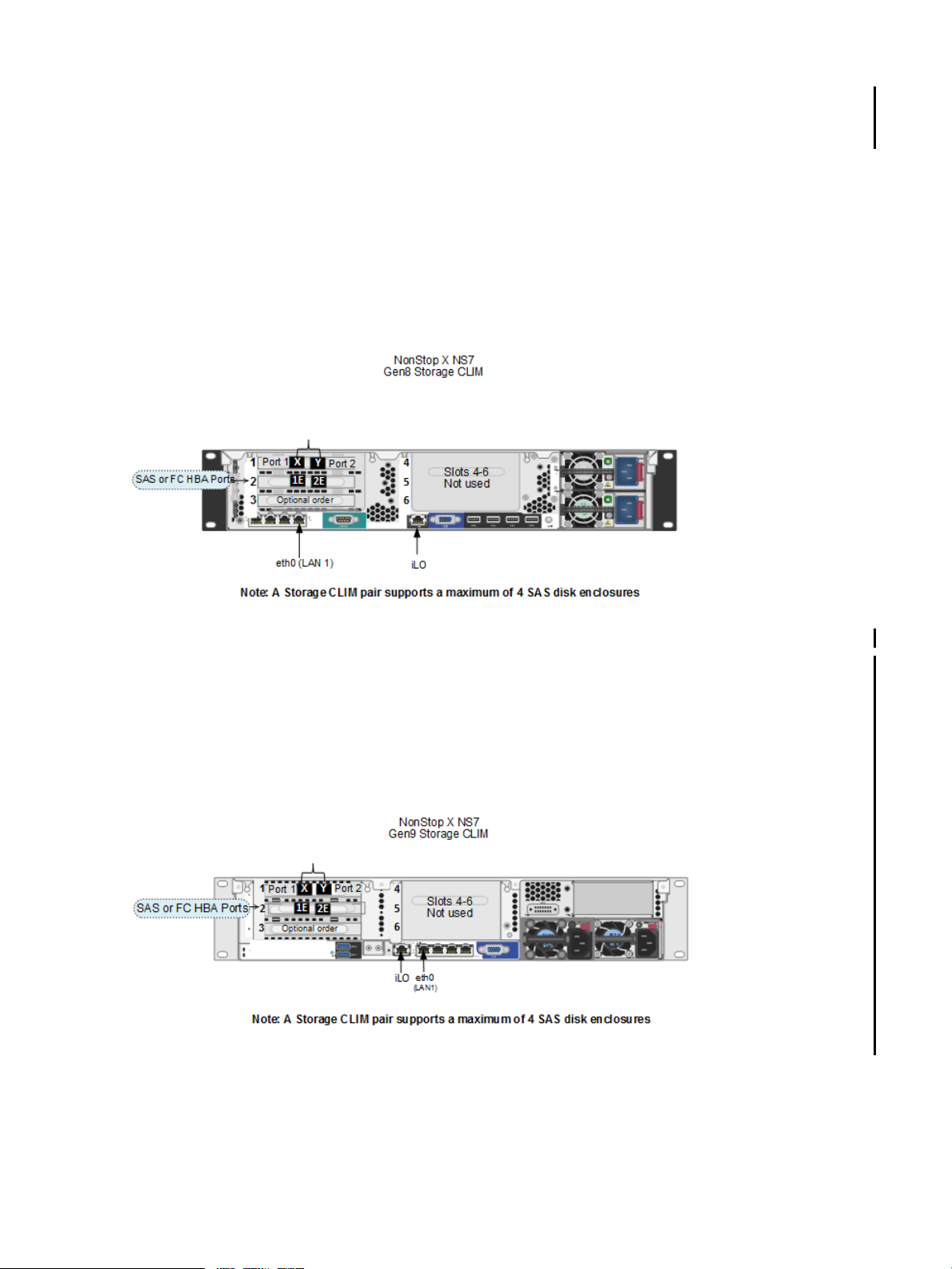
Storage CLIM
The Storage CLIM functions as an I/O adapter supporting SAS disk drives and SAS tapes and
optionally ESS and FC tape devices via 3 PCIe HBA slots. The NS7 X1 ships with Gen8 CLIMs
and the NS7 X2 ships with Gen9 CLIMs.
Gen8 Storage CLIM
Characteristics of Gen8 Storage CLIMHBA in Slot
IB HBA (part of base configuration) provides the InfiniBand fabric connections1
2 SAS HBA with two 6 Gbps SAS ports or
FC HBA with two 8 Gbps FC ports (must be ordered)
Optional order of SAS HBA with two 6 Gbps SAS ports or FC HBA with 8 Gbps FC ports3
Gen9 Storage CLIM
Characteristics of Gen9 Storage CLIMHBA in Slot
IB HBA (part of base configuration) provides the InfiniBand fabric connections1
2 SAS HBA with two 6 Gbps SAS ports or
FC HBA with two 8 Gbps FC ports (must be ordered)
Optional order of SAS HBA with two 6 Gbps SAS ports or FC HBA with 8 Gbps FC ports3
12 HPE Integrity NonStop X NS7 Systems
Page 13
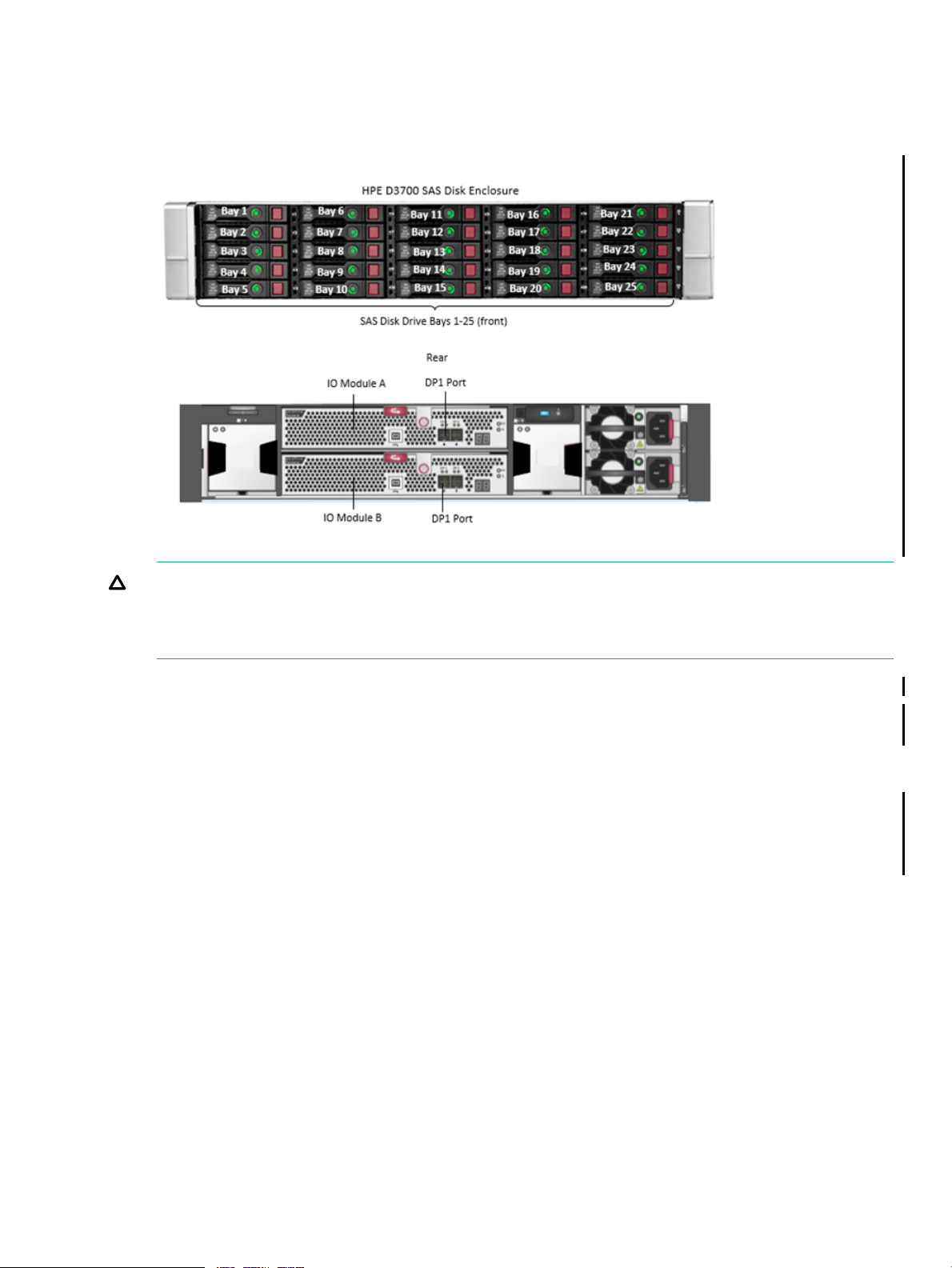
SAS Disk Enclosure
The HPE D3700 SAS disk enclosure provides the storage capacity for the Storage CLIM. This
enclosure holds 25 2.5” SAS Smart Carrier HDDs and SSDs with redundant power and cooling
and is described in the HPE D3600/D3700 Disk Enclosure User Guide.
CAUTION: If the WRITECACHE attribute is enabled on an HDD or SSD disk volume that is
connected to a Storage CLIM, using a rack-mounted UPS to prevent data loss on that volume
is recommended. The WRITECACHE enabled (WCE) option controls whether write caching is
performed for disk writes.
More information
“UPS and Data Center Power Configurations” (page 81)
“Cable Types and Connectors” (page 80)
IP CLIM and Telco CLIM
The IP CLIM and Telco CLIM are sometimes referred to as Networking CLIMs. These CLIMs
function as 10 Gigabit Ethernet (10GbE) adapters and provide five Ethernet ports with configuration
options of all copper or fiber/copper. The NS7 X1 ships with Gen8 CLIMs and the NS7 X2 ships
with Gen9 CLIMs.
NonStop X NS7 Standard and Optional Hardware 13
Page 14
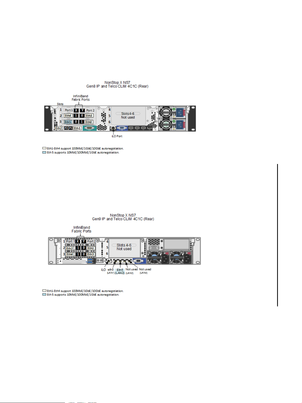
IP or Telco CLIM Option 1 — Four 10GBase-T and One 1GBase-T
Characteristics of Gen8 IP or Telco CLIMInterface
InfiniBand interface card which provides the IB fabric connectionsSlot 1
10GbE 2-port adapter for Eth4 and Eth3 customer portsSlot 2
1GbE 2-port adapter for Eth5 customer port and Eth0 for maintenance support.Slot 3
10GbE 2-port adapter for Eth2 and Eth1 customer portsFlexLOM
Characteristics of Gen9 IP or Telco CLIMInterface
InfiniBand interface card which provides the IB fabric connectionsSlot 1
10GbE 2-port adapter for Eth2 and Eth1 customer portsSlot 2
10GbE 2-port adapter for Eth4 and Eth3 customer ports.Slot 3
1GbE 2-port adapter for Eth5 customer port and Eth0 for maintenance supportFlexLOM
14 HPE Integrity NonStop X NS7 Systems
Page 15
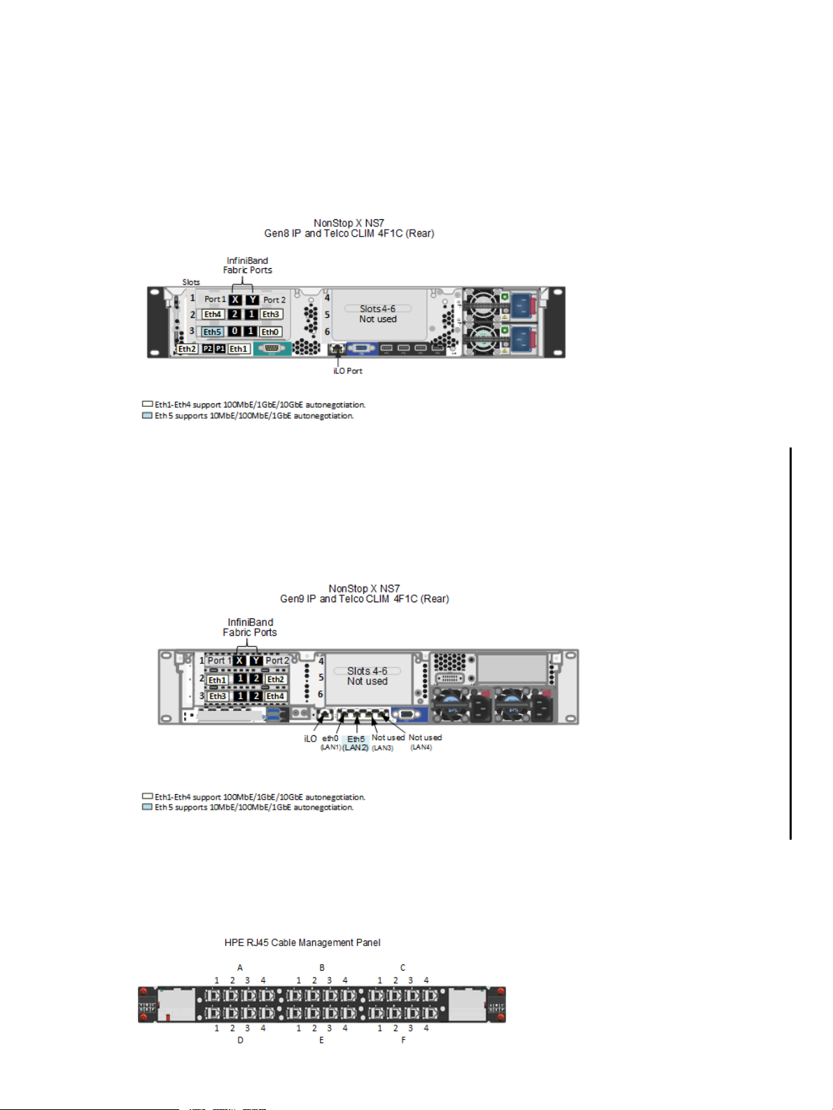
IP or Telco CLIM Option 2 — Four 10GBase-SR and One 1GBase-T
Characteristics of Gen8 IP or Telco CLIMInterface
InfiniBand interface card which provides the IB fabric connectionsSlot 1
10GbE 2-port adapter for Eth4 and Eth3 customer portsSlot 2
1GbE 2-port adapter for Eth5 customer port and Eth0 for maintenance support.Slot 3
10GbE 2-port adapter for Eth2 and Eth1 customer portsFlexLOM
Characteristics of Gen9 IP or Telco CLIMInterface
InfiniBand interface card which provides the IB fabric connectionsSlot 1
10GbE 2-port adapter for Eth1 and Eth2 customer portsSlot 2
10GbE 2-port adapter for Eth3 and Eth4 customer portsSlot 3
1GbE 2-port adapter for Eth5 customer port and Eth0 for maintenance supportFlexLOM
CLIM Cable Management Patch Panels
The HPE CLIM uses two Cable Management patch panels for RJ45 and LC (optical) connections.
The RJ45 patch panel is shown below. Both are preinstalled in new systems. For more information,
refer your service provider to the CLuster I/O (CLIM) Installation and Configuration Guide (15.02+).
NonStop X NS7 Standard and Optional Hardware 15
Page 16
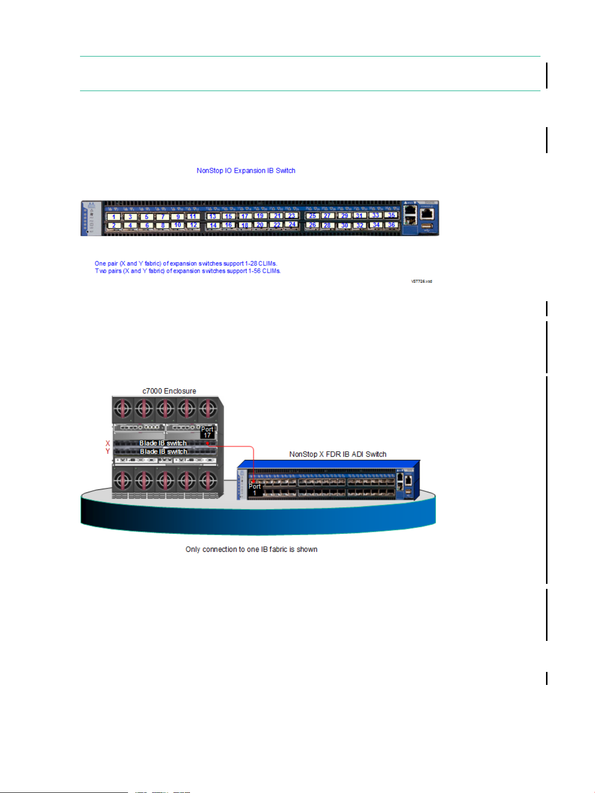
NonStop IO Expansion IB Switch
NOTE: For information about the cluster switch used by the NonStop X Cluster Solution, see
the NonStop X Cluster Solution Manual.
The HPE NonStop IO Expansion 36 port, IB FDR Managed switch provides InfiniBand connectivity
to support CLIM I/O connections.
For information on connecting the switch, refer your service provider to the Technical Document
and the CLuster I/O (CLIM) Installation and Configuration Guide (L15.02+).
NonStop X FDR IB ADI Switch
HPE NonStop X FDR IB ADI switches provide IB fabric connections to support NonStop Application
Direct Interface (NSADI) on NS7 systems running L16.05 and later L-series RVUs. NSADI extends
the existing kernel level IB system interconnect by providing a direct IB interconnect between
NonStop Kernel (NSK) user space and external server-based applications running on Linux.
More information
“NS7 System Installation Specifications” (page 24)
NonStop Application Direct Interface (NSADI) Reference Manual
Replacing a NonStop Blade IB Switch, NonStop IO Expansion IB Switch, or NonStop IB Cluster
Switch in a NonStop X System (service providers only)
Maintenance Switch
The NonStop Maintenance Switch provides the communication network between NS7 system
components. The c7000 enclosure, CLIM, UPS, PDUs, IO Expansion IB Switch, and system
consoles have maintenance interfaces.
A NonStop X system requires multiple connections to the maintenance switch. For more
information, refer your service provider to the Technical Document and the NonStop X System
Hardware Installation Manual.
16 HPE Integrity NonStop X NS7 Systems
Page 17
NonStop System Console
The NonStop system console manages the system and runs maintenance and diagnostic software
in concert with the OSM console tools. An NS7 requires two system consoles running Windows
Server 2012 or Windows Server 2008 to manage the system. New system consoles arrive
preconfigured with all required HPE and third-party console software.
In a future RVU if you need to update your console software, use the HPE NonStop System
Console Installer DVD to install these updates as described in the NonStop System Console
Installer Guide.
NOTE: Procedures related to creating or modifying the dedicated service LAN and the system
console configurations on that LAN, must be performed by an authorized Hewlett Packard
Enterprise service provider as described in the Nonstop Dedicated Service LAN Installation and
Configuration Guide for NonStop X systems.
UPS and ERM (Optional)
A rack-mounted uninterruptible power supply (UPS) is optional but recommended to provide
power during power failures when a site UPS is not available.
NOTE: For information on using OSM to: manage a site UPS, monitor AC power, or for power
fail support, see the OSM Configuration Guide.
Hewlett Packard Enterprise supports these rack-mounted UPS modules. Both support up to two
HPE ERMs per UPS; no mixing of UPS and ERM types.
Single-phase R5000
Three-phase R12000/3
More information
“Power Specifications”
UPS and ERM Checklist
UPS and ERM Checklist
Verify:√
UPS and ERMs are in the lowest portion of the system to avoid tipping and stability issues.
No more than two HPE ERMs are used per UPS; no mixing of UPS or ERM types.
IMPORTANT: The manufacturing default setting ride-through time for the optional Hewlett Packard
Enterprise-supported UPS has been changed by your HPE service provider to an appropriate value for the
system as described in the NonStop X System Hardware Manual (only HPE service providers can refer to this
manual).
UPS ManualsSupported UPS
HPE UPS R5000 User Guide:
HPE UPS Network Module User Guide:
HPE 3 Phase UPS User Guide:
HPE UPS Management Module User Guide:
IMPORTANT: If the optional HPE R5000 UPS has been installed, the UPS output voltage setting must be
manually reset by your HPE service provider as instructed in the NonStop X System Hardware Manual (only
HPE service providers can refer to this manual).
Your UPS configuration is supported. See “UPS and Data Center Power Configurations” (page 81).
NonStop X NS7 Standard and Optional Hardware 17
Page 18
Enterprise Storage System (Optional)
An Enterprise Storage System (ESS) is a collection of magnetic disks, their controllers, and a
disk cache in one or more standalone racks. For more information about these connection types,
see your Hewlett Packard Enterprise service provider.
NOTE: The Fibre Channel Storage Area Network (SAN) switch power cords might not be
compatible with the rack PDU. Contact your Hewlett Packard Enterprise service provider to order
replacement power cords, if needed.
Fibre Channel SwitchesInterfaces, Ports, and Cables<—>Connection
Direct connect
(LC-MMF)
Switched
SAN switch
(LC-MMF)
direct and switched
1
The FC HBA interfaces on the Storage CLIM must be ordered.
For fault tolerance, the primary and backup paths to an ESS logical device (LDEV) must go
through different Fibre Channel switches.
Some Storage Area Network (SAN) procedures, such as reconfiguration, can cause the affected
switches to pause. If the pause is long enough, I/O failure occurs on all paths connected to that
switch. If both the primary and the backup paths are connected to the same switch, the LDEV
goes down. See the documentation that accompanies the ESS.
System Management Tools
OSM Package
1
0Via two Fibre Channel HBA interfaces on Storage CLIM
1 or moreVia four Fibre Channel ports (LC-LC) on a Fibre Channel
1 or moreVia Fibre Channel HBA interfaces on Storage CLIM
1Via two Fibre Channel ports for each direct connectionCombination of
1Via four Fibre Channel ports for each switched connection
The HPE Open System Management (OSM) product is the required system management tool
for NonStop systems. There are several new OSM tools and online help for managing the NS7.
For more information on these changes, see the OSM Configuration Guide or the help within the
OSM tool.
For more information on using OSM tools to manage the HPE Maintenance LAN and system
console configurations, have your service provider refer to the Nonstop Dedicated Service LAN
Installation and Configuration Guide.
Onboard Administrator (OA) and Integrated Lights Out (iLO)
The OA is the enclosure's management, processor, subsystem, and firmware base and supports
the c7000 enclosure and NonStop Server Blades. The OA software is integrated with OSM and
the Integrated Lights Out (iLO) management interface. The iLO enables you to perform activities
on the system from a remote location and provides anytime-access to system management
information such as hardware health, event logs, and configuration to troubleshoot the NonStop X
Server Blades.
The OA can generate a full inventory, status and configuration report of all the components the
OA supports; this is the so called SHOW ALL report. For details on how to generate this report,
see:
http://www.hpe.com/info/OAlog
18 HPE Integrity NonStop X NS7 Systems
Page 19

Management Subsystems for NS7 Systems
The Cluster I/O Protocols (CIP) subsystem provides a configuration and management interface
for I/O on the system. The CIP subsystem has several tools for monitoring and managing the
subsystem. The Subsystem Control Facility (SCF) also provides monitoring and management
of the CIP subsystem. For more information on using these subsystems, see the Cluster I/O
Protocols (CIP) Configuration and Management Manual.
Technical Document for NS7 Systems
Each new NS7 includes a detailed Technical Document that serves as the connection map for
the system and which describes:
• Rack included with the system and each enclosure installed in the rack
• Rack U location at the bottom edge of each enclosure
• Each cable with source, destination, connector type, cable part number, and connection
labels
TIP: It is important to retain all NS7 system records in an Installation Document Packet, including
the Technical Document for your system and any configurations forms. To add CLIM configuration
forms to your Installation Document Packet, have your service provider copy the forms from the
CLuster I/O Module (CLIM) Installation and Configuration Manual (L15.02+)
Component Location and Identification
Each system resource is identified by a unique case sensitive ASCII resource name. A name
can range from one to a maximum of 64 characters. The components in the system ship with
preassigned naming conventions that you can change. For more information, see “Default Naming
Conventions for NS7 Systems” (page 59).
For the IP addresses of system components, refer your service provider to the NonStop X System
Hardware Installation Manual.
Rack and Offset Physical Location
Rack name and rack offset identify the physical location of components in an NS7 system. The
rack name is located on an external label affixed to the rack, which includes the system name
plus a 2-digit rack number.
Rack offset is labeled on the rails in each side of the rack. These rails are measured vertically
in units called U, with one U measuring 1.75 inches (44 millimeters). The rack is 36U with U1
located at the bottom and 36U at the top or 42U with U1 located at the bottom and 42U at the
top. The rack offset is the lowest number on the rack that the component occupies.
Technical Document for NS7 Systems 19
Page 20

2 Site Preparation Guidelines for the NS7 System
This chapter provides guidelines for preparing a site for an NS7 system.
Rack Power and I/O Cable Entry
Depending on how the racks are ordered from Hewlett Packard Enterprise and the routing of the
AC power feeds at the site, AC power cords for the PDUs exit either:
• Top: Power and I/O cables are routed from above the rack.
• Bottom: Power and I/O cables are routed from below the rack.
Emergency Power-Off Switches
Emergency power off (EPO) switches are required by local codes or other applicable regulations
when computer equipment contains batteries capable of supplying more than 750 volt-amperes
(VA) for more than five minutes. Systems that have these batteries also have internal EPO
hardware for connection to a site EPO switch or relay. In an emergency, activating the EPO
switch or relay removes power from all electrical equipment in the computer room (except that
used for lighting and fire-related sensors and alarms).
EPO Requirement for NS7 Systems
NS7 systems without an optional UPS (such as an HPE R12000/3 or HPE R5000 UPS) installed
in the rack do not contain batteries capable of supplying more than 750 volt-amperes (VA) for
more that five minutes, so they do not require connection to a site EPO switch.
EPO Requirement for R5000 UPS
NOTE: Two UPS are required for a single-phase power configuration.
The rack-mounted R5000 UPS is supported for a single-phase power configuration. Each UPS
contains batteries, has an EPO circuit, and can be optionally installed in a rack. For site EPO
switches or relays, consult your Hewlett Packard Enterprise site preparation specialist or electrical
engineer regarding requirements.
If an EPO switch or relay connector is required for your site, contact your Hewlett Packard
Enterprise representative or see the manual for your UPS for connectors and wiring for the UPS.
For information on the R5000 UPS manual, see “UPS and ERM (Optional)” (page 17).
EPO Requirement for R12000/3 UPS
The rack-mounted R12000/3, UPS is supported for a three-phase power configuration. This UPS
contains batteries, has a remote EPO (REPO) port, and can be optionally installed in a rack. For
site EPO switches or relays, consult your Hewlett Packard Enterprise site preparation specialist
or electrical engineer regarding requirements.
If an EPO switch or relay connector is required for your site, contact your Hewlett Packard
Enterprise representative or see the manual for your UPS for connectors and wiring. For
information on the R12000/3 UPS manual, see “UPS and ERM (Optional)” (page 17).
20 Site Preparation Guidelines for the NS7 System
Page 21

Electrical Power and Grounding Quality
Proper design and installation of a power distribution system for a system requires specialized
skills, knowledge, and understanding of appropriate electrical codes and the limitations of the
power systems for computer and data processing equipment. For power and grounding
specifications, see “Enclosure AC Input for NS7 Systems” (page 47).
Power Quality
This equipment is designed to operate reliably over a wide range of voltages and frequencies,
described in “Enclosure AC Input for NS7 Systems” (page 47). However, damage can occur if
these ranges are exceeded. Severe electrical disturbances can exceed the design specifications
of the equipment. Common sources of such disturbances are:
• Fluctuations occurring within the facility’s distribution system
• Utility service low-voltage conditions (such as sags or brownouts)
• Wide and rapid variations in input voltage levels or input power frequency
• Electrical storms or large inductive sources (such as motors and welders)
• Faults in the distribution system wiring (such as loose connections)
To protect the system from electrical disturbances, use a dedicated power distribution system,
power conditioning equipment, and lightning arresters on power cables. For assistance, consult
with your Hewlett Packard Enterprise site preparation specialist or power engineer.
Grounding Systems
The site building must provide a power distribution safety ground/protective earth for each AC
service entrance to all system equipment. This safety grounding system must comply with local
codes and any other applicable regulations for the installation locale.
For proper grounding/protective earth connection, consult with your Hewlett Packard Enterprise
site preparation specialist or power engineer.
Power Consumption
The power consumption and inrush currents per connection can vary because of the unique
combination of enclosures housed in the rack. Calculate the total power consumption for the
hardware installed in the rack as described in “NS7 Enclosure Power Loads” (page 48).
Cooling and Humidity Control
Cooling airflow through each enclosure in the system is front-to-back. Because of high heat
densities and hot spots, an accurate assessment of air flow around and through the system
equipment and specialized cooling design is essential for reliable system operation. For an airflow
assessment, consult with your Hewlett Packard Enterprise cooling consultant or your heating,
ventilation, and air conditioning (HVAC) engineer.
NOTE: Failure of site cooling with the system continuing to run can cause rapid heat buildup
and excessive temperatures within the hardware. Excessive internal temperatures can result in
full or partial system shutdown. Ensure that the site’s cooling system remains fully operational
when the system is running.
Use the “NS7 Heat Dissipation Specifications and Worksheet ” (page 55) to calculate the total
heat dissipation for the hardware installed in each rack. For air temperature levels at the site,
see “Operating Temperature, Humidity, and Altitude Specifications for NS7 Systems” (page 56).
Electrical Power and Grounding Quality 21
Page 22
Weight
Total weight must be calculated based on what is in the specific rack, as described in “NS7 Rack
and Enclosure Weights With Worksheet” (page 52).
Flooring
NonStop NS7 systems can be installed either on the site’s floor with the cables entering from
above the equipment or on raised flooring with power and I/O cables entering from underneath.
Because cooling airflow through each enclosure in the racks is front-to-back, raised flooring is
not required for system cooling.
The site floor structure and any raised flooring (if used) must be able to support the weight of the
installed system, individual racks, and enclosures as they are moved into position. To determine
the total weight of the installation, see “NS7 Rack and Enclosure Weights With Worksheet”
(page 52).
For your site’s floor system, consult with your Hewlett Packard Enterprise site preparation specialist
or an appropriate floor system engineer. If raised flooring is to be used, the rack is optimized for
placement on 24-inch floor panels.
Dust and Pollution Control
NS7 systems do not have air filters. Any computer equipment can be adversely affected by dust
and microscopic particles in the site environment. Airborne dust can blanket electronic components
on printed circuit boards, inhibiting cooling airflow and causing premature failure from excess
heat, humidity, or both. Metallically conductive particles can short circuit electronic components.
Tape drives and some other mechanical devices can experience failures resulting from airborne
abrasive particles.
For recommendations to keep the site as free of dust and pollution as possible, consult with your
heating, ventilation, and air conditioning (HVAC) engineer or your Hewlett Packard Enterprise
site preparation specialist.
Zinc Particulates
Over time, fine whiskers of pure metal can form on electroplated zinc, cadmium, or tin surfaces
such as aged raised flooring panels and supports. If these whiskers are disturbed, they can break
off and become airborne, possibly causing computer failures or operational interruptions. This
metallic particulate contamination is a relatively rare but possible threat. Kits are available to test
for metallic particulate contamination, or you can request that your site preparation specialist or
HVAC engineer test the site for contamination before installing any electronic equipment.
Space for Receiving and Unpacking the System
WARNING! A fully populated rack is unstable when moving down the unloading ramp from its
shipping pallet. A falling rack can cause serious or fatal personal injury.
Verify√
There is adequate space to receive and unpack the system from shipping cartons and pallets and to remove
equipment using supplied ramps. For physical dimensions of the system equipment, see “Dimensions and
Weights for NS7 AC Systems” (page 50).
Enough personnel are present to remove and transport each rack to the installation site.
Tiled or carpeted pathways have temporary hard floor covering to facilitate moving the racks which have small
casters.
Door and hallway width and height, the floor and elevator loading, accommodate the system equipment,
personnel, and lifting or moving devices. If necessary, enlarge or remove any obstructing doorway or wall.
22 Site Preparation Guidelines for the NS7 System
Page 23

Operational Space for an NS7 System
Verify√
NS7 system site layout, uses the equipment dimensions, door swing, and service clearances listed in
“Dimensions and Weights for NS7 AC Systems” (page 50) and takes advantage of existing lighting and electrical
outlets.
Airflow direction and current or future air conditioning ducts are not obstructed. Eliminate any obstructions to
equipment intake or exhaust air flow. See“Cooling and Humidity Control” (page 21).
Adequate space planning to allow for future equipment.
Site layout plan includes provisions for things such as channels or fixtures used for cable routing, cables, patch
panels, and storage areas.
Operational Space for an NS7 System 23
Page 24

3 NS7 System Installation Specifications
This chapter provides specifications necessary for system installation planning. All specifications
in this chapter assume that each enclosure in the rack is fully populated. The maximum current
for each AC service depends on the number and type of enclosures installed in the rack. Power,
weight, and heat loads are less when enclosures are not fully populated; for example, a SAS
disk enclosure with fewer disks.
Racks
The rack is an EIA standard 19-inch , 36U or 42U rack. The rack comes equipped with front and
rear doors and includes a rear extension that makes it deeper than some industry-standard racks.
The PDUs described in “Power Distribution Unit (PDU) Types for a Rack ” (page 24) are mounted
along the rear extension without occupying any U-space in the rack and are oriented inward,
facing the components within the rack.
NOTE: For instructions on grounding the Enterprise series rack (formerly known as the Intelligent
rack) using the HPE Rack Ground Bonding Kit (BW891A), ask your service provider to see the
instructions in the:
• HP Rack Options Installation Guide
• http://www.hpe.com/support/Intelligent_Series_Rack_Manuals.
Power Distribution Unit (PDU) Types for a Rack
The Enterprise series rack (formerly known as the Intelligent rack) supports Intelligent PDUs
(iPDUs) and Modular PDUs. Both PDU types use a core and extension bar design with these
characteristics:
• PDU cores power the extension bars and c7000 enclosure.
• PDU cores are mounted at the lowest possible U location in the rack. Two PDUs are mounted
in the same U location (rear and front).
• Extension bars are mounted on the rear vertical rails of the rack.
• Rear-mounted PDU cores connect to the extension bars on the right side of the rack.
• Front-mounted PDU cores connect to the extension bars on the left side of the rack.
• If the rack is equipped with a UPS, the UPS outputs connect to the front-mounted PDU
cores.
NOTE: A rack with a c7000 enclosure requires a four PDU core configuration. Racks without
a c7000 enclosure use a two PDU core configuration.
24 NS7 System Installation Specifications
Page 25
This table lists the PDUs, supported configurations, and links to examples that use a 42U rack.
Examples of ConfigurationsSupported PDU ConfigurationsPDU Types
Four PDU cores without UPSiPDU
Four PDU cores with UPS
Two PDU cores without UPS
Two PDU cores with UPS
Four PDU cores without UPSModular
Four PDU cores with UPS
Two PDU cores without UPS
Two PDU cores with UPS
• 4 single-phase iPDUs without UPS (page 26)
• 4 iPDUs with single-phase UPS (page 27)
• 4 iPDUs with three-phase UPS (page 28)
• 2 iPDUs without UPS (page 29)
• 2 iPDUs with single-phase UPS (page 30)
• 2 iPDUs with three-phase UPS (page 31)
• 4 mPDUs without UPS (page 32)
• 4 mPDUs with single-phase UPS (page 33)
• 4 mPDUs with three-phase UPS (page 34)
• 2 mPDUs without UPS (page 35)
• 2 mPDUs with single-phase UPS (page 36)
• 2 mPDUs with three-phase UPS (page 37)
Power Distribution Unit (PDU) Types for a Rack 25
Page 26
Four Intelligent PDUs Without UPS – (NA/JPN and INTL, Single-Phase and Three-Phase)
This illustration shows the power configuration for four iPDUs (without UPS) in a rack. For detailed
power specifications and connector types, see “Power Specifications” (page 45).
Figure 2 Four iPDUs Without UPS — (NA/JPN and INTL, Single-Phase and Three-Phase)
26 NS7 System Installation Specifications
Page 27
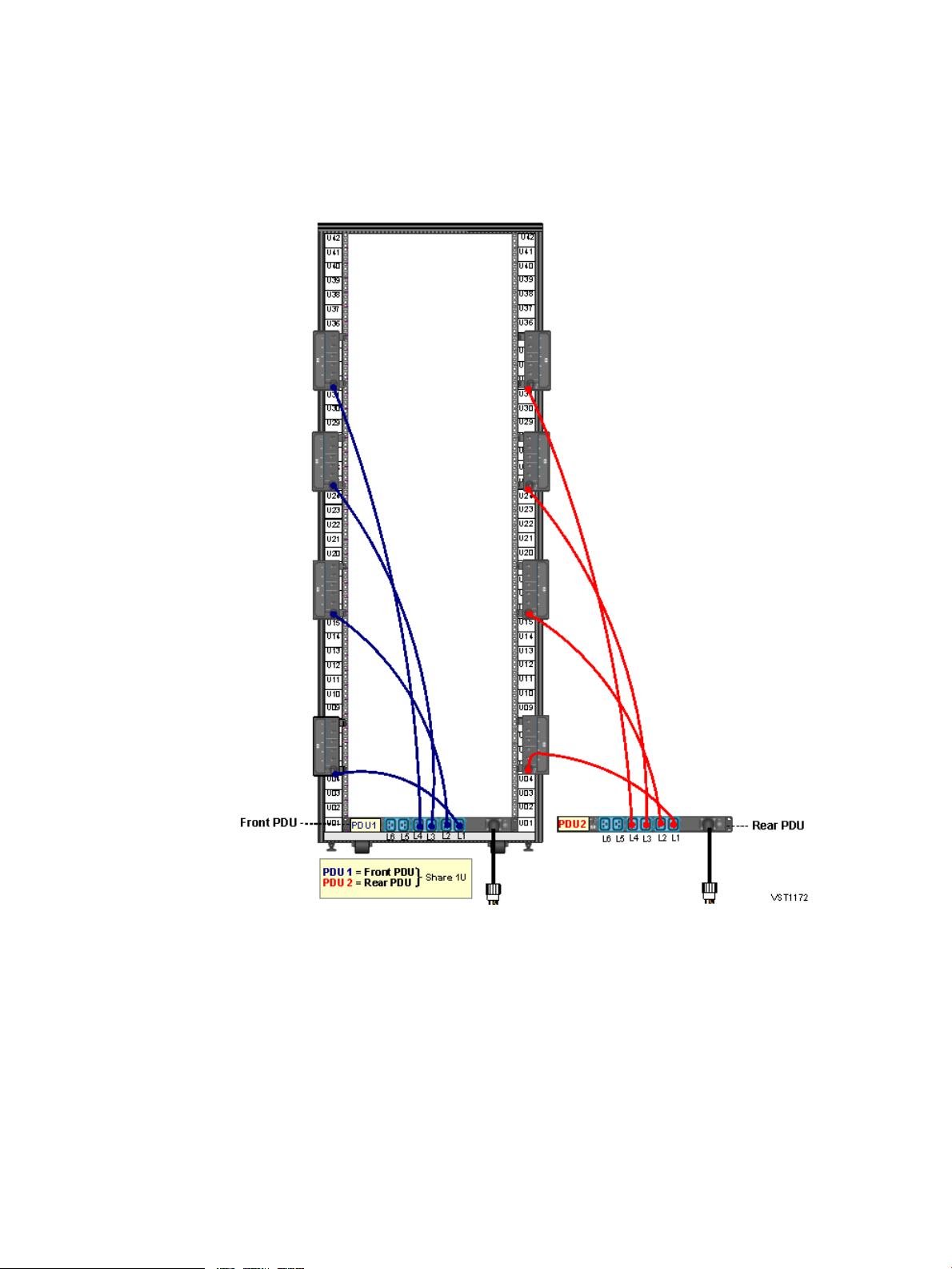
Four Intelligent PDUs With Single-Phase UPS – (NA/JPN and INTL)
This illustration shows the power configuration for four iPDUs and two single-phase UPS's in a
rack. For detailed power specifications and connector types, see “Power Specifications” (page 45).
Figure 3 Four iPDUs With Single-Phase UPS — (NA/JPN and INTL)
Power Distribution Unit (PDU) Types for a Rack 27
Page 28
Four Intelligent PDUs With Three-Phase UPS (NA/JPN and INTL)
This illustration shows the power configuration for four iPDUs and a three-phase UPS in a rack.
For detailed power specifications and connector types, see “Power Specifications” (page 45).
Figure 4 Four iPDUs With Three-Phase UPS — (NA/JPN and INTL)
28 NS7 System Installation Specifications
Page 29
Two Intelligent PDUs Without UPS — (NA/JPN and INTL, Single-Phase and Three-Phase)
This illustration shows the connections for two iPDUs in a rack without a UPS. For detailed power
specifications and connector types, see “Power Specifications” (page 45).
Figure 5 Two Intelligent PDUs Without UPS— (NA/JPN and INTL, Single-Phase and
Three-Phase)
Power Distribution Unit (PDU) Types for a Rack 29
Page 30

Two Intelligent PDUs With Single-Phase UPS — (NA/JPN and INTL)
This illustration shows the power configuration for two iPDUs and a single-phase UPS in a rack.
For detailed power specifications and connector types, see “Power Specifications” (page 45).
Figure 6 Two Intelligent PDUs With Single-Phase — (NA/JPN and INTL)
30 NS7 System Installation Specifications
Page 31

Two Intelligent PDUs With Three-Phase UPS — (NA/JPN and INTL)
This illustration shows the power configuration for two iPDUs and a three-phase UPS in a rack.
For detailed power specifications and connector types, see “Power Specifications” (page 45).
Figure 7 Two Intelligent PDUs With Three-Phase UPS — (NA/JPN and INTL)
Power Distribution Unit (PDU) Types for a Rack 31
Page 32

Four Modular PDUs Without UPS — (NA and JPN, Single-Phase and Three-Phase)
This illustration shows the power configuration for four modular PDUs in a rack without a UPS.
For detailed power specifications and connector types, see “Power Specifications” (page 45).
Figure 8 Four Modular PDUs Without UPS — (NA/JPN and INTL, Single-Phase and
Three-Phase)
32 NS7 System Installation Specifications
Page 33

Four Modular PDUs With Single-Phase UPS (NA/JPN and INTL)
This illustration shows the power configuration for four modular PDUs and two single-phase
UPS's in a rack. For detailed power specifications and connector types, see “Power Specifications”
(page 45).
Figure 9 Four Modular PDUs With Single-Phase UPS — (NA/JPN and INTL)
Power Distribution Unit (PDU) Types for a Rack 33
Page 34

Four Modular PDUs With Three-Phase UPS (NA/JPN and INTL)
This illustration shows the power configuration for four modular PDUs and a three-phase UPS
in a rack. For detailed power specifications and connector types, see “Power Specifications”
(page 45).
Figure 10 Four Modular PDUs With Three-Phase UPS — (NA/JPN and INTL)
34 NS7 System Installation Specifications
Page 35

Two Modular PDUs Without UPS — (NA/JPN and INTL, Single-Phase and Three-Phase)
This illustration shows the power configuration for two modular PDUs without a UPS in a rack.
For detailed power specifications and connector types, see “Power Specifications” (page 45).
Figure 11 Two Modular PDUs Without UPS — (NA/JPN and INTL, Single-Phase and
Three-Phase)
Power Distribution Unit (PDU) Types for a Rack 35
Page 36

Two Modular PDU Connections With Single-Phase UPS — (NA/JPN and INTL)
This illustration shows the connections for two modular PDUs with a single-phase UPS in a rack.
For detailed power specifications and connector types, see “Power Specifications” (page 45).
Figure 12 Two Modular PDUs With a Single-Phase UPS — (NA/JPN and INTL)
36 NS7 System Installation Specifications
Page 37

Two Modular PDU Connections With Three-Phase UPS — (NA/JPN and INTL)
This illustration shows the connections for two modular PDUs with a three-phase UPS in a rack.
For detailed power specifications and connector types, see “Power Specifications” (page 45).
Figure 13 Two Modular PDUs With a Three-Phase UPS — (NA/JPN and INTL)
Power Distribution Unit (PDU) Types for a Rack 37
Page 38

AC Power Feeds in the Rack
Systems can be ordered with the AC power cords for the PDU installed either:
• Top: Power and I/O cables are routed from above the rack.
• Bottom: Power and I/O cables are routed from below the rack.
ExamplesAC Power Feeds...
Without UPS
With Single-Phase UPS
With Three-Phase UPS
• Example AC feed at bottom of rack without
UPS (page 39)
• Example AC feed at top of rack without UPS (page 40)
• Example AC feed at top of rack with single-phase
UPS (page 41)
• Example AC feed at the bottom of rack with
single-phase UPS (page 42)
• Example AC feed at top of rack with three-phase
UPS (page 43)
• Example AC feed at the bottom of rack with
three-phase UPS (page 44)
NOTE: The example power feed illustrations on the following pages show the connections to
two PDUs and one UPS. If you have a power configuration with four PDUs and two UPS's, you
will need to make additional connections.
38 NS7 System Installation Specifications
Page 39

Figure 14 Example of Bottom AC Power Feed in a Rack (Without UPS)
AC Power Feeds in the Rack 39
Page 40

Figure 15 Example of Top AC Power Feed in a Rack (Without UPS)
40 NS7 System Installation Specifications
Page 41

Figure 16 Example of Top AC Power Feed in a Rack (With Single-Phase UPS)
AC Power Feeds in the Rack 41
Page 42

Figure 17 Example of Bottom AC Power Feed in a Rack (With Single-Phase UPS)
42 NS7 System Installation Specifications
Page 43

Figure 18 Example of Top AC Power Feed in a Rack (With Three-Phase UPS)
AC Power Feeds in the Rack 43
Page 44

Figure 19 Example of Bottom AC Power Feed in a Rack (With Three-Phase UPS)
Each PDU is wired to distribute the load segments to its receptacles.
44 NS7 System Installation Specifications
Page 45

AC Input Power for NS7 Racks
This topic provides power specifications for AC input power in NS7 system racks.
Power Specifications
CAUTION: Be sure the hardware configuration and resultant power loads of each rack within
the system do not exceed the capacity of the branch circuit according to applicable electrical
codes and regulations.
Select circuit breaker ratings according to local codes and any applicable regulations for the
circuit capacity. Note that circuit breaker ratings vary if your system includes an optional
rack-mounted UPS.
Table 3 North America/Japan Single-Phase Power Specifications
See...PhaseRegion
Table 3 (page 45)Single-PhaseNorth America/Japan
Table 4 (page 46)Three-Phase
Table 5 (page 46)Single-PhaseInternational
Table 6 (page 47)Three-Phase
4 x C13
UPS outputs are connected to the compatible PDU inputs.Notes
Modular PDU 1-phaseiPDU 1-phaseR5000 1-phase UPSNorth America/Japan
24 A24 A4500 WOutput Load
200 – 240 V200 – 208 V200 – 208 VInput Voltage
NEMA L6-30PNEMA L6-30PNEMA L6-30PInput Connector
N/AN/A200 – 208 VOutput Voltage
4 x C196 x C191 x L6-30ROutput Connectors
(28 x C13)(20 x C13)4 x C19
AC Input Power for NS7 Racks 45
Page 46

Table 4 North America/Japan Three-Phase Power Specifications
UPS outputs are connected to the compatible PDU inputs.Notes
Modular PDU 3-phaseiPDU 3-phaseR12000 3-phase UPSNorth America/Japan
24 A24 A12 kWOutput Load
208V 3P Delta208V 3P Delta208V 3P WyeInput Voltage
NEMA L15-30PNEMA L15-30PIEC309 560P9Input Connector
N/AN/A208V 3P DeltaOutput Voltage
6 x C196 x C192 x NEMA L15-30ROutput Connectors
(42 x C13)(20 x C13)
Table 5 International Single-Phase Power Specifications
4 x C13
UPS outputs are connected to the compatible PDU inputs.Notes
Modular PDU 1-phaseiPDU 1-phaseR5000 1-phase UPSInternational
32 A32 A4500 WOutput Load
200 – 240 V200 – 240 V220 – 240 VInput Voltage
IEC309 332P6IEC309 332P6IEC309 332P6Input Connector
N/AN/A220 – 240 VOutput Voltage
4x C196 x C191 x IEC309 332R6Output Connectors
(28 x C13)(20 x C13)4 x C19
46 NS7 System Installation Specifications
Page 47

Table 6 International Three-Phase Power Specifications
UPS outputs are connected to the compatible PDU inputs.Notes
Enclosure AC Input for NS7 Systems
Modular PDU 3-phaseiPDU 3-phaseR12000 3-phase UPSInternational
16 A/phase16 A/phase12 kWOutput Load
380-415V 3P Wye380-415V 3P Wye380-415V 3P WyeInput Voltage
IEC309 516P6IEC309 516P6IEC309 532P6Input Connector
N/AN/A400V 3P WyeOutput Voltage
6 x C19 (20 A)6 x C192 x IEC309 309 516C6Output Connectors
(42 x C13)(20 x C13)
Enclosures (IP CLIM, SAS disk enclosure, and so forth) require:
ValueSpecification
200/208/220/230/240 V AC RMSNominal input voltage
180-264 V ACVoltage range
50 or 60 HzNominal line frequency
47-53 Hz or 57-63 HzFrequency ranges
1Number of phases
Single-phase c7000 enclosures require:
ValueSpecification
200-240 VACVoltage range
50 or 60 HzNominal line frequency
47-53 Hz or 57-63 HzFrequency ranges
1Number of phases
AC Input Power for NS7 Racks 47
Page 48

NS7 Enclosure Power Loads
The total power and current load for a rack depends on the number and type of enclosures
installed in it. Therefore, the total load is the sum of the loads for all installed enclosures.
In normal operation, the AC power is split equally between the power feeds on the two sides (left
and right) of the rack. However, if AC power fails on one side of the rack, the power feed(s) on
the remaining side must carry the power for all enclosures in that rack.
NOTE: For NS7 CG X2 system specifications, see “System Installation Specifications for NS7
CG Systems” (page 70).
Power and current specifications for each type of enclosure are:
Enclosure Type
Products used by NS7 X1
AC systems
BL460c Gen8 CPU
(64 GB RAM)
BL460c Gen8 CPU
(128 GB RAM)
BL460c Gen8 CPU
(192 GB RAM)
Products used by NS7 X2
AC systems
BL460c Gen9 CPU
(64 GB RAM)
BL460c Gen9 CPU
(128 GB RAM)
BL460c Gen9 CPU
(192 GB RAM)
AC Power Lines per
Enclosure
-
-
-
Typical Power
Consumption (VA)
Maximum Power
1
Consumption (VA)
230230-
260260-
290290-
300300
315315
330330
2
Common products used by
NS7 X1 and NS7 X2 AC
systems:
FDR IB ADI switch (for
NSADI)
FDR IB cluster switch (for
NonStop X Cluster Solution)
Gen8 Networking CLIM,
4C/1C (IP or Telco)
Gen8 Networking CLIM,
3C/2F (IP or Telco)
48 NS7 System Installation Specifications
12508106c7000 enclosure
2342072
2342072FDR IB switches expansion
2342072
1601302Gen8 Storage CLIM
1561262
1581282
1901402Gen9 Storage CLIM
Page 49

Enclosure Type
Gen9 Networking CLIM,
4C/1C (IP or Telco)
Gen9 Networking CLIM,
3C/2F (IP or Telco)
D3700 SAS disk enclosure,
empty
SC
SAS, SFF, SC
monitor
AC Power Lines per
Enclosure
Typical Power
Consumption (VA)
Maximum Power
1
Consumption (VA)
1851352
1851352
7732GB Memory kit
125752
66-400GB SSD, 12G SAS, SFF,
74-300GB, 15k rpm HDD, 12G
1591Maintenance switch (Ethernet)
1291291Rack-mount system console
36361Console keyboard and
1451351Deskside system console
2
monitor
1
Typical = measured at 22C ambient temp
2
Maximum = measured at 35C ambient temp
26231Deskside system Console
NS7 Enclosure Power Loads 49
Page 50

Dimensions and Weights for NS7 AC Systems
This subsection provides the dimensions and weights for racks and enclosures.
Plan View of the Racks
Service Clearances for NS7 Racks
Aisles: 6 feet (182.9 centimeters)
Front: 3 feet (91.4 centimeters)
Rear: 3 feet (91.4 centimeters)
Unit Sizes for NS7 Systems
Height (U)Enclosure Type
42 or 36Rack
10c7000 enclosure
2CLIMs
2SAS disk enclosures
1CLIM patch panel (RJ45 and Fiber)
1FDR IB ADI switch
1FDR IB managed switch, expansion
1IB FDR managed switch, IB cluster
1Maintenance switch (Ethernet)
50 NS7 System Installation Specifications
3R5000 UPS (single-phase power)
3ERM for single-phase UPS
6R12000/3 UPS (three-phase power)
3ERM for three-phase UPS
Page 51

Height (U)Enclosure Type
1Rack-mount system console
1Keyboard and monitor for system console
42U Rack Physical Specifications for NS7 Systems
WeightDepthWidthHeightItem
cmin.cmin.cmin.
(palletized)
36U Rack Specifications for NS7 Systems
(palletized)
12147.659.023.3199.978.7Rack
14757.89035.421885.8Shipping
cmin.cmin.cmin.
12147.659.0623.3173.168.2Rack
14757.89035.421885.8Shipping
Depends on
the
enclosures
installed. See
“NS7 Rack
and
Enclosure
Weights With
Worksheet”
(page 52).
WeightDepthWidthHeightItem
Depends on
the
enclosures
installed. See
“NS7 Rack
and
Enclosure
Weights With
Worksheet”
(page 52).
NS7 Enclosure Dimensions
Type
enclosure
(1-phase)
models)
disk enclosure
panels
switch
(Ethernet)
DepthWidthHeightEnclosure
cmincmincmin
81.23244.417.544.117.4c7000
662644.517.58.63.4CLIMs (all
54.321.444.717.68.63.4D3700 SAS
71.928.347.818.84.31.7CLIM patch
20.38.044.217.44.61.8Maintenance
Dimensions and Weights for NS7 AC Systems 51
Page 52

Type
system
console
display
PDU
switches
IB expansion
switch
IB cluster
switch
IB ADI switch
(single-phase
power)
DepthWidthHeightEnclosure
cmincmincmin
60.915.0742.717.114.31.7Rack-mount
42.316.6643.116.974.31.7Keyboard and
14.25.644.517.54.11.6Modular PDU
19.17.544.517.54.11.6Intelligent
62.724.742.716.84.31.7FDR IB
74.429.343.717.212.75.0R5000 UPS
single-phase
power with
R5000 UPS
UPS
(three-phase
power)
three-phase
power
NS7 Rack and Enclosure Weights With Worksheet
The total weight of each rack is the sum the weights of the rack plus each enclosure installed in
it. Use this worksheet to determine the total weight:
Enclosure Type
Enclosures
14431836U rack
Maximum
payload weight
for the 36U rack:
3000 lbs (1360
kg).
71.928.343.817.212.75.0ERM for
36.514.4662626.110.3R12000/3
662643.817.213.15.1ERM for
TotalWeightNumber of
kglbskglbs
Maximum
payload weight
for the 42U rack:
3000 lbs (1360
kg).
52 NS7 System Installation Specifications
15133342U rack
Page 53

Enclosure Type
NonStop X NS7
Server Blade:
(64GB RAM)
(128GB RAM)
(192GB RAM)
(64GB RAM)
(128GB RAM)
(192GB RAM)
Storage/Networking:
TotalWeightNumber of
Enclosures
kglbskglbs
122270c7000 enclosure
1125BL460c Gen8
1227BL460c Gen8
1329BL460c Gen8
512BL460c Gen9
512BL460c Gen9
512BL460c Gen9
enclosure, empty
12G SAS, SFF,
2.5in SC
HDD, 12G SAS,
SFF, 2.5 in SC
panels
switch (Ethernet)
IB FDR
managed switch,
expansion
IB cluster switch
IB ADI switch
2455Gen8 CLIM
2045Gen9 CLIM
1738SAS disk
.451400GB SSD,
.15.34300GB, 15k rpm
.04.1Disk blank
25CLIM patch
36Maintenance
921IB switches
Manageability:
system console
display for
console
818Rack-mounted
510Keyboard and
Dimensions and Weights for NS7 AC Systems 53
Page 54

Enclosure Type
Power
Distribution:
TotalWeightNumber of
Enclosures
kglbskglbs
Modular PDU
core (in a rack)
(for Modular
PDU in a rack)
Intelligent PDU
core (in a rack)
517
NOTE: One
modular PDU core
weighs 17
pounds. A 4
modular PDU core
configuration in a
rack would weigh
76 lbs (68 lbs for
the PDU cores +
8 lbs for extension
bars).
.451Extension bar
1227
NOTE: One
iPDU core weights
27 lbs. A 4 iPDU
core configuration
would weigh 172
lbs (108 lbs for
iPDU cores + 64
lbs for extension
bars).
(for Intelligent
PDU in a rack)
(single-phase
power)
single-phase
power
R12000/3 UPS
(three-phase
power)
runtime module
(ERM) for
three-phase
power
307 (with
batteries)
135 (without
batteries)
18Extension bar
57126R5000 UPS
63139ERM
139 (with
batteries)
60 (without
batteries)
77170Extended
----Total
54 NS7 System Installation Specifications
Page 55

Rack Stability for NS7 Systems
Rack stabilizers are required when you have less than four racks bayed together.
NOTE: Rack stability is of special concern when equipment is routinely installed, removed, or
accessed within the rack. Stability is addressed through the use of leveling feet, baying kits, fixed
stabilizers, and/or ballast. Use baying kits to bay racks to racks of the same height. In all cases,
a rack cannot be bayed with another rack of a different height.
NOTE: For instructions on best practices for the Enterprise series rack (formerly known as the
Intelligent rack) or for using the HPE Rack Ground Bonding Kit (BW891A), ask your service
provider to see the instructions in the:
• HP Rack Options Installation Guide
• http://www.hpe.com/support/Intelligent_Series_Rack_Manuals.
Environmental Specifications for NS7 AC Systems
NS7 Heat Dissipation Specifications and Worksheet
(single-phase)
blade, 64GB
blade, 64GB
blade, 128GB
blade, 192GB
Switch
(NonStop X Cluster
Solution)
Number InstalledEnclosure Type
Unit Heat
(BTU/hour, Typical
Heat Dissipation)
Maximum Heat
Dissipation)
38562764c7000 enclosure
785785BL460c Gen8 server
10241024BL460c Gen9 server
10751075BL460c Gen9 server
11261126BL460c Gen9 server
798706IB FDR ADI Switch
798706IB FDR I/O Expansion
798706IB FDR cluster switch
546444Gen8 Storage CLIM
Total (BTU/hour)Unit Heat (BTU/hour,
Networking CLIM
4C/1C
Networking CLIM
4F/1C
Networking CLIM
4C/1C
529427Gen8 10GbE
511409Gen8 10GbE
10241024Gen9 Storage CLIM
631461Gen9 10GbE
Rack Stability for NS7 Systems 55
Page 56

Networking CLIM
4F/1C
empty
15k rpm
15k rpm
Number InstalledEnclosure Type
Unit Heat
(BTU/hour, Typical
Heat Dissipation)
Maximum Heat
Dissipation)
Total (BTU/hour)Unit Heat (BTU/hour,
631461Gen9 10GbE
614426SAS disk enclosure,
2313SAS HDD, 2.5 inches,
2414SAS, SSD, 2.5in, SC,
5131Maintenance switch
(Ethernet)
1
569569Rack-mounted
system console
129129Console keyboard
and display
1
Maintenance switch has only one plug.
Operating Temperature, Humidity, and Altitude Specifications for NS7 Systems
Specification
Operating Range
1
Recommended Range
41° to 95° F (5° to 35° C)Temperature (rack-mounted
system console, and
maintenance switch)
-50° to 95° F (10° to 35° C)Temperature (c7000,
CLIMs, and SAS disk
enclosures)
Humidity (all except c7000
enclosure)
Humidity (c7000 enclosure)
2
Altitude
15% to 80%,
noncondensing
20% to 80%,
noncondensing
noncondensing
noncondensing
meters)
1
Operating and recommended ranges see the ambient air temperature and humidity measured 19.7 in. (50 cm) from
the front of the air intake cooling vents.
2
For each 1000 feet (305 m) increase in altitude above 10,000 feet (up to a maximum of 15,000 feet), subtract 1.5× F
(0.83× C) from the upper limit of the operating and recommended temperature ranges.
1
Maximum Rate of Change
per Hour
9° F (5° C) Repetitive68° to 72° F
36° F (20° C) Nonrepetitive(20° to 25° C)
1.8° F (1° C) Repetitive
5.4° F (3° C) Nonrepetitive
6%, noncondensing40% to 50%,
6%, noncondensing40% to 55%,
--0 to 10,000 feet (0 to 3,048
56 NS7 System Installation Specifications
Page 57

Nonoperating Temperature, Humidity, and Altitude Specifications for NS7 Systems
• Temperature:
Up to 72-hour storage: - 40° to 151° F (-40° to 66° C)◦
◦ Up to 6-month storage: -20° to 131° F (-29° to 55° C)
◦ Reasonable rate of change with noncondensing relative humidity during the transition
from warm to cold
• Relative humidity: 10% to 80%, noncondensing
• Altitude: 0 to 40,000 feet (0 to 12,192 meters)
NS7 Cooling Airflow Direction
NOTE: Because the front door of the enclosure must be adequately ventilated to allow air to
enter the enclosure and the rear door must be adequately ventilated to allow air to escape, do
not block the ventilation apertures of a system.
Each NS7 system includes 10 Active Cool fans that provide high-volume, high pressure airflow
at even the slowest fan speeds. Air flow for each system enters through a slot in the front of the
c7000 enclosure and is pulled into the interconnect bays. Ducts allow the air to move from the
front to the rear of the enclosure where it is pulled into the interconnects and the center plenum.
The air is then exhausted out the rear of the enclosure.
NS7 Blanking Panels
If the NS7 system is not completely filled with components, the gaps between these components
can cause adverse changes in the airflow, negatively impacting cooling within the rack. You must
cover any gaps with blanking panels. In high density environments, air gaps in the enclosure
and between adjacent enclosures should be sealed to prevent recirculation of hot-air from the
rear of the enclosure to the front.
NS7 Typical Acoustic Noise Emissions
84 dB(A) (sound pressure level at operator position)
Tested Electrostatic Immunity for NS7 Systems
• Contact discharge: 8 KV
• Air discharge: 20 KV
Calculating Specifications for NS7 Enclosure Combinations
Power and thermal calculations assume that each enclosure in the rack is fully populated. The
power and heat load is less when enclosures are not fully populated, such as a SAS disk enclosure
with fewer disk drives.
AC power calculations assume that the power feed(s) on one side of the rack (left or right) deliver
all power to the rack. In normal operation, the power is split equally between the two sides.
However, calculate the power load to assume delivery from only one side to allow the system to
continue to operate if power to one of the sides fails.
“Example of Rack Load Calculations ” (page 58) lists the weight, power, and thermal calculations
for an example NS7 system.
Calculating Specifications for NS7 Enclosure Combinations 57
Page 58

Table 7 Example of Rack Load Calculations
BTU/hourTotal Volt-amps (VA)WeightHeight (U)QuantityComponent
enclosure
Server Blade
disk enclosure,
containing 25
HDDs with
300GB, 6 GB
SAS protocol
per HDD
System
Console
switch
panel
(single-phase)
(kg)(lbs)
Typical
Power
Consumption
Maximum
Power
Consumption
Typical
Heat
Dissipation
Maximum
Heat
Dissipation
426527631250810122270101c7000
313931399209201125104BL460c Gen8
2422153571045017383.472D3700 SAS
696696204204184122Rack-mounted
686820203612Maintenance
----81911CLIM patch
----153338421Rack
11998908835142664356792--Total
For a total thermal load for a system with multiple racks, add the heat outputs for all the racks in
the system.
58 NS7 System Installation Specifications
Page 59

4 Managing NS7 System Resources
This chapter provides guidelines for managing the system resources.
Planning Kernel Managed Swap (KMS) Space
HPE uses Kernel Managed Swap (KMS) space to manage virtual memory via swap files controlled
by the HPE NonStop operating system. Each CPU has at least one KMS file that provides the
swap space needed by processes.
Proper configuration and management of KMS space is critical to the operation of the system.
After a new system is loaded, HPE recommends initially allocating swap space for each NS7
CPU that equals twice the physical memory of the CPU (for example, 2 x 64GB) minus the
memory configured for DP2 cache. This example shows allocating swap space for a 4 CPU
system with 64GB NonStop X server blades and 128GB server blades.
Total allocation for 4 CPU
systemSWAP File AllocationMinus DP2 Cache2x CPU MemoryCPU
448GB112GB16GB128GB64GB
896GB224GB32GB256GB128GB
TIP: If the new system replaces a previous system with a similar number of CPUs and
application processes, you can use the SWAP file usage on that system to help determine the
SWAP file space for the new system.
You use the NonStop Kernel utility program, NSKCOM to monitor, configure, and manage KMS
files. The information you obtain from NSKCOM and MEASURE is then used to adjust the
swap-file configuration.
More information
Measure Reference Manual
Kernel Managed Swap Facility (KMSF) Manual
NonStop X Hardware System Installation Manual (service providers only)
Default Naming Conventions for NS7 Systems
With a few exceptions, default naming conventions are not necessary for NS7 system resources.
However, default naming conventions have been preconfigured for the following resources to
simplify initial configuration files and automatic generation of these resources.
ExampleNaming ConventionType of Object
NCLIM001NCLIMnnnIP CLuster I/O Module (CLIM)
OCLIM003OCLIMnnnTelco CLIM
SCLIM002SCLIMnnnStorage CLIM
$SAS20$SASnumberSAS disk volume
$ESS20$ESSnumberESS disk volume
$TAPE01$TAPEnumberTape drive
$ZTCP0$ZTCPnumberMaintenance CIPSAM process
ZTCP0ZTCPnumberMaintenance provider
Planning Kernel Managed Swap (KMS) Space 59
Page 60

ExampleNaming ConventionType of Object
$ZTCP1$ZTCPnumberMaintenance CIPSAM process
ZTCP1ZTCPnumberMaintenance provider
$ZTC0$ZTC numberIPDATA CIPSAM process
ZTC0$ZTC numberIPDATA provider
$ZTNP1$ZTNP numberMaintenance Telserv process
$ZTN0$ZTN numberNon-maintenance Telserv
process
$ZPRP1$ZPRPnumberListener process
$LSN0$LSN numberNon-maintenance Listener
process
Possible Values of Disk and Tape LUNs for NS7 Systems
The possible values of disk and tape LUN numbers depend on the type of the resource.
• For a SAS disk, the LUN number is calculated as base LUN + offset.
base LUN is the base LUN number for the SAS enclosure. Its value can be 100, 200, 300,
400, 500, 600, 700, 800, or 900, and should be numbered sequentially for each of the SAS
enclosures attached to the same CLIM.
offset is the bay (slot) number of the disk in the SAS enclosure.
• For an ESS disk, the LUN number is calculated as base LUN + offset.
base LUN is the base LUN number for the ESS port. Its value can be 1000, 2000, 3000,
4000, 5000, 6000, 7000, 8000, or 9000, and should be numbered sequentially for each of
the ESS ports attached to the same CLIM.
offset is the LUN number of the ESS LUN.
• For a physical Fibre Channel tape, the value of LUN number can be 1, 2, 3, 4, 5, 6, 7, 8, or
9, and should be numbered sequentially for each of the physical tapes attached to the same
CLIM.
• For a VTS tape, the LUN number is calculated as base LUN + offset.
base LUN is the base LUN number for the VTS port. Its value can be 5000, 5010, 5020,
5030, 5040, 5050, 5060, 5070, 5080, or 5090, and should be numbered sequentially for
each of the VTS ports attached to the same CLIM.
offset is the LUN number of the VTS LUN.
60 Managing NS7 System Resources
Page 61

5 HPE Integrity NonStop X NS7 CG X2 System
The L16.05 RVU introduces the NonStop X NS7 carrier-grade (CG) system which is used in
Central Office and telecommunication environments. The NS7 CG X2 uses a seismic rack with
DC input power along with NS7 CG X2 standard and optional hardware. A system configuration
is shown in the example NS7 CG X2 system configuration.
Table 8 Characteristics of the NS7 CG X2
Intel Xeon x86 processorsProcessor/Processor model
L16.05 and later RVUsSupported RVU for the system
The core license file is required; see Core Licensing (page 9)2-, 4-, and 6-core software
licensing options
CLIM DVD (Minimum DVD
version required for RVU)
Maximum CLIMs in a 16 CPU
NS7 CG system
Minimum CLIMs for
fault-tolerance
per Storage CLIM pair
CLIMs
CLIMs
See the CLuster I/O Module (CLIM) Software Compatibility Guide for supported
version.
NOTE: This file is preinstalled on new systems.
36URack
2 to 16 processors configured in pairsProcessors
64GB, 128GB, and 192GB memory configurationsMemory
See Planning Kernel Managed Swap (KMS) Space (page 59).Kernel Managed Swap Facility
16 CLIMs without NSADI
15 CLIMs with NSADI
• 2 Storage CLIMs
• 2 Networking CLIMs (IP or Telco)
A Storage CLIM pair supports a maximum of 4 SAS disk enclosuresMaximum SAS disk enclosures
96 per Storage CLIM pairMaximum SAS disk drives
HPE LTO6 Tape Data Cartridge and HPE NonStop BackBox VTCTape support through Storage
HPE XP 7 Storage Array and HPE XP P9500 Storage ArrayESS support through Storage
Consoles for fault-tolerance
Cluster Solution
This file is required; see Core Licensing (page 9)Core licensing file
Redundant configuration onlyMaintenance LAN
2Minimum NonStop System
SupportedConnection to NonStop X
61
Page 62

62 HPE Integrity NonStop X NS7 CG X2 System
Page 63

NEBS Required Statements
• NS7 CG X2 systems are designed for installation into a Central Office or similar
telecommunications environment.
• NS7 CG X2 are suitable for installation as part of a Common Bonding Network (CBN).
• To ensure proper electrical contact when grounding a NS7 CG rack:
Use a ground cable of the same or larger size than the largest DC input power
◦
conductors, using a 40º C correction factor.
◦ Use a cable constructed of copper, 75° C minimum rated.
◦ Use only Listed two-hole copper compression-type lugs for the ground connector.
◦ Before making any crimp connections, coat bare wire and base connectors with
antioxidant.
◦ Use star washers between the lug and rack ground rail to ensure proper ground contact
and anti-rotation.
• The Battery Return (BR) Input Terminals are considered to be an Isolate DC Return (DC-I).
• NS7 CG X2 systems are suitable for connection to intrabuilding or non-exposed wiring or
cabling only. Unshielded, twisted-pair (UTP) cables may be used for NEBS and non-NEBS
installation.
WARNING! The intrabuilding port(s) of the equipment or subassembly is suitable for
connection to intrabuilding or unexposed wiring or cabling only. The intrabuilding port(s) of
the equipment or subassembly MUST NOT be metallically connected to interfaces that
connect to the OSP or its wiring. These interfaces are designed for use as intrabuilding
interfaces only (Type 2 or Type 4 ports as described in GR-1089-CORE, Issue 5) and require
isolation from the exposed OSP cabling. The addition of Primary Protectors is not sufficient
protection in order to connect these interfaces metallically to OSP wiring.
This symbol indicates Hewlett Packard Enterprise systems and peripherals that
contain assemblies and components that are sensitive to electrostatic discharge
(ESD). Carefully observe the precautions and recommended procedures in this
document to prevent component damage from static electricity.
NS7 CG X2 Standard and Optional Hardware
• “c7000 CG Enclosure” (page 64)
• “NonStop X Server Blade for NS7 CG Systems” (page 64)
• “NonStop X FDR IB NS ADI switches” (page 65)
• “IP CLIM CG and Telco CLIM CG” (page 65)
• “Storage CLIM CG ” (page 65)
• “SAS Disk Enclosure CG” (page 66)
• “Maintenance Switch” (page 16)
• “NonStop X FDR IB NS ADI switches” (page 65)
NEBS Required Statements 63
Page 64

• “NonStop System Console” (page 17)
• “Enterprise Storage System (ESS) Optional” (page 66)
• “HPE NonStop 240A Breaker Panel” (page 67)
• “HPE NonStop 80A Fuse Panel CG” (page 68)
• “HPE NonStop NS7 CG System Alarm Panel” (page 69)
c7000 CG Enclosure
The c7000 CG enclosure provides similar functionality and features as the AC power “c7000
Enclosure” (page 10) except it has a -48V DC power input module, DC power supplies, and three
separate ground connections between the chassis and the rack. For connection and grounding
instructions, refer your service provider to the NonStop X System Hardware Installation Manual.
More information
“System Installation Specifications for NS7 CG Systems” (page 70)
HPE BladeSystem c7000 Carrier-Grade Enclosure Setup and Installation Guide(service providers
only)
NonStop X Server Blade for NS7 CG Systems
The NS7 server blades for NS7 CG systems provide similar functionality and features as the AC
power “NonStop X NS7 Server Blades” (page 11) except for being installed in the c7000 CG
enclosure rack.
64 HPE Integrity NonStop X NS7 CG X2 System
Page 65

NonStop X FDR IB NS ADI Switches
The NS7 CG X2 system uses AC power NonStop X FDR IB NS ADI switches in a separate rack.
The switches cannot be mounted in the same rack as an NS7 CG system. The NS ADI switch
provides IB fabric connections to support NonStop Application Direct Interface (NSADI). NSADI
extends the existing kernel level IB system interconnect by providing a direct IB interconnect
between NonStop Kernel (NSK) user space and external server-based applications running on
Linux.
More information
NonStop Application Direct Interface (NSADI) Reference Manual
Replacing a NonStop Blade IB Switch, NonStop IO Expansion IB Switch, or NonStop IB Cluster
Switch in a NonStop X System (service providers only)
IP CLIM CG and Telco CLIM CG
The IP CLIM CG and Telco CLIM CG provide the same functionality and features as the IP CLIM
and Telco CLIM including the RJ45 Cable Management Panel. Notable differences are the
carrier-grade CLIMs have DC power supplies, six fans, and a ground connection between the
CLIM chassis and the rack.
More information
“System Installation Specifications for NS7 CG Systems” (page 70)
CLuster I/O Module (CLIM) Installation and Configuration Manual (L15.02+) (service providers
only)
Storage CLIM CG
The Storage CLIM CG provides similar functionality and features as the Storage CLIM except
the Storage CLIM CG has DC power supplies, six fans, and a ground connection between the
CLIM chassis and the rack.
More information
“System Installation Specifications for NS7 CG Systems” (page 70)
CLuster I/O Module (CLIM) Installation and Configuration Manual (L15.02+) (service providers
only)
NS7 CG X2 Standard and Optional Hardware 65
Page 66

SAS Disk Enclosure CG
The SAS disk enclosure CG provides the storage capacity for the Storage CLIM CG. This
enclosure holds 24 2.5” SAS common carrier or universal carrier drive with redundant power and
cooling.
More information
“System Installation Specifications for NS7 CG Systems” (page 70)
CLuster I/O Module (CLIM) Installation and Configuration Manual (L15.02+) (service providers
only)
Enterprise Storage System (ESS) Optional
Like the NS7 AC system, the NS7 CG system supports connecting to ESS; however, ESS is not
intended for a CG power environment.
Maintenance Switch CG
The NonStop X Maintenance Switch CG provides the communication network between system
components. NS7 CG systems use the GarrettCom Magnum 6K25 Fiber Switch with two DC
power inputs, 24 Ethernet ports labeled A1 through A8, B1 through B8, and C1 through C8, and
a ground connection between the rack and the switch chassis.
More information
NonStop X System Hardware Installation Manual
“System Installation Specifications for NS7 CG Systems” (page 70)
System Console
The NS7 CG uses an AC power “NonStop System Console” (page 17) that is supported in a
separate rack or in the desktop model. An AC power system console cannot be mounted in the
seismic rack.
NOTE: The NonStop system console must be configured with some ports open. For more
information, see the NonStop System Console Installer Guide.
66 HPE Integrity NonStop X NS7 CG X2 System
Page 67

HPE NonStop 240A Breaker Panel
The dual-input, 240A breaker panel always occupies the top 2U of the rack and has 14 outputs
(7 outputs per rail). The breaker panel has two sides: A and B, which are electrically independent.
Power cabling is accessed from the rear of the rack.
You must order the breakers for all products, except the c7000 enclosure.
Breaker Panel Power Specifications for NS7 CG
3 (maximum 80A rating) outputs per rail connect to a single c7000 CG enclosure
If the c7000 CG is not connected, outputs 1-3 can be used for components with smaller breakers such as a CLIM
(15A), SAS disk enclosure (30A), alarm panel (2A)
4 (maximum 50A rating) outputs per power rail connect to other CG components
CAUTION: Outputs 4-7 are not rated for 80A breakers. Do not install 80A breakers in these outputs
Maximum 240A output load
Nominal input voltage -48/-60 VDC
Operating input voltage -36VDC to -72VDC
Maximum 240A input rating with two inputs
Appropriate site branch circuit protection for maximum total load rating
More information
“DC Power Distribution for NS7 CG Systems” (page 70)
NS7 CG X2 Standard and Optional Hardware 67
Page 68

“System Installation Specifications for NS7 CG Systems” (page 70)
NonStop X System Hardware Installation Manual (service providers only)
HPE NonStop 80A Fuse Panel CG
NOTE: The descriptions in this manual are provided for reference only. For your safety, only
authorized Hewlett Packard Enterprise service providers can work with the fuse panel and other
DC power components.
The dual-input, 80A fuse panel provides power protection for the NS7 CG components. The fuse
panel has two sides: A and B, which are electrically independent, distributing power to four
individually fused TPA outputs (rated 50A) per rail and to five individually fused GMT outputs
(rated 15A) per rail. The fuse panel is accessed from the front of the rack and power cabling is
accessed from the rear of the rack.
Fuses are configured by manufacturing per order specifications.
More information
NonStop X System Hardware Installation Manual (service providers only)
“Fuse Panel Power Specifications for NS7 CG” (page 68)
“DC Power Distribution for NS7 CG Systems” (page 70)
“System Installation Specifications for NS7 CG Systems” (page 70)
Fuse Panel Power Specifications for NS7 CG
4 TPA (maximum 50A rating) outputs per power rail
5 GMT (maximum 15A rating) outputs per power rail
Maximum 80A output load
Nominal input voltage -48/-60 VDC
Operating input voltage -36VDC to -72VDC
Maximum 80A input rating with two inputs
Two DC power lines, 70W per line, 140W maximum
Heat Dissipation unit heat: one line 239 x (fuse panel load /160) BTU per hour, two lines 478 maximum BTU/hour
NOTE: The fuse panel load is the total nominal current on both sides
68 HPE Integrity NonStop X NS7 CG X2 System
Page 69

HPE NonStop NS7 CG System Alarm Panel
The system alarm panel provides SNMP, visual, and audible alarm indicators and relays for
generating four levels of alarms for hardware errors in an NS7 CG system.
Alarm levels are:
DescriptionAlarm Level
A severe service-affecting condition has occurred. Immediate corrective action is required.Critical
Major
Minor
More information
A serious disruption of service, a malfunction, or a FRU failure has occurred. Immediate corrective
action is required.
A non-service-affecting condition has occurred. This alarm does not require immediate corrective
action.
A power fault has occurred.Power
No alarms are active.Idle
NonStop X System Hardware Installation Manual (service providers only)
Technical Document
“System Installation Specifications for NS7 CG Systems” (page 70)
“DC Power Distribution for NS7 CG Systems” (page 70)
NS7 CG X2 Standard and Optional Hardware 69
Page 70

6 System Installation Specifications for NS7 CG Systems
This chapter provides specifications necessary for planning the installation of NS7 CG systems.
DC Power Distribution for NS7 CG Systems
Examples of NS7 CG Power Distributions
Branch Circuit Protection Per RailNS7 CG Component
3 x 80Ac7000 CG enclosure
15ACLIM CG
30ACG SAS disk enclosure
2ACG Maintenance switch
2AAlarm panel
100A (input rated)Fuse panel
70 System Installation Specifications for NS7 CG Systems
Page 71

Branch Circuit Protection Per RailNS7 CG Component
3 x 80Ac7000 CG enclosure
15ACLIM CG
30ACG SAS disk enclosure
2ACG Maintenance switch
2AAlarm panel
100A (input rated)Fuse panel
300A (input rated)Breaker panel
DC Power Distribution for NS7 CG Systems 71
Page 72

NS7 Enclosure Power Loads
The total power and current load for a rack depends on the number and type of enclosures
installed in it. Therefore, the total load is the sum of the loads for all installed enclosures.
In normal operation, the AC power is split equally between the power feeds on the two sides (left
and right) of the rack. However, if AC power fails on one side of the rack, the power feed(s) on
the remaining side must carry the power for all enclosures in that rack.
NOTE: For NS7 CG X2 power distribution, see “DC Power Distribution for NS7 CG Systems”
(page 70).
Power and current specifications for each type of enclosure are:
BL460c Gen9 CG CPU
(64 GB RAM)
BL460c Gen9 CG CPU
(128 GB RAM)
BL460c Gen9 CG CPU
(192 GB RAM)
Gen9 Networking CLIM CG ,
4C/1C (IP or Telco)
Gen9 Networking CLIM CG,
3C/2F (IP or Telco)
FDR IB ADI switch (must be
installed in separate rack)
CG SAS disk enclosure,
empty
Power Lines per EnclosureNS7 CG X2 Enclosure Type
-
-
-
2
2
Typical Power
Consumption (VA)
Maximum Power
1
Consumption (VA)
22508106c7000 CG enclosure
300300
315315
330330
2701402Gen9 Storage CLIM CG
265135
2651352
234207
7732GB Memory kit
100752
2
SC
SAS, SFF, SC
(Ethernet)
(must be installed in separate
rack)
monitor
72 System Installation Specifications for NS7 CG Systems
66-400GB SSD, 12G SAS, SFF,
74-300GB, 15k rpm HDD, 12G
40351CG Maintenance switch
4202102Breaker panel
140702Fuse panel
1052Alarm panel
1291291Rack-mount system console
36361Console keyboard and
Page 73

Power Lines per EnclosureNS7 CG X2 Enclosure Type
monitor
1
Typical = measured at 22C ambient temp
2
Maximum = measured at 35C ambient temp
Typical Power
Consumption (VA)
Dimensions and Weights of NS7 CG Systems
Seismic Rack Specifications for NS7 CG Systems
All information for connecting, grounding and installing an NS7 CG system is available to your
authorized service provider.
36U Seismic Rack Specification for NS7 CG Systems
71.4 in H x 26.7 in W x 39.4 in D
181.3 cm H x 67.8 cm W x 100 cm D
Cable entry is from the top
Maximum payload is 1200 lbs (544 kg)
Maximum Power
1
Consumption (VA)
1451351Deskside system console
26231Deskside system Console
2
Rack weight is 451 lbs ( 204 kg)
Packaging and pallet weight is 200 lbs (91 kg)
Service Clearance and Floor Space Requirements
Measurement cmincmin
Unpacking area: When moving the rack off the shipping pallet, you need approximately 9 feet
(2.74 meters) on one side of the rack to allow you to slide the pallet out from under the rack after
the rack has been raised on the casters.
Unit Sizes for NS7 CG Systems
RecommendedMinimum
13051.291.436Front (appearance side) clearance
13051.291.436Rear (service side) clearance
< 2.5< 1.0----Space between racks
68.627----Rack pitch
Height (U)Enclosure Type
2Fuse Panel
2Breaker panel
1System alarm panel
11 (includes seismic brace)c7000 CG enclosure
2CLIMs CG
1CLIM CG Patch Panel
Dimensions and Weights of NS7 CG Systems 73
Page 74

Enclosure Dimensions for NS7 CG Systems
Type
c7000 CG
enclosure
CLIM CG, all
models
CLIM CG
Patch Panel
24CG SAS
disk enclosure
Height (U)Enclosure Type
224CG SAS disk enclosure
1CG Maintenance switch
DepthWidthHeightEnclosure
cmincmincmin
30.5 (including
safety cover)
25 (without
48.3194.61.8Fuse Panel
safety cover)
77.5
63.5
93.336.744.517.544.217.4
69.227.2544.517.58.63.4
71.928.347.818.84.31.7
51.5120.2844.717.68.93.5
Breaker panel
43.2178.83.47
CG
Maintenance
switch
System Alarm
panel
30.65
(including
safety cover)
26 (without
safety cover)
Rack and Enclosure Weights Worksheet for NS7 CG Systems
The total weight of each rack is the sum the weight of the rack plus each enclosure installed in
it. All weights are approximate. Use this worksheet in “Rack Weight Worksheet” (page 74) to
calculate the weight.
Table 9 Rack Weight Worksheet
Weight Worksheet for Rack Number _____
Number of
EnclosuresEnclosure Type kglbkglb
TotalWeight
77.9
66.0
22.9943.2174.321.7
74.429.343.2174.321.7
74 System Installation Specifications for NS7 CG Systems
22.750Breaker panel
7.316Fuse panel
3.68Alarm panel
146.5323CG c7000 enclosure
512BL460c Gen9 64GB CPU
Page 75

Table 9 Rack Weight Worksheet (continued)
Weight Worksheet for Rack Number _____
kit, add-on
(empty)
SFF, 2.5in, CC
SAS, SFF, 2.5in, CC
1
Number of
TotalWeight
EnclosuresEnclosure Type kglbkglb
512BL460c Gen9 CPU 128GB
512BL460c Gen9 CPU 192GB
.451BL460c DC, 32GB memory
20.545Gen9 CLIM CG
2.25CLIM CG Patch Panel
21.34724CG SAS disk enclosure
.451400GB SSD, 12G SAS,
.451300GB, 15k rpm HDD, 12G
.04.1Disk blank
2.35CG Maintenance switch
------Total Payload
204451--Seismic rack, 36U
------Total Weight
1
Maximum payload weight for the 36U rack: 1200 lbs (544.3 kg).
Environmental Specifications for NS7 CG Systems
Heat Dissipation Specification and Worksheet for NS7 CG Systems
Table 10 Heat Dissipation Worksheet for NS7 CG X2 Seismic Rack
Heat Dissipation Worksheet for Rack Number ______
Maximum Unit Heat
(BTU/hour)
3417Alarm Panel
76772764CG c7000 enclosure
10241024BL460c Gen9 server
10751075BL460c Gen9 server
11261126BL460c Gen9 server
2424BL460c Gen9 server
Total (BTU/hour)
blade, 64GB
blade, 128GB
blade, 192GB
blade, memory kit
Number
InstalledEnclosure Type
Typical Unit Heat
(BTU/hour)
CG
921478Gen9 Storage CLIM
Environmental Specifications for NS7 CG Systems 75
Page 76

Table 10 Heat Dissipation Worksheet for NS7 CG X2 Seismic Rack (continued)
Heat Dissipation Worksheet for Rack Number ______
Networking CLIM
4C/1C
Networking CLIM
4F/1C
empty
400 GB, 15k rpm
300 GB, 15k rpm
switch
Enclosure Type
Breaker Panel
Fuse panel
1
3
Number
InstalledEnclosure Type
Number
Installed
Typical Unit Heat
(BTU/hour)
Unit Heat (Btu/hour with
one line powered)
2
/480)
4
/160)
Maximum Unit Heat
(BTU/hour)
631461Gen9 10GbE
631461Gen9 10GbE
614426SAS disk enclosure,
2020SAS 2.5 in disk drive
2414SAS 2.5 in disk drive
136119CG Maintenance
Unit Heat (Btu/hour with
both lines powered)
1433717 x (breaker panel load
478239 x (fuse panel load
Total (BTU/hour)
(Btu/hour)
1
Assumes full load per side with breaker panel dissipating 210W per side
2
Breaker panel load is the total nominal current on both sides
3
Maximum value. Assumes full load per side of 70W.
4
Fuse panel load is the total nominal current on both sides
Operating Temperature, Humidity, and Altitude
ValueSpecification
Temperature range
Relative humidity (non-condensing)
Altitude
Operating 40 ºC from sea level to 6,000 ft.
1
-5 to 50 ºC ambient temperatureOperating
-40 to 70 ºCNon operating
2
5 to 90% relative humidityOperating
5 to 93% relative humidityNon operating
30 ºC from 6,000 ft. to 13,000 ft.
------Total Heat
1
Temperature ratings are shown for sea level. No direct sunlight allowed.
2
Storage maximum humidity of 93% is based on a maximum temperature of 40°C.
76 System Installation Specifications for NS7 CG Systems
Earthquake Zone 4Seismic resistance
Page 77

Site Power Cables for NS7 CG Systems
Site cables and lugs must be provided by the customer or the installation provider for the customer.
Hewlett Packard Enterprise does not provide these items to the customer.
IMPORTANT: The power cables should be assembled by a certified electrician only.
Required Documentation
The information in this appendix assumes the customer or the customer’s installation provider
is already familiar with and has access to the National Fire Protection Associations (NFPAs)
published National Electrical Code Handbook 2005 (NFPA 70). Specifically either of these tables
from the handbook, depending on the Cable Rating that is selected at the site (60C-90C vs.
150C-250C jacketing):
• “Allowable Ampacities of Insulated Conductors Rated 0 Through 2000 Volts, 60° C Through
90° C, Not More Than Three Current-Carrying Conductors in Raceway, Cable, or Earth,
Based on Ambient Temperature of 30° C” (Table 310.16)
• “Allowable Ampacities of Insulated Conductors Rated 0 Through 2000 Volts, 150° C Through
250° C (302° F Through 482° F). Not More Than Three Current-Carrying Conductors in
Raceway, Cable, or Earth, Based on Ambient Temperature of 40° C (104° F)” (Table 310.18)
Requirements for Site Power or Ground Cables
The customer must ensure the site power cables meet the ampacity requirements for a NEBS
50°C environment.
CAUTION: Use Table 310.16 or Table 310.18 along with Table 310.15(B)(2)(a). See “Required
Documentation” (page 77) to verify the site power input cables meet the ampacity requirements
for a NEBS 50°C environment.
To ensure the site power input cables you plan to use meet the ampacity requirements for a
NEBS 50°C environment:
• Depending on the site’s Cable Rating requirements, use Table 310.16 or Table 310.18
(60°C-90°C or 150°C-250°C jacketing, respectively). See “Required Documentation” (page 77)
to determine the correct cable size, based on the type and grade of cable you plan to use.
• To reach the NEBS 50°C environment, apply the correction factor within each table for the
50°C ambient temperature range (Table 310.16 is 46°C-50°C; Table 310.18 is 41°C-50°C)
to the ampacity values in the Table to obtain the corrected maximum ampacity that is
acceptable in the NEBS 50°C environment.
• If more than three current-carrying conductors will be run vertically through the sides of the
rack, or lay in a site’s raceway for longer than 24 inches, apply the correction factor from
Table 310.15(B)(2)(a) to the ampacity values from Table 310.16 or Table 310.18 at 50°C.
Site Power Cables for NS7 CG Systems 77
Page 78

7 Support and other resources
Accessing Hewlett Packard Enterprise Support
• For live assistance, go to the Contact Hewlett Packard Enterprise Worldwide website:
www.hpe.com/assistance
• To access documentation and support services, go to the Hewlett Packard Enterprise Support
Center website:
www.hpe.com/support/hpesc
Information to collect
• Technical support registration number (if applicable)
• Product name, model or version, and serial number
• Operating system name and version
• Firmware version
• Error messages
• Product-specific reports and logs
• Add-on products or components
• Third-party products or components
Accessing updates
• Some software products provide a mechanism for accessing software updates through the
product interface. Review your product documentation to identify the recommended software
update method.
• To download product updates, go to either of the following:
Hewlett Packard Enterprise Support Center Get connected with updates page:
◦
www.hpe.com/support/e-updates
◦ Software Depot website:
www.hpe.com/support/softwaredepot
• To view and update your entitlements, and to link your contracts and warranties with your
profile, go to the Hewlett Packard Enterprise Support Center More Information on Access
to Support Materials page:
www.hpe.com/support/AccessToSupportMaterials
IMPORTANT: Access to some updates might require product entitlement when accessed
through the Hewlett Packard Enterprise Support Center. You must have an HP Passport
set up with relevant entitlements.
Websites
78 Support and other resources
LinkWebsite
www.hpe.com/info/enterprise/docsHewlett Packard Enterprise Information Library
www.hpe.com/support/hpescHewlett Packard Enterprise Support Center
Page 79

compatibility matrix
Customer self repair
Hewlett Packard Enterprise customer self repair (CSR) programs allow you to repair your product.
If a CSR part needs to be replaced, it will be shipped directly to you so that you can install it at
your convenience. Some parts do not qualify for CSR. Your Hewlett Packard Enterprise authorized
service provider will determine whether a repair can be accomplished by CSR.
For more information about CSR, contact your local service provider or go to the CSR website:
www.hpe.com/support/selfrepair
LinkWebsite
www.hpe.com/assistanceContact Hewlett Packard Enterprise Worldwide
www.hpe.com/support/e-updatesSubscription Service/Support Alerts
www.hpe.com/support/softwaredepotSoftware Depot
www.hpe.com/support/selfrepairCustomer Self Repair
www.hpe.com/info/insightremotesupport/docsInsight Remote Support
www.hpe.com/info/hpux-serviceguard-docsServiceguard Solutions for HP-UX
www.hpe.com/storage/spockSingle Point of Connectivity Knowledge (SPOCK) Storage
www.hpe.com/storage/whitepapersStorage white papers and analyst reports
Remote support
Remote support is available with supported devices as part of your warranty or contractual support
agreement. It provides intelligent event diagnosis, and automatic, secure submission of hardware
event notifications to Hewlett Packard Enterprise, which will initiate a fast and accurate resolution
based on your product’s service level. Hewlett Packard Enterprise strongly recommends that
you register your device for remote support.
For more information and device support details, go to the following website:
www.hpe.com/info/insightremotesupport/docs
Documentation feedback
Hewlett Packard Enterprise is committed to providing documentation that meets your needs. To
help us improve the documentation, send any errors, suggestions, or comments to Documentation
Feedback (docsfeedback@hpe.com). When submitting your feedback, include the document
title, part number, edition, and publication date located on the front cover of the document. For
online help content, include the product name, product version, help edition, and publication date
located on the legal notices page.
Customer self repair 79
Page 80

A Cables
Cable Types and Connectors
Although a considerable cable length can exist between the modular enclosures in the system,
Hewlett Packard Enterprise recommends that cable length between each of the enclosures be
as short as possible.
The following table lists the available cables. For specific connections, see your system Technical
Document as described in Technical Document.
RJ-45 ports on Networking CLIM to Patch
Panel
Panel
enclosure
ConnectorsCable TypeConnection...
RJ-45 to RJ-45Ethernet CAT6AMaintenance LAN connections
LC-LCMMF OM4Fiber Optic ports on Networking CLIM to Patch
Mini-SAS to HD SASSAS copperGen8 Storage CLIM to D3700 SAS disk
enclosure
enclosure
SAS copperGen9 Storage CLIM to D3700 SAS disk
SAS copperCG Gen9 Storage CLIM to P2000 G4 SAS disk
IB optical
SFF-8644 (HD) to
SFF-8644 (HD)
SFF-8644 (HD) to
SFF-8088
QSFPIB copperIB 4X FDR Cable
80 Cables
Page 81

B UPS and Data Center Power Configurations
This appendix provides examples of UPS and data center power configurations, and:
• Specifies the UPS configurations supported on the NS7 system including the recommended
UPS configuration for when the disk drive write cache is enabled.
• Identifies the non-supported UPS configurations that should not be used with the NS7 system
when the disk drive write cache is enabled.
• Explains why some configurations are not supported.
• Informs you of what you must do to prevent data loss.
NOTE: All example UPS configuration illustrations in this appendix show NS7 system hardware,
but these configurations are supported on all NonStop platforms and can be used with single-phase
and three-phase UPS.
IMPORTANT: You must change the ride-through time for a Hewlett Packard
Enterprise-supported UPS from the manufacturing default setting to an appropriate value for
your system. During installation of an NS7 or HPE UPS, your service provider can refer to the
"Setting the Ride-Through Time and Configuring for Maximized Runtime" procedure in the
NonStop X System Hardware Installation Manual for these instructions.
Supported UPS Configurations
These are the supported UPS configurations for a NS7 system:
• “NS7 System With a Fault-Tolerant Data Center” (page 82)
• “NS7 System With a Rack-Mounted UPS” (page 83)
• “SAS Disk Enclosures With a Rack-Mounted UPS” (page 84)
Supported UPS Configurations 81
Page 82

NS7 System With a Fault-Tolerant Data Center
In this supported configuration, the NS7 system is installed in a Tier-IV data center. The data
center tier classification is defined by the Uptime InstituteTMTier Classifications Define Site
Infrastructure White Paper.
IMPORTANT: With this configuration, you can guarantee the data center never loses power.
Figure 20 shows an example of a NS7 system in a fault-tolerant data center which has two
simultaneously-active power distribution paths with multiple backup UPS and engine-generator
systems.
Figure 20 NS7 System With a Fault-Tolerant Data Center
82 UPS and Data Center Power Configurations
Page 83

NS7 System With a Rack-Mounted UPS
Figure 21 shows an example of a supported configuration in a NS7 system with the left PDUs
connected to one or more rack-mounted UPS and the right PDUs connected directly to the utility
power. The rack-mounted UPS is connected to the utility power.
Figure 21 NS7 System With a Rack-Mounted UPS
When OSM detects that one power rail is running on UPS and the other power rail has lost power,
OSM logs an event indicating the beginning of the configured ride-through time period. OSM
monitors if AC power is restored before the ride-through period ends.
• If AC Power is restored before the ride-through period ends, the ride-through countdown
terminates and OSM does not take further steps to prepare for an outage.
• If AC Power is not restored before the ride-through periods ends, OSM broadcasts a
PFAIL_SHOUT command to all processors (the processor running OSM being the last one
in the queue) to shut down the system ServerNet routers and processors. The PFAIL_SHOUT
command enables disk writes for data that is in transit through controllers and disks to
complete.
Supported UPS Configurations 83
Page 84

SAS Disk Enclosures With a Rack-Mounted UPS
In this supported configuration, only SAS Disk Enclosures are protected by the rack-mounted
UPS. The rack(s) with SAS Disk Enclosures and/or Storage CLIMs are supported by one or more
rack-mounted UPS.
Figure 22 shows an example of this supported configuration in a NS7 system with the left PDUs
connected to the rack-mounted UPS and the right PDUs connected to the utility power. The
rack-mounted UPS is connected to the utility power.
Figure 22 SAS Disk Enclosures With a Rack-Mounted UPS
When the utility power fails, the NS7 system powers off without an OSM-initiated controlled
shutdown of the I/O operations and processors. Only the products in the rack with the
rack-mounted UPS remain powered on. All completed disk write transactions’ data are written
to the disk drive media or the disk drive write cache. The rack-mounted UPS provides the extended
time for the disk drives to transfer the data from their write cache to the media. The rack-mounted
UPS provides extended time for the disk drives to transfer the data from their write cache to the
media preventing loss of data.
84 UPS and Data Center Power Configurations
Page 85

Non-Supported UPS Configurations
This section identifies non-supported UPS configurations and explains why these configurations
are not supported. It also explains what you must do to prevent data loss.
CAUTION: If disk drive write caching is enabled in the NS7 system, do not use any of these
non-supported UPS configurations. They might result in data loss.
• “NS7 System With a Data Center UPS, Single Power Rail” (page 86)
• “NS7 System With Data Center UPS, Both Power Rails” (page 87)
• “NS7 System With Rack-Mounted UPS and Data Center UPS in Parallel” (page 89)
• “NS7 System With Two Rack-Mounted UPS in Parallel” (page 90)
• “NS7 System With Cascading Rack-Mounted UPS and Data Center UPS” (page 91)
Non-Supported UPS Configurations 85
Page 86

NS7 System With a Data Center UPS, Single Power Rail
Figure 23 shows an example of a non-supported configuration in a NS7 system with the left
PDUs directly connected to the utility power and the right PDUs connected to the data center
UPS. In this configuration, OSM does not manage or monitor the data center UPS.
Figure 23 NS7 System With a Data Center UPS, Single Power Rail
When the utility power fails, OSM does not detect that the data center UPS is running on battery
and the UPS has entered its battery runtime. OSM does not initiate the controlled shutdown of
the I/O operations and processors.
If the utility power is not restored before the data center UPS shuts down, any data in the
NonStop X system disk drive write cache that has not been transferred to the disk drive media
is lost.
To prevent data loss during a utility power failure, you must manually disable the Write Cache
Enable (WCE) option on all the disk drive volumes. For information on the WRITECACHE disk
attribute and how to disable WCE, see the SCF Reference Manual for the Storage Subsystem
(G06.28+, H06.05+, J06.03+, L15.02+).
• When the utility power is restored, you can enable the WCE.
• During the utility power failure, the system can continue to run until the data center UPS
runs out of power or until it shuts down.
86 UPS and Data Center Power Configurations
Page 87

NS7 System With Data Center UPS, Both Power Rails
In this non-supported configuration, a NS7 system is installed in a Tier-I, Tier-II or Tier-III data
center. The data center tier classification is defined by the Uptime InstituteTMTier Classifications
Define Site Infrastructure White Paper.
IMPORTANT: If you use this configuration, there is no guarantee your data center will never
lose power.
Figure 24 shows an example of this non-supported configuration in a NS7 system with the left
and right PDUs connected to the data center UPS. In this configuration, OSM does not manage
or monitor the data center UPS.
Figure 24 NS7 System With Data Center UPS, Both Power Rails
When the utility power fails, OSM does not detect that the data center UPS is running on battery
and the UPS has entered its battery runtime. OSM does not initiate the controlled shutdown of
the I/O operations and processors.
If the utility power is not restored before the data center UPS shuts down, any data in the
NonStop X system disk drive write cache that has not been transferred to the disk drive media
is lost.
To prevent data loss during a utility power failure, you must manually disable the Write Cache
Enable (WCE) option on all the disk drive volumes. For information on the WRITECACHE disk
Non-Supported UPS Configurations 87
Page 88

attribute and how to disable WCE, see the SCF Reference Manual for the Storage Subsystem
(G06.28+, H06.05+, J06.03+, L15.02+).
• When the utility power is restored, you can enable WCE.
• During a utility power failure, the system can continue to run until the data center UPS runs
out of power or until it shuts down.
88 UPS and Data Center Power Configurations
Page 89

NS7 System With Rack-Mounted UPS and Data Center UPS in Parallel
Figure 25 shows an example of a non-supported configuration in a NS7 system with the left
PDUs connected to the rack-mounted UPS and the right PDUs connected to the data center
UPS. In this configuration, OSM manages and monitors the rack-mounted UPS. However, OSM
does not manage or monitor the data center UPS.
Figure 25 NS7 System With Rack-Mounted UPS and Data Center UPS in Parallel
When the utility power fails, OSM detects a UPS AC Input not Present event from the
rack-mounted UPS. OSM does not recognize the data center UPS. OSM does not detect that
the data center UPS is running on battery and that the UPS has entered its battery runtime. OSM
does not initiate the controlled shutdown of the I/O operations and processors.
• The rack-mounted UPS shuts down before the data center UPS.
• If the utility power is not restored before the data center UPS shuts down, any data in the
NS7 system disk drive write cache that has not been transferred to the disk drive media is
lost.
To prevent data loss during a utility power failure, you must manually disable the Write Cache
Enable (WCE) option on all the disk drive volumes. For information on the WRITECACHE disk
attribute and how to disable WCE, see the SCF Reference Manual for the Storage Subsystem
(G06.28+, H06.05+, J06.03+).
• When the utility power is restored, you can enable the WCE.
• During the utility power failure, the system can continue to run until the data center UPS
runs out of power or until it shuts down.
Non-Supported UPS Configurations 89
Page 90

NS7 System With Two Rack-Mounted UPS in Parallel
Figure 26 shows an example of a non-supported configuration in a NS7 system with the left
PDUs connected to a rack-mounted UPS and the right PDUs connected to a different
rack-mounted UPS. In this configuration, OSM manages and monitors the rack-mounted UPSs.
Figure 26 NS7 System With Two Rack-Mounted UPS in Parallel
OSM has the capability to monitor both UPSs, but it does not have the logic to initiate the controlled
shutdown of the I/O operations and processors when utility power fails in this configuration.
If the utility power is not restored before both rack-mounted UPSs shut down, any data in the
NS7 system disk drive write cache that has not been transferred to the disk drive media is lost.
If you want to extend the UPS battery runtime, Hewlett Packard Enterprise recommends adding
Extended Runtime Modules (ERMs) to the UPS.
90 UPS and Data Center Power Configurations
Page 91

NS7 System With Cascading Rack-Mounted UPS and Data Center UPS
Figure 27 shows an example of a non-supported configuration in a NS7 system with the left
PDUs connected to the rack-mounted UPS and the right PDUs connected to a data center UPS.
To create a cascading UPS configuration, the rack-mounted UPS is connected to the data center
UPS.
Figure 27 NS7 System With Cascading UPS
A cascading UPS configuration presents potential problems. Problems attaining stability between
the pair of cascaded UPSs can cause unexpected and undesirable behavior. The control loops
of each UPS can interfere with the other.
A typical scenario where this behavior occurs is the failure of the smaller downstream UPS to
recognize a stable input from its upstream source. In the event of an upstream UPS failure or
output disturbance, the downstream UPS switches the load to battery. Once the upstream UPS
regains full function, the downstream UPS should recognize a stable input and switch to
pass-through mode; but this does not happen in all cases and some cases fail.
In a failing case, the downstream UPS fails to switch back to pass-through mode, instead running
from the battery until the battery set is drained. Once the battery is drained, the downstream UPS
must attempt to switch back up to pass-through mode. At the minimum, this leaves the downstream
UPS with depleted batteries.
Non-Supported UPS Configurations 91
Page 92

Once the downstream UPS is in this state, it still might not immediately perceive stable input
power. The downstream UPS is thus compromised until it achieves a lock on stable input power
and is able to recharge its batteries.
Such problems are very difficult to predict. Their occurrence is a function of the output
characteristics of the primary UPS, the input characteristics of the downstream UPS, and the
load characteristics of the other devices deriving power from the upstream UPS. Factors can
include the other types of loads which are driven by the upstream UPS. Some non-linear loads
such as lighting or larger motors are more likely to distort the upstream UPS output than other
electronic equipment.
The occurrence of these problems is unpredictable and has affected NonStop customers. There
is currently no known method to analytically predict the occurrence of such instability. To ensure
correct UPS function, Hewlett Packard Enterprise recommends that you conduct on-site system
testing and that you try to use the supported UPS configurations described in this appendix.
92 UPS and Data Center Power Configurations
Page 93

C Warranty and regulatory information
For important safety, environmental, and regulatory information, see Safety and Compliance
Information for Server, Storage, Power, Networking, and Rack Products, available at
www.hpe.com/support/Safety-Compliance-EnterpriseProducts.
Warranty information
HPE ProLiant and x86 Servers and Options
www.hpe.com/support/ProLiantServers-Warranties
HPE Enterprise Servers
www.hpe.com/support/EnterpriseServers-Warranties
HPE Storage Products
www.hpe.com/support/Storage-Warranties
HPE Networking Products
www.hpe.com/support/Networking-Warranties
Regulatory information
Warranty information 93
Page 94

Belarus Kazakhstan Russia marking
Manufacturer and Local Representative Information
Manufacturer information:
• Hewlett Packard Enterprise Company, 3000 Hanover Street, Palo Alto, CA 94304 U.S.
Local representative information Russian:
• Russia:
• Belarus:
• Kazakhstan:
Local representative information Kazakh:
• Russia:
• Belarus:
• Kazakhstan:
Manufacturing date:
The manufacturing date is defined by the serial number.
CCSYWWZZZZ (serial number format for this product)
94 Warranty and regulatory information
Page 95

Valid date formats include:
• YWW, where Y indicates the year counting from within each new decade, with 2000 as the
starting point; for example, 238: 2 for 2002 and 38 for the week of September 9. In addition,
2010 is indicated by 0, 2011 by 1, 2012 by 2, 2013 by 3, and so forth.
• YYWW, where YY indicates the year, using a base year of 2000; for example, 0238: 02 for
2002 and 38 for the week of September 9.
Turkey RoHS material content declaration
Ukraine RoHS material content declaration
Regulatory information 95
Page 96

Index
Symbols
16-processor system
example, front view, 8
A
AC current calculations, 57
AC power
enclosure input specifications, 47
input, 38
accessing
updates, 78
Air filters, 22
B
Belarus Kazakhstan Russia EAC marking, 94
Blanking panels, 57
Breaker panel
description, 67
location, 67
C
c7000 enclosure
description, 10, 64
LEDs, 10
Cables
description, 80
Calculating specifications, 57
Calculation
heat, 21, 55
power load, 57
weight, 22, 52
Clearances, service
rack, 50
CLIMs
IP, 13
networking, 14
patch panel, 15
Storage overview, 12
contacting Hewlett Packard Enterprise, 78
Cooling, 21
Cooling assessment, 21
customer self repair, 79
D
Default naming conventions, 59
Dimensions
enclosures, 51
rack, 50
Racks, 50
service clearances, 50
Disk drives
SAS disk enclosure, bay locations, 13
SAS disk enclosure, IO modules, 13
documentation
providing feedback on, 79
Dust and microscopic particles, 22
E
EAC marking
Belarus Kazakhstan Russia, 94
Electrical disturbances, 21
Electrical power loading, 48, 72
Electrostatic immunity, tested, 57
Emergency power off (EPO) switches , 20
HPE R12000/3 UPS, 20
HPE R5000 UPS, 20
Empty slots see Blanking panels
Enclosure
dimensions, 51
height in U, 50
weight, 52
Enterprise Storage System (ESS)
and DC power, 66
description, 18
LUN, 60
EPO switches, 20
ERM, 17
ESD label, 63
ESS see Enterprise Storage System (ESS)
EuroAsian Economic Commission (EAC), 94
Example
16-processor system, front view, 8
F
Flooring, 22
G
Grounding, 21
H
Heat calculation, 21, 55
Heat dissipation, Btu/hour, 55
Height in U, enclosures, 50
Humidity, 21
I
Input power, 38
Inrush current, 21
Intelligent PDU
two PDUs with Single-Phase UPS, 30
two PDUs with Three-Phase UPS, 31
IRack
modular PDUs with three-phase UPS, 34
M
Maintenance switch
overview, 16
Metallic particulate contamination, 22
N
Naming conventions, 59
Noise emissions, 57
NonStop Server Blade
96 Index
Page 97

description, 11
P
Particulates, metallic, 22
Patch panel, 15
PDU
receptacles, 44
PDUs
modular PDUs in a rack with single-phase UPS, 33
modular PDUs in a rack with three-phase UPS, 34
modular PDUs in a rack without UPS, 32
PDUs, two Intelligent PDUs
without c7000 and UPS, 29
Power and thermal calculations, 57
Power consumption, 21
Power distribution units (PDUs), 20, 38
Power feed, top or bottom, 20, 38
Power input, 38
Power quality, 21
Power receptacles, PDU, 44
R
Rack
dimensions, 50
EIA, 24
example of load calculations, 58
modular PDUs with single-phase UPS, 33
weight, 52
Rack 36U
physical specifications, 51
Rack 42U
physical specifications, 51
Rack offset, 19
rack, carrier grade
description, seismic, 73
weight worksheet, 74
Raised floor, 22
Receptacles, PDU, 44
regulatory information, 93
Turkey RoHS material content declaration, 95
Ukraine RoHS material content declaration, 95
remote support, 79
S
Safety ground/protective earth, 21
SAS
disk drives, tape, 12
SAS disk enclosure
bay locations, 13
front view, 13
LUN, 60
overview, 13
Seismic rack
specifications, 73
Service clearances
rack, 50
Site power cables
reference documentation, 77
requirements, 77
Specifications
36U rack, 51
42U rack, 51
enclosure dimensions, 51
environmental, 75
heat , 55
nonoperating temperature, humidity, altitude, 57
operating temperature, humidity, altitude, 56
rack, 73
Standard operating procedures
ESD label, 63
Storage CLIM, 12
see also CLIMs
overview, 12
Storage CLIM (Gen8)
HBA slots, 12
support
Hewlett Packard Enterprise, 78
System console
overview, 17
System Enclosures
power loading, systems, 48, 72
T
Tape
SAS, 12
Tools
CIP Subsystem, 19
Onboard Administrator (OA), 18
Turkey RoHS material content declaration, 95
U
U height, enclosures, 50
Ukraine RoHS material content declaration, 95
Uninterruptible power supply (UPS), 17
updates
accessing, 78
V
Virtual tape
LUN, 60
W
warranty information, 93
HPE Enterprise servers, 93
HPE Networking products, 93
HPE ProLiant and x86 Servers and Options, 93
HPE Storage products, 93
websites, 78
customer self repair, 79
Weight calculation, 22, 52
Weights, 52
42U Rack, 50
Worksheet
weight calculation, 52
Z
Zinc, cadmium, or tin particulates, 22
97
 Loading...