

Page 1

HPE Integrity NonStop NS2100 Planning Guide
Part Number: 697513-004R
Published: November 2015
Edition: J06.14 and subsequent J-series RVUs
Page 2

© Copyright 2013, 2015 Hewlett Packard Enterprise Development LP
The information contained herein is subject to change without notice. The only warranties for Hewlett Packard Enterprise products and services
are set forth in the express warranty statements accompanying such products and services. Nothing herein should be construed as constituting
an additional warranty. Hewlett Packard Enterprise shall not be liable for technical or editorial errors or omissions contained herein.
Confidential computer software. Valid license from Hewlett Packard Enterprise required for possession, use, or copying. Consistent with FAR
12.211 and 12.212, Commercial Computer Software, Computer Software Documentation, and Technical Data for Commercial Items are licensed
to the U.S. Government under vendor's standard commercial license.
Export of the information contained in this publication may require authorization from the U.S. Department of Commerce.
Links to third-party websites take you outside the Hewlett Packard Enterprise website. Hewlett Packard Enterprise has no control over and is not
responsible for information outside the Hewlett Packard Enterprise website.
Acknowledgments
Intel®, Pentium®, and Celeron® are trademarks of Intel Corporation in the United States and other countries.
Microsoft®, Windows®, and Windows® NT are trademarks of the Microsoft group of companies.
Page 3

Contents
About This Document.............................................................................................8
Supported Release Version Updates (RVUs).......................................................................................8
Intended Audience................................................................................................................................8
New and Changed Information in 697513-004R..................................................................................8
New and Changed Information in 697513-004.....................................................................................8
New and Changed Information in 697513-003.....................................................................................9
New and Changed Information in 697513-002.....................................................................................9
Document Organization........................................................................................................................9
Notation Conventions.........................................................................................................................10
General Syntax Notation...............................................................................................................10
Publishing History...............................................................................................................................12
1 NS2100 System Overview.................................................................................13
NS2100 Hardware .............................................................................................................................14
Blade Element (rx2800 i2) ............................................................................................................15
Versatile I/O (VIO) Enclosure .......................................................................................................15
CLuster I/O Modules (CLIMs)........................................................................................................16
Storage CLuster I/O Module (CLIM)........................................................................................17
IP CLuster I/O Module (CLIM) (Optional).................................................................................19
DL380 G6 IP CLIM Option 1 — Five Ethernet Copper Ports..............................................19
DL380 G6 IP CLIM Option 2 — Three Ethernet Copper and Two Ethernet Optical
Ports....................................................................................................................................20
DL380p Gen8 IP CLIM Option 1 — Five Ethernet Copper Ports........................................20
DL380p Gen8 IP CLIM Option 2 — Three Ethernet Copper and Two Ethernet Optical
Ports....................................................................................................................................21
Telco CLuster I/O Module (CLIM) (Optional)............................................................................21
DL380 G6 Telco CLIM — Five Ethernet Copper Ports.......................................................22
DL380p Gen8 Telco CLIM — Option 1 Five Ethernet Copper Ports...................................22
DL380p Gen8 Telco CLIM — Option 2 Three Ethernet Copper and Two Ethernet Optical
Ports....................................................................................................................................23
CLIM Cable Management Ethernet Patch Panel.....................................................................23
SAS Disk Enclosure......................................................................................................................24
Maintenance Switch .....................................................................................................................24
System Console ...........................................................................................................................24
UPS (Optional)..............................................................................................................................25
UPS for a Single-Phase Power Configuration (Optional).........................................................25
UPS for a Three-Phase Power Configuration (Optional).........................................................25
ERM (Optional with UPS)..............................................................................................................26
Enterprise Storage System — ESS (Optional)..............................................................................26
Tape Drive and Interface Hardware (Optional)..............................................................................27
Preparation for Other Hardware.........................................................................................................27
Component Location and Identification in an NS2100 System..........................................................27
Terminology...................................................................................................................................28
Rack and Offset Physical Location ...............................................................................................29
Blade Element Group-Module-Slot Numbering ............................................................................29
VIO Enclosure Group-Module-Slot Numbering ............................................................................31
CLIM Connection Group-Module-Slot-Port Numbering ................................................................33
System Installation Document Packet ...............................................................................................36
Tech Memo for the Factory-Installed Hardware Configuration .....................................................36
Configuration Forms for the CLIMs and ServerNet Adapters .......................................................37
2 Site Preparation Guidelines for NS2100 Systems.............................................38
Modular Cabinet Power and I/O Cable Entry......................................................................................38
Contents 3
Page 4

Emergency Power-Off (EPO).............................................................................................................38
EPO Switches................................................................................................................................38
EPO Requirement for NS2100 Systems.......................................................................................38
EPO Requirement for HPE R5000 UPS........................................................................................38
EPO Requirement for HPE R12000/3 UPS...................................................................................38
Electrical Power and Grounding Quality.............................................................................................39
Power Quality................................................................................................................................39
Grounding Systems.......................................................................................................................39
Power Consumption......................................................................................................................39
Uninterruptible Power Supply (UPS)..................................................................................................40
Cooling and Humidity Control.............................................................................................................41
Weight.................................................................................................................................................41
Flooring...............................................................................................................................................41
Dust and Pollution Control..................................................................................................................42
Zinc Particulates.................................................................................................................................42
Space for Receiving and Unpacking the System...............................................................................42
Operational Space..............................................................................................................................42
3 System Installation Specifications for NS2100 Systems...................................44
Modular Cabinets................................................................................................................................44
Power Distribution for NS2100 Systems.............................................................................................44
Power Distribution Units (PDUs)...................................................................................................44
AC Power Feeds...........................................................................................................................50
PDU Strapping Configurations......................................................................................................57
Uninterruptible Power Supply (UPS).............................................................................................58
AC Input Power for Modular Cabinets................................................................................................58
Enclosure AC Input........................................................................................................................60
Enclosure Power Loads.................................................................................................................60
AC Power Monitoring..........................................................................................................................62
How OSM Power Failure Support Works......................................................................................62
Considerations for Ride-Through Time Configuration...................................................................63
Considerations for Site UPS Configurations.................................................................................64
AC Power-Fail States.........................................................................................................................64
Dimensions and Weights....................................................................................................................65
Plan View of the Modular Cabinets...............................................................................................65
Service Clearances for the Modular Cabinets...............................................................................65
Unit Sizes......................................................................................................................................65
36U Intelligent Rack Modular Cabinet Physical Specifications.....................................................66
42U Modular Cabinet Physical Specifications...............................................................................66
Enclosure Dimensions ..................................................................................................................66
Modular Cabinet and Enclosure Weights With Worksheet............................................................67
Modular Cabinet Stability....................................................................................................................69
Environmental Specifications..............................................................................................................69
Heat Dissipation Specifications and Worksheet............................................................................69
Operating Temperature, Humidity, and Altitude.............................................................................70
Nonoperating Temperature, Humidity, and Altitude.......................................................................71
Cooling Airflow Direction...............................................................................................................71
Typical Acoustic Noise Emissions.................................................................................................71
Tested Electrostatic Immunity........................................................................................................71
Calculating Specifications for Enclosure Combinations.....................................................................71
4 System Configuration Guidelines for NS2100 Systems....................................73
Internal ServerNet Interconnect Cabling.............................................................................................73
Dedicated Service LAN Cables.....................................................................................................73
Length Restrictions for Cables......................................................................................................73
Cable Product IDs.........................................................................................................................73
4 Contents
Page 5

Blade Element to VIO Enclosure...................................................................................................73
Processor ID Assignment for the Blade Element..........................................................................74
SAS Ports to SAS Disk Enclosures...............................................................................................74
SAS Ports to SAS Tape Devices...................................................................................................74
Fibre Channel Ports to ESS..........................................................................................................74
Fibre Channel Ports to Tape Devices............................................................................................74
Storage CLIM Devices........................................................................................................................74
Factory-Default Disk Volume Locations for SAS Disk Devices.....................................................76
Configuration Restrictions for Storage CLIMs...............................................................................76
Configurations for Storage CLIMs and SAS Disk Enclosures.......................................................76
DL380 G6 Storage CLIM and SAS Disk Enclosure Configurations.........................................77
Two DL380 G6 Storage CLIMs, Two M8381-25 SAS Disk Enclosures..............................77
Two DL380 G6 Storage CLIMs, Four M8381-25 SAS Disk Enclosures.............................77
Four DL380 G6 Storage CLIMs, Four M8381-25 SAS Disk Enclosures............................78
DL380p Gen8 Storage CLIM and SAS Disk Enclosure Configurations...................................79
Two DL380p Gen8 Storage CLIMs, Two M8381-25 SAS Disk Enclosures........................80
Two DL380p Gen8 Storage CLIMs, Four M8381-25 SAS Disk Enclosures.......................81
Four DL380p Gen8 Storage CLIMs, Four M8381-25 SAS Disk Enclosures......................81
Four DL380p Gen8 Storage CLIMs, Eight M8381-25 SAS Disk Enclosures......................82
VIO Enclosure and Disk Storage Considerations...............................................................................84
Ethernet to Networks..........................................................................................................................84
IP CLIM Ethernet Interfaces...............................................................................................................84
Telco CLIM Ethernet Interfaces..........................................................................................................86
VIO Enclosure Ethernet Ports.............................................................................................................87
5 Hardware Configuration in NS2100 Cabinets...................................................88
Maximum Number of Modular Components, NS2100 System...........................................................88
IP and Telco CLIM Coexistence Limits ..............................................................................................88
Typical NS2100 Configurations..........................................................................................................89
6 Support and other resources.............................................................................93
Accessing Hewlett Packard Enterprise Support.................................................................................93
Accessing updates..............................................................................................................................93
Websites.............................................................................................................................................94
Customer self repair...........................................................................................................................94
Remote support..................................................................................................................................94
Documentation feedback....................................................................................................................94
A Maintenance and Support Connectivity............................................................95
Dedicated Service LAN.......................................................................................................................95
Fault-Tolerant LAN Configuration..................................................................................................96
DHCP, TFTP, and DNS Window-Based Services..........................................................................97
IP Addresses.................................................................................................................................98
Ethernet Cables.............................................................................................................................99
SWAN Concentrator Restrictions..................................................................................................99
Dedicated Service LAN Links........................................................................................................99
Dedicated Service LAN Links With Two VIO Enclosures.........................................................99
Dedicated Service LAN Links With IP CLIMs.........................................................................100
Dedicated Service LAN Links With Telco CLIMs....................................................................100
Initial Configuration for a Dedicated Service LAN.......................................................................101
Additional Configuration for OSM................................................................................................101
System Consoles for NS2100 Systems ...........................................................................................101
System Console Configurations..................................................................................................101
Primary and Backup System Console Managing One System..............................................101
Primary and Backup System Consoles Managing Multiple Systems.....................................102
Contents 5
Page 6

B Cables.............................................................................................................103
Cable Types, Connectors, Lengths, and Product IDs.......................................................................103
Cable Length Restrictions.................................................................................................................104
C Operations and Management Using OSM Applications.................................106
System-Down OSM Low-Level Link.................................................................................................106
D Default Startup Characteristics and Naming Conventions..............................108
Default Naming Conventions............................................................................................................109
E UPS and Data Center Power Configurations..................................................111
Supported UPS Configurations.........................................................................................................111
NonStop System With a Fault-Tolerant Data Center...................................................................112
NonStop System With a Rack-Mounted UPS.............................................................................113
SAS Disk Enclosures With a Rack-Mounted UPS......................................................................114
Non-Supported UPS Configurations.................................................................................................115
NonStop System With a Data Center UPS, Single Power Rail...................................................116
NonStop System With Data Center UPS, Both Power Rails.......................................................117
NonStop System With Rack-Mounted UPS and Data Center UPS in Parallel............................119
NonStop System With Two Rack-Mounted UPS in Parallel........................................................121
NonStop System with Cascading Rack-Mounted UPS and Data Center UPS...........................122
F Warranty and regulatory information...............................................................124
Warranty information.........................................................................................................................124
Regulatory information......................................................................................................................124
Belarus Kazakhstan Russia marking...........................................................................................124
Turkey RoHS material content declaration..................................................................................125
Ukraine RoHS material content declaration................................................................................125
Index...................................................................................................................126
6 Contents
Page 7

Figures
1 Example of an NS2100 System, 42U..........................................................................................14
2 Connections Between Storage CLIMs and ESS.........................................................................27
3 VIO Enclosure Slot Locations, NS2100 System..........................................................................32
4 DL380 G6 Storage CLIM Connections to VIO Enclosures .........................................................33
5 DL380 G6 IP or Telco CLIM Connections to VIO Enclosures ....................................................34
6 DL380p Gen8 Storage CLIM Connections to VIO Enclosures....................................................35
7 DL380p Gen8 IP or Telco CLIM Connections to VIO Enclosures...............................................36
8 Intelligent PDU Connections (Without UPS)...............................................................................45
9 Intelligent PDU Connections (With Single-Phase UPS)..............................................................46
10 Intelligent PDU Connections (With Three-Phase UPS)..............................................................47
11 Modular PDU Connections (Without UPS)..................................................................................48
12 Modular PDU Connections (With Single-Phase UPS)................................................................49
13 Modular PDU Connections (With Three-Phase UPS).................................................................50
14 Example of Bottom AC Power Feed Without UPS......................................................................52
15 Example of Top AC Power Feed Without UPS............................................................................53
16 Example of Top AC Power Feed With Single-Phase UPS..........................................................54
17 Example of Bottom AC Power Feed With Single-Phase UPS ...................................................55
18 Example of Top AC Power Feed with Three-Phase UPS ..........................................................56
19 Example of Bottom AC Power Feed With Three-Phase UPS.....................................................57
20 HPE M8381-25 SAS Disk Enclosure, Front and Rear View........................................................76
21 Two DL380 G6 Storage CLIMs, Two M8381-25 SAS Disk Enclosure Configuration..................77
22 Two DL380 G6 Storage CLIMs, Four M8381-25 SAS Disk Enclosure Configuration.................78
23 Four DL380 G6 Storage CLIMs, Four M8381-25 SAS Disk Enclosure Configuration................79
24 Two DL380p Gen8 Storage CLIMs, Two M8381-25 SAS Disk Enclosure Configuration............80
25 Two DL380p Gen8 Storage CLIMs, Four M8381-25 SAS Disk Enclosure Configuration...........81
26 Four DL380p Gen8 Storage CLIMs, Four M8381-25 SAS Disk Enclosure Configuration..........82
27 Four DL380p Gen8 Storage CLIMs, Eight M8381-25 SAS Disk Enclosure Configuration.........83
28 Example 42U Configuration Without UPS and ERM...................................................................89
29 Example 42U Configurations With Possible UPS/ERM Combinations.......................................90
30 Example 36U Configuration Without UPS and ERM...................................................................91
31 Example 36U Configurations With Possible UPS/ERM Combinations.......................................92
32 Example of a Fault-Tolerant LAN Configuration..........................................................................97
33 NonStop System With a Fault-Tolerant Data Center.................................................................112
34 NonStop System With a Rack-Mounted UPS...........................................................................113
35 SAS Disk Enclosures With a Rack-Mounted UPS....................................................................114
36 NonStop System With a Data Center UPS, Single Power Rail.................................................116
37 NonStop System With Data Center UPS, Both Power Rails.....................................................117
38 NonStop System With Rack-Mounted UPS and Data Center UPS in Parallel..........................119
39 NonStop System With Two Rack-Mounted UPS in Parallel......................................................121
40 NonStop System With Cascading UPS.....................................................................................122
Tables
1 CLIM Models and RVU Requirements........................................................................................16
2 North America/Japan Single-Phase Power Specifications..........................................................58
3 North America/Japan Three-Phase Power Specifications..........................................................59
4 International Single-Phase Power Specifications........................................................................59
5 International Three-Phase Power Specifications........................................................................59
6 Example of Cabinet Load Calculations.......................................................................................71
Page 8

About This Document
This guide describes the HPE Integrity NonStop NS2100 system and provides examples of
system configurations to assist you in planning for installation of a new system.
Supported Release Version Updates (RVUs)
This publication supports J06.14 and all subsequent J-series RVUs until otherwise indicated by
its replacement publication.
Intended Audience
This guide is written for those responsible for planning the installation, configuration, and
maintenance of the server and the software environment at a particular site. Appropriate personnel
must have completed Hewlett Packard Enterprise training courses on system support for Integrity
NS2100 systems.
NOTE: NS2100 systems refers to hardware systems. J-series refers to release version updates
(RVUs).
New and Changed Information in 697513-004R
Updated Hewlett Packard Enterprise references.
New and Changed Information in 697513-004
The DL380p Gen8 IP, Telco, and Storage CLIMs are now supported for NS2100 systems. The
following topics have been added or modified:
• “NS2100 System Overview” (page 13)
• “CLuster I/O Modules (CLIMs)” (page 16)
• “CLIM Connection Group-Module-Slot-Port Numbering ” (page 33)
• “Uninterruptible Power Supply (UPS)” (page 40)
• “Enclosure Power Loads” (page 60)
• “Enclosure Dimensions ” (page 66)
• “Modular Cabinet and Enclosure Weights With Worksheet” (page 67)
• “Heat Dissipation Specifications and Worksheet” (page 69)
• “SAS Ports to SAS Disk Enclosures” (page 74)
• “Storage CLIM Devices” (page 74)
• “Ethernet to Networks” (page 84)
• “IP CLIM Ethernet Interfaces” (page 84)
• “Telco CLIM Ethernet Interfaces” (page 86)
• “Cable Length Restrictions” (page 104)
Added information for ride-through time for a Hewlett Packard Enterprise-supported UPS:
• “Uninterruptible Power Supply (UPS)” (page 40)
• “AC Power Monitoring” (page 62)
• “UPS and Data Center Power Configurations” (page 111)
8
Page 9

New and Changed Information in 697513-003
“UPS and Data Center Power Configurations” (page 111) appendix has been added.
New and Changed Information in 697513-002
The following changes have been made to this revision of the manual:
• The 36U Intelligent rack is now supported for NS2100 systems. The following topics have
been added or modified:
◦ “36U Intelligent Rack Modular Cabinet Physical Specifications” (page 66).
◦ “Modular Cabinet and Enclosure Weights With Worksheet” (page 67).
◦ Figure 30 (page 91).
◦ Figure 31 (page 92).
• The PDUs are always located at the lowest location in the rack even if there is a UPS or
UPS/ERM combination present. The following changes have been made to reflect the
changed PDU location:
◦ Figure 1 (page 14) has been modified.
◦ The text and illustrations in“Power Distribution Units (PDUs)” (page 44) have been
modified.
◦ Illustrations in “AC Power Feeds” (page 50) have been modified.
◦ Illustrations in “Typical NS2100 Configurations” (page 89) have been modified.
• The descriptions of the two different versions of the R12000/3 UPS have been corrected in
“UPS for a Three-Phase Power Configuration (Optional)” (page 25).
Document Organization
Chapter 1: NS2100 System Overview (page 13)
Chapter 2: Site Preparation Guidelines for NS2100
Systems (page 38)
Chapter 3: System Installation Specifications for NS2100
Systems (page 44)
Chapter 4: System Configuration Guidelines for NS2100
Systems (page 73)
Chapter 5: Hardware Configuration in NS2100 Cabinets
(page 88)
Appendices
ContentsChapters
This chapter provides an overview of the NS2100
commercial system.
This chapter outlines topics to consider when planning or
upgrading the installation site for the NS2100 system.
This chapter provides the installation specifications for a
fully populated NS2100 enclosure.
This chapter describes the guidelines for implementing
the NS2100 modular hardware.
This chapter shows the required locations for hardware
enclosures in the NS2100 cabinets.
Appendix A: Maintenance and Support Connectivity
(page 95)
Appendix B: Cables (page 103)
Appendix C: Operations and Management Using OSM
Applications (page 106)
This appendix describes the connectivity options, including
Instant Support Enterprise Edition (ISEE) for maintenance
and support of all the NS2100 systems.
This appendix identifies the cables used with the NS2100
hardware.
This appendix describes how to use the OSM applications
to manage NS2100 systems.
New and Changed Information in 697513-003 9
Page 10

ContentsChapters
Appendix D: Default Startup Characteristics and Naming
Conventions (page 108)
Appendix E: UPS and Data Center Power Configurations
(page 111)
Notation Conventions
General Syntax Notation
This list summarizes the notation conventions for syntax presentation in this manual.
UPPERCASE LETTERS
Uppercase letters indicate keywords and reserved words. Type these items exactly as shown.
Items not enclosed in brackets are required. For example:
MAXATTACH
Italic Letters
Italic letters, regardless of font, indicate variable items that you supply. Items not enclosed
in brackets are required. For example:
file-name
Computer Type
Computer type letters indicate:
• C and Open System Services ($OSS) keywords, commands, and reserved words. Type
these items exactly as shown. Items not enclosed in brackets are required. For example:
Use the cextdecs.h header file.
This appendix describes the default startup characteristics
and naming conventions for NS2100 systems.
This appendix provides examples of UPS and data center
power configurations.
• Text displayed by the computer. For example:
Last Logon: 14 May 2006, 08:02:23
• A listing of computer code. For example
if (listen(sock, 1) < 0)
{
perror("Listen Error");
exit(-1);
}
Bold Text
Bold text in an example indicates user input typed at the terminal. For example:
ENTER RUN CODE
?123
CODE RECEIVED: 123.00
The user must press the Return key after typing the input.
[ ] Brackets
Brackets enclose optional syntax items. For example:
TERM [\system-name.]$terminal-name
INT[ERRUPTS]
A group of items enclosed in brackets is a list from which you can choose one item or none.
The items in the list can be arranged either vertically, with aligned brackets on each side of
the list, or horizontally, enclosed in a pair of brackets and separated by vertical lines. For
example:
10
Page 11

FC [ num ]
[ -num ]
[ text ]
K [ X | D ] address
{ } Braces
A group of items enclosed in braces is a list from which you are required to choose one item.
The items in the list can be arranged either vertically, with aligned braces on each side of the
list, or horizontally, enclosed in a pair of braces and separated by vertical lines. For example:
LISTOPENS PROCESS { $appl-mgr-name }
{ $process-name }
ALLOWSU { ON | OFF }
| Vertical Line
A vertical line separates alternatives in a horizontal list that is enclosed in brackets or braces.
For example:
INSPECT { OFF | ON | SAVEABEND }
… Ellipsis
An ellipsis immediately following a pair of brackets or braces indicates that you can repeat
the enclosed sequence of syntax items any number of times. For example:
M address [ , new-value ]…
- ] {0|1|2|3|4|5|6|7|8|9}…
An ellipsis immediately following a single syntax item indicates that you can repeat that syntax
item any number of times. For example:
"s-char…"
Punctuation
Parentheses, commas, semicolons, and other symbols not previously described must be
typed as shown. For example:
error := NEXTFILENAME ( file-name ) ;
LISTOPENS SU $process-name.#su-name
Quotation marks around a symbol such as a bracket or brace indicate the symbol is a required
character that you must type as shown. For example:
"[" repetition-constant-list "]"
Item Spacing
Spaces shown between items are required unless one of the items is a punctuation symbol
such as a parenthesis or a comma. For example:
CALL STEPMOM ( process-id ) ;
If there is no space between two items, spaces are not permitted. In this example, no spaces
are permitted between the period and any other items:
$process-name.#su-name
Notation Conventions 11
Page 12

Line Spacing
If the syntax of a command is too long to fit on a single line, each continuation line is indented
three spaces and is separated from the preceding line by a blank line. This spacing
distinguishes items in a continuation line from items in a vertical list of selections. For example:
ALTER [ / OUT file-spec / ] LINE
[ , attribute-spec ]…
Publishing History
Publication DateProduct VersionPart Number
August 2012N.A.697513-001
November 2012N.A.697513-002
December 2012N.A.697513-003
February 2013N.A.697513-004
November 2015N.A.697513-004R
12
Page 13

1 NS2100 System Overview
The characteristics of an NS2100 system are:
Intel ItaniumProcessor
Input Power
Supported CLuster I/O Modules (CLIMs)
1
Minimum CLIMs
Maximum SAS disk enclosures per Storage CLIM pair
AC-powered with single-phase and three-phase power
configurations
42U and 36U, 19 inch rackCabinet
8 GB, 16 GB, or 32 GBMain memory
2 or 4Supported processor configurations
4Maximum processors
• Storage CLIMs
• IP CLIMs for Ethernet
• Telco CLIMs for Ethernet (M3UA protocol)
Up to 6 CLIMs using these possible combinations:Maximum CLIMs
• Up to 4 Storage CLIMs (two pairs)
• Up to 2 IP CLIMs if there are 0 Telco CLIMs
• Up to 2 Telco CLIMs if there are 0 IP CLIMs
• 0 IP CLIMs
• 0 Telco CLIMs
• 2 Storage CLIMs
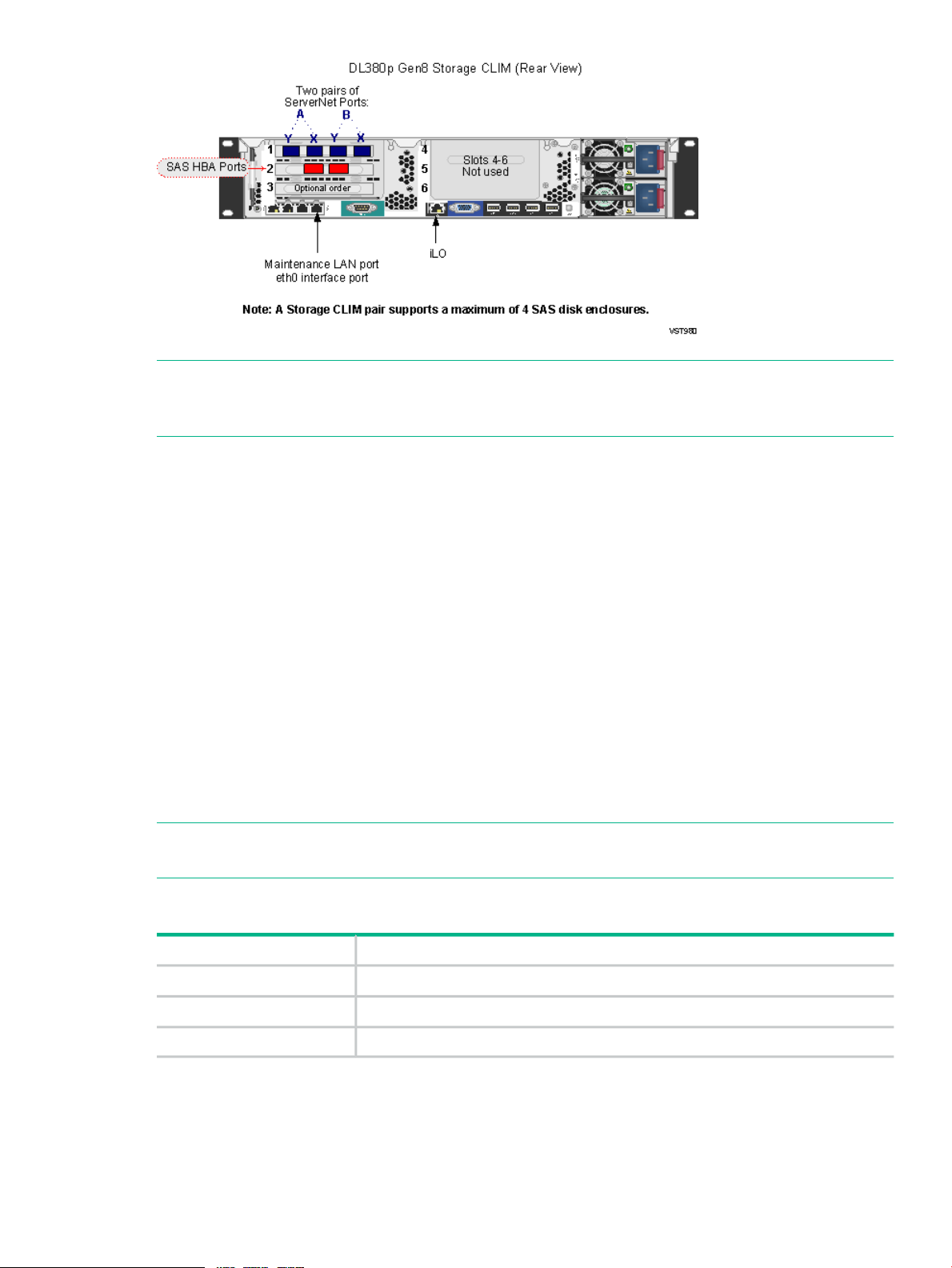
A Storage CLIM pair supports a maximum of 4 SAS disk
enclosures. This maximum applies to G6 and Gen8
Storage CLIM types.
100Maximum SAS disk drives per Storage CLIM pair
2 required (one each for X and Y fabrics)Maximum VIO enclosures
4 embedded Ethernet ports (one port is reserved for OSM)Maximum embedded Ethernet connectivity per VIO
enclosure
4 optional expanded Ethernet ports (copper/optical)Maximum expanded Ethernet connectivity per VIO
enclosure (optional)
SupportedEnterprise Storage System (ESS) support available
through Storage CLIM
Not supportedM8201R Fibre Channel to SCSI router support
Not supportedI/O Adapter Module (IOAM) enclosures
Not supportedFibre Channel disk modules (FCDMs)
Not supportedConnection to NonStop ServerNet Clusters
Not supportedConnection to NonStop S-series I/O
1
For information about coexistence limits for IP and Telco CLIMs, see IP and Telco CLIM Coexistence Limits (page 88).
Figure 1 (page 14) shows the rear view of an NS2100 system with four blade elements in a 42U
modular cabinet with the optional extended runtime module (ERM) and UPS for the three-phase
power configuration.
13
Page 14
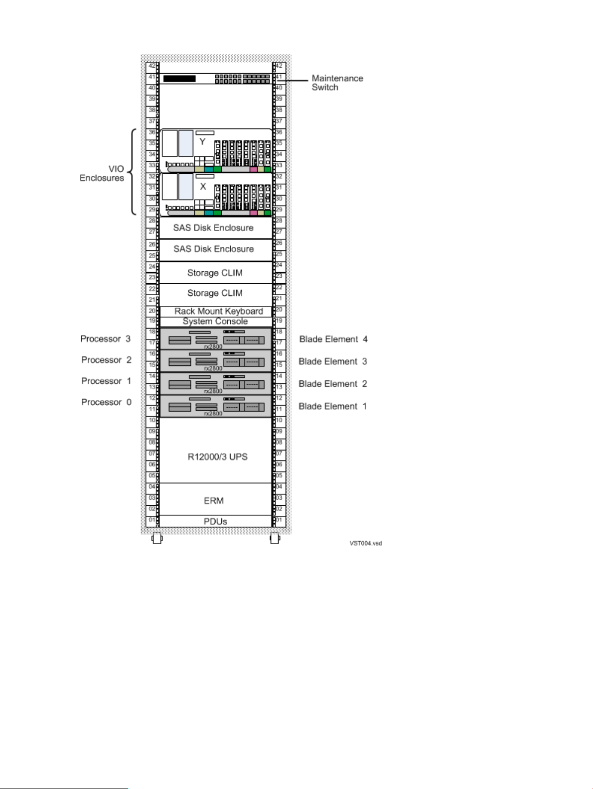
Figure 1 Example of an NS2100 System, 42U
NS2100 Hardware
Some variation of enclosure combinations is possible within the modular cabinets of an NS2100
system. The applications and purpose of any NS2100 system determine the number and
combinations of hardware within a modular cabinet.
Standard Hardware for an NS2100 system includes:
• “Blade Element (rx2800 i2) ” (page 15)
• “Versatile I/O (VIO) Enclosure ” (page 15)
• “Storage CLuster I/O Module (CLIM)” (page 17)
• “SAS Disk Enclosure” (page 24)
14 NS2100 System Overview
Page 15

• “Maintenance Switch ” (page 24)
• “System Console ” (page 24)
Optional Hardware for an NS2100 system includes:
• “IP CLuster I/O Module (CLIM) (Optional)” (page 19)
• “CLIM Cable Management Ethernet Patch Panel” (page 23)
• “UPS (Optional)” (page 25)
• “Enterprise Storage System — ESS (Optional)” (page 26)
• “Tape Drive and Interface Hardware (Optional)” (page 27)
All NS2100 system components are field-replaceable units that can only be serviced by service
providers trained by Hewlett Packard Enterprise.
Because of the number of possible configurations, you can calculate the total power consumption,
heat dissipation, and weight of each modular cabinet based on the hardware configuration that
you order from Hewlett Packard Enterprise. For site preparation specifications for the modular
cabinets and the individual enclosures, see Chapter 3 (page 44).
Blade Element (rx2800 i2)
The HPE Integrity rx2800 i2 server is adapted for use as an AC-powered blade element in the
NS2100 system. Each blade element contains an Intel® Itanium® processor with one core
enabled and a ServerNet PCI adapter card to provide connectivity to the ServerNet fabrics.
NOTE: NS2100 blade elements cannot be mixed with NS2200 blade elements in the same
system.
For details about the rx2800 i2 server, see the HPE Integrity rx2800 i2 Server User Service Guide
at:
http://www.hpe.com/support/Integrity_NonStop_rx2800_i2Server_Manuals
An NS2100 system supports up to four blade elements configured in pairs. Because modular
hardware provides flexibility in how hardware is distributed in a rack, up to four blade elements
can be installed in a single footprint.
To reduce ambiguity in identifying proper cable connections to the blade element, an identification
convention uses numbers to refer to each connection. A number such as 1, 2, 3, and 4 identifies
each blade element. These IDs reference the appropriate blade element for proper connection
of cables.
Versatile I/O (VIO) Enclosure
A VIO enclosure, which is 4U, provides Gigabit Ethernet networking and connectivity to the
processors. Two VIO enclosures, one required for each ServerNet fabric, are installed in a 19-inch
rack.
For a description and illustration of the VIO enclosure slot locations, see Figure 3 (page 32).
Each VIO enclosure contains:
• Connectivity for up to four processors, configured in pairs.
• Connectivity for up to four Storage CLuster I/O Modules (CLIMs) configured in pairs and
used to communicate with storage devices such as Serial Attached SCSI (SAS) disk
enclosures or Enterprise Storage System (ESS) disks.
• Up to eight copper/optical Ethernet ports used for Ethernet connectivity. Additional Ethernet
connectivity is available through IP or Telco CLIM connections with up to two IP or Telco
CLIMs.
NS2100 Hardware 15
Page 16
NOTE: For details about how to connect to the embedded or optional expanded Ethernet
ports on the VIO enclosure, ask your Hewlett Packard Enterprise service provider to refer
to the Versatile I/O Manual.
• Two fans to provide the cooling for components inside a VIO enclosure.
• Two power supplies with universal AC input to provide power to the components in a VIO
enclosure.
CLuster I/O Modules (CLIMs)
CLIMs are rack-mounted servers that can function a ServerNet Ethernet or I/O adapters.
The CLIM complies with Internet Protocol version 6 (IPv6), an Internet Layer protocol for
packet-switched networks, and has passed official certification of IPv6 readiness.
NOTE: All CLIMs use the Cluster I/O Protocols (CIP) subsystem. For more information about
the CIP subsystem, see the Cluster I/O Protocols (CIP) Configuration and Management Manual.
Two models of base servers are used for CLIMs. You can determine a CLIM's model by looking
at the label on the back of the unit (behind the cable arm). This label refers to the number as a
“PID,” but it is not the PID of the CLIM. It is the “Number on Label” in Table 1 (page 16) below.
The same number is listed as the part number in OSM. Below is the mapping for CLIM models
and earliest supported RVUs:
Table 1 CLIM Models and RVU Requirements
Earliest Supported RVUBase ServerNumber on LabelModel
J06.14 and later RVUsDL380494329-B21G6
J06.14 and later RVUsDL380p692764-001Gen8
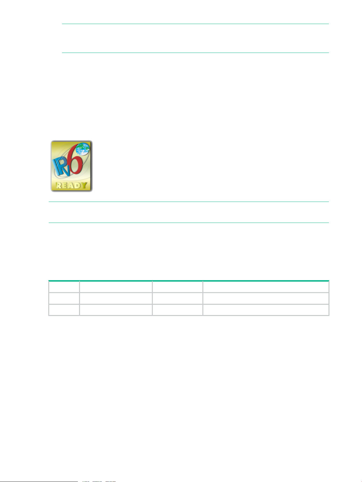
These are the front views of each CLIM model. For an illustration of the back views, refer to each
supported CLIM configuration.
16 NS2100 System Overview
Page 17
These CLIM configurations are supported:
• “Storage CLuster I/O Module (CLIM)” (page 17)
• “IP CLuster I/O Module (CLIM) (Optional)” (page 19)
• “Telco CLuster I/O Module (CLIM) (Optional)” (page 21)
The optional “CLIM Cable Management Ethernet Patch Panel” (page 23) cable management
product is a convenient way to configure Ethernet cables in a NonStop cabinet for IP and Telco
CLIMs.
Storage CLuster I/O Module (CLIM)
The Storage CLuster I/O Module (CLIM) is part of all NS2100 system configurations. For RVU
requirements for DL380 G6 and DL380p Gen8 Storage CLIMs, see Table 1 (page 16). The
Storage CLIM is a rack-mounted server that connects to the VIO enclosure and functions as a
ServerNet I/O adapter providing:
• ServerNet fabric connections.
• A Serial Attached SCSI (SAS) interface for the storage subsystem via a SAS Host Bus
Adapter (HBA) supporting SAS disk drives, solid state drives, and SAS tape devices.
• A Fibre Channel (FC) interface for ESS and FC tape devices via a customer-ordered FC
HBA. A Storage CLIM can have 0, 2, or 4 FC interfaces in an NS2100 system.
Connections to FCDMs are not supported.
DL380 G6 and DL380p Gen8 CLIMs can coexist in the same NS2100 series system; and you
can have G6 and Gen8 CLIM pairs in the same system only if these criteria are met:
• The CLIM pair must be comprised of the same CLIM type (for example, a pair of Gen8
CLIMs). G6 and Gen8 CLIMs cannot coexist within the same CLIM pair.
• Coexisting CLIMs in a system must control different SAS disk enclosures.
NOTE: All CLIMs use the Cluster I/O Protocols (CIP) subsystem. For more information about
the CIP subsystem, see the Cluster I/O Protocols (CIP) Configuration and Management Manual.
Two storage CLIM configurations are available:
• “DL380 G6 Storage CLIM ” (page 18)
• “DL380p Gen8 Storage CLIM ” (page 18)
NS2100 Hardware 17
Page 18
DL380 G6 Storage CLIM
The DL380 G6 Storage CLIM contains 4 PCIe HBA slots with these characteristics:
Storage CLIM
HBA Slot
ProvidesConfiguration
ServerNet fabric connections via a PCIe 4x adapter.Part of base configuration1
Part of base configuration2
One SAS external connector with two SAS links per connector and
6 Gbps per link is provided by the PCIe 8x slot
SAS or Fibre ChannelOptional customer order3
Fibre ChannelOptional customer order4
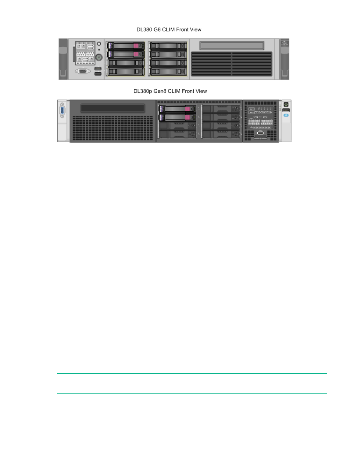
The illustration below shows the Storage CLIM HBA slots. For more information about Storage
CLIMs, see “Storage CLIM Devices” (page 74).
DL380p Gen8 Storage CLIM
The DL380p Gen8 Storage CLIM contains 3 PCIe HBA slots with these characteristics:
Storage CLIM
HBA Slot
2
SAS HBA is part of base
configuration
Optional customer order3
ProvidesConfiguration
ServerNet fabric connections via a PCIe 4x adapter.Part of base configuration1
Two 6 Gbps SAS ports.
NOTE: Fibre Channel HBA is not part of base configuration. An FC
HBA in slot 2 is an optional customer order.
SAS HBA with two 6 Gbps ports or FC HBA with two 8 Gbps ports.
NOTE: Not part of base configuration. Optional customer order.
18 NS2100 System Overview
Page 19
NOTE: The Storage CLIM uses the Cluster I/O Protocols (CIP) subsystem. For more information
about the CIP subsystem, refer to the Cluster I/O Protocols (CIP) Configuration and Management
Manual.
IP CLuster I/O Module (CLIM) (Optional)
The IP CLIM is a rack-mounted server that is part of some NS2100 system configurations. For
RVU requirements for DL380 G6 and DL380p Gen8 IP CLIMs, see Table 1 (page 16). An NS2100
system can have 0, 1, or 2 IP CLIMs. The IP CLIM connects to the VIO enclosure and functions
as a ServerNet Ethernet adapter providing HPE standard Gigabit Ethernet Network Interface
Cards (NICs) to implement one of these IP CLIM configurations:
• “DL380 G6 IP CLIM Option 1 — Five Ethernet Copper Ports” (page 19)
• “DL380 G6 IP CLIM Option 2 — Three Ethernet Copper and Two Ethernet Optical Ports”
(page 20)
• “DL380p Gen8 IP CLIM Option 1 — Five Ethernet Copper Ports” (page 20)
• “DL380p Gen8 IP CLIM Option 2 — Three Ethernet Copper and Two Ethernet Optical Ports”
(page 21)
These illustrations show the Ethernet interfaces and ServerNet fabric connections on the DL380
G6 and DL380p Gen8 IP CLIM with the IP CLIM option 1 and option 2 configurations. For
illustrations of the fronts of these CLIMs, see “CLuster I/O Modules (CLIMs)” (page 16).
NOTE: All CLIMs use the Cluster I/O Protocols (CIP) subsystem. For more information about
the CIP subsystem, see the Cluster I/O Protocols (CIP) Configuration and Management Manual.
DL380 G6 IP CLIM Option 1 — Five Ethernet Copper Ports
ProvidesIP CLIM Slot
ServerNet fabric connections via a PCIe 4x adapterSlot 1
2-port 1GbE copper NICSlot 2
Not usedSlots 3, 4, 5
NS2100 Hardware 19
Page 20
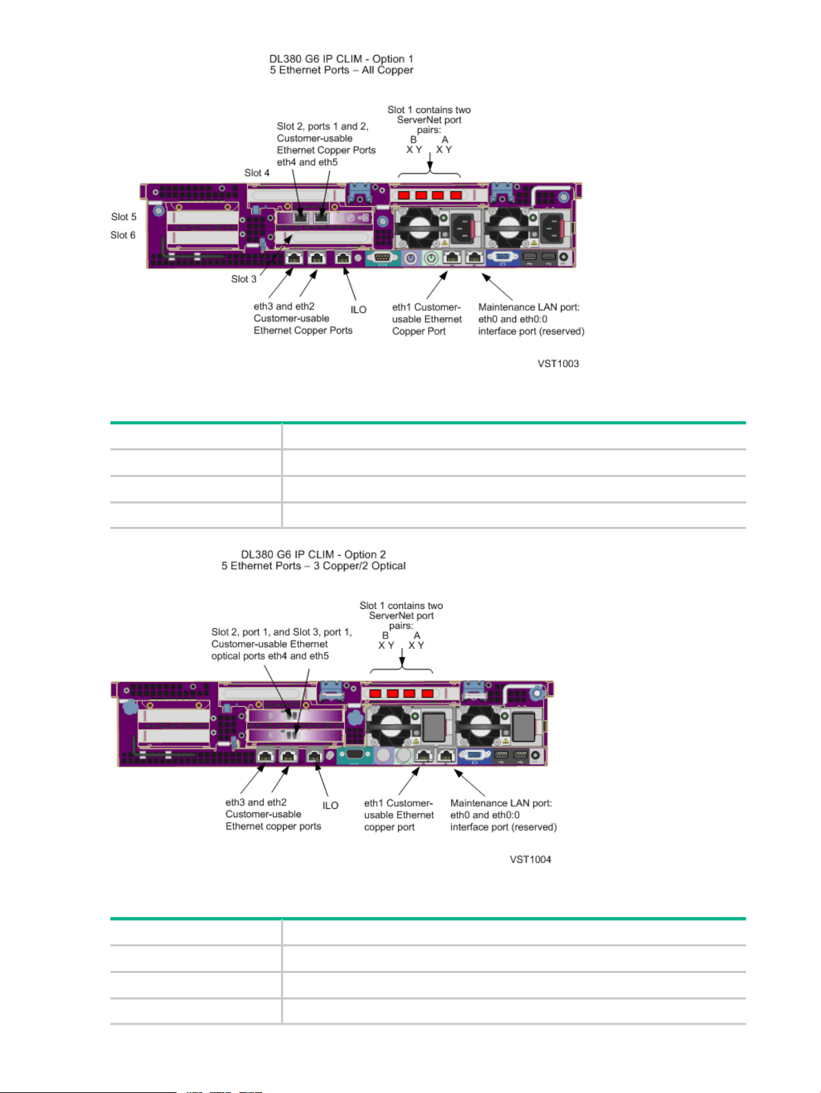
DL380 G6 IP CLIM Option 2 — Three Ethernet Copper and Two Ethernet Optical Ports
ProvidesIP CLIM Slot
ServerNet fabric connections via a PCIe 4x adapterSlot 1
1-port 1GbE optical NICSlot 2 and Slot 3
Not usedSlot 4 and Slot 5
DL380p Gen8 IP CLIM Option 1 — Five Ethernet Copper Ports
20 NS2100 System Overview
ProvidesIP CLIM Slot
One ServerNet PCIe interface card, which provides the ServerNet fabric connectionsSlot 1
2-port 1GbE copper NICSlot 2
Not usedSlots 3, 4, 5, 6
Page 21

DL380p Gen8 IP CLIM Option 2 — Three Ethernet Copper and Two Ethernet Optical Ports
ProvidesIP CLIM Slot
One ServerNet PCIe interface card, which provides the ServerNet fabric connectionsSlot 1
2-port 1GbE optical NICSlot 2
Not usedSlots 3, 4, 5, 6
Telco CLuster I/O Module (CLIM) (Optional)
The Telco CLIM is a rack-mounted server that is part of some NS2100 series system
configurations. For RVU requirements for DL380 G6 and DL380p Gen8 Telco CLIMs, see Table 1
(page 16). An NS2100 series system can have 0, 1, or 2 Telco CLIMs. For information about
coexistence limits for IP and Telco CLIMs, see IP and Telco CLIM Coexistence Limits (page 88).
The Telco CLIM connects to the VIO enclosure and utilizes the Message Transfer Part Level 3
User Adaptation layer (M3UA) protocol and functions as a ServerNet Ethernet adapter with one
of these Telco CLIM configurations:
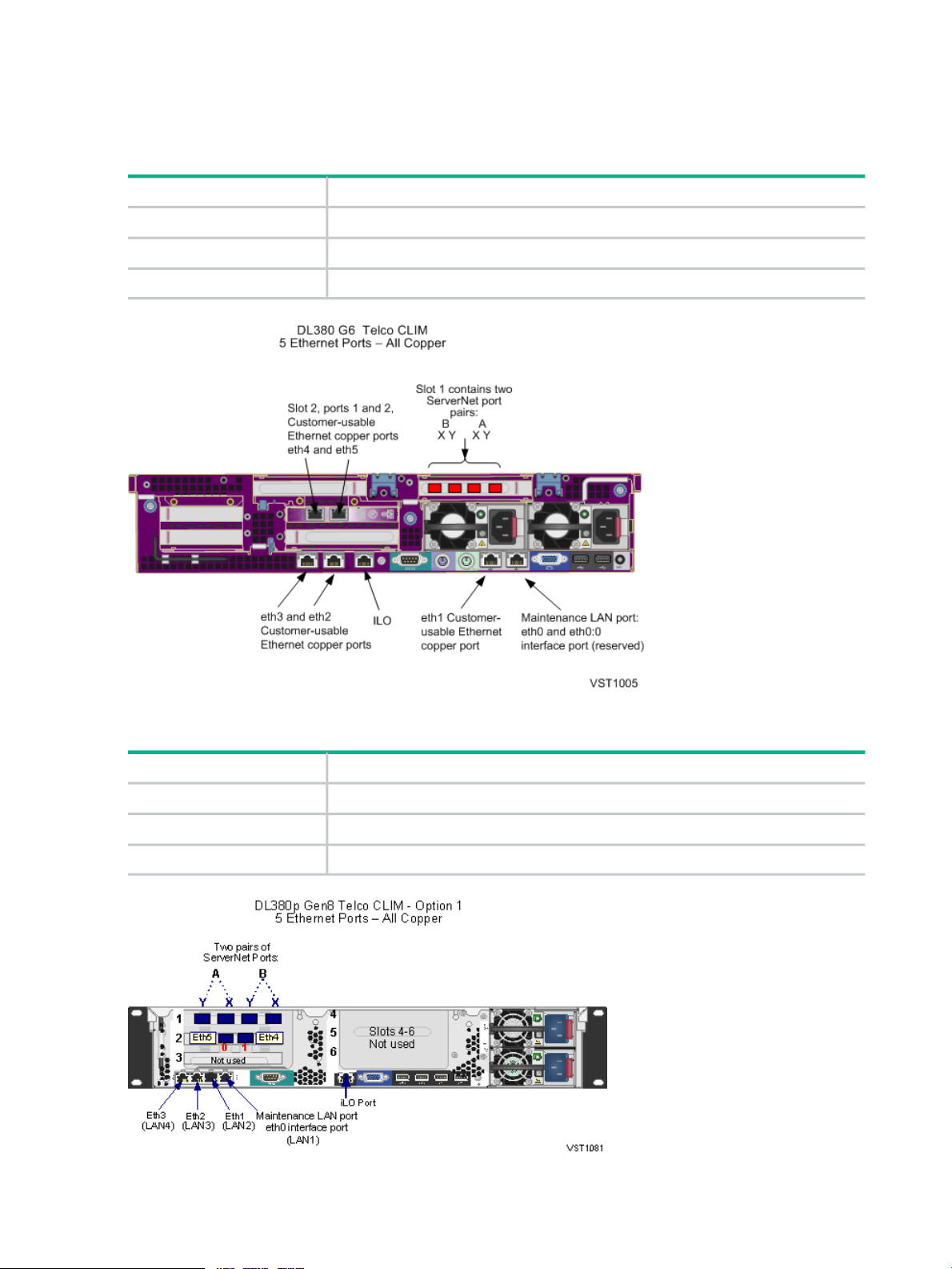
• “DL380 G6 Telco CLIM — Five Ethernet Copper Ports” (page 22)
• “DL380p Gen8 Telco CLIM — Option 1 Five Ethernet Copper Ports” (page 22)
• “DL380p Gen8 Telco CLIM — Option 2 Three Ethernet Copper and Two Ethernet Optical
Ports” (page 23)
NOTE: All CLIMs use the Cluster I/O Protocols (CIP) subsystem. For more information about
the CIP subsystem, see the Cluster I/O Protocols (CIP) Configuration and Management Manual.
NS2100 Hardware 21
Page 22
This illustration shows the Ethernet interfaces and ServerNet fabric connections on a DL380 G6
and DL380p Gen8 Telco CLIM. For illustrations of the front of this CLIM, see “CLuster I/O Modules
(CLIMs)” (page 16).
DL380 G6 Telco CLIM — Five Ethernet Copper Ports
ProvidesTelco CLIM Slot
ServerNet fabric connections via a PCIe 4x adapterSlot 1
2-port 1GbE copper NICSlot 2
Not usedSlots 3, 4, 5
DL380p Gen8 Telco CLIM — Option 1 Five Ethernet Copper Ports
ProvidesTelco CLIM Slot
One ServerNet PCIe interface card, which provides the ServerNet fabric connectionsSlot 1
2-port 1GbE copper NICSlot 2
Not usedSlots 3, 4, 5, 6
22 NS2100 System Overview
Page 23
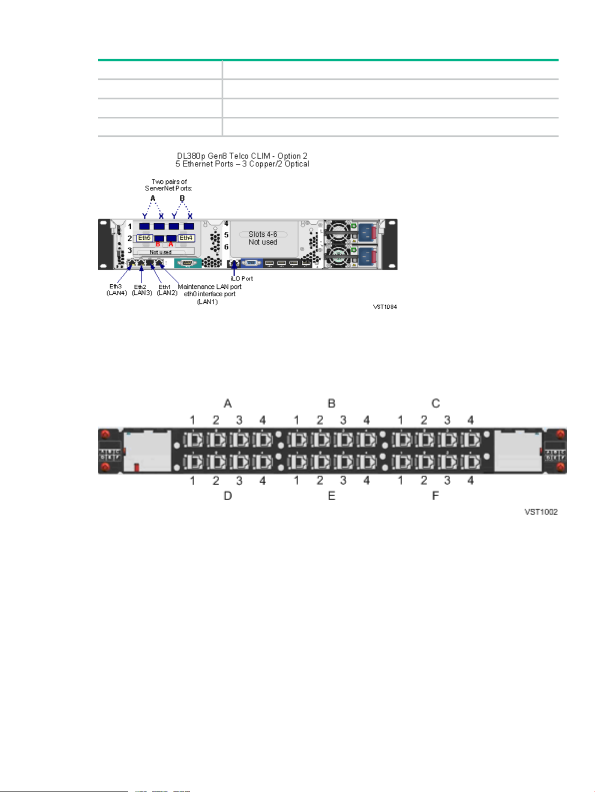
DL380p Gen8 Telco CLIM — Option 2 Three Ethernet Copper and Two Ethernet Optical Ports
ProvidesTelco CLIM Slot
One ServerNet PCIe interface card, which provides the ServerNet fabric connectionsSlot 1
2-port 1GbE optical NICSlot 2
Not usedSlot 3, 4, 5, 6
CLIM Cable Management Ethernet Patch Panel
The HPE Ethernet patch panel cable management product is used for cabling the IP and Telco
CLIM connections. The patch panel simplifies and organizes the cable connections to allow easy
access to the CLIM's customer-usable interfaces.
IP CLIMs each have five customer-usable interfaces. The patch panel connects these interfaces
and brings the usable interface ports to the patch panel. Each Ethernet patch panel has 24 slots,
is 1U high, and should be the topmost unit to the rear of the rack. Each Ethernet patch panel can
handle cables for up to five CLIMs. It has no power connection.
Each patch panel has 6 panes labeled A, B, C, D, E, and F. Each pane has 4 RJ-45 ports, and
each port is labeled 1, 2, 3, or 4. The RJ-45 ports in Panel A have port names: A1, A2, A3, and
A4.
The factory default configuration depends on how many IP or Telco CLIMs and patch panels are
configured in the system. For a new system, QMS Tech Doc generates a cable table with the
CLIM interface name. This table identifies how the connections between the CLIM physical ports
and patch panel ports were configured at the factory.
If you are adding a patch panel to an existing system, ask your Hewlett Packard Enterprise
service provider to refer to the CLuster I/O (CLIM) Installation and Configuration Guide.
NS2100 Hardware 23
Page 24

SAS Disk Enclosure
The M8381-25 SAS disk enclosure is a rack-mounted disk enclosure that connects to the Storage
CLIM and supports up to 25 SAS disk drives or solid state drives (in any combination), and a
dual SAS domain from the Storage CLIMs to dual port SAS drives. The SAS disk enclosure
supports connections to SAS disk drives. Connections to FCDMs are not supported. You can
find more information about the M8381-25 SAS disk enclosure in the HPE StorageWorks
D2600/D2700 Disk Enclosure User Guide.
NOTE: Solid state drives are supported as of J06.13.
An M8381-25 SAS disk enclosure supports 6Gbps SAS protocol. It contains:
• Twenty-five 2.5” dual-ported disk drive slots
• Two power supplies
• Two fans
• Two independent I/O modules:
SAS Domain A◦
◦ SAS Domain B
For illustrations of the SAS disk enclosure, see Figure 20 (page 76).
Maintenance Switch
The HPE ProCurve maintenance switch provides the communication between the NS2100 system
through the VIO enclosures, CLIMs, the optional UPS, and the system console running HPE
NonStop Open System Management (OSM).
The NS2100 system requires multiple connections to the maintenance switch:
• One connection from the ME ENET port on each of the two VIO enclosures
• One connection from slot 6B, port A on each of the two VIO enclosures for the OSM Service
Connection and OSM Notification Director (optional if a dedicated service LAN is implemented
using CLIMs)
• One connection to the iLO port on a CLIM
• One connection to the iLO port on a blade element
• One connection to an eth0 port on a CLIM
• One connection to the optional UPS module
• One connection to the system console running OSM
System Console
A system console is a Windows Server purchased from Hewlett Packard Enterprise that runs
maintenance and diagnostic software for NS2100 systems. When supplied with a new NS2100
system, system consoles have factory-installed Hewlett Packard Enterprise and third-party
software for managing the system. You can install software upgrades from the HPE NonStop
System Console Installer DVD.
Some system console hardware, including the Windows Server system unit, monitor, and
keyboard, can be mounted in the NS2100 system 19-inch rack. Other Windows Servers are
installed outside the rack and require separate provisions or furniture to hold the server hardware.
For more information on the system console, see “System Consoles for NS2100 Systems ”
(page 101).
24 NS2100 System Overview
Page 25

UPS (Optional)
An uninterruptible power supply (UPS) is optional but recommended where a site UPS is not
available.
A UPS can be combined with an extended runtime module (ERM) to extend battery run time.
See “ERM (Optional with UPS)” (page 26).
Depending on your power configuration, Hewlett Packard Enterprise supports these options:
• “UPS for a Single-Phase Power Configuration (Optional)” (page 25)
• “UPS for a Three-Phase Power Configuration (Optional)” (page 25)
WARNING! UPSs and ERMs must be mounted in the lowest portion of the system to avoid
tipping and stability issues. For more information, see the UPS user guide.
UPS for a Single-Phase Power Configuration (Optional)
Hewlett Packard Enterprise supports the HPE model R5000 UPS for the single-phase power
configuration because it utilizes the power fail support provided by OSM for this configuration.
For information about the requirements for installing a UPS, see “Uninterruptible Power Supply
(UPS)” (page 40).
There are two different versions of the R5000 single phase UPS:
• For North America and Japan, the HPE AF460A is utilized and uses a NEMA L6-30P (30A)
input connector with 200 to 208V single-phase.
• For International, the HPE AF461A is utilized and uses an IEC-60309 (32A) input connector
with 220V to 240V AC single-phase power.
NOTE: The AC input power cord for the single-phase UPS is routed to exit the modular cabinet
at either the top or bottom rear corners of the cabinet, depending on what is ordered for the site
power feed (the large output receptacle is unused).
For the UPS power and environmental requirements, see “System Installation Specifications for
NS2100 Systems” (page 44). For planning, installation, and emergency power-off (EPO)
instructions, see the HPE UPS R5000 User Guide and the HPE UPS Network Module User Guide
at http://www.hpe.com/support/UPS_3_Phase_Manuals
For other UPSs, see the documentation shipped with the UPS.
UPS for a Three-Phase Power Configuration (Optional)
Hewlett Packard Enterprise supports the HPE model R12000/3 UPS for the three-phase power
configuration because it utilizes the power fail support provided by OSM for this configuration.
For information about the requirements for installing a UPS, see “Uninterruptible Power Supply
(UPS)” (page 40).
There are two different versions of the R12000/3 UPS:
• For North America and Japan, the HPE AF429A is utilized and uses an IEC309 560P9 (60A)
input connector with 208V three-phase Wye.
• For International, the HPE AF430A is utilized and uses an IEC309 532P6 (32A) input
connector with 400V three-phase Wye.
NOTE: The R12000/3 UPS has two output connectors.
For the R12000/3 UPS power and environmental requirements, see Chapter 3 (page 44). For
planning, installation, and emergency power-off (EPO) instructions, see the HPE 3 Phase UPS
User Guide. This guide is on the Hewlett Packard Enterprise website at:
http://www.hpe.com/support/UPS_3_Phase_Manuals
NS2100 Hardware 25
Page 26

For other UPSs, see the documentation shipped with the UPS.
ERM (Optional with UPS)
Cabinet configurations that include the HPE UPS can also include extended runtime modules
(ERMs). An ERM is a battery module that extends the overall battery-supported system run time.
Up to two ERMs can be used for even longer battery-supported system run time.
Enterprise Storage System — ESS (Optional)
An Enterprise Storage System (ESS) is a collection of magnetic disks, their controllers, and a
disk cache in one or more standalone cabinets. ESS connects to the Integrity NonStop NS-series
systems either directly via Fibre Channel ports on the Storage CLIM (direct connect) or through
a separate storage area network (SAN) using a Fibre Channel SAN switch (switched connect).
For more information about these connection types, see your Hewlett Packard Enterprise service
provider.
NOTE: The Fibre Channel SAN switch power cords might not be compatible with the modular
cabinet PDU. Contact your Hewlett Packard Enterprise service provider to order replacement
power cords for the SAN switch that are compatible with the modular cabinet PDU.
Cables and switches vary, depending on whether the connection is direct, switched, or a
combination:
Fibre Channel SwitchesCablesConnection
Direct connect
on Storage CLIM (LC-MMF)
Switched
CLIM (LC-MMF)
Combination of direct and switched
CLIM for each direct connection
CLIM for each switched connection
1
Customer must order FC HBA interfaces for a pair of Storage CLIMs.
1
02 Fibre Channel (FC) HBA interfaces
1 or more4 FC HBA interfaces on Storage
12 FC HBA interfaces on Storage
14 FC HBA interfaces on Storage
Figure 2 shows an example of connections between two Storage CLIMs and an ESS via separate
Fibre Channel switches:
26 NS2100 System Overview
Page 27
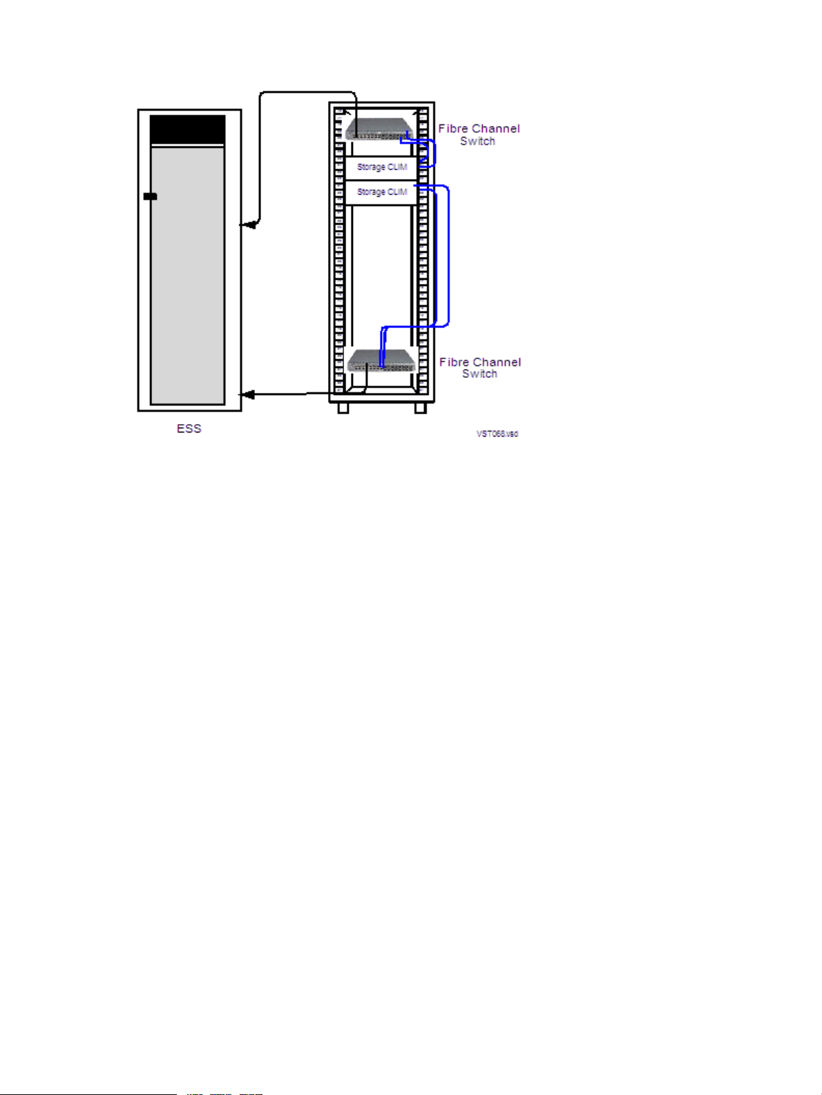
Figure 2 Connections Between Storage CLIMs and ESS
For fault tolerance, the primary and backup paths to an ESS logical device (LDEV) must go
through different Fibre Channel switches.
Some storage area procedures, such as reconfiguration, can cause the affected switches to
pause. If the pause is long enough, I/O failure occurs on all paths connected to that switch. If
both the primary and the backup paths are connected to the same switch, the LDEV goes down.
For more information, see the documentation that accompanies the ESS.
Tape Drive and Interface Hardware (Optional)
For an overview of tape drives and the interface hardware, see “Fibre Channel Ports to Tape
Devices” (page 74) and “SAS Ports to SAS Tape Devices” (page 74).
For a list of supported tape devices, ask your Hewlett Packard Enterprise service provider to
refer to the NonStop Storage Overview.
Preparation for Other Hardware
This guide provides the specifications only for the NS2100 system modular cabinets and
enclosures identified earlier in this section. For site preparation specifications for other Hewlett
Packard Enterprise hardware that will be installed at the site with the NS2100 systems, consult
with your Hewlett Packard Enterprise account team. For site preparation specifications relating
to hardware from other manufacturers, refer to the documentation for those devices.
Component Location and Identification in an NS2100 System
This subsection includes these topics:
• “Terminology” (page 28)
• “Rack and Offset Physical Location ” (page 29)
• “Blade Element Group-Module-Slot Numbering ” (page 29)
• “VIO Enclosure Group-Module-Slot Numbering ” (page 31)
• “CLIM Connection Group-Module-Slot-Port Numbering ” (page 33)
Preparation for Other Hardware 27
Page 28

Terminology
These are terms used in locating and describing components in an NS2100 commercial system:
DefinitionTerm
Cabinet
Rack
Rack Offset
Group
Module
Slot (or Bay or Position)
Port
• Group-Module-Slot (GMS)
• Group-Module-Slot-Bay (GMSB)
• Group-Module-Slot-Port (GMSP)
Computer system housing that includes a structure of
external panels, front and rear doors, internal racking,
and dual PDUs.
Structure integrated into the cabinet into which
rack-mountable components are assembled.
The physical location of components installed in a modular
cabinet, measured in U values numbered 1 to 42, with 1U
at the bottom of the cabinet. A U is 1.75 inches (44
millimeters).
A subset of a system that contains one or more modules.
A group does not necessarily correspond to a single
physical object, such as an enclosure.
A subset of a group that is usually contained in an
enclosure. A module contains one or more slots (or bays).
A module can consist of components sharing a common
interconnect, such as a backplane, or it can be a logical
grouping of components performing a particular function.
A subset of a module that is the logical or physical location
of a component within that module.
A connector to which a cable can be attached and which
transmits and receives data.
A notation method used by hardware and software in
NonStop systems for organizing and identifying the
location of certain hardware components.
Blade complex
rx2800 i2 blade element
In an NS2100 system, OSM uses this term to
hierarchically differentiate between each blade element.
An HPE Integrity rx2800 i2 server that contains the
processor element, power supplies, fan assemblies, and
firmware. An NS2100 system includes up to four blade
elements.
On NS2100 systems, locations of the modular components are identified by:
• Physical location:
Rack number◦
◦ Rack offset
• Logical location:
◦ Group, module, and slot (GMS) notation as defined by their position on the ServerNet
rather than the physical location
OSM uses GMS notation in many places, including the Tree view and Attributes window, and it
uses rack and offset information to create displays of the server and its components. For example,
in the Tree view, OSM displays the location of a power supply in a VIO enclosure in group 100,
module 2, slot 15 in this form:
Power Supply (100.2.15)
28 NS2100 System Overview
Page 29

Rack and Offset Physical Location
Rack name and rack offset identify the physical location of components in an NS2100 system.
The rack name is located on an external label affixed to the rack, which includes the system
name plus a 2-digit rack number.
Rack offset is labeled on the rails in each side of the rack. These rails are measured vertically
in units called U, with one U measuring 1.75 inches (44 millimeters). The rack is 36U with 1U
located at the bottom and 36U at the top or 42U with 1U located at the bottom and 42U at the
top. The rack offset is the lowest number on the rack that the component occupies.
Blade Element Group-Module-Slot Numbering
• Group:
In OSM Service Connection displays, 400 through 403 relates to blade complexes 0
◦
through 4. Each blade complex includes a blade element and its associated processor.
Example: group 403 = blade complex 3
◦ In the OSM Low-Level Link, 400 relates to all blade complexes.
Example: group 400 = any blade complex
• Module:
In OSM Service Connection displays, a module represents either the blade element or
◦
the processor:
– In an NS2100 system, all blade elements are module 1.
Example: module 1 = any blade element
– 100-103 relates to processors 0-3
Example: module 102 = processor 2
◦ In the OSM Low-Level Link, 100 through 103 relates to processors 0 through 3.
Example: module 103 = processor 3
• Slot:
In OSM Service Connection displays:◦
– 1 represents the ServerNet PCI adapter card.
The ServerNet PCI card is installed in the third PCI slot in the rx2800 i2.
– 3 and 4 represent the power supplies on the blade element.
OSM slot 3 represents power supply 1; OSM slot 4 represents power supply 2.
– 32 through 37 represent the fans on the blade element.
OSM slot 32 represents fan 1, OSM slot 33 represents fan 2, and so on.
◦ In the OSM Low-Level Link, 1 relates to the location of the processor. Because each
blade element contains only one processor, it is always located in slot 1.
Example: slot 1 = any processor in any blade element.
• Port: X and Y relate to the two ServerNet fabric ports in slot 1.
These tables show the default numbering for the blade elements of an NS2100 system when
blade elements are powered on and functioning:
Component Location and Identification in an NS2100 System 29
Page 30

NOTE: In OSM, if a blade element is not present or is powered off, processors might be
renumbered. For example, if processor 2 has been removed, processor 3 becomes processor
2 in OSM displays.
GMS Numbering Displayed in the OSM Service Connection:
Port (Slot 2 only)SlotModuleGroup*Processor
ID
ProcessorBlade
Element
10014000
10114011
10214022
10314033
*In OSM, the term Blade Complex is used for the group.
GMS Numbering Displayed in the OSM Low-Level Link:
*In OSM, the term Blade Complex is used for the group.
(physical PCI slot 1)
3-4, power supplies.
(physical power supplies 1
and 2)
32—37, fans (physical fans
1 through 6)
X1, PCI adapter card.
Y
SlotModuleGroup*Processor ID
11004000
11014001
11024002
11034003
The form of the GMS numbering for a blade element displayed in the OSM Service Connection
is:
This illustration shows the physical GMS numbering for the rear view of a blade element:
30 NS2100 System Overview
Page 31

The X fabric connects to ports BX and AX. The Y fabric connects to ports BY and AY.
VIO Enclosure Group-Module-Slot Numbering
An NS2100 system supports a single pair of VIO enclosures, identified as group 100. For an
illustration of the VIO enclosure slots, see Figure 3 (page 32).
SlotModuleGroup
PortsItemVIO Enclosure (AC-Powered)
X
Fabric
Y
Fabric
Displayed by
OSM
6
Displayed on
Chassis
6a6
1
6b
7a7
7b7
Storage CLIM33
Ethernet ports
(optical)
(copper)
(optical)
(copper)
-Not supported1132100
-Not supported22
1 and 3 for 2 Storage
CLIMs; 1 - 4 for 4 Storage
CLIMs
1 - 2IP CLIM44
1 - 2Telco CLIM
-Not supported55
C and D (10/100/1000
Mbps)
A , B (10/100 Mbps)Ethernet ports
C, D (10/100/1000 Mbps)
C, D (10/100/1000 Mbps)Ethernet ports
A , B (10/100 Mbps)Ethernet ports
C, D (10/100/1000 Mbps)
-Not supported7c7
14.1 - 14.414
(processors 0-3)
Component Location and Identification in an NS2100 System 31
1 - 4Processor ports
-Power supplies15, 1815, 18
-Fans16, 1716, 17
Page 32

1
Port A in slot 6b is reserved for OSM.
Figure 3 VIO Enclosure Slot Locations, NS2100 System
32 NS2100 System Overview
Page 33

CLIM Connection Group-Module-Slot-Port Numbering
This table lists the default numbering for VIO connections to a CLIM:
PIC Port NumbersVIO SlotModuleCLIM Group
3 (Storage CLIM)2100
4 (Telco CLIM)
3 (Storage CLIM)3100
4 (Telco CLIM)
1 and 3 for 2 Storage CLIMs,
1 - 4 for 4 Storage CLIMs
1-24 (IP CLIM)
1 and 3 for 2 Storage CLIMs,
1 - 4 for 4 Storage CLIMs
1-24 (IP CLIM)
The illustration below shows the slot and connector locations from the VIO modules to two DL380
G6 Storage CLIMs.
Figure 4 DL380 G6 Storage CLIM Connections to VIO Enclosures
Component Location and Identification in an NS2100 System 33
Page 34

The illustration below shows the slot and connector locations from the VIO modules to two DL380
G6 IP or Telco CLIMs.
NOTE: The Telco CLIM connections are the same as the IP CLIM connections.
Figure 5 DL380 G6 IP or Telco CLIM Connections to VIO Enclosures
34 NS2100 System Overview
Page 35

The illustration below shows the slot and connector locations from the VIO modules to two DL380p
Gen8 Storage CLIMs.
Figure 6 DL380p Gen8 Storage CLIM Connections to VIO Enclosures
Component Location and Identification in an NS2100 System 35
Page 36

The illustration below shows the slot and connector locations from the VIO modules to two DL380p
Gen8 IP or Telco CLIMs.
NOTE: The Telco CLIM connections are the same as the IP CLIM connections.
Figure 7 DL380p Gen8 IP or Telco CLIM Connections to VIO Enclosures
System Installation Document Packet
To keep track of the hardware configuration, internal and external communications cabling, IP
addresses, and connect networks, assemble and retain as the systems records an Installation
Document Packet. This packet can include:
• “Tech Memo for the Factory-Installed Hardware Configuration ” (page 36)
• “Configuration Forms for the CLIMs and ServerNet Adapters ” (page 37)
Tech Memo for the Factory-Installed Hardware Configuration
Each new NS2100 system includes a document that describes:
• The cabinet included with the system
• Each hardware enclosure installed in the cabinet
• Cabinet U location of the bottom edge of each enclosure
• Each ServerNet cable with:
Source and destination enclosure, component, and connector◦
◦ Cable part number
◦ Source and destination connection labels
36 NS2100 System Overview
Page 37

This document is called a tech memo and serves as the physical location and connection map
for the system.
Configuration Forms for the CLIMs and ServerNet Adapters
Ethernet ports on a VIO enclosure or connections to an IP or Telco CLIM provide Gigabit Ethernet
functionality in an NS2100 system. Connections to the Fibre Channel HBA interfaces on a Storage
CLIM provide the Fibre Channel functionality in the system.
To add Fibre Channel and Ethernet configuration forms to your Installation Document Packet,
ask your Hewlett Packard Enterprise service provider to provide the necessary forms from the
Versatile I/O Manual or the Cluster I/O Installation and Configuration Manual (for IP or Telco
CLIM-related configurations) and follow any associated planning instructions.
System Installation Document Packet 37
Page 38

2 Site Preparation Guidelines for NS2100 Systems
This section describes power, environmental, and space considerations for an NS2100 system
at your site.
Modular Cabinet Power and I/O Cable Entry
Power and I/O cables can enter the NS2100 system from either the top or the bottom rear of the
modular cabinets, depending on how the cabinets are ordered from Hewlett Packard Enterprise
and the routing of the AC power feeds at the site. NS2100 system cabinets can be ordered with
the AC power cords for the PDUs exiting either:
• Top: Power and I/O cables are routed from above the modular cabinet.
• Bottom: Power and I/O cables are routed from below the modular cabinet
For information about modular cabinet power and cable options, refer to “AC Input Power for
Modular Cabinets” (page 58).
Emergency Power-Off (EPO)
This section describes these EPO topics:
• “EPO Switches” (page 38)
• “EPO Requirement for NS2100 Systems” (page 38)
• “EPO Requirement for HPE R5000 UPS” (page 38)
• “EPO Requirement for HPE R12000/3 UPS” (page 38)
EPO Switches
EPO switches are required by local codes or other applicable regulations when computer
equipment contains batteries capable of supplying more than 750 volt-amperes (VA) for more
that five minutes. Systems that have these batteries also have internal EPO hardware for
connection to a site EPO switch or relay. In an emergency, activating the EPO switch or relay
removes power from all electrical equipment in the computer room (except that used for lighting
and fire-related sensors and alarms).
EPO Requirement for NS2100 Systems
NS2100 systems without an optional UPS (such as an HPE R5000 UPS) installed in the modular
cabinet do not contain batteries capable of supplying more than 750 volt-amperes (VA) for more
that five minutes, so they do not require connection to a site EPO switch.
EPO Requirement for HPE R5000 UPS
The rack-mounted HPE R5000 UPS is supported for a single-phase power configuration. The
UPS contains batteries, has an EPO circuit, and can be optionally installed in a modular cabinet.
For site EPO switches or relays, consult your Hewlett Packard Enterprise site preparation specialist
or electrical engineer regarding requirements.
If an EPO switch or relay connector is required for your site, contact your Hewlett Packard
Enterprise representative or see the HPE UPS R5000 User Guide at http://www.hpe.com/support/
UPS_3_Phase_Manuals
EPO Requirement for HPE R12000/3 UPS
The rack-mounted HPE R12000/3, UPS is supported for a three-phase power configuration. This
UPS contains batteries, has a remote EPO (REPO) port, and can be optionally installed in a
38 Site Preparation Guidelines for NS2100 Systems
Page 39

modular cabinet. For site EPO switches or relays, consult your Hewlett Packard Enterprise site
preparation specialist or electrical engineer regarding requirements.
If an EPO switch or relay connector is required for your site, contact your Hewlett Packard
Enterprise representative or see the HPE 3 Phase UPS User Guide for connectors and wiring
for the HPE R12000/3 UPS. This guide is on the Hewlett Packard Enterprise website at:
http://www.hpe.com/support/UPS_3_Phase_Manuals
Electrical Power and Grounding Quality
Proper design and installation of a power distribution system for an NS2100 system requires
specialized skills, knowledge, and understanding of appropriate electrical codes and the limitations
of the power systems for computer and data processing equipment. For power and grounding
specifications, see “AC Input Power for Modular Cabinets” (page 58).
Power Quality
This equipment is designed to operate reliably over a wide range of voltages and frequencies,
described in “Enclosure AC Input” (page 60). However, damage can occur if these ranges are
exceeded. Severe electrical disturbances can exceed the design specifications of the equipment.
Common sources of such disturbances are:
• Fluctuations occurring within the facility’s distribution system
• Utility service low-voltage conditions (such as sags or brownouts)
• Wide and rapid variations in input voltage levels
• Wide and rapid variations in input power frequency
• Electrical storms
• Large inductive sources (such as motors and welders)
• Faults in the distribution system wiring (such as loose connections)
Computer systems can be protected from the sources of many of these electrical disturbances
by using:
• A dedicated power distribution system
• Power conditioning equipment
• Lightning arresters on power cables to protect equipment against electrical storms
For steps to take to ensure proper power for the servers, consult with your Hewlett Packard
Enterprise site preparation specialist or power engineer.
Grounding Systems
The site building must provide a power distribution safety ground/protective earth for each AC
service entrance to all NonStop server equipment. This safety grounding system must comply
with local codes and any other applicable regulations for the installation locale.
For proper grounding/protective earth connection, consult with your Hewlett Packard Enterprise
site preparation specialist or power engineer.
Power Consumption
In an NS2100 system, the power consumption and inrush currents per connection can vary
because of the unique combination of enclosures housed in the modular cabinet. Thus, the total
power consumption for the hardware installed in the cabinet should be calculated as described
in “Enclosure Power Loads” (page 60).
Electrical Power and Grounding Quality 39
Page 40

Uninterruptible Power Supply (UPS)
NOTE: An NS2100 system supports the HPE model R5000 UPS for a single-phase power
configuration and the HPE model R12000/3 UPS for a three-phase power configuration. An
extended run-time module (ERM) can be combined with a UPS to extend battery time.
Modular cabinets do not have built-in batteries to provide power during power failures. To support
system operation and ride-through support during a power failure, NS2100 systems require either
an optional UPS installed in each modular cabinet or a site UPS to support system operation
through a power failure. This system operation support can include a planned orderly shutdown
at a predetermined time in the event of an extended power failure. A timely and orderly shutdown
prevents an uncontrolled and asymmetric shutdown of the system resources from depleted UPS
batteries.
OSM provides this ride-through support during a power failure. When OSM detects a power
failure, it triggers a ride-through timer. To set this timer, you must configure the ride-through time
in SCF. For this information, see the SCF Reference Manual for the Kernel Subsystem. If AC
power is not restored before the configured ride-through time period ends, OSM initiates an
orderly shutdown of I/O operations and processors. For additional information, see “AC Power
Monitoring” (page 62).
NOTE: Retrofitting a system in the field with a UPS or a UPS/ERM combination will likely
require moving all installed enclosures in the rack to provide space for the new hardware. One
or more of the enclosures that formerly resided in the rack might be displaced and therefore have
to be installed in another rack that would also need a UPS or UPS/ERM combination installed.
Additionally, lifting equipment might be required to lift heavy enclosures to their new location.
For information and specifications on the UPS and ERM that is supported for a single-phase
power configuration, see Chapter 3 (page 44) and the HPE UPS R5000 User Guide at:
http://www.hpe.com/support/UPS_3_Phase_Manuals
For information and specifications on the R12000/3 UPS and ERM that is supported for a
three-phase power configuration, see Chapter 3 (page 44) and the HPE 3 Phase UPS User
Guide at:
http://www.hpe.com/support/UPS_3_Phase_Manuals
If you install a UPS other than the HPE model R5000 or R12000/3 UPS in each modular cabinet
of an NS2100 system, these requirements must be met to ensure the system can survive a total
AC power fail:
• The UPS output voltage can support the HPE PDU input voltage requirements.
• The UPS phase output matches the PDU phase input. For information, see Chapter 3
(page 44).
• The UPS output can support the targeted system in the event of an AC power failure.
Calculate each cabinet load to ensure the UPS can support a proper ride-through time in
the event of a total AC power failure. For more information, see “Enclosure Power Loads”
(page 60).
NOTE: A UPS other than the HPE model R5000 or R12000/3 will not be able to utilize
the power fail support of the Configure a Power Source as UPS OSM action.
IMPORTANT: You must change the ride-through time for a Hewlett Packard
Enterprise-supported UPS from the manufacturing default setting to an appropriate value for
your system. During installation of an NS2100 system or HPE UPS, your service provider can
refer to the "Setting the Ride-Through Time and Configuring for Maximized Runtime" procedure
in the NS2100 Hardware Installation Manual for these instructions.
40 Site Preparation Guidelines for NS2100 Systems
Page 41

If your applications require a UPS that supports the entire system or even a UPS or motor
generator for all computer and support equipment in the site, you must plan the site’s electrical
infrastructure accordingly.
Cooling and Humidity Control
Do not rely on an intuitive approach to design cooling or to simply achieve an energy balance—that
is, summing up to the total power dissipation from all the hardware and sizing a comparable air
conditioning capacity. Today’s high-performance servers use semiconductors that integrate
multiple functions on a single chip with very high power densities. These chips, plus
high-power-density mass storage and power supplies, are mounted in ultra-thin server and
storage enclosures, and then deployed into computer racks in large numbers. This higher
concentration of devices results in localized heat, which increases the potential for hot spots that
can damage the equipment.
Additionally, variables in the installation site layout can adversely affect air flows and create hot
spots by allowing hot and cool air streams to mix. Studies have shown that above 70°F (20°C),
every increase of 18°F (10°C) reduces long-term electronics reliability by 50%.
Cooling airflow through each enclosure in the NS2100 system is front-to-back. Because of high
heat densities and hot spots, an accurate assessment of air flow around and through the server
equipment and specialized cooling design is essential for reliable server operation. For an airflow
assessment, consult with your Hewlett Packard Enterprise cooling consultant or your heating,
ventilation, and air conditioning (HVAC) engineer.
NOTE: Failure of site cooling with the server continuing to run can cause rapid heat buildup
and excessive temperatures within the hardware. Excessive internal temperatures can result in
full or partial system shutdown. Ensure that the site’s cooling system remains fully operational
when the server is running.
Because each modular cabinet houses a unique combination of enclosures, use the “Heat
Dissipation Specifications and Worksheet” (page 69) to calculate the total heat dissipation for
the hardware installed in each cabinet. For air temperature levels at the site, see “Operating
Temperature, Humidity, and Altitude” (page 70).
Weight
Because modular cabinets for NS2100 systems house a unique combination of enclosures, total
weight must be calculated based on what is in the specific cabinet, as described in “Modular
Cabinet and Enclosure Weights With Worksheet” (page 67).
Flooring
NS2100 systems can be installed either on the site’s floor with the cables entering from above
the equipment or on raised flooring with power and I/O cables entering from underneath. Because
cooling airflow through each enclosure in the modular cabinets is front-to-back, raised flooring
is not required for system cooling.
The site floor structure and any raised flooring (if used) must be able to support the total weight
of the installed computer system as well as the weight of the individual modular cabinets and
their enclosures as they are moved into position. To determine the total weight of each modular
cabinet with its installed enclosures, see “Modular Cabinet and Enclosure Weights With Worksheet”
(page 67).
For your site’s floor system, consult with your Hewlett Packard Enterprise site preparation specialist
or an appropriate floor system engineer. If raised flooring is to be used, the design of the NS2100
system modular cabinet is optimized for placement on 24-inch floor panels.
Cooling and Humidity Control 41
Page 42

Dust and Pollution Control
NS2100 systems do not have air filters. Any computer equipment can be adversely affected by
dust and microscopic particles in the site environment. Airborne dust can blanket electronic
components on printed circuit boards, inhibiting cooling airflow and causing premature failure
from excess heat, humidity, or both. Metallically conductive particles can short circuit electronic
components. Tape drives and some other mechanical devices can experience failures resulting
from airborne abrasive particles.
For recommendations to keep the site as free of dust and pollution as possible, consult with your
heating, ventilation, and air conditioning (HVAC) engineer or your Hewlett Packard Enterprise
site preparation specialist.
Zinc Particulates
Over time, fine whiskers of pure metal can form on electroplated zinc, cadmium, or tin surfaces
such as aged raised flooring panels and supports. If these whiskers are disturbed, they can break
off and become airborne, possibly causing computer failures or operational interruptions. This
metallic particulate contamination is a relatively rare but possible threat. Kits are available to test
for metallic particulate contamination, or you can request that your site preparation specialist or
HVAC engineer test the site for contamination before installing any electronic equipment.
Space for Receiving and Unpacking the System
Identify areas that are large enough to receive and to unpack the system from its shipping cartons
and pallets. Be sure to allow adequate space to remove the system equipment from the shipping
pallets using supplied ramps. Also be sure adequate personnel are present to remove each
cabinet from its shipping pallet and to safely move it to the installation site.
WARNING! A fully populated cabinet is unstable when moving down the unloading ramp from
its shipping pallet. Arrange for enough personnel to stabilize each cabinet during removal from
the pallet and to prevent the cabinet from falling. A falling cabinet can cause serious or fatal
personal injury.
Ensure sufficient pathways and clearances for moving the server equipment safely from the
receiving and unpacking areas to the installation site. Verify that door and hallway width and
height as well as floor and elevator loading will accommodate not only the server equipment but
also all required personnel and lifting or moving devices. If necessary, enlarge or remove any
obstructing doorway or wall.
All modular cabinets have small casters to facilitate moving them on hard flooring from the
unpacking area to the site. Because of these small casters, rolling modular cabinets along
carpeted or tiled pathways might be difficult. If necessary, plan for a temporary hard floor covering
in affected pathways for easier movement of the equipment.
For physical dimensions of the server equipment, see “Dimensions and Weights” (page 65).
Operational Space
When planning the layout of the server site, use the equipment dimensions, door swing, and
service clearances listed in “Dimensions and Weights” (page 65). Because location of the lighting
fixtures and electrical outlets affects servicing operations, consider an equipment layout that
takes advantage of existing lighting and electrical outlets.
Also consider the location and orientation of current or future air conditioning ducts and airflow
direction and eliminate any obstructions to equipment intake or exhaust air flow. For information,
see “Cooling and Humidity Control” (page 41).
42 Site Preparation Guidelines for NS2100 Systems
Page 43

Space planning should also include the possible addition of equipment or other changes in space
requirements. Depending on the current or future equipment installed at your site, layout plans
can also include provisions for:
• Channels or fixtures used for routing data cables and power cables
• Access to air conditioning ducts, filters, lighting, and electrical power hardware
• Communications cables, patch panels, and switch equipment
• Power conditioning equipment
• Storage area or cabinets for supplies, media, and spare parts
Operational Space 43
Page 44

3 System Installation Specifications for NS2100 Systems
This section provides specifications necessary for system installation planning for an NS2100
commercial system.
NOTE: All specifications provided in this section assume that each enclosure in the modular
cabinet is fully populated. The maximum current for each AC service depends on the number
and type of enclosures installed in the modular cabinet. Power, weight, and heat loads are less
when enclosures are not fully populated.
Modular Cabinets
The modular cabinet is a EIA standard 19-inch, 36 or 42 U rack for mounting modular components.
The modular cabinet comes equipped with front and rear doors and includes a rear extension
that makes it deeper than some industry-standard racks. The “Power Distribution for NS2100
Systems” (page 44) are mounted along the rear extension without occupying any U-space in the
cabinet and are oriented inward, facing the components within the rack.
NOTE: For instructions on grounding the rack, ask your Hewlett Packard Enterprise service
provider to refer to the instructions in the HPE Intelligent Rack Family Options Installation Guide.
Power Distribution for NS2100 Systems
This subsection describes these power distribution topics:
• “Power Distribution Units (PDUs)” (page 44)
• “AC Power Feeds” (page 50)
• “PDU Strapping Configurations” (page 57)
• “Uninterruptible Power Supply (UPS)” (page 58)
Power Distribution Units (PDUs)
Two PDU cores provide power for the rack. They mount at the lowest possible U location in the
rack. Both PDUs are mounted in the same U location—one mounted to the rear mounting rail
and one mounted to the front mounting rail.
There are two types of PDUs available for an NS2100 system: Intelligent PDUs (iPDUs) and
Modular PDUs.
Both types of PDUs use a core and extension bar design. Each PDU core supplies power to
extension bars on the sides of the rack. The rear mounted PDU core connects to the extension
bars on the right rear side of the rack; the front mounted PDU core connects to the extension
bars on the left rear side of the rack. If the rack is equipped with a UPS, the UPS connects to
the front mounted PDU core.
The following illustrations show the connections between the PDU cores and the extension bars
using a 42U rack as an example.
NOTE: These illustrations are not an exact visual representation of the rack. To show the
connections clearly, the rear-mounted PDU is shown outside the rack with its outlet side showing.
The rear PDU is actually oriented with the breaker side facing outwards. The locations of the
extension bars might not exactly match your installation.
• “Intelligent PDU Connections (Without UPS)” (page 45)
• “Intelligent PDU Connections (With Single-Phase UPS)” (page 46)
• “Intelligent PDU Connections (With Three-Phase UPS)” (page 47)
44 System Installation Specifications for NS2100 Systems
Page 45

• “Modular PDU Connections (Without UPS)” (page 48)
• “Modular PDU Connections (With Single-Phase UPS)” (page 49)
• “Modular PDU Connections (With Three-Phase UPS)” (page 50)
Figure 8 Intelligent PDU Connections (Without UPS)
Power Distribution for NS2100 Systems 45
Page 46

Figure 9 Intelligent PDU Connections (With Single-Phase UPS)
46 System Installation Specifications for NS2100 Systems
Page 47

Figure 10 Intelligent PDU Connections (With Three-Phase UPS)
NOTE: The following illustrations of modular PDU connections show single-phase modular
PDU cores with four outlets. In three-phase installations, the modular PDU cores have six outlets
(L1 through L6).
Also, 36U racks with modular PDUs have only three extension bars on each side.
Power Distribution for NS2100 Systems 47
Page 48

Figure 11 Modular PDU Connections (Without UPS)
48 System Installation Specifications for NS2100 Systems
Page 49

Figure 12 Modular PDU Connections (With Single-Phase UPS)
Power Distribution for NS2100 Systems 49
Page 50

Figure 13 Modular PDU Connections (With Three-Phase UPS)
AC Power Feeds
Power can enter the NS2100 system from either the top or the bottom rear of the modular cabinets,
depending on how the cabinets are ordered from Hewlett Packard Enterprise and how the AC
power feeds are routed at the site. NS2100 system cabinets can be ordered with the AC power
cords for the PDU installed either:
• Top: Power and I/O cables are routed from above the modular cabinet.
• Bottom: Power and I/O cables are routed from below the modular cabinet
50 System Installation Specifications for NS2100 Systems
Page 51

Here are some typical power feed configurations for an NS2100 system:
AC Power Feeds Without UPS
• Example of Bottom AC Power Feed Without UPS (page 52)
• Example of Top AC Power Feed Without UPS (page 53)
AC Power Feeds With Single-Phase UPS
• Example of Top AC Power Feed With Single-Phase UPS (page 54)
• Example of Bottom AC Power Feed With Single-Phase UPS (page 55)
AC Power Feeds With Three-Phase UPS
• Example of Top AC Power Feed with Three-Phase UPS (page 56)
• Example of Bottom AC Power Feed With Three-Phase UPS (page 57)
Power Distribution for NS2100 Systems 51
Page 52

Figure 14 Example of Bottom AC Power Feed Without UPS
52 System Installation Specifications for NS2100 Systems
Page 53

Figure 15 Example of Top AC Power Feed Without UPS
Power Distribution for NS2100 Systems 53
Page 54

Figure 16 Example of Top AC Power Feed With Single-Phase UPS
54 System Installation Specifications for NS2100 Systems
Page 55

Figure 17 Example of Bottom AC Power Feed With Single-Phase UPS
Power Distribution for NS2100 Systems 55
Page 56

Figure 18 Example of Top AC Power Feed with Three-Phase UPS
56 System Installation Specifications for NS2100 Systems
Page 57

Figure 19 Example of Bottom AC Power Feed With Three-Phase UPS
Each PDU is wired to distribute the load segments to its receptacles.
CAUTION: If you are installing NS2100 system enclosures in a rack, balance the current load
among the available load segments. Using only one of the available load segments, especially
for larger systems, can cause unbalanced loading and might violate applicable electrical codes.
Connecting the two power plugs from an enclosure to the same load segment causes failure of
the hardware if that load segment fails.
PDU Strapping Configurations
PDUs are available in four static strapping configurations that are factory-installed in a modular
cabinet. The specific PDU strapping configuration for a particular site depends on the type and
Power Distribution for NS2100 Systems 57
Page 58

voltage of AC power at the intended installation site for the system. For information on the PDUs
supported for an NS2100 system, see “AC Input Power for Modular Cabinets” (page 58).
Uninterruptible Power Supply (UPS)
An NS2100 system can use the HPE model R5000 UPS for a single-phase power configuration
or the HPE model R12000/3 UPS for a three-phase power configuration. An extended run-time
module (ERM) can be combined with a UPS to extend battery time. For more information, see
“Uninterruptible Power Supply (UPS)” (page 40).
AC Input Power for Modular Cabinets
This subsection provides information about AC input power for NS2100 modular cabinets.
• Table 2 (page 58) contains the single-phase power specifications for the power components
used in North America and Japan.
• Table 3 (page 59) contains the single-phase power specifications for the power components
used in North America and Japan.
• Table 4 (page 59) contains the single-phase power specifications for the power components
used in international installations.
• Table 5 (page 59) contains the single-phase power specifications for the power components
used in international installations.
CAUTION: Be sure the hardware configuration and resultant power loads of each cabinet
within the system do not exceed the capacity of the branch circuit according to applicable electrical
codes and regulations.
Select circuit breaker ratings according to local codes and any applicable regulations for the
circuit capacity. Note that circuit breaker ratings vary if your system includes an optional
rack-mounted UPS.
Table 2 North America/Japan Single-Phase Power Specifications
Modular PDU 1-phaseiPDU 1-phaseR5000 1-phase UPS
24 A24 A4500 WOutput Load
200 – 240 V200 – 208 V200 – 208 VInput Voltage
NEMA L6-30PNEMA L6-30PNEMA L6-30PInput Connector
4 x C13
UPS outputs are connected to the compatible PDU inputs.Notes
58 System Installation Specifications for NS2100 Systems
N/AN/A200 – 208 VOutput Voltage
4 x C196 x C191 x L6-30ROutput Connectors
(28 x C13)(20 x C13)4 x C19
Page 59

Table 3 North America/Japan Three-Phase Power Specifications
UPS outputs are connected to the compatible PDU inputs.Notes
Table 4 International Single-Phase Power Specifications
Modular PDU 3-phaseiPDU 3-phaseR12000 3-phase UPS
24 A24 A12 kWOutput Load
208V 3P Delta208V 3P Delta208V 3P WyeInput Voltage
NEMA L15-30PNEMA L15-30PIEC309 560P9Input Connector
N/AN/A208V 3P DeltaOutput Voltage
6 x C196 x C192 x NEMA L15-30ROutput Connectors
(42 x C13)(20 x C13)
Modular PDU 1-phaseiPDU 1-phaseR5000 1-phase UPS
4 x C13
UPS outputs are connected to the compatible PDU inputs.Notes
Table 5 International Three-Phase Power Specifications
32 A32 A4500 WOutput Load
200 – 240 V200 – 240 V220 – 240 VInput Voltage
IEC309 332P6IEC309 332P6IEC309 332P6Input Connector
(32 A)(32 A)(32 A)
N/AN/A220 – 240 VOutput Voltage
4x C196 x C191 x IEC309 332R6Output Connectors
(28 x C13)(20 x C13)4 x C19
Modular PDU 3-phaseiPDU 3-phaseR12000 3-phase UPS
16 A/phase16 A/phase12 kWOutput Load
380-415V 3P Wye380-415V 3P Wye380-415V 3P WyeInput Voltage
IEC309 516P6IEC309 516P6IEC309 532P6Input Connector
(32 A)(32 A)(32 A)
AC Input Power for Modular Cabinets 59
Page 60

Table 5 International Three-Phase Power Specifications (continued)
Enclosure AC Input
NOTE: For instructions on grounding the modular cabinet's rack by using the HPE Rack
Grounding Kit (AF074A), ask your Hewlett Packard Enterprise service provider to refer to the
instructions in the HPE Intelligent Rack Family Options Installation Guide.
Modular PDU 3-phaseiPDU 3-phaseR12000 3-phase UPS
N/AN/A400V 3P WyeOutput Voltage
6 x C19 (20 A)6 x C192 x IEC309 309 516C6Output Connectors
(42 x C13)(20 x C13)
UPS outputs are connected to the compatible PDU inputs.Notes
Enclosures (blade element, VIO enclosure, and so forth) require:
ValueSpecification
200/208/220/230/240 V AC RMSNominal input voltage
180-264 V ACVoltage range*
50 or 60 HzNominal line frequency
47-53 Hz or 57-63 HzFrequency ranges
1Number of phases
* Voltage range for the VIO enclosure is 100-240 V AC, and for the maintenance switch is 200-240 V AC.
Each PDU is wired to distribute the load segments to its receptacles. For more information, see
“Power Distribution for NS2100 Systems” (page 44). Factory-installed enclosures are connected
to the PDUs for a balanced load among the load segments.
CAUTION: If you are installing NS2100 system enclosures in a rack, balance the current load
among the available load segments. Using only one of the available load segments, especially
for larger systems, can cause unbalanced loading and might violate applicable electrical codes.
Connecting the two power plugs from an enclosure to the same load segment causes failure of
the hardware if that load segment fails.
Enclosure Power Loads
The total power and current load for a modular cabinet depends on the number and type of
enclosures installed in it. Therefore, the total load is the sum of the loads for all enclosures
installed. For examples of calculating the power and current load for various enclosure
combinations, see “Calculating Specifications for Enclosure Combinations” (page 71).
In normal operation, the AC power is split equally between the two PDUs in the modular cabinet.
However, if one of the two AC power feeds fails, the remaining AC power feed and PDU must
carry the power for all enclosures in that cabinet.
60 System Installation Specifications for NS2100 Systems
Page 61

Power and current specifications for each type of enclosure are:
Enclosure Type
DL380 G6 Storage
CLIM
DL380p Gen8 Storage
CLIM
DL380 G6 IP or Telco
CLIM
DL380p Gen8
Networking CLIM 5
copper ports (IP or
Telco)
DL380p Gen8
Networking CLIM 3
copper/2 optical ports
(IP or Telco)
AC Power Lines
per Enclosure
1
Typical Power
Consumption
(Watts)
Maximum
Power
Consumption
(Watts)
486 (16 GB)292 (16 GB)
501 (32 GB)304 (32 GB)
Peak Inrush Current
(amps)
NA469 (8 GB)275 (8 GB)2Blade element
303262622VIO enclosure
-2251352
-2051232
-2001302
-2031172
-2101232
M8381-25 SAS disk
enclosure (no disks)
5125752
SAS disk drive 10k
rpm
NA95NA
SAS disk drive 15k
rpm
Solid state drive, 200
GB
5.845.7NA
NA74NA
1.5 A (5 volts)
1.0 A (12 volts)
1151051Rack-mounted system
console (NSCR210 or
NSCR212)
228281Rack-mounted
keyboard and monitor
(Ethernet)
1
One of the plugs for an enclosure must be connected to one of the left-side extension bars and the other one connected
to one of the right-side extension bars. PDUs must be supplied from separate branch circuits.
2
Maintenance switch has only one plug. If a UPS is installed in the modular cabinet, the maintenance switch plug must
be connected to the extension bars on the right side of the modular cabinet.
2
420201Maintenance switch
AC Input Power for Modular Cabinets 61
Page 62

AC Power Monitoring
IMPORTANT: You must change the ride-through time for a Hewlett Packard
Enterprise-supported UPS from the manufacturing default setting to an appropriate value for
your system. During installation of an NS2100 system or HPE UPS, your service provider can
refer to the "Setting the Ride-Through Time and Configuring for Maximized Runtime" procedure
in the NonStop NS2100 Hardware Installation Manual for these instructions.
NS2100 systems require one of the following to support system operation through power transients
or an orderly shutdown of I/O operations and processors during a power failure:
• The optional, Hewlett Packard Enterprise-supported single-phase UPS (with one to two
ERMs for additional battery runtime) or the Hewlett Packard Enterprise-supported model
R12000/3 three-phase UPS (with one to four ERMs for additional battery runtime)
• A user-supplied UPS installed in each modular cabinet
• A user-supplied site UPS
If the HPE R5000 or HPE R12000/3 UPS is installed, it is connected to the system’s dedicated
service LAN via the maintenance switch where OSM monitors the power state of either AC on
or AC off.
When properly configured, OSM power-failure support for NS2100 systems includes:
• Detection and notification of power failure situations
• Monitoring the outage against a configurable ride-through time in order to avoid disruption
if the power failure is short in duration
• If the ride-through time expires before the power returns, initiating a controlled shutdown of
I/O operations and processors. (This shutdown does not include stopping or powering off
the system, nor does it stop TMF or other applications. Customers are encouraged to execute
scripts to shut down database activity before the processors are shut down.)
You must perform these actions in the OSM Service Connection:
• Perform the Configure a Power Source as UPS action to configure the power rail (either
A or B) connected to the UPS.
• Perform the Configure a Power Source as AC action, to configure the power rail (either B
or A) connected to AC power.
• Perform the Verify Power Fail Configuration, located under the System object, to verify
that power failure support has been properly configured and is in place for the system.
NOTE: For NS2100 systems, these actions are located under the Power Supply units located
in the VIO modules.
How OSM Power Failure Support Works
NOTE: OSM power failure support works as described only after it has been properly configured.
When OSM detects that one power rail is running on UPS and the other power rail has lost power,
it logs an event indicating the beginning of the configured ride-through time period. OSM monitors
whether AC power returns before the ride-through period ends, and:
• If AC power is restored before the ride-through period ends, the ride-through countdown
terminates and OSM does not take further steps to prepare for an outage.
• If AC power is not restored before the ride-through period ends, OSM broadcasts a
PFAIL_SHOUT message to all processors (the processor running OSM being the last one
in the queue) to shut down the system's ServerNet routers and processors in a fashion
62 System Installation Specifications for NS2100 Systems
Page 63

designed to allow disk writes for items that are in transit through controllers and disks to
complete.
NOTE: Do not turn off the UPS as soon as the NonStop OS is down. The UPS continues to
supply power until that supply is exhausted, and that time needs to be long enough for disk
controllers and disks to complete disk writes.
If a user-supplied rack-mounted UPS or a site UPS is used rather than the Hewlett Packard
Enterprise-supported UPS models mentioned above, the system is not notified of the power
outage. The user is responsible for detecting power transients and outages and developing the
appropriate actions, which might include a ride-through time based on the capacity of the site
UPS and the power demands made on that UPS.
The UPS and ERMs installed in modular cabinets do not support any devices that are external
to the cabinets. External devices can include tape drives, external disk drives, LAN routers, and
SWAN concentrators. Any external peripheral devices that do not have UPS support will fail
immediately at the onset of a power failure. Plan for UPS support of any external peripheral
devices that must remain operational as system resources. This support can come from a site
UPS or individual units as necessary.
NOTE: OSM does not make dynamic computations based on remaining capacity of the
rack-mounted UPS. The ride-through time is statically configured in SCF for OSM use. For
example, when power comes back before the initiated shutdown, but then fails again shortly
afterward, the UPS has been depleted by some amount and does not last for the ride-through
time until it is fully recharged. OSM does not account for multiple power failures that occur within
the recharge time of the rack-mounted UPS.
This information relates to handling power failures:
• To set the ride-through time for a Hewlett Packard Enterprise-supported UPS from the
manufacturing default setting to an appropriate value for your system, your service provider
can refer to the "Setting the Ride-Through Time and Configuring for Maximized Runtime"
procedure in the NS2100 Hardware Installation Manual.
• To set ride-through time using SCF, see the SCF Reference Manual for the Kernel Subsystem.
• For the TACL SETTIME command, see the TACL Reference Manual.
• To set system time programmatically, see the Guardian Procedure Calls Reference Manual.
Considerations for Ride-Through Time Configuration
IMPORTANT: You must change the ride-through time for a Hewlett Packard
Enterprise-supported UPS from the manufacturing default setting to an appropriate value for
your system. During installation of an NS2100 system or HPE UPS, your service provider can
refer to the "Setting the Ride-Through Time and Configuring for Maximized Runtime" procedure
in the NS2100 Hardware Installation Manual for these instructions.
The goal in configuring the ride-through time is to allow the maximum time for power to be restored
while at the same time allowing sufficient time for completion of disk writes for IOs that passed
to the disk controllers before ServerNet was shut down. Allowing enough time for sufficient
completion of these tasks allows for a relatively clean shutdown from which TMF recovery is less
time-consuming and difficult than if all power failed and disk writes did not complete. The maximum
ride-through time for each system will vary, depending on system load, configuration, and the
UPS capability.
Your rack-mounted HPE UPS supplies power based on this ride-through time as long as the
batteries are fully charged. You must ensure that the battery capacity for a fully-powered system
allows enough time after OSM initiates the orderly shutdown to allow the disk cache to be flushed
to nonvolatile media.
AC Power Monitoring 63
Page 64

NOTE: For details on the supported configurations for your HPE UPS, including when the disk
drive cache option is enabled, refer to “Supported UPS Configurations” (page 111).
Also consider air conditioning failures during a real power failure because increased ambient
temperature typically causes the fans to run faster, which causes the system to draw more power.
By allowing for the maximum power consumption and applying those figures to the UPS
calculations provided in the UPS manuals, you can increase the ride-through time.
Guideline for Determining Ride-Through Time
A guideline for determining an appropriate ride-through time for your system is to use “Enclosure
Power Loads” (page 60) to calculate the maximum total rack power consumption for your system,
then find the estimated battery run time for that total using one of these documents:
• HPE UPS Best Practices, HPE UPS R5000 User Guide or HPE UPS 3 Phase User Guide
located at http://www.hpe.com/support/UPS_3_Phase_Manuals
The power failure time configured in SCF should be no more than 75 percent of the estimated
battery run time, converted to seconds.
Considerations for Site UPS Configurations
OSM cannot monitor a site UPS. The SCF configured ride-through time on an NS2100 system
has no effect if only a site UPS is used. With a site UPS instead of a rack-mounted UPS, the
customer must perform manual system shutdown if the backup generators cannot be started.
It is also possible to have a rack-mounted UPS in addition to a site UPS. Since the site UPS can
supply a whole computer room or part of that room, including required cooling, from the perspective
of OSM, site UPS power can supply the group 100 AC power. The group 100 UPS power
configured in OSM, in this case, would still come from a rack-mounted UPS (one of the supported
models).
AC Power-Fail States
These states occur when a power failure occurs and an optional HPE model R5000 or R12000/3
UPS is installed in each cabinet within the system:
RIDE_THRU
HALTED
POWER_OFF
DescriptionSystem State
NonStop operating system is running normally.NSK_RUNNING
OSM has detected a power failure and begins timing the
outage. AC power returning terminates RIDE_THRU and
puts the operating system back into an NSK_RUNNING
state. At the end of the predetermined RIDE_THRU time,
if AC has not returned, the system goes to POWER_OFF.
Normal halt condition. Halted processors do not participate
in power-fail handling. A normal power-on also puts the
processors into the HALTED state.
Loss of optic power from the blade element occurs, or the
UPS batteries suppling the blade elements are completely
depleted. When power returns, the system is essentially
in a cold-boot condition.
64 System Installation Specifications for NS2100 Systems
Page 65

Dimensions and Weights
This subsection provides information about the dimensions and weights for modular cabinets
and enclosures installed in a modular cabinet and covers these topics:
• “Plan View of the Modular Cabinets” (page 65)
• “Service Clearances for the Modular Cabinets” (page 65)
• “Unit Sizes” (page 65)
• “36U Intelligent Rack Modular Cabinet Physical Specifications” (page 66)
• “42U Modular Cabinet Physical Specifications” (page 66)
• “Enclosure Dimensions ” (page 66)
• “Modular Cabinet and Enclosure Weights With Worksheet” (page 67)
Plan View of the Modular Cabinets
Service Clearances for the Modular Cabinets
Aisles: 6 feet (182.9 centimeters)
Front: 3 feet (91.4 centimeters)
Rear: 3 feet (91.4 centimeters)
Unit Sizes
Height (U)Enclosure Type
2Blade element
4VIO enclosure
2SAS Disk Enclosure
2Storage CLIM
2IP CLIM
2Telco CLIM
Dimensions and Weights 65
Page 66

Height (U)Enclosure Type
1Maintenance switch (Ethernet)
1CLIM patch panel
3R5000 UPS (for single-phase power)
6R12000/3 UPS (for three-phase power)
3Extended runtime module (ERM)
2Rack-mount system console, keyboard, and display
36U Intelligent Rack Modular Cabinet Physical Specifications
WeightDepthWidthHeightItem
cmin.cmin.cmin.
cabinet
(palletized)
42U Modular Cabinet Physical Specifications
cabinet
(palletized)
130.0151.1959.7823.54174.8668.84Modular
121.047.659.0623.3173.168.2Rack
147.0057.879035.43218.0085.82Shipping
cmin.cmin.cmin.
130.0251.1959.7823.54200.6679.00Modular
121.047.659.0623.3199.978.7Rack
147.0057.879035.43218.0085.82Shipping
Depends on
the
enclosures
installed. See
“Modular
Cabinet and
Enclosure
Weights With
Worksheet”
(page 67).
WeightDepthWidthHeightItem
Depends on
the
enclosures
installed. See
“Modular
Cabinet and
Enclosure
Weights With
Worksheet”
(page 67).
Enclosure Dimensions
Type
CLIM
CLIM
66 System Installation Specifications for NS2100 Systems
DepthWidthHeightEnclosure
cmincmincmin
69.227.2548.319.08.33.25Blade element
68.627.048.319.017.56.9VIO enclosure
69.227.344.617.58.63.4DL380 G6
69.827.544.517.58.63.4DL380p Gen8
Page 67

Type
panel
SAS disk
enclosure (no
disks)
switch
(Ethernet)
(single-phase)
(three-phase)
PDU (all
versions)
system
console with
keyboard and
display
DepthWidthHeightEnclosure
cmincmincmin
71.928.347.818.84.31.7CLIM patch
56.622.345.718.08.83.5M8381-25
20.38.044.217.44.61.8Maintenance
14.25.644.517.54.11.6Modular PDU
19.17.544.517.54.11.6Modular PDU
19.17.544.517.54.11.6Intelligent
60.924.042.716.88.93.5Rack-mount
(for
single-phase
power)
for
single-phase
power
UPS (for
three-phase
power)
ERM for
three-phase
power
Modular Cabinet and Enclosure Weights With Worksheet
The total weight of each modular cabinet is the sum the weights of the cabinet plus each enclosure
installed in it. Use this worksheet to determine the total weight:
Enclosure Type
Enclosures
Modular cabinet
1
2
3
133.829536U G2 rack
148.832842U G2 rack
74.429.343.717.212.75.0R5000 UPS
71.928.343.717.212.75.0R5000 ERM
36.514.4662626.110.3R12000/3
662643.817.213.15.1R12000/3
TotalWeightNumber of
kglbskglbs
Dimensions and Weights 67
Page 68

Enclosure Type
TotalWeightNumber of
Enclosures
kglbskglbs
4
5
6
7
bar
(rx2800 i2)
CLIM
disk enclosure (no
disks)
14431836U Intelligent rack
15133342U Intelligent rack
9.120iPDU core
1.12.5iPDU extension bar
5.512mPDU core
0.71.5mPDU extension
23.652Blade element
28.262VIO enclosure
2658DL380 G6 CLIM
2455DL380p Gen8
1738M8381-25 SAS
0.51SAS disk drive
switch (Ethernet)
console, keyboard,
and display
(single-phase)
(single-phase)
R12000/3 UPS
(three-phase)
three-phase power
(AF434A)
single-phase power
307 (with
batteries)
135 (without
batteries)
0.51Solid state drive
2.35CLIM patch panel
2.35Maintenance
12.738rack-mount system
57126R5000 UPS
73160R5500 XR UPS
139.2 (with
batteries)
59.8 (without
batteries)
77170ERM for
63139R5000 ERM for
single-phase power
68 System Installation Specifications for NS2100 Systems
75167R5500 ERM for
----Total
Page 69

1
Modular cabinet weight includes the PDUs and their associated wiring and receptacles.
2
Maximum payload weight for the 36U G2 rack cabinet: 1200 lbs (544.3 kg).
3
Maximum payload weight for the 42U G2 rack cabinet: 1200 lbs (544.3 kg).
4
Maximum payload weight for the 36U Intelligent rack cabinet: 3000 lbs (1360 kg).
5
Maximum payload weight for the 42U Intelligent rack cabinet: 3000 lbs (1360 kg).
6
iPDU=Intelligent PDU
7
mPDU=Modular PDU
For examples of calculating the weight for various enclosure combinations, see “Calculating
Specifications for Enclosure Combinations” (page 71).
Modular Cabinet Stability
Cabinet stabilizers are required when you have less than four cabinets bayed together.
NOTE: Cabinet stability is of special concern when equipment is routinely installed, removed,
or accessed within the cabinet. Stability is addressed through the use of leveling feet, baying
kits, fixed stabilizers, and/or ballast.
For information about the Intelligent rack, your Hewlett Packard Enterprise service provider can
consult the HPE Intelligent Rack Family User Guide.
NOTE: For instructions on grounding the rack, ask your Hewlett Packard Enterprise service
provider to refer to the instructions in the HPE Intelligent Rack Family Options Installation Guide.
Environmental Specifications
This subsection provides information about environmental specifications and covers these topics:
• “Heat Dissipation Specifications and Worksheet” (page 69)
• “Operating Temperature, Humidity, and Altitude” (page 70)
• “Nonoperating Temperature, Humidity, and Altitude” (page 71)
• “Cooling Airflow Direction” (page 71)
• “Typical Acoustic Noise Emissions” (page 71)
• “Tested Electrostatic Immunity” (page 71)
Heat Dissipation Specifications and Worksheet
Number InstalledEnclosure Type
Unit Heat
(BTU/hour) Typical
Total (BTU/hour)Unit Heat
(BTU/hour)
Maximum
16009388 GB Blade element
165899616 GB Blade element
1710103732 GB Blade element
1112894VIO enclosure
DL380 G6 Storage
CLIM
DL380 G6 IP or Telco
CLIM
DL380p Gen8
Storage CLIM
768461
682444
699419
Modular Cabinet Stability 69
Page 70

Networking CLIM, 5
copper ports (IP or
Telco)
Networking CLIM, 3
copper ports/2 optical
ports (IP or Telco)
M8381-25 SAS disk
enclosure (no disks)
disk drive
disk drive
GB
Number InstalledEnclosure Type
Unit Heat
(BTU/hour) Typical
(BTU/hour)
Total (BTU/hour)Unit Heat
Maximum
692399DL380p Gen8
716419DL380p Gen8
427256
3017SAS 2.5 in. 10k rpm
2414SAS 2.5 in. 15k rpm
19.9319.45Solid state drive, 200
(Ethernet)
1
console (NSCR210 or
NSCR212)
and display
1
Maintenance switch has only one plug. If a UPS is installed in the modular cabinet, the maintenance switch plug must
be connected to the extension bars on the right side of the modular cabinet.
Operating Temperature, Humidity, and Altitude
Specification
Operating Range
1
50° to 95° F (10° to 35° C)Temperature (rack-mounted
system console and
maintenance switch)
disk enclosure, blade
elements)
Humidity
20% to 80%,
noncondensing
2
Altitude
meters)
1
Operating and recommended ranges refer to the ambient air temperature and humidity measured 19.7 in. (50 cm)
from the front of the air intake cooling vents.
2
For each 1000 feet (305 m) increase in altitude above 10,000 feet (up to a maximum of 15,000 feet), subtract 1.5× F
(0.83× C) from the upper limit of the operating and recommended temperature ranges.
Recommended Range
-50° to 95° F (10° to 35° C)Temperature (CLIMs, SAS
noncondensing
6868Maintenance switch
392358Rack-mount system
9696Rack-mount keyboard
1
Maximum Rate of Change
per Hour
18° F (10° C) Repetitive68° to 77° F (20° to 25° C)
36° F (20° C) Nonrepetitive
1.8° F (1° C) Repetitive
5.4° F (3° C) Nonrepetitive
6%, noncondensing40% to 50%,
--0 to 10,000 feet (0 to 3,000
70 System Installation Specifications for NS2100 Systems
Page 71

Nonoperating Temperature, Humidity, and Altitude
• Temperature:
-22° to 140° F (-30° to 60° C)◦
◦ Maximum rate of change: 36° F/hr (20° C/hr)
◦ Reasonable rate of change with noncondensing relative humidity during the transition
from warm to cold
• Relative humidity: 10% to 85%, noncondensing
• Altitude: 0 to 40,000 feet (0 to 12,000 meters)
Cooling Airflow Direction
Each enclosure includes its own forced-air cooling fans or blowers. Air flow for each enclosure
enters from the front of the modular cabinet and rack and exhausts at the rear.
Typical Acoustic Noise Emissions
70 dB(A) (sound pressure level at operator position)
Tested Electrostatic Immunity
• Contact discharge: 8 KV
• Air discharge: 20 KV
Calculating Specifications for Enclosure Combinations
Power and thermal calculations assume that each enclosure in the cabinet is fully populated.
The power and heat load is less when enclosures are not fully populated, such as a Fibre Channel
disk module with fewer disk drives.
AC current calculations assume that one PDU delivers all power. In normal operation, the power
is split equally between the two PDUs in the cabinet. However, calculate the power load to assume
delivery from only one PDU to allow the system to continue to operate if one of the two AC power
sources or PDUs fails.
“Example of Cabinet Load Calculations” (page 71) lists the weight, power, and thermal calculations
for a 42U NS2100 commercial system with:
• Four blade elements
• Two VIO enclosures
• Two SAS disk enclosures and two Storage CLIMs
• 50 SAS disk drives in two enclosures
• Two rack-mounted system consoles with keyboard/monitor units
• Two maintenance switches
For a total thermal load for a system with multiple cabinets, add the heat outputs for all the
cabinets in the system.
Table 6 Example of Cabinet Load Calculations
QuantityComponent
(U)
WeightHeight
(kg)(lbs)
Calculating Specifications for Enclosure Combinations 71
Heat (BTU/hour)Power Consumption
(Watts)
MaximumTypicalMaximumTypical
Page 72

Table 6 Example of Cabinet Load Calculations (continued)
GB)
enclosure (no disks)
rpm (in 2
enclosures)
CLIM
console, keyboard,
and monitor
keyboard, and
monitor
Intelligent rack.
1
663339851944116894.420884Blade element (16
2225178865252456.412482VIO enclosure
854512250150347642M8381-25 SAS disk
15008504502502550NA50SAS disk drives, 10k
15369214502705211642DL380 G6 Storage
392358115 (1 line)10511.82611Rack-mount system
969628 (1 line)285.51211Rack-mount
13713720 (1 line)204.61022Maintenance switch
----151333421Modular cabinet with
----18.24011Pair of iPDU cores
1
iPDU=Intelligent PDU
----9.120NA8iPDU extension bar
133738647390925154621015--Total
72 System Installation Specifications for NS2100 Systems
Page 73

4 System Configuration Guidelines for NS2100 Systems
This section provides configuration guidelines and configuration restrictions for an NS2100
commercial system. Configuration restrictions are also described in Chapter 5 (page 88).
Internal ServerNet Interconnect Cabling
This subsection includes:
• “Dedicated Service LAN Cables” (page 73)
• “Length Restrictions for Cables” (page 73)
• “Cable Product IDs” (page 73)
• “Blade Element to VIO Enclosure” (page 73)
• “Processor ID Assignment for the Blade Element” (page 74)
• “SAS Ports to SAS Disk Enclosures” (page 74)
• “SAS Ports to SAS Tape Devices” (page 74)
• “Fibre Channel Ports to ESS” (page 74)
• “Fibre Channel Ports to Tape Devices” (page 74)
Dedicated Service LAN Cables
The NS2100 commercial system uses Category 5e (CAT 5e) or Category 6 (CAT 6), unshielded
twisted-pair Ethernet cables for the internal dedicated service LAN and for connections between
the VIO enclosure and the application LAN equipment.
Length Restrictions for Cables
Maximum allowable lengths of cables connecting to components outside the modular cabinet
are:
HBA interfaces on
Storage CLIM) to
ESS
HBA interfaces on
Storage CLIM) to FC
switch
1
nnn indicates the length of the cable in meters. For example, M8900250 is 250 meters long
Although a considerable cable length can exist between the modular enclosures in the system,
Hewlett Packard Enterprise recommends that cable length between each of the enclosures be
as short as possible.
Product IDMaximum LengthConnectorsFiber TypeConnection
250 mLC-LCMMFVIO enclosure (FC
M8900nnn
M8900nnn250 mLC-LCMMFVIO enclosure (FC
1
Cable Product IDs
For product IDs, see Appendix B (page 103).
Blade Element to VIO Enclosure
Fiber-optic cables provide communication between the ServerNet PCI adapter card in each blade
element and the ServerNet-to-processor ports on the VIO enclosure. The optional Fibre Channel
HBA interfaces on the Storage CLIM provide storage and I/O connectivity and the Ethernet ports
Internal ServerNet Interconnect Cabling 73
Page 74

on the VIO enclosure and IP or Telco CLIMs provide high-speed Ethernet links to communication
LANs.
Processor ID Assignment for the Blade Element
Each blade element contains one processor element. The maintenance entity (ME) firmware
running in the VIO enclosure assigns a number to each processor element based on its connection
from the blade element to the ServerNet-to-processor ports in slots 14.1 through 14.4 (processors
0 through 3). Therefore, fiber-optic cable connections from the blade elements to the
ServerNet-to-processor ports on the VIO enclosure determine the processor number of each
blade element.
SAS Ports to SAS Disk Enclosures
SAS disk enclosures can be connected directly to the two HBA SAS ports on a Storage CLIM.
The four SAS disk enclosures connected to DL380 G6 or DL380p Gen8 CLIMs cannot be
daisy-chained. For more information, see “Storage CLIM Devices” (page 74).
SAS Ports to SAS Tape Devices
SAS tape devices have one SAS port that can be directly connected to the HBA SAS port on a
Storage CLIM. Each SAS tape enclosure supports two tape drives. With a SAS tape drive
connected to the system, you can use the BACKUP and RESTORE utilities to save data to and
restore data from tape.
Fibre Channel Ports to ESS
ESS can be connected directly to the two (customer-ordered) HBA fibre-channel (FC) ports on
a Storage CLIM (FC ports are only supported on the NS2100 commercial system).
Fibre Channel Ports to Tape Devices
Fibre Channel tape devices can be connected directly to the two (customer-ordered) HBA
fibre-channel ports on a Storage CLIM. (FC ports are only supported on the NS2100 commercial
system). With a Fibre Channel tape drive connection to a server, you can use the BACKUP and
RESTORE utilities to save data to and restore data from tape.
Storage CLIM Devices
This subsection includes:
• “Factory-Default Disk Volume Locations for SAS Disk Devices” (page 76)
• “Configuration Restrictions for Storage CLIMs” (page 76)
• “Configurations for Storage CLIMs and SAS Disk Enclosures” (page 76)
The NS2100 uses the rack-mounted SAS disk enclosure, and its SAS disk drives are controlled
through the Storage CLIM. NS2100 systems support M8381-25 SAS disk enclosures connected
to DL380 G6 or DL380p Gen8 Storage CLIMs. This illustration shows the ports on the DL380
G6 and DL380p Gen8 Storage CLIMs:
74 System Configuration Guidelines for NS2100 Systems
Page 75

NOTE: All CLIMs use the Cluster I/O Protocols (CIP) subsystem. For more information about
the CIP subsystem, see the Cluster I/O Protocols (CIP) Configuration and Management Manual.
This illustration shows the locations of the hardware in the SAS disk enclosure as well as the I/O
modules on the rear of the enclosure for connecting to the Storage CLIM.
Storage CLIM Devices 75
Page 76

Figure 20 HPE M8381-25 SAS Disk Enclosure, Front and Rear View
SAS disk enclosures connect to Storage CLIMs via SAS cables. For information on cable types,
see Appendix B (page 103).
Factory-Default Disk Volume Locations for SAS Disk Devices
This illustration shows where the factory-default locations for the primary and mirror system disk
volumes reside in separate disk enclosures:
NOTE: If you have ordered $OSS, you need a 4 pair disk configuration.
Configuration Restrictions for Storage CLIMs
• The maximum number of logical unit numbers (LUNs) for each CLIM, including SAS disks,
ESS and tapes is 512. Each primary, backup, mirror and mirror backup path is counted in
this maximum.
• SAS disk enclosures connected to DL380 G6 and DL380p Gen8 CLIMs cannot be
daisy-chained.
Use only the supported configurations as described below.
Configurations for Storage CLIMs and SAS Disk Enclosures
NOTE: If you have ordered $OSS, you need a 4 pair disk configuration.
These subsections show the configurations for SAS Disk enclosures with Storage CLIMs:
76 System Configuration Guidelines for NS2100 Systems
Page 77

DL380 G6 Storage CLIM and SAS Disk Enclosure Configurations
• “Two DL380 G6 Storage CLIMs, Two M8381-25 SAS Disk Enclosures” (page 77)
• “Two DL380 G6 Storage CLIMs, Four M8381-25 SAS Disk Enclosures” (page 77)
• “Four DL380 G6 Storage CLIMs, Four M8381-25 SAS Disk Enclosures” (page 78)
Two DL380 G6 Storage CLIMs, Two M8381-25 SAS Disk Enclosures
This illustration shows example cable connections for the two DL380 G6 Storage CLIM, two
M8381-25 SAS disk enclosure configuration.
Figure 21 Two DL380 G6 Storage CLIMs, Two M8381-25 SAS Disk Enclosure Configuration
This table lists the Storage CLIM, LUN, and bay identification for the factory-default system disk
locations in the configuration of two DL380 G6 Storage CLIMs and two M8381-25 SAS disk
enclosures. In this case, $SYSTEM, $DSMSCM, $AUDIT, and $OSS are configured as mirrored
SAS disk volumes:
Backup and Mirror CLIMPrimary and Mirror-Backup CLIMDisk Volume Name
100.2.3.3100.2.3.1$SYSTEM
100.2.3.3100.2.3.1$DSMSCM
100.2.3.3100.2.3.1$AUDIT
1
* For an illustration of the factory-default slot locations for a SAS disk enclosure, see “Factory-Default Disk Volume
Locations for SAS Disk Devices” (page 76).
1
If you have ordered $OSS, you need a 4 pair disk configuration
100.2.3.3100.2.3.1$OSS
For an illustration of the factory-default slot locations for a SAS disk enclosure, see “Factory-Default
Disk Volume Locations for SAS Disk Devices” (page 76).
Two DL380 G6 Storage CLIMs, Four M8381-25 SAS Disk Enclosures
This illustration shows example cable connections for the two DL380 G6 Storage CLIM, four
M8381-25 SAS disk enclosures configuration. This configuration uses two SAS HBAs in slots 2
and 3 of each DL380 G6 Storage CLIM.
Storage CLIM Devices 77
Page 78

Figure 22 Two DL380 G6 Storage CLIMs, Four M8381-25 SAS Disk Enclosure Configuration
This table lists the Storage CLIM, LUN, and bay identification for the factory-default system disk
locations in the configuration of two DL380 G6 Storage CLIMs and four M8381-25 SAS disk
enclosures. In this case, $SYSTEM, $DSMSCM, $AUDIT, and $OSS are configured as mirrored
SAS disk volumes:
Disk
Volume
Name
1
If you have ordered $OSS, you need a 4 pair disk configuration
Primary
CLIM
1
Backup
CLIM
Mirror
CLIM
Mirror-Backup
CLIM
Primary
LUN
Mirror
LUN
Primary
Disk Bay in
Primary
SAS
Enclosure
Mirror Disk
Location in Mirror
SAS Enclosure
11201101100.2.3.1100.2.3.3100.2.3.3100.2.3.1$SYSTEM
22202102100.2.3.1100.2.3.3100.2.3.3100.2.3.1$DSMSCM
33203103100.2.3.1100.2.3.3100.2.3.3100.2.3.1$AUDIT
44204104100.2.3.1100.2.3.3100.2.3.3100.2.3.1$OSS
For an illustration of the factory-default slot locations for a SAS disk enclosure, see “Factory-Default
Disk Volume Locations for SAS Disk Devices” (page 76).
Four DL380 G6 Storage CLIMs, Four M8381-25 SAS Disk Enclosures
This illustration shows example cable connections for the four DL380 G6 Storage CLIM, four
M8381-25 SAS disk enclosures configuration. This configuration uses two SAS HBAs in slot 2
of each DL380 G6 Storage CLIM.
78 System Configuration Guidelines for NS2100 Systems
Page 79

Figure 23 Four DL380 G6 Storage CLIMs, Four M8381-25 SAS Disk Enclosure Configuration
This table lists the Storage CLIM, LUN, and bay identification for the factory-default system disk
locations in the configuration of four DL380 G6 Storage CLIMs and four M8381-25 SAS disk
enclosures. In this case, $SYSTEM, $DSMSCM, $AUDIT, and $OSS are configured as mirrored
SAS disk volumes:
Disk
Volume
Name
Primary
CLIM
Backup
CLIM
Mirror
CLIM
Mirror-Backup
CLIM
Primary
LUN
Mirror
LUN
For an illustration of the factory-default slot locations for a SAS disk enclosure, see “Factory-Default
Disk Volume Locations for SAS Disk Devices” (page 76).
DL380p Gen8 Storage CLIM and SAS Disk Enclosure Configurations
• “Two DL380p Gen8 Storage CLIMs, Two M8381-25 SAS Disk Enclosures” (page 80)
Primary
Disk Bay in
Primary
SAS
Enclosure
Mirror Disk
Location in Mirror
SAS Enclosure
11201101100.2.3.2100.2.3.4100.2.3.3100.2.3.1$SYSTEM
22202102100.2.3.2100.2.3.4100.2.3.3100.2.3.1$DSMSCM
33203103100.2.3.2100.2.3.4100.2.3.3100.2.3.1$AUDIT
44204104100.2.3.2100.2.3.4100.2.3.3100.2.3.1$OSS
• “Two DL380p Gen8 Storage CLIMs, Four M8381-25 SAS Disk Enclosures” (page 81)
• “Four DL380p Gen8 Storage CLIMs, Four M8381-25 SAS Disk Enclosures” (page 81)
• “Four DL380p Gen8 Storage CLIMs, Eight M8381-25 SAS Disk Enclosures” (page 82)
Storage CLIM Devices 79
Page 80

Two DL380p Gen8 Storage CLIMs, Two M8381-25 SAS Disk Enclosures
This illustration shows example cable connections between the two DL380p Gen8 Storage CLIM,
two M8381-25 SAS disk enclosure configuration.
Figure 24 Two DL380p Gen8 Storage CLIMs, Two M8381-25 SAS Disk Enclosure
Configuration
This table lists the Storage CLIM, LUN, and bay identification for the factory-default system disk
locations in the configuration of two DL380p Gen8 Storage CLIMs and two M8381-25 SAS disk
enclosures. In this case, $SYSTEM, $DSMSCM, $AUDIT, and OSS are configured as mirrored
SAS disk volumes:
Disk
Volume
Name
80 System Configuration Guidelines for NS2100 Systems
Primary
CLIM
Backup
CLIM
Mirror
CLIM
Mirror-Backup
CLIM
Primay
LUN
Mirror
LUN
Primary
Disk Bay in
Primary
SAS
Enclosure
Mirror Disk
Location in Mirror
SAS Enclosure
11201101100.2.5.3.1100.2.5.3.3100.2.5.3.3100.2.5.3.1$SYSTEM
22202102100.2.5.3.1100.2.5.3.3100.2.5.3.3100.2.5.3.1$DSMSCM
33203103100.2.5.3.1100.2.5.3.3100.2.5.3.3100.2.5.3.1$AUDIT
44204104100.2.5.3.1100.2.5.3.3100.2.5.3.3100.2.5.3.1$OSS
Page 81

For an illustration of the factory-default slot locations for a SAS disk enclosure, refer to
“Factory-Default Disk Volume Locations for SAS Disk Devices” (page 76).
Two DL380p Gen8 Storage CLIMs, Four M8381-25 SAS Disk Enclosures
This illustration shows example cable connections for the two DL380p Gen8 Storage CLIM, four
M8381-25 SAS disk enclosure configuration. This configuration uses two SAS ports in slots 2
and 3 of each DL380p Gen8 Storage CLIM to connect to the P1 ports on each SAS disk enclosure
I/O module.
Figure 25 Two DL380p Gen8 Storage CLIMs, Four M8381-25 SAS Disk Enclosure
Configuration
This table lists the Storage CLIM, LUN, and bay identification for the factory-default system disk
locations in the configuration of two DL380p Gen8 Storage CLIMs and four M8381-25 SAS disk
enclosures. In this case, $SYSTEM, $DSMSCM, $AUDIT, and OSS are configured as mirrored
SAS disk volumes:
Disk
Volume
Name
Primary
CLIM
Backup
CLIM
Mirror
CLIM
Mirror-Backup
CLIM
Primay
LUN
Mirror
LUN
Primary
Disk Bay in
Primary
SAS
Enclosure
Mirror Disk
Location in Mirror
SAS Enclosure
11201101100.2.5.3.1100.2.5.3.3100.2.5.3.3100.2.5.3.1$SYSTEM
22202102100.2.5.3.1100.2.5.3.3100.2.5.3.3100.2.5.3.1$DSMSCM
33203103100.2.5.3.1100.2.5.3.3100.2.5.3.3100.2.5.3.1$AUDIT
44204104100.2.5.3.1100.2.5.3.3100.2.5.3.3100.2.5.3.1$OSS
Four DL380p Gen8 Storage CLIMs, Four M8381-25 SAS Disk Enclosures
This illustration shows example cable connections for the four DL380p Gen8 Storage CLIM, four
M8381-25 SAS disk enclosures configuration. This configuration uses two SAS ports in slot 2 of
each DL380p Gen8 Storage CLIM to connect to the P1 ports on each SAS disk enclosure I/O
module.
Storage CLIM Devices 81
Page 82

Figure 26 Four DL380p Gen8 Storage CLIMs, Four M8381-25 SAS Disk Enclosure
Configuration
This table lists the Storage CLIM, LUN, and bay identification for the factory-default system disk
locations in the configuration of four DL380p Gen8 Storage CLIMs and four M8381-25 SAS disk
enclosures. In this case, $SYSTEM, $DSMSCM, $AUDIT, and OSS are configured as mirrored
SAS disk volumes:
Disk
Volume
Name
Primary
CLIM
Backup
CLIM
Mirror
CLIM
Mirror-Backup
CLIM
Primay
LUN
Mirror
LUN
Primary
Disk Bay in
Primary
SAS
Enclosure
Mirror Disk
Location in Mirror
SAS Enclosure
11101101100.2.5.3.3100.2.5.4.3100.2.5.4.1100.2.5.3.1$SYSTEM
22102102100.2.5.3.3100.2.5.4.3100.2.5.4.1100.2.5.3.1$DSMSCM
33103103100.2.5.3.3100.2.5.4.3100.2.5.4.1100.2.5.3.1$AUDIT
44104104100.2.5.3.3100.2.5.4.3100.2.5.4.1100.2.5.3.1$OSS
Four DL380p Gen8 Storage CLIMs, Eight M8381-25 SAS Disk Enclosures
This illustration shows example cable connections for the four DL380p Gen8 Storage CLIM, eight
M8381-25 SAS disk enclosures configuration. This configuration uses two SAS ports in slots 2
and 3 of each DL380p Gen8 Storage CLIM to connect to the P1 ports on each SAS disk enclosure
I/O module.
82 System Configuration Guidelines for NS2100 Systems
Page 83

Figure 27 Four DL380p Gen8 Storage CLIMs, Eight M8381-25 SAS Disk Enclosure
Configuration
This table lists the Storage CLIM, LUN, and bay identification for the factory-default system disk
locations in the configuration of four DL380p Gen8 Storage CLIMs and eight M8381-25 SAS disk
enclosures. In this case, $SYSTEM, $DSMSCM, $AUDIT, and OSS are configured as mirrored
SAS disk volumes:
Disk
Volume
Name
Primary
CLIM
Backup
CLIM
Mirror
CLIM
Mirror-Backup
CLIM
Primay
LUN
Mirror
LUN
Primary
Disk Bay in
Primary
SAS
Enclosure
Storage CLIM Devices 83
Mirror Disk
Location in Mirror
SAS Enclosure
11101101100.2.5.3.3100.2.5.4.3100.2.5.4.1100.2.5.3.1$SYSTEM
22102102100.2.5.3.3100.2.5.4.3100.2.5.4.1100.2.5.3.1$DSMSCM
33103103100.2.5.3.3100.2.5.4.3100.2.5.4.1100.2.5.3.1$AUDIT
44104104100.2.5.3.3100.2.5.4.3100.2.5.4.1100.2.5.3.1$OSS
Page 84

VIO Enclosure and Disk Storage Considerations
These considerations apply to an NS2100 system:
• Only configurations with two VIO enclosures are supported.
• The group number for the VIO enclosures is 100.
• Up to eight SAS disk enclosures can be connected to the HBA Fibre Channel interfaces on
a Storage CLIM that connects to the VIO enclosure in the NS2100 system.
• Two Ethernet connections, one in each VIO enclosure module, that connect to the
maintenance entity (ME) are necessary to enable the OSM Service Connection and OSM
Notification Director.
Ethernet to Networks
Depending on your configuration, Gigabit Ethernet connectivity is provided by the Ethernet
interfaces in one of these CLIMs or the Ethernet ports on the VIO enclosure:
• “IP CLIM Ethernet Interfaces” (page 84)
• “Telco CLIM Ethernet Interfaces” (page 86)
• “VIO Enclosure Ethernet Ports” (page 87)
The IP CLIM, Telco CLIM, or the Ethernet ports on a VIO enclosure provide Ethernet connectivity
between NS2100 commercial systems and Ethernet LANs. The Ethernet port is an end node on
the ServerNet and uses either fiber-optic or copper cable for connectivity to user application
LANs, as well as for the dedicated service LAN.
These are the front views of each CLIM model. For an illustration of the back views, refer to each
supported CLIM Ethernet Interface.
IP CLIM Ethernet Interfaces
The DL380 G6 and DL380p Gen8 IP CLIM each have two types of Ethernet configurations: IP
CLIM option 1 and IP CLIM option 2.
• IP CLIM option 1 provides five Ethernet copper ports.
• IP CLIM option 2 provides three Ethernet copper ports and two Ethernet optical ports.
NOTE: The Telco CLIM Ethernet interfaces are identical to an IP CLIM with Configuration A.
For more information, see “Telco CLIM Ethernet Interfaces” (page 86).
84 System Configuration Guidelines for NS2100 Systems
Page 85

This illustration shows the Ethernet interfaces and ServerNet fabric connections on DL380 G6
and DL380p Gen8 IP CLIMs with the IP CLIM option 1 and option 2 configurations:
IP CLIM Ethernet Interfaces 85
Page 86

All CLIMs use the Cluster I/O Protocols (CIP) subsystem. For more information about managing
your CLIMs using the CIP subsystem, see the Cluster I/O Protocols (CIP) Configuration and
Management Manual.
Telco CLIM Ethernet Interfaces
These illustration shows the Ethernet interfaces and ServerNet fabric connections on a DL380
G6 and DL380p Gen8 Telco CLIM:
86 System Configuration Guidelines for NS2100 Systems
Page 87

All CLIMs use the Cluster I/O Protocols (CIP) subsystem. For more information about the CIP
subsystem, see the Cluster I/O Protocols (CIP) Configuration and Management Manual.
VIO Enclosure Ethernet Ports
For more information on the VIO Enclosure's Ethernet ports, see “VIO Enclosure
Group-Module-Slot Numbering ” (page 31).
For illustrations and details about connecting to the Ethernet ports on the VIO enclosure, ask
your Hewlett Packard Enterprise service provider to refer to the Versatile I/O Manual.
VIO Enclosure Ethernet Ports 87
Page 88

5 Hardware Configuration in NS2100 Cabinets
This section shows locations of hardware components within 36 and 42 U modular cabinets for
an NS2100 commercial server.
NOTE: Hardware configuration drawings in this section represent the physical arrangement
of the modular enclosures but do not fully show the PDUs. For information about PDUs, see
“Power Distribution for NS2100 Systems” (page 44).
Maximum Number of Modular Components, NS2100 System
This table shows the maximum number of the modular components installed in an NS2100
system. These values might not reflect the system you are planning and are provided only as an
example, not as exact values.
1
single-phase)
1
See “IP and Telco CLIM Coexistence Limits ” (page 88) for information about coexistence limits for IP and Telco CLIMs.
NS2100 systemEnclosure or Component
4-processor2-processor
42Blade element
22System console
22VIO enclosure
44Storage CLIM
22IP CLIM
22Telco CLIM
11CLIM patch panel
84SAS disk enclosure
22Maintenance switch
11HPE R5000 UPS (for single-phase)
11HPE R12000/3 UPS (for three-phase)
22Extended runtime module (ERM) (for
22ERM (for three-phase)
IP and Telco CLIM Coexistence Limits
Your NS2100 system supports the following combinations of IP and Telco CLIMs:
CLIM Coexistence Limits
6 Supported Combinations
Telco CLIMIP CLIM
00
01
10
11
88 Hardware Configuration in NS2100 Cabinets
Page 89

CLIM Coexistence Limits
02
20
Typical NS2100 Configurations
Figure 28 Example 42U Configuration Without UPS and ERM
Typical NS2100 Configurations 89
Page 90

Figure 29 Example 42U Configurations With Possible UPS/ERM Combinations
90 Hardware Configuration in NS2100 Cabinets
Page 91

Figure 30 Example 36U Configuration Without UPS and ERM
Typical NS2100 Configurations 91
Page 92

Figure 31 Example 36U Configurations With Possible UPS/ERM Combinations
A second cabinet is required when space for optional components exceeds the capacity of the
cabinet.
92 Hardware Configuration in NS2100 Cabinets
Page 93

6 Support and other resources
Accessing Hewlett Packard Enterprise Support
• For live assistance, go to the Contact Hewlett Packard Enterprise Worldwide website:
www.hpe.com/assistance
• To access documentation and support services, go to the HP Support Center – Hewlett
Packard Enterprise website:
www.hpe.com/support/hpesc
Information to collect
• Technical support registration number (if applicable)
• Product name, model or version, and serial number
• Operating system name and version
• Firmware version
• Error messages
• Product-specific reports and logs
• Add-on products or components
• Third-party products or components
Accessing updates
• Some software products provide a mechanism for accessing software updates through the
product interface. Review your product documentation to identify the recommended software
update method.
• To download product updates, go to either of the following:
HP Support Center – Hewlett Packard Enterprise Get connected with updates from
◦
HP page:
www.hpe.com/support/e-updates
◦ Software Depot website:
www.hpe.com/support/softwaredepot
• To view and update your entitlements, and to link your contracts, Care Packs, and warranties
with your profile, go to the HP Support Center – Hewlett Packard Enterprise More Information
on Access to HP Support Materials page:
www.hpe.com/support/AccessToSupportMaterials
IMPORTANT: Access to some updates might require product entitlement when accessed
through the HP Support Center – Hewlett Packard Enterprise. You must have a Hewlett
Packard Enterprise Passport set up with relevant entitlements.
Accessing Hewlett Packard Enterprise Support 93
Page 94

Websites
compatibility matrix
Customer self repair
Hewlett Packard Enterprise customer self repair (CSR) programs allow you to repair your product.
If a CSR part needs to be replaced, it will be shipped directly to you so that you can install it at
your convenience. Some parts do not qualify for CSR. Your Hewlett Packard Enterprise authorized
service provider will determine whether a repair can be accomplished by CSR.
For more information about CSR, contact your local service provider or go to the CSR website:
www.hpe.com/support/selfrepair
LinkWebsite
www.hpe.com/info/enterprise/docsHewlett Packard Enterprise Information Library
www.hpe.com/support/hpescHP Support Center – Hewlett Packard Enterprise
www.hpe.com/assistanceContact Hewlett Packard Enterprise Worldwide
www.hpe.com/support/e-updatesSubscription Service/Support Alerts
www.hpe.com/support/softwaredepotSoftware Depot
www.hpe.com/support/selfrepairCustomer Self Repair
www.hpe.com/info/insightremotesupport/docsInsight Remote Support
www.hpe.com/info/hpux-serviceguard-docsServiceguard Solutions for HP-UX
www.hpe.com/storage/spockSingle Point of Connectivity Knowledge (SPOCK) Storage
www.hpe.com/storage/whitepapersStorage white papers and analyst reports
Remote support
Remote support is available with supported devices as part of your warranty, Care Pack Service,
or contractual support agreement. It provides intelligent event diagnosis, and automatic, secure
submission of hardware event notifications to Hewlett Packard Enterprise, which will initiate a
fast and accurate resolution based on your product’s service level. Hewlett Packard Enterprise
strongly recommends that you register your device for remote support.
For more information and device support details, go to the following website:
www.hpe.com/info/insightremotesupport/docs
Documentation feedback
Hewlett Packard Enterprise is committed to providing documentation that meets your needs. To
help us improve the documentation, send any errors, suggestions, or comments to Documentation
Feedback (docsfeedback@hpe.com). When submitting your feedback, include the document
title, part number, edition, and publication date located on the front cover of the document. For
online help content, include the product name, product version, help edition, and publication date
located on the legal notices page.
94 Support and other resources
Page 95

A Maintenance and Support Connectivity
Local monitoring and maintenance of the NS2100 system occurs over the dedicated service
LAN. The dedicated service LAN provides connectivity between the system console and the
maintenance infrastructure in the system hardware.
Remote support is provided in conjunction with OSM, which runs on the system console and in
communicates with the chosen remote access solution. HPE Insight Remote Support Advanced
is now qualified for HPE Integrity NonStop NS-Series servers. Insight Remote Support Advanced
is the go-forward remote support solution for NonStop systems, replacing the OSM Notification
Director in both modem-based and HPE Instant Support Enterprise Edition (ISEE) remote support
solutions. For more information on Insight Remote Support Advanced, see Insight Remote Support
Advanced for NonStop in the Service Information collection of NTL.
Only components specified by Hewlett Packard Enterprise can be connected to the dedicated
LAN. No other access to the LAN is permitted.
The dedicated service LAN uses a ProCurve Ethernet switches for connectivity between the VIO
enclosures, IP or Telco CLIMs, and the system consoles.
A maximum of eight systems can be connected to a dedicated service LAN.
An important part of the system maintenance architecture, the system console is a Windows
Server approved by Hewlett Packard Enterprise to run maintenance and diagnostic software for
NS2100 systems. Through the system console, you can:
• Monitor system operations between and perform maintenance operations on systems using
the HPE NonStop Open System Management (OSM) interface.
• Install and use other console software for managing NonStop systems, such as HPE Systems
Insight Manager (SIM) and SIM plug-in products. These plug-ins include Insight Remote
Support Advanced, which replaces the OSM Notification Director for remote support services
including dial-outs, and NonStop Software Essentials, which replaces the DSM/SCM client
for management of NonStop system software.
• View manuals and service procedures on the DVD that accompanies your new server or
RVU.
• Run HPE NonStop Tandem Advanced Command Language (TACL) sessions using
terminal-emulation software.
• Make remote requests to and receive responses from a system using remote operation
software.
Dedicated Service LAN
An NS2100 system requires a dedicated service LAN for system maintenance through OSM.
Only components specified by Hewlett Packard Enterprise can be connected to a dedicated LAN.
No other access to the LAN is permitted.
This subsection includes:
• “Fault-Tolerant LAN Configuration” (page 96)
• “IP Addresses” (page 98)
• “Ethernet Cables” (page 99)
• “SWAN Concentrator Restrictions” (page 99)
• “Dedicated Service LAN Links” (page 99)
• “Initial Configuration for a Dedicated Service LAN” (page 101)
• “Additional Configuration for OSM” (page 101)
Dedicated Service LAN 95
Page 96

Fault-Tolerant LAN Configuration
Hewlett Packard Enterprise recommends that you use a fault-tolerant LAN configuration for
NS2100 systems. A fault-tolerant configuration includes these connections to two maintenance
switches as shown in Figure 32.
• Two system consoles (one to each maintenance switch).
• Connect the VIO enclosure for the X fabric to one of the maintenance switches and the VIO
enclosure for the Y fabric to the other maintenance switch via the ME ENET ports on the
VIO enclosures.
• Connect one Ethernet port in each VIO enclosure via ENET slot 6b, port A to use the OSM
Service Connection and OSM Notification Director (this connection is optional if you are
implementing your dedicated service LAN through IP or Telco CLIMs).
• For every CLIM pair, connect the iLO and eth0 ports of the primary CLIM to one maintenance
switch, and the iLO and eth0 ports of the backup CLIM to the second maintenance switch.
◦ For IP or Telco CLIMs the primary and backup CLIMs are defined, based on the
CLIM-to-CLIM failover configuration.
◦ For Storage CLIMs, the primary and backup CLIMs are defined, based on the disk path
configuration
NOTE: For more information about CLIM-to-CLIM failover, see the Cluster I/O Protocols
(CIP) Configuration and Management Manual.
• If CLIMs are used to configure the maintenance LAN, connect the CLIM that configures
$ZTCP0 to one maintenance switch, and connect the other CLIM that configures $ZTCP1
to the second maintenance switch.
• Connect the iLO MP LAN ports for each blade element.
• Connect the NIC1 port for each blade element.
• Connect the NIC3 port for each blade element.
• Connect one maintenance switch to the other maintenance switch.
• Connect each maintenance switch to an extension bar on the left rear side of the modular
cabinet.
CAUTION: To avoid possible conflicts on the LAN:
For two maintenance switches, install and configure one switch completely, including
assigning its IP address, before you install the other.
Only one connection between the maintenance switches is permitted. More than one
connection overloads network traffic, rendering the dedicated service LAN unusable.
If VIO enclosures will have static IP addresses, configure one completely, including assigning
the IP address, before you configure the other.
96 Maintenance and Support Connectivity
Page 97

Figure 32 Example of a Fault-Tolerant LAN Configuration
DHCP, TFTP, and DNS Window-Based Services
DHCP, TFTP, and DNS Windows based services are required for NS2100 systems. As of J06.07,
these services can reside either on a pair of System Consoles or a pair of CLuster I/O Modules
(CLIMs). By default Hewlett Packard Enterprise ships these services on:
• NonStop system consoles for AC-powered systems
• CLIMs for DC-powered systems
You can move these services from the NonStop system consoles to CLIMs or from CLIMs to the
system consoles. Procedures for moving these services are located in the Service Procedures
collection of NTL. For details, see:
• Changing the DHCP, DNS, or BOOTP Server from System Consoles to CLIMs
• Changing the DHCP, DNS, or BOOTP Server from CLIMs to System Consoles
• You cannot have these services divided between a CLIM and a system console. This mixed
configuration is not supported.
CAUTION: You must have only two sources of these services in the same dedicated service
LAN. If these services are installed on any other sources, they must be disabled. To determine
the location of these services, see Locating and Troubleshooting DHCP, TFTP and DNS Services
on the NonStop Dedicated Service LAN.
Dedicated Service LAN 97
Page 98

IP Addresses
NS2100 systems require Internet protocol (IP) addresses for these components that are connected
to the dedicated service LAN:
• VIO enclosure logic boards
• Maintenance switches
• System consoles
• CLIM maintenance interfaces (eth0)
• CLIM iLOs
• Blade iLOs
• UPSs (optional)
• Intelligent PDUs (iPDUs)
These components have default IP addresses that are preconfigured at the factory. You can
change these preconfigured IP addresses to addresses appropriate for the LAN environment:
(rack-mounted)
Used ByDefault IP AddressGroup.Module.SlotComponent
OSM Low-Level Link192.168.36.202100.2VIO enclosure
192.168.36.203100.3
OSM Service Connection192.168.36.21N/AMaintenance switch
(Additional switches)
(More than 10 switches)
rail
rail
rail
rail
rail
rail
(rack-mounted or stand-alone)
(rack-mounted only)
N/AMaintenance switch (ProCurve)
N/AMaintenance switch (ProCurve)
192.168.36.22 -
192.168.36.30
192.168.36.12 -
192.168.36.20
192.168.42.11N/AiPDU in rack 1, front mounting
192.168.42.12N/AiPDU in rack 1, rear mounting
192.168.42.21N/AiPDU in rack 2, front mounting
192.168.42.22N/AiPDU in rack 2, rear mounting
192.168.42.31N/AiPDU in rack 3, front mounting
192.168.42.32N/AiPDU in rack 3, rear mounting
192.168.36.1N/APrimary system console
192.168.36.2N/ABackup system console
OSM Low-Level Link
OSM Service Connection
OSM Notification Director
consoles (rack-mounted only)
(eth0)
98 Maintenance and Support Connectivity
192.168.36.5N/AUp to two additional system
192.168.36.6
192.168.36.41CLIM at 100.2.3.1
192.168.36.42CLIM at 100.2.3.2
192.168.36.43CLIM at 100.2.3.3
192.168.36.44CLIM at 100.2.3.4
192.168.36.51CLIM at 100.2.4.1
OSM Service ConnectionCLIM Maintenance Interfaces
Page 99

Used ByDefault IP AddressGroup.Module.SlotComponent
192.168.36.52CLIM at 100.2.4.2
192.168.36.53CLIM at 100.2.4.3
192.168.36.54CLIM at 100.2.4.4
CLIM iLOs
commercial system only)
TCP/IP processes for OSM:
Ethernet Cables
Ethernet connections for a dedicated service LAN require CAT 5e or CAT 6 unshielded twisted-pair
(UTP) cables.
Assigned by Dynamic
Host Configuration
Protocol (DHCP) server
on the NonStop system
console
N/ABlade element iLO
N/A$ZTCP0
N/A$ZTCP1
Assigned by DHCP
server on the dedicated
service LAN
192.168.36.32
LAN Links” (page 99)
LAN Links” (page 99)
The default DNS name is
SYSNAME-clim-name-iLO
Integrated Lights-Out Management
Processor (iLO MP)
For more information, see the HPE
Integrity iLO 2 MP Operations Guide.
The default DNS name is
SYSNAME-CPUnumber-iLO
OSM Service Connection192.168.36.31N/AUPS (rack-mounted NS2100
OSM Service ConnectionSee “Dedicated Service
OSM Notification DirectorSee “Dedicated Service
SWAN Concentrator Restrictions
NOTE: SWAN and SWAN 2 concentrators are only supported on the NS2100 commercial
system. SWAN/SWAN 2 concentrators can be connected to an IP CLIM or the 10/100 Ethernet
ports on a VIO enclosure with these restrictions:
• Isolate any ServerNet wide area networks (SWANs) on the system. The system must be
equipped with at least two LANs: one LAN for SWAN/SWAN 2 concentrators and one for
the dedicated service LAN.
• Most SWANs are configured redundantly using two or more subnets. Those subnets also
must be isolated from the dedicated service LAN.
• Do not connect SWANs on a subnet containing a DHCP.
Dedicated Service LAN Links
You can implement up-system service LAN connectivity using:
• “Dedicated Service LAN Links With Two VIO Enclosures” (page 99)
• “Dedicated Service LAN Links With IP CLIMs” (page 100)
• “Dedicated Service LAN Links With Telco CLIMs” (page 100)
Dedicated Service LAN Links With Two VIO Enclosures
You can implement up-system service LAN connectivity using the Ethernet ports on two VIO
enclosures. The values in this table show the identification for the Ethernet ports in slot 6B, port
Dedicated Service LAN 99
Page 100

A of both VIO enclosure modules (module 2 and module 3) and connected to the maintenance
switch:
Port Location in VIO
Enclosure
Dedicated Service LAN Links With IP CLIMs
You can implement up-system service LAN connectivity using IP CLIMs, if the system has at
least two IP CLIMs. The values in this table show the identification for the IP CLIMs in an NS2100
system and connected to the maintenance switch. For example, in this table an IP CLIM named
N100241 is connected to slot 4, port 1 of the VIO enclosure located in group 100, module 2.
Enclosure
IP ConfigurationTCP/IP StackEthernet LIFEthernet PIFGMS for Ethernet
IP: 192.168.36.10$ZTCP0L1002RG10026.0.A100.2.6b Port A
Subnet: %FFFF0000
Hostname: osmlanx
IP: 192.168.36.11G$ZTCP1L1003RG10036.0.A100.3.6b Port A
Subnet: %FFFF0000
Hostname: osmlany
IP ConfigurationTCP/IP StackGMS for IP CLIM Location in VIO
Dedicated Service LAN Links With Telco CLIMs
You can implement up-system service LAN connectivity using Telco CLIMs, if the system has
at least two Telco CLIMs. The values in this table show the identification for the Telco CLIMs in
an NS2100 system and connected to the maintenance switch. For example, in this table a Telco
CLIM named O100241 is connected to slot 4, port 1 of the VIO enclosure located in group 100,
module 2.
VIO Enclosure
IP: 192.168.36.10$ZTCP0100.2.4.1
Subnet:
%hFFFFFF00
Hostname: osmlanx
IP: 192.168.36.11$ZTCP1100.3.4.1
Subnet:
%hFFFFFF00
Hostname: osmlany
IP ConfigurationTCP/IP StackGMS for Telco CLIM Location in
IP: 192.168.36.10$ZTCP0100.2.4.1
Subnet:
%hFFFFFF00
Hostname: osmlanx
100 Maintenance and Support Connectivity
IP: 192.168.36.11$ZTCP1100.3.4.1
Subnet:
%hFFFFFF00
Hostname: osmlany
 Loading...