

Page 1

HP Power Capping and HP Dynamic Power Capping for
ProLiant servers
Technology brief, 2nd Edition
Introduction ......................................................................................................................................... 3
Basics of server power control ............................................................................................................... 3
Processor P-states ............................................................................................................................. 4
Clock throttling................................................................................................................................. 4
How power capping functions ............................................................................................................... 5
Maintaining power consumption below the cap ................................................................................... 5
Minimum and maximum power consumption for a server ...................................................................... 5
Differences between HP Dynamic Power Capping and HP Power Capping ................................................. 6
Power provisioning and Dynamic Power Capping ................................................................................ 6
Support for Power Capping in ProLiant servers .................................................................................... 7
Enclosure Dynamic Power Capping ....................................................................................................... 8
Elements of an enclosure power cap ................................................................................................... 8
Operation of Enclosure Dynamic Power Capping ................................................................................. 9
Active power reallocation ............................................................................................................... 10
Enclosure Dynamic Power Capping in mixed blade environments ........................................................ 10
Opting out servers .......................................................................................................................... 10
Setting power caps for servers ............................................................................................................. 10
Setting a power cap for a single server ............................................................................................. 11
Setting a power cap for a group of servers ....................................................................................... 13
Setting a BladeSystem enclosure power cap ...................................................................................... 13
Setting a power cap for a group of enclosures ................................................................................... 14
Using power capping in data center provisioning .................................................................................. 15
Choosing effective power caps ........................................................................................................ 15
Power capping to peak power consumption ...................................................................................... 17
Power capping to average power consumption ................................................................................. 19
Using Enclosure Dynamic Power Capping in power provisioning ............................................................. 19
Power capping for emergency management ...................................................................................... 20
Time-of-day power capping ............................................................................................................. 21
Subtleties of power capping ................................................................................................................ 22
Avoiding power capping conflicts within groups ................................................................................ 22
Powering up groups of servers when using Dynamic Power Capping ................................................... 22
Setting low or unattainable power caps on servers ............................................................................. 22
Peak power reporting and Dynamic Power Capping .......................................................................... 23
Using HP Power Regulator in conjunction with power capping ............................................................ 23
Power capping and CPU utilization .................................................................................................. 23
Power capping and option cards ..................................................................................................... 23
Page 2

Providing a guardband for a power capping group ........................................................................... 23
Summary .......................................................................................................................................... 24
For more information .......................................................................................................................... 25
Call to action .................................................................................................................................... 25
Page 3

Introduction
Server performance-per-watt continues to increase steadily. However, the number of watts-per-server also continues
to climb steadily. These increases, combined with the increasing number of servers and density in modern data
centers, make planning and managing facility power and cooling resources critically important. HP Power Capping
and HP Dynamic Power Capping are ProLiant power management tools that assist the data center administrator in
these critical tasks.
HP implements both Power Capping and HP Dynamic Power Capping in system hardware and firmware. Therefore,
they are not dependent on the operating system or applications. Power capping uses the power monitoring and
control mechanisms built into ProLiant servers. These mechanisms allow an administrator to limit, or cap, the power
consumption of a server or group of servers. Power capping lets you manage the data center parameters that server
power consumption directly influences, including data center cooling requirements and electrical provisioning.
Power capping also lets you control server power consumption in emergencies such as loss of primary AC power.
It is important to understand that power capping does not reduce the total energy consumption required for a server
to accomplish a given computational workload. Power capping simply limits the amount of power that a server can
use at any point in time. This lets you allocate data center power and cooling resources more efficiently. In general,
if a given power cap restricts the amount of power that a server would normally use to perform a task, that task will
take longer. Over time, the server will consume about the same total energy to execute the same computational
workload.
This paper outlines the use of power capping as part of a planning and provisioning strategy in the data center. It
also describes the relationship between power capping and other power management tools such as HP Power
Regulator.
Basics of server power control
The processor complex is one of the single greatest power consumers in ProLiant servers. In many common
configurations it is responsible for one-third of the power a server consumes (Figure 1). It also indirectly drives the
power consumption of other server components. A busy processor naturally increases the workload in both the
memory and peripherals. The heat generated by the increased workload causes the fans to work harder.
All HP power management technologies use this processor-driven model to control the processor’s power
consumption directly and to control overall server power consumption indirectly. The power management system
accomplishes this control using two separate mechanisms: changing the processor P-state and throttling the
processor clock.
3
Page 4
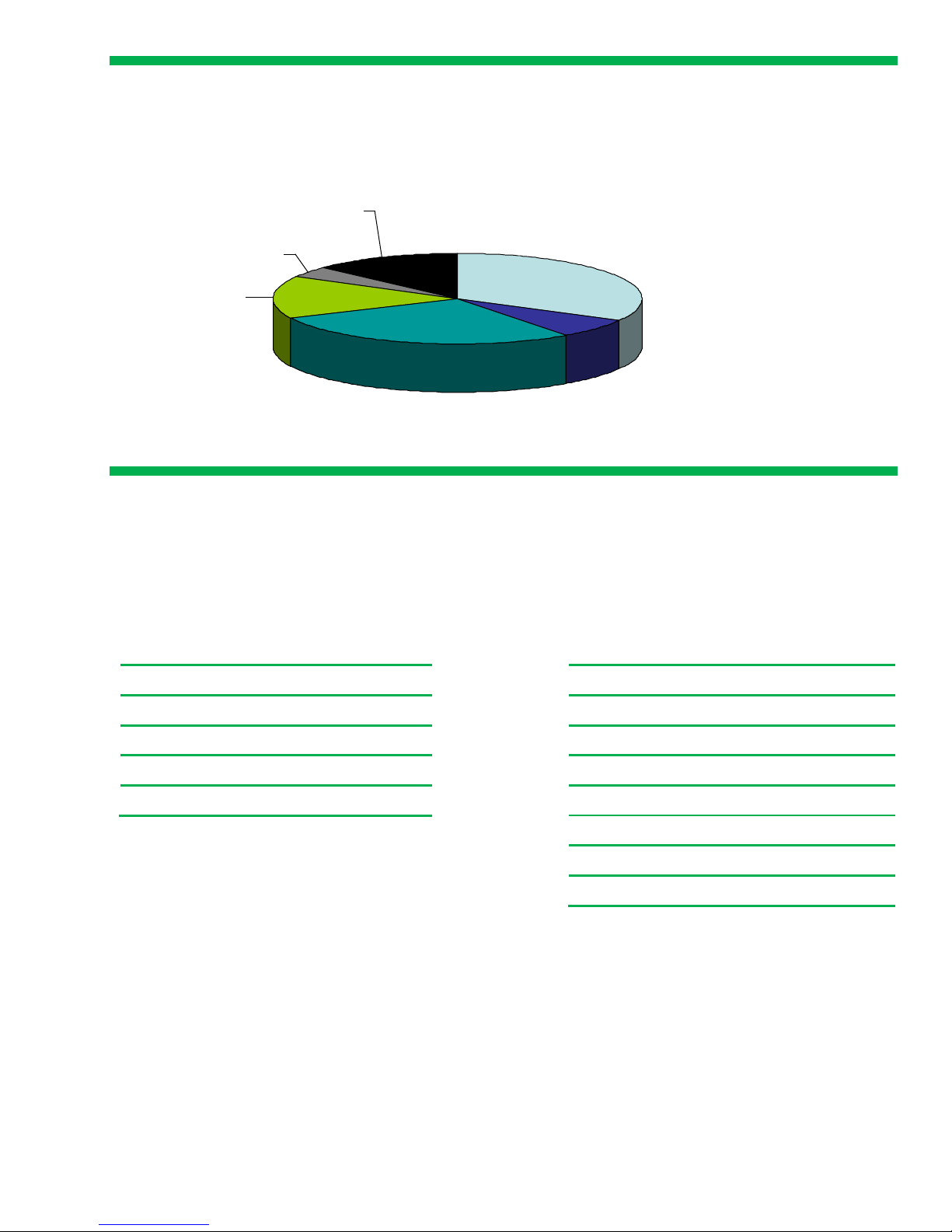
Typical Server Power Usage
Processor
33%
Fans
7%
Memory
28%
PCI Slots
15%
Hard Drives
4%
Base Load
13%
Figure 1. Power use in a typical server
Processor P-states
Processor performance states, or P-states, provide a quick and effective mechanism for adjusting processor power
consumption and performance. Both Intel
®
and AMD® processors support using P-states to decrease processor
power consumption by lowering the processor’s core frequency and voltage. Tables 1 and 2 list some of the P-states
available with different processors.
Table 1. P-states of the Intel Xeon 5160 processor
P-state Core Frequency
P0 3.0 GHz
P1 2.66 GHz
P2 2.33 GHz
P3 2.0 GHz
Table 2. P-states of the AMD Opteron 2220 processor
P- state Core Frequency
P0 2.8 GHz
P1 2.6 GHz
P2 2.4 GHz
P3 2.2 GHz
P4 2.0 GHz
P5 1.8 GHz
P6 1.0 GHz
Clock throttling
Clock throttling is another method for lowering processor power consumption. Depending on the processor model,
the system BIOS can either reprogram the processor to run at a lower frequency or modulate the processor between
running periods and stopped periods. Both methods have the same net effect of lowering the processor’s overall
power consumption below the levels available using P-states. The chart in Figure 2 illustrates the relationship
between consumed power and overall performance when using P-states and clock throttling to control server power.
Using P-states clearly provides greater power reduction for a smaller loss in performance. However, using P-states
can lower power consumption only to a certain point. Reducing consumption below that point requires the use of
clock throttling.
4
Page 5
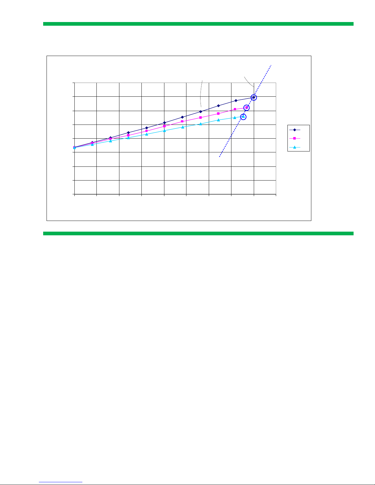
DL360 G4 Power vs. Work Done
0
50
100
150
200
250
300
350
400
0 500 1000 1500 2000 2500 3000 3500 4000 4500
Iterations
Watts
P0
P1
P2
Performance
Watts
P-state slope
Clock Throttling slope
1.00.25 0.750 0.5
Relative Performance
Figure 2. Power versus performance characteristics for a typical Intel-based ProLiant server with three P-states
How power capping functions
Maintaining power consumption below the cap
With power capping, an administrator can set a maximum power consumption level for an individual server or for
a group of servers. The ProLiant power management system constantly monitors server power use. It adjusts P-states
and/or clock throttling to limit processor power use and control overall system power consumption. As needed, the
power capping control mechanism lowers the server’s power consumption in a controlled manner to keep it below
the cap―without affecting the server workload or environment.
Server power consumption depends on many factors and can vary significantly over a given period. Some factors,
such as the number of options installed in the server, have a predictable and static effect on server power
consumption. Other factors have a dynamic effect on power consumption, for example the temperature in the data
center; the activity of the CPU, memory, disk drives, and I/O subsystems; and even the mix of instructions executed.
As long as the power consumption remains below the power cap, the power capping control mechanism takes no
action and there is no affect on server performance.
Minimum and maximum power consumption for a server
The power management system in each server determines both the minimum and maximum power consumption for
the server. It determines these two values during the server’s power-on self test (POST) by executing tests measuring
server power consumption in idle mode and under a simulated maximum load. Because they are determined
empirically, the two power values implicitly take into account the server configuration and its current physical
environment. The Insight Control and iLO interfaces display both values to provide key information that
administrators can use to set effective power caps.
The power management system in the server supplies one additional metric: maximum available power for the
server. For ProLiant ML and ProLiant DL servers, this value is the maximum power that the server power supply can
5
Page 6

produce. However, the enclosure’s power supply array powers HP BladeSystem servers. For a blade server, the
maximum available power is the amount of power that the enclosure’s Onboard Administrator reserved for that
server blade. Both iLO and Insight Control report this value: iLO reports it as Power supply maximum power for ML
and DL servers and as Initial power-on request value for BladeSystem servers.
Minimum and maximum power consumption values for a server can change slightly while the server is running.
During normal operations, iLO and the power management system continue to check both the 10-second average
and the peak power readings for the server. iLO will raise the maximum power consumption level if it measures a
peak value above the established maximum. iLO will lower the minimum power consumption if it reads an average
power value that is below the present minimum.
Differences between HP Dynamic Power Capping and HP Power
Capping
Both HP Dynamic Power Capping and HP Power Capping maintain a server’s power consumption at or below the
cap value set by an administrator. HP Dynamic Power Capping monitors power consumption and maintains a
server’s power cap much faster than HP Power Capping. Table 3 provides a quick architectural and operational
comparison of HP Dynamic Power Capping and HP Power Capping. To avoid confusion between the two, we will
refer to HP Power Capping as basic Power Capping throughout the remainder of this paper.
Table 3. Characteristics of Dynamic Power Capping and basic Power Capping
Dynamic Power
Capping
Power capping
executed from
Control of processor
power
Power monitoring cycle More than 5 times per
Time to bring server
power consumption
back under its cap
Intended application Managing power and
Power management
microcontroller
Direct hardware
connection to
processor to control Pstate/clock throttling at
the processor
hardware level
second
Less than 0.5 seconds 10 – 30 seconds
cooling provisioning
Basic Power Capping
iLO and system ROM
BIOS
Firmware control of Pstate/clock throttling
through processor
registers
Once every 5 seconds
Managing cooling
provisioning
Power provisioning and Dynamic Power Capping
Basic Power Capping does an excellent job of maintaining average server power utilization at or below a cap
value. Administrators can use it to help manage data center cooling requirements: Limiting server power
consumption fast enough can prevent excessive heat generation. However, as the information in Table 3 illustrates,
basic Power Capping cannot respond quickly enough to limit sudden increases in server power consumption that
could trip an electrical circuit breaker.
Dynamic Power Capping operates more than 25 times faster than basic Power Capping. Dynamic Power Capping
can bring a server experiencing a sudden workload increase back under its power cap in less than one-half second.
This is fast enough to prevent any surge in power demand that could cause a typical data center circuit breaker to
6
Page 7

trip. HP has tested Dynamic Power Capping to ensure that it can prevent tripping circuit breakers that have a
specified trip time of 3 seconds or longer at 50 degrees C and 150 percent overload.
Dynamic Power Capping can keep server power consumption below the power cap in real time. Therefore,
administrators can use it as an effective tool in planning and managing both electrical provisioning and cooling
requirements in the data center. An administrator can electrically provision a PDU or a rack to something less than
the full faceplate power rating of all the servers supported because Dynamic Power Capping will prevent a sudden
power demand from exceeding the power cap and tripping a circuit breaker.
Support for Power Capping in ProLiant servers
ProLiant servers with power measurement circuitry support basic Power Capping:
• ProLiant G5 servers ML350, ML370, DL360, DL365, DL380, and DL385
• All c-Class BladeSystem servers
Basic Power Capping requires the following system firmware:
• iLO 2 version 1.30 or later
• System BIOS 2007.05.01 or later
Support for Dynamic Power Capping requires a certain level of ProLiant hardware, as well upgrades to the
following system firmware:
• System BIOS 2008.11.01 or later
• iLO 2 version 1.70 or later
• Onboard Administrator firmware version 2.32 or later (for HP BladeSystem enclosures)
At introduction, support for Dynamic Power Capping is available on a limited set of ProLiant servers and a larger set
of ProLiant c-Class server blades. Many ProLiant G5 servers can support Dynamic Power Capping if they have fully
qualified BIOS and iLO firmware. Please consult the most recent
support matrix.
Group power capping for servers through Insight Control
One of the most powerful uses of power capping is monitoring and controlling the power use of an entire group of
servers. This capability is available through Insight Control. Administrators can apply a group power cap to any
group of servers that they can select within Insight Control, including Insight collections.
Insight Control displays the aggregated minimum and maximum power consumption for an entire group of servers
and their aggregated power supply rating. Each of these numbers is simply the sum of the respective values for the
individual servers in the group. Using the Insight Control interface, an administrator can apply to the server group a
power cap that is between the minimum power and the power supply rating of the entire group.
Insight Control assigns an individual power cap to each server in the group. It is a proportional allocation of the
group power cap. The total of the individual power caps equals the group cap. The individual power caps for the
servers continue until an administrator changes them through the iLO or Insight Control interface.
Figure 3 shows a group consisting of four servers. The left side of the figure shows the measured minimum and
maximum power consumption for each server. The right side of the figure shows that the aggregated maximum
power consumption for this group is 1375 watts. The aggregated minimum allowable power consumption is 725
watts. In this example, an administrator has applied a power cap of 1115 watts to the group. This group cap limits
the group power consumption to 60 percent of the wattage between the aggregated minimum and maximum. To
implement this group power cap, Insight Control applies to each server a power cap that is 60 percent of the
wattage between that server’s minimum and maximum power consumption. This results in individual power caps of
320, 170, 305, and 320 watts respectively.
7
Page 8
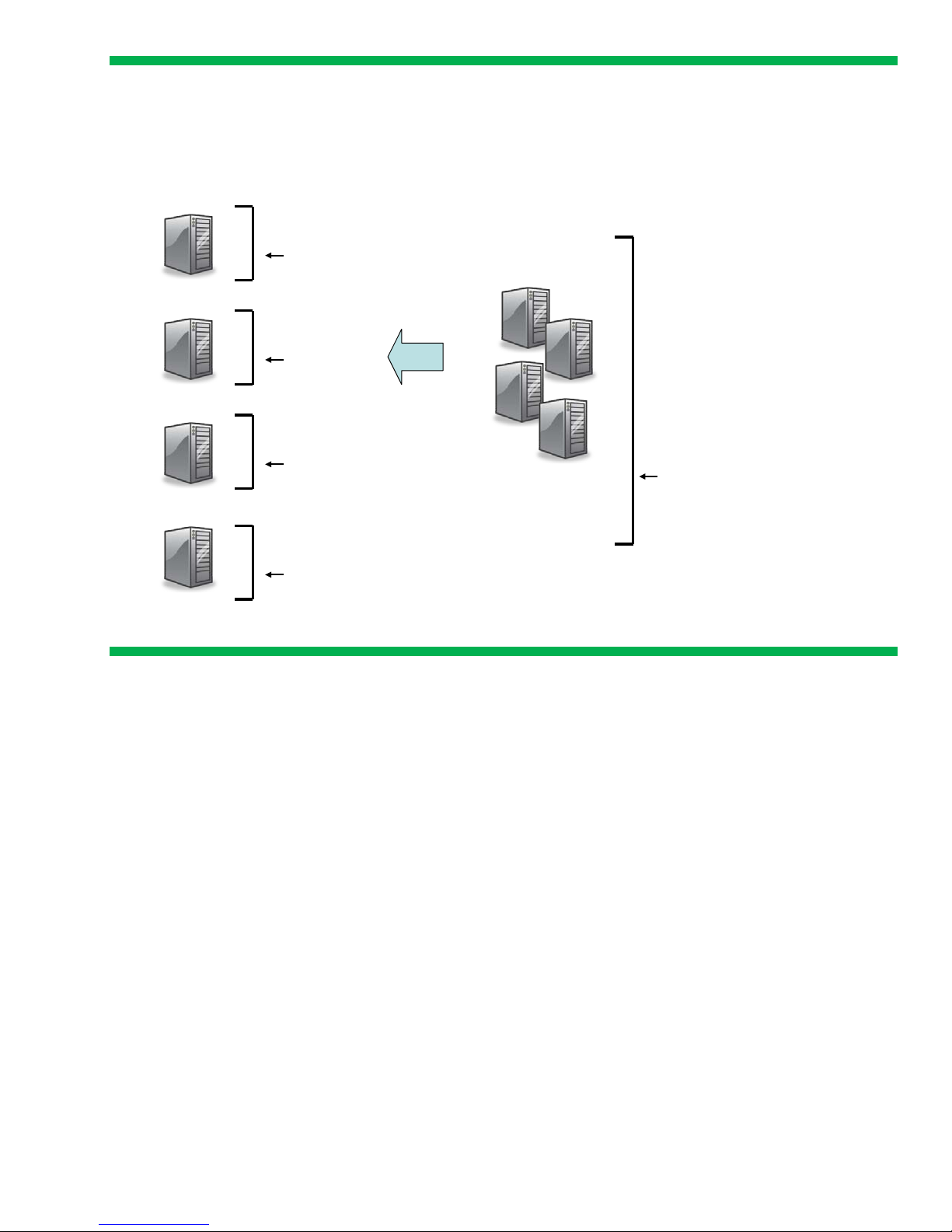
Group Power Capping
Individual Servers
400 watts (Maximum)
200 watts (Minimum)
Servers as a Group
320 watts (Apportioned Cap)
200
125
170
375
200
400
200
305
320
1375 watts
(Group maximum)
725 watts
(Group minimum)
1115 watts
(User set group power cap)
1000 watts (Power supply maximum)
1000
1000
500
3500 watts
(Group power supply
maximum)
Figure 3. Apportioning a group power cap to individual servers in the group
Group power capping apportionment works exactly the same way on ProLiant ML and DL servers with either
Dynamic Power Capping or basic Power Capping. For server blades, there is a more advanced feature called
Enclosure Dynamic Power Capping.
Enclosure Dynamic Power Capping
Enclosure Dynamic Power Capping is a special implementation of Dynamic Power Capping for HP BladeSystem
enclosures. In one sense, it is a higher level of power management functionality, since an administrator sets and
maintains a power cap at the enclosure level rather than directly at the server or blade level. In another sense, it is a
more powerful implementation of group power capping for an enclosure: Setting a power cap for the enclosure
indirectly creates power caps for the server blades within it. The Onboard Administrator (OA) then actively
manages these power caps and reallocates power as workloads change over time.
Elements of an enclosure power cap
With Enclosure Dynamic Power Capping, an administrator sets a power cap for an entire BladeSystem enclosure,
not simply for the server blades in the enclosure. Total power consumption for an enclosure is the sum of the power
used by all of these components:
• Server blades
• I/O peripherals for the enclosure (interconnects, etc.)
• Cooling fans for the enclosure
• Onboard Administrator(s)
8
Page 9

An administrator can set the enclosure power cap to any value between the lowest total power consumption and the
Blade Power
Budget
Power used
by unmanaged
elements
Enclosure
Dynamic
Power Cap
Power Cap
Lower Bound
Enclosure
Dynamic
Power Cap
Time A Time B
Enclosure Dynamic Power Capping
Power Budgeting
Power Cap
Lower Bound
maximum available power for the enclosure. Adding these values yields the lowest reasonable power cap
maintainable for the enclosure under all operating conditions:
• Total power that the server blades would use in their lowest power-capped state (typically about halfway between
server idle and server maximum power)
• Maximum power that fans in the enclosure could draw
• Power-on power requests from the other elements in the enclosure
The maximum available power for the enclosure is the total power available from the enclosure power supplies.
Operation of Enclosure Dynamic Power Capping
Once an administrator sets an enclosure power cap, the enclosure OA monitors and maintains the cap. The OA
cannot control the power consumption of unmanaged elements in the enclosure (fans, switches, and others). The OA
maintains the overall enclosure cap by monitoring and managing the power consumption of the server blades. To
accomplish this, the OA collects the overall enclosure power use and the total power used by the managed server
blades. From this data, the OA constructs a blade power budget representing the amount of power that the blades
can consume while keeping the overall enclosure power consumption below the enclosure cap. As a final step, OA
software actively adjusts the power caps of the individual servers so that the total matches the enclosure power
budget. This process repeats every 20 seconds to maintain the enclosure power cap. As Figure 4 illustrates, the OA
increases the blade power budget and the power caps for the individual server blades if power consumption of the
unmanaged elements in the enclosure decreases.
Figure 4. Power budgeting in Enclosure Dynamic Power Capping
9
Page 10

Active power reallocation
One of the more important features of Enclosure Dynamic Power Capping is the active reallocation of power
amongst the server blades over time. After each monitoring cycle, Enclosure Dynamic Power Capping actively
reapportions the individual power caps of the server blades based on their individual workloads. With the blade
power budget as its limit, the OA software uses a sophisticated, multi-tiered algorithm to increase the power caps of
individual servers that are busier and using more power. It decreases the caps for server blades using less power
from cycle to cycle. Thus, the OA optimizes the power use among the server blades in the enclosure while keeping
overall power consumption below the enclosure power cap. To maintain control of the server power caps, Enclosure
Dynamic Power Capping disables external changes to the server caps using either iLO or Insight Control.
In most cases, the OA can quickly raise a low power cap for an idle server blade that receives new work. In such
cases, the power-sharing algorithm has little impact on performance. However, if there are too many busy server
blades for the available power, the OA will attempt to share the available power fairly among all busy server
blades.
Enclosure Dynamic Power Capping in mixed blade environments
Enclosure Dynamic Power Capping operates with all server blades that support basic Power Capping or the faster
Dynamic Power Capping. It also provides circuit breaker protection using either of these types of server blades. To
accomplish this, Enclosure Dynamic Power Capping relies on the extra circuit capacity of enclosures configured with
N+N redundant power. Basic Power Capping cannot bring server blades under their caps within the 3 seconds
required for normal circuit breaker protection. However, the redundant side of the enclosure power can absorb the
transient overage until overall power consumption is again under the enclosure cap. If N+N power redundancy
fails, then a hardware-based failsafe mechanism overrides the Enclosure Dynamic Power Capping and immediately
lowers all server blade processors to a predetermined power state that prevents a circuit breaker overload. This
hardware override continues until power redundancy is restored.
Opting out servers
An administrator may want to leave some server blades uncapped, even though that may result in lower power
caps for the other server blades in the enclosure. Typically, uncapped servers run mission critical or consistently high
workload applications that require unconstrained power consumption. This allows them to maintain high throughput
and low latency response times. Enclosure Dynamic Power Capping allows an administrator to “opt out” of power
management for up to one quarter of the server blades in an enclosure, making them unmanaged elements. Looking
again at Figure 4, the OA measures and tracks the power these servers consume, but it is part of the power used by
the unmanaged elements pool. The enclosure power cap remains the same, so the blade power budget for the
remaining managed server blades becomes smaller.
Setting power caps for servers
Administrators can use iLO or Insight Control to set individual power caps for servers. Using Insight Control, you can
also set power caps for groups of ProLiant ML and DL servers and for groups of enclosures. For individual
enclosures, you can set power caps using the OA or Insight Control. You set power caps in exactly the same way
on servers supporting Dynamic Power Capping or basic Power Capping. Servers supporting Dynamic Power
Capping simply enforce the cap using the faster power management architecture.
10
Page 11

Setting a power cap for a single server
Administrators can set a power cap for an individual server or server blade through iLO or through Insight Control.
In the iLO 2 browser-based interface (Figure 5),
tab in the Settings subsection. The iLO 2 Power Management Settings screen indicates whether the server supports
Dynamic Power Capping.
Figure 5. Setting a power cap for an HP BladeSystem server using iLO 2
Power Capping Settings is located beneath the Power Management
11
Page 12

In Insight Control, Power Capping is located beneath the HP Power Management Actions section of the interface, as
shown in Figure 6.
Figure 6. Setting a power cap for an HP BladeSystem server using Insight Control
12
Page 13

Setting a power cap for a group of servers
Insight Control is the sole tool for setting power caps for groups of ProLiant ML and DL servers. Using the Insight
Control interface (Figure 7), an administrator can apply a group power cap that is between the minimum power
and the power supply rating of the entire group.
Figure 7. Setting a group power cap in Insight Control
Setting a BladeSystem enclosure power cap
You can use either the OA or Insight Control to set the power cap for a BladeSystem enclosure to any value
between the power cap lower bound and the maximum available power for the enclosure. Figure 8 shows the
Power Management screen from HP Onboard Administrator. This screen is where you set the Enclosure Dynamic
Power Cap.
13
Page 14

Figure 8. Setting an Enclosure Dynamic Power Cap in HP Onboard Administrator 2.60
Setting a power cap for a group of enclosures
An administrator can use Insight Control to apply enclosure dynamic power caps to a group of enclosures at the
same time. Figure 9 shows five BladeSystem c-Class Enclosures configured as a group in Insight Control. The
maximum available power for the group is 31,784 watts. The lower bound of the power cap is 15499 watts. It is
higher than the maximum power measurement because it represents the lowest reasonable power cap for the group
that is sustainable under all operating conditions. Applying a power cap value of 25,000 watts to the group
causes Insight Control and the OAs to create and apply a separate Enclosure Dynamic Power Cap to each of the
five enclosures, using the same
to ML and DL servers. The OA within each enclosure will use this power cap to determine a blade power budget for
proportional allocation method described earlier for applying a group power cap
14
Page 15

the enclosure and to create power caps for the individual server blades. It will then monitor and adjust the
individual server blade power caps based on their power demands.
Figure 9. Setting a power cap for a group of enclosures in Insight Control
Using power capping in data center provisioning
Power capping is a tool to help IT organizations manage infrastructure size and costs in the data center. Setting a
power cap for a server or group of servers assures a data center manager that unexpected changes in workload or
environment will not cause servers to consume more than the specified amount of power.
Appropriate use of basic Power Capping in the data center lets administrators provision the cooling infrastructure at
an effective level. Effective provisioning meets cooling requirements associated with server power consumption at a
realistic application load, when having all servers running at full power is unrealistic. Alternatively, using basic
Power Capping to limit average server power consumption will allow operating more servers safely within a preexisting cooling infrastructure.
Dynamic Power Capping takes this one step further. Its ability to control server power consumption in real time
allows administrators to use power capping for planning and managing both their electrical provisioning and their
cooling infrastructure.
Choosing effective power caps
Setting an effective power cap involves determining the lowest value for the power cap that will still meet the power
requirements for a server or group of servers running their application workload. An effective power cap should
have no affect on server application performance but would reduce the required cooling and electrical provisioning
for the servers.
Administrators can use the HP Power Calculator Utility to estimate the maximum input power for a given server
configuration. This information provides a starting point for considering power caps. Once you have deployed an
application in a laboratory or in production, reporting features in Insight Control and iLO provide historical power
consumption data. You can use that data to refine the power cap selection to achieve specific power savings or
capacity planning targets.
Figure 10 shows the output from the HP Power Calculator utility for a ProLiant DL380 G5 server configured with two
Quad-Core Intel Xeon X5460 3.16-GHz processors, one 72-GB disk drive, and 8 GB of system memory. The results
15
Page 16

indicate that the Total System Input power requirement for this server configuration is 423 watts. This is the
predicted maximum amount of power that this server configuration would use under environmental and load
conditions. It is one of the numbers that an administrator could use when calculating the maximum power and
cooling requirements to support this system in the data center. For a rack containing a group of eight of these
servers, the total requirements would be 3384 watts.
Figure 10. HP Power Calculator results for a configured ProLiant DL380 G5 server
16
Page 17

Continuing with this example, Figure 11 shows the Insight Control Group Power Consumption graph for the group
of eight servers running a typical variable load application. Insight Control generates this graph using data
collected from each server’s power management system. The power management system measures power
consumption twice per second and records both the peak and average power consumption. For peak power
consumption, each point in the graph represents the highest half-second power measurement recorded during a
given 5-minute period. The average power consumption denotes the arithmetic mean of all half-second power
measurements recorded over the same timeframe.
Figure 11. Group Power Consumption graph for a group of eight ProLiant DL380 G5 servers
The peak power consumption for the server group running this particular workload is about 3116 watts. The
average power consumption is about 1900 watts. Knowing the history of peak and average power consumption for
the group provides a good starting point for deciding how to set effective power caps that meet different power
management objectives in the data center.
Power capping to peak power consumption
As the power consumption graph in Figure 11 shows, peak power consumption for the eight-server group running
this workload is consistently about 3116 watts. Setting a power cap at this level would have no affect on overall
server performance. A 3116-watt power cap will ensure that the server group’s power consumption will not
normally exceed 3116 watts for any significant period. For basic Power Capping, an administrator could safely
define cooling requirements for the server group against 3116 watts of power consumed rather than against the
larger maximum power number of 3384 watts that the HP Power Calculator Utility shows for this configuration. A
guardband (described later in this paper) is not necessary in this example for two reasons. First, eight servers are
enough for the average meter error to be small. Second, in this example the caps are set to the measured peak,
17
Page 18

which is high in the dynamic range of the servers. So the effects of configuration and environmental changes are
Description
Power
Description
Power
ignored. Table 4 shows a summary of the power consumption and capacity savings for the server group.
Table 4. Power consumption for eight DL380 G5 servers when capping to peak power consumption using basic Power Capping
Maximum possible power consumption for 8 DL380 G5 servers
(based on HP Power Calculator)
Maximum power consumption when capping to peak 3116 watts
Savings in power capacity 268 watts
Additional servers that can be provisioned within the same cooling infrastructure 0.7
3384 watts
If all eight servers supported Dynamic Power Capping, administrators could use the 3116-watt power cap to
manage electrical provisioning rather than provisioning to the faceplate value of the power supply. Table 5
illustrates how many more servers the same circuit could power under the 3116-watt power cap. Derating the
faceplate value by 20 percent requires 7760 watts. This example reserves a 10 percent guardband for other factors
(see “Providing a guardband for a power capping group”). With Dynamic Power Capping applied, the same
circuit can support over 10 more servers, if all 10 have the same power cap as the first eight servers.
Table 5. Power provisioning for eight DL380 G5 servers when capping to peak power consumption using Dynamic Power
Capping
Traditional input power provisioning for 8 DL380 G5 servers
(1217 input VA at 208 volts de-rated by 20 percent)
Maximum power consumption when capping to peak 3116 watts
Guardband 312 watts
Savings in power capacity 4332 watts
Additional servers that can be provisioned within same 7760 watts using Dynamic Power
Capping when capping to peak
7760 watts
(970 x 8)
10.1
It is important to understand this: Capping to peak based on the power consumption graph for a server group is
actually capping to the peak of the total power consumptions of servers in the group. It assumes that all the servers
in the group consume the same amount of power. This would not be true under these conditions:
• If the servers were configured differently
• If workloads on individual servers peaked at different times
• If workloads varied significantly from server to server
If all servers in the group did not consume the same amount of power, the cap in this example would have an
adverse affect on server performance, especially if they support Dynamic Power Capping. If the servers in a group
18
Page 19

are not all the same, HP recommends using Insight Control to review the peak power consumption of each server to
Description
Power
ensure that the selected Dynamic Power Cap will not significantly limit its actual peak power consumption.
Power capping to average power consumption
An administrator can further increase provisioning capacity by capping the example group shown in Figure 11 at
the average power consumption: 1900 watts. Capping to average power consumption should not significantly
affect overall average computing throughput of servers running fairly uniform workloads. However, it may increase
latency during workload peaks or marginally affect the overall server performance in some applications.
The case shown in Table 6 reserves a 10 percent guardband for other factors (see “Providing a guardband for a
power capping group”). Even so, capping to average with basic Power Capping allows provisioning of over
60 percent more servers within a given cooling infrastructure.
Table 6. Power consumption for eight DL380 G5 servers when capping to average power consumption using basic Power
Capping
Maximum power consumption for 8 ProLiant DL580 G5 servers
(based on HP Power Calculator)
Maximum power consumption when capping to average 1900 watts
Guardband 190 watts
Savings in power capacity 1294 watts
Additional servers that can be provisioned within the same cooling infrastructure 5
3384 watts
Dynamic Power Capping will more significantly affect any workload transients exceeding the cap. Therefore, HP
recommends capping a server group supporting Dynamic Power Capping at the average power consumption only
in applications where peak transient performance is not a concern. Higher guardbands for the group might be
appropriate as well.
Using Enclosure Dynamic Power Capping in power provisioning
Dynamic Power Capping can control server power consumption quickly enough to prevent transient server power
demands that may trip circuit breakers in the data center. Using Enclosure Dynamic Power Capping, an
administrator can essentially cap the electrical provisioning for an enclosure by setting an enclosure power cap.
For example, consider an HP BladeSystem c7000 enclosure fully configured with 16 server blades. Provisioning the
power to the total of the HP 2250W power supplies’ specification requires delivering 7836 watts to the enclosure.
You would typically use a single 30-amp 3-phase 208-volt circuit, which has a total capacity of 8640 watts.
However, if the enclosure’s peak power consumption over time is less than 4000 watts, you can provision and
operate two full enclosures from the same circuit with no performance loss, if you cap both enclosures at 4000-watts
(Figure 12).
19
Page 20

0 Watts
4000 Watts
(Measured Peak)
7836 Watts
(PSU Specification)
P ower P rovisioned to P SU
•
2612 x 3 = 7836 wat ts
•
S ingle 3Ø L ine = 8640
•
16 B lades per 8K W
Power Provisioned to Cap at
Measured Peak
• ≈4KW enclosure
• 32 Blades per 8KW
Power Provisioning with
Enclosure Dynamic Power Capping
Figure 12. Provisioning with Enclosure Dynamic Power Capping
Note that the group control algorithms used for Enclosure Dynamic Power Capping compensate for variables such
as hot-add disk drives and changing fan power, so no additional guardband is required.
The white paper “
Capping and Enclosure Dynamic Power Capping to manage data center power provisioning.
Dynamic Power Capping TCO and Best Practices” provides more detail on using Dynamic Power
Additional uses for power capping
You can use both basic Power Capping and Dynamic Power Capping in other ways in the data center, including
emergency management and automatic power control during peak demand periods.
Power capping for emergency management
You can use power capping to manage server power consumption effectively when unforeseen circumstances arise.
For example, if a cooling system fails in part of a data center, you can manually lower the power cap on a group of
servers using Insight Control and power capping. This will quickly lower server power consumption and heat
generation in the affected area until you can restore cooling. Under these circumstances, it may be appropriate to
set power caps significantly lower, even though they may affect performance. Using HP SIM, you can define and
store groups of servers as collections. This allows you to apply power caps to these groups quickly in an
emergency.
Similarly, if all or part of a data center loses primary AC power, you can immediately apply a group power cap to
lower power consumption for server groups. This reduces the power drain on data center Uninterruptible Power
Supplies (UPSs), which increases the maximum window of time that the data center can remain operational after a
power failure but before the on-site generators restore power and cooling.
20
Page 21

Time-of-day power capping
Insight Control has task-scheduling capabilities. Administrators can create time-of-day power capping for a server or
group of servers that lowers and raises power levels in a pre-determined pattern, typically on a daily cycle.
Lowering the power cap on a group of servers when electricity rates are highest will lower operating costs. It
decreases the average power use by the servers and, indirectly, decreases required cooling.
To construct a time-of-day power capping scenario, you must create scheduled tasks in Insight Control. In the SIM
interface, you access this scheduling capability using the Configure, Power Management, Power Usage Controls
menu.
Task scheduling consists of several steps, including defining the new power cap (Figure 13) and creating the
schedule for applying the power cap (Figure 14).
Figure 13. Setting a power cap as part of a scheduled task
Figure 14. Defining the scheduled Insight Control task in Systems Insight Manager
Constructing a time-of-day power capping model actually requires creating at least two separate scheduled tasks in
Insight Control. The first step is to create a scheduled task to apply a power cap at a given time of day. Figures 13
and 14 show a power cap applied at 2:00 PM every day. Completing the time-of-day power capping requires
creating a second task to remove or raise the power cap.
21
Page 22

Subtleties of power capping
Avoiding power capping conflicts within groups
Insight Control is a powerful tool for setting and managing power caps across defined groups of servers, including
SIM collections. It is important to remember, however, that except for Enclosure Dynamic Power Capping, power
caps are ultimately set at the individual server level. Insight Control apportions a group power cap as individual
power caps to all of the servers in the group.
Power capping is also completely non-hierarchical. A power cap set using Insight Control has no precedence over a
power cap set using the iLO interface. Each server conforms to the last power cap that it received, regardless of the
method used to set it.
For example, consider this situation: A server is a member of two distinct SIM collections. An administrator applies a
group power cap to each of these collections. The individual power caps of servers in both collections will be the
last cap applied to either collection. Later an administrator uses the iLO interface to set a power cap on an
individual server within one of the collections. For that server, the new cap will replace the previous power cap that
had been set through Insight Control.
A similar situation can occur when administrators use Insight Control to set enclosure dynamic power caps for
groups of enclosures. Setting a new cap on a single enclosure through its OA can overwrite a group power cap
previously apportioned to the individual enclosures.
This potential overlap in setting power caps is important to consider when planning and implementing an overall
power capping/capacity management strategy. Choosing a single consistent method for setting power caps is the
best way to avoid conflicts. For example, a system administrator could define a set of non-overlapping SIM
collections used specifically for power and cooling management.
Powering up groups of servers when using Dynamic Power Capping
HP Dynamic Power Capping is a powerful tool for controlling the steady-state power consumption of servers in real
time. However, it does not control the power consumption of servers at start-up when their maximum power
consumption is measured. If a group of servers on the same PDU power-up simultaneously, there will be a window
during start-up before Dynamic Power Capping is active. During that window, the servers will draw close to their
maximum power at roughly the same time. If this peak is too large, it may cause problems. Therefore, it is important
to manually power on these server groups in a staggered manner. Administrators using the iLO interface or the
enclosure OA for BladeSystem servers can stagger auto power-ups by enabling the servers’ Power On Delay and
setting it to “Random up to 120 seconds.”
Setting low or unattainable power caps on servers
In theory, administrators can set a power cap to any value above the minimum power consumption for a given
server or a group of servers. However, setting power cap values close to the minimum power consumption is not
good practice. Maintaining a power cap at or near this level prevents the server from accomplishing meaningful
work. Also, a server’s minimum power consumption level may rise over time for a number of causes, including
increased fan activity as data center temperatures rise or hot-adding disk drives to the server. A power cap
becomes unachievable if the minimum power consumption of the server rises above it. In this situation, the capping
subsystem will cap the power consumption as low as it can and report that the power cap is unachievable.
Best practice is to re-evaluate the cap value after adding any hardware to the server, and to use power caps that
are at least halfway between the minimum and maximum power consumption for a server or server group. Both the
iLO and Insight Control interfaces provide a warning when a power cap value is lower than this.
Enclosure Dynamic Power Capping has resolved much of this issue. It disallows enclosure power caps that are too
close to the aggregate minimum power for the enclosure and its server blades. However, setting a very low cap
value for the enclosure can prevent blades in the enclosure from accomplishing meaningful work.
22
Page 23

Peak power reporting and Dynamic Power Capping
Both iLO and Insight Control report the power metrics for ProLiant servers, including peak power consumption. The
power monitoring system for servers records peak power consumption as the largest half-second power
measurement in a 5-minute period. It can take up to one-half second to bring a server’s power consumption back
below the cap. As a result, it is possible to see reported peak power numbers that are several watts above a
server’s power cap value. Dynamic Power Capping still provides circuit protection, since it will always bring server
power consumption below the cap long before a circuit breaker can trip.
Using HP Power Regulator in conjunction with power capping
Power capping and HP Power Regulator use the same underlying power management system to manage and
control server power consumption. However, HP designed these two power management features to accomplish
different goals.
Power capping provides strict control of a server’s maximum power consumption. It can limit a server’s maximum
power consumption over a wider range of power than Power Regulator can, without regard for the affect on system
performance. Power capping can use both processor P-states and clock throttling to limit system power consumption.
Power Regulator focuses on optimizing power use in a server (or group of servers) without affecting server
performance. In its recommended configuration, Power Regulator dynamically selects the most power-efficient
processor P-state that matches the present workload of the server. By doing this, Power Regulator lowers power
consumption without affecting system performance or throughput. In this sense, Power Regulator is primarily an
efficiency tool.
Administrators can use power capping and HP Power Regulator on an individual server or server group at the same
time without creating a conflict. Power Regulator manages server power use as long as a server’s power
consumption remains below the power cap setting. Power capping will override Power Regulator only if power
consumption exceeds the established power cap.
Power capping and CPU utilization
Both power capping and Power Regulator involve manipulating the system processor at a very basic level. As a
result, power capping can affect the processor utilization that monitoring tools report at the operating system level. If
a server with a relatively constant workload has a power cap low enough to engage the power control mechanisms,
OS monitoring utilities will generally report a greater CPU utilization number than they would if the cap were not in
place.
Power capping and option cards
The server’s capping circuit indirectly controls option cards installed in PCI Express slots. That is, as the capping
circuit decreases to keep the server power below the cap, the processor is less able to issue commands to the card.
Option cards that consume much more power during normal operation than during the maximum-power test at
POST complicate identifying the server’s maximum and minimum power consumption and the minimum capping
threshold. As best practice, allow an application that includes such option cards to run several minutes before
choosing a cap value so iLO can measure the true application power.
Providing a guardband for a power capping group
The sophisticated algorithms used by Enclosure Dynamic Power Capping automatically manage all the conditions
that can affect the total enclosure power consumption. However, they do not automatically manage individual
servers singly through iLO or as groups through Insight Control. You must manually manage other factors that are
beyond the control of the individual server power capping subsystem. After considering all of these factors, you
should set aside some percentage of the available power as a reserve or guardband. The total amount of
guardband that is appropriate for any installation will depend on the servers and the size and behavior of the
environment of that installation.
23
Page 24

Administrators should consider the following factors for determining the amount of power to reserve as a
guardband:
• The guardband should allow any individual server in the group to power up at full power while constraining
other servers on the same circuit to their cap value. The preceding “Powering up groups of servers when using
Dynamic Power Capping” section illustrates this.
• If only a few servers share a circuit, administrators should apply additional guardband equal to the worst-case
tolerance of the server power meters. However, meter errors can be both positive and negative, so guardband
for meter tolerance, as a percentage of the cap, can approach zero as the number of servers increases.
• Hardware and environmental changes can increase server power consumption and cause a power cap to affect
performance. In the extreme, the power cap can become unachievable, as described in “Setting low or
unattainable power caps on servers.” Administrators expecting to make significant hardware or environmental
changes for one or more servers should increase guardband to the group total to allow for the changes.
However, best practice is to re-evaluate the server caps after adding hardware and to select caps that are at
least halfway between the minimum and maximum power consumption for a server or server group. When you
follow best practices, additional guardband at the group level is generally not necessary.
Tables 5 and 6 show examples of applying a guardband to a group of servers.
Summary
HP Power Capping and HP Dynamic Power Capping are important power management features of HP ProLiant
servers. System administrators can use power capping to set limits on power consumption for a single server or
groups of servers that do not affect server performance. Administrators can provision data center power and cooling
resources to appropriate levels rather than to unrealistic maximum requirements. Enclosure Dynamic Power Capping
is the newest and most sophisticated implementation of power capping. It can actively reallocate an enclosure’s
power cap across individual server blades based on their workload requirements.
24
Page 25

For more information
Source Hyperlink
HP Power Management
HP Insight Control
HP Integrated Lights-Out
HP SIM page on hp.com
Dynamic Power Capping TCO
and Best Practices white paper
Dynamic Power Capping
support matrix
HP Power Calculators page
HP ProLiant Energy Efficient
Solutions
Power Regulator for ProLiant
servers technology brief
Power Regulator
http://www.hp.com/go/powercapping
http://www.hp.com/go/insightcontrol
http://www.hp.com/go/ilo
http://www.hp.com/go/hpsim
http://h71028.www7.hp.com/ERC/downloads/4AA2-3107ENW.pdf
http://h18004.www1.hp.com/products/servers/management/dynamic-powercapping/support.html
http://h30099.www3.hp.com/configurator/powercalcs.asp
www.hp.com/go/proliant-energy-efficient
http://h20000.www2.hp.com/bc/docs/support/SupportManual/c00300430/c00300
430.pdf
http://h18013.www1.hp.com/products/servers/management/ilo/power-regulator.html
Call to action
Send comments about this paper to TechCom@HP.com
© Copyright 2008, 2009, 2010 Hewlett-Packard Development Company, L.P. The information
contained herein is subject to change without notice. The only warranties for HP products and
services are set forth in the express warranty statements accompanying such products and services.
Nothing herein should be construed as constituting an additional warranty. HP shall not be liable for
technical or editorial errors or omissions contained herein.
AMD is a trademark of Advanced Micro Devices, Inc.
Intel is a trademark of Intel Corporation or its subsidiaries in the United States and other countries
and is used under license.
TC110107TB, January 2011
25
 Loading...