

Page 1

HP Integrity cx2600 Operations and
Maintenance Guide
HP Part Number: AB216-90006
Published: December 2010
Edition: 2
Page 2

© Copyright 2006, 2010 Hewlett-Packard Development Company, L.P
Legal Notices
The informationcontained hereinis subjectto changewithout notice.The onlywarranties for HP products and services are set forth in the express
warranty statements accompanying such products and services. Nothing herein should be construed as constituting an additional warranty. HP
shall not be liable for technical or editorial errors or omissions contained herein.
Printed in U.S.A.
Intel, Pentium, Intel Inside, Itanium, and the Intel Inside logo are trademarks or registered trademarks of Intel Corporation or its subsidiaries in
the United States and other countries.
Warranty
To obtain a copy of the warranty for this product, see the warranty information website:
BCS Global Limited Warranty and Technical Support
Page 3

Table of Contents
About This Document.........................................................................................................8
Typographic Conventions......................................................................................................................8
Related Documents.................................................................................................................................8
HP Encourages Your Comments............................................................................................................8
1 Controls, Ports, and Indicators......................................................................................9
Introduction............................................................................................................................................9
Front Panel.........................................................................................................................................9
Switch/Button and LED Definitions............................................................................................9
Additional Controls and Indicators................................................................................................10
Hot-Plug Disk Drive LEDs.........................................................................................................10
DVD/DVD-R/DVD-RW Drives..................................................................................................11
Rear Panel........................................................................................................................................11
10/100 System Management LAN LEDs....................................................................................12
Locator LEDs and Button...........................................................................................................12
MP Reset and TOC Buttons........................................................................................................12
Power Supply Status LEDs.........................................................................................................13
Gigabit LAN LEDs.....................................................................................................................13
Management Processor LAN LEDs...........................................................................................14
System Board LEDs....................................................................................................................14
Management Processor Board LEDs..........................................................................................15
2 External Connectors.....................................................................................................17
Connector Pinouts.................................................................................................................................17
Universal Serial Bus (USB) Ports.....................................................................................................17
Serial Ports.......................................................................................................................................18
System Management LAN Port.......................................................................................................18
Management Processor VGA Port...................................................................................................19
Gigabit Ethernet (LAN) and MP LAN Port.....................................................................................19
SCSI Port, Ultra 3, 68-Pin.................................................................................................................20
3 Installing Additional Components..............................................................................22
Safety Information................................................................................................................................22
Service Tools Required..........................................................................................................................22
Accessing a Rack-Mounted Server.......................................................................................................22
Installing Components When the Server Is in a Rack.....................................................................22
Removing the Server From a Rack..................................................................................................23
Install the Server into a Rack...........................................................................................................24
Installing Disk Drives...........................................................................................................................24
Removing Hot-Plug Disk Drives.....................................................................................................24
Installing Hot-Plug Disk Drives......................................................................................................25
Installing Hot-Swap Power Supply Units.............................................................................................26
Removing and Replacing a Hot-Swap Power Supply.....................................................................26
Installing the Front Grill and Top Cover..............................................................................................28
Removing the Front Grill.................................................................................................................28
Installing the Front Grill..................................................................................................................28
Removing the Top Cover.................................................................................................................29
Installing the Top Cover..................................................................................................................30
Installing Hot-Swap Chassis Fan Units................................................................................................30
Removing and Installing a Front Panel Hot-Swap Fan...................................................................31
Removing and Installing a Rear Panel Hot-Swappable Fan...........................................................33
PCI Card Installation............................................................................................................................34
Removing the PCI Card Cage Assembly.........................................................................................34
Table of Contents 3
Page 4

Removing a PCI Card......................................................................................................................35
Installing a PCI Card.......................................................................................................................36
Installing the PCI Card Cage Assembly..........................................................................................36
Installing Processors.............................................................................................................................37
Removing a Processor.....................................................................................................................38
Installing a Processor.......................................................................................................................44
Installing Memory.................................................................................................................................49
Supported DIMM Sizes...................................................................................................................49
Removing DIMMs...........................................................................................................................49
Installing DIMMs.............................................................................................................................50
4 Troubleshooting............................................................................................................53
Introduction..........................................................................................................................................53
Troubleshooting Methodology.............................................................................................................53
Troubleshooting Using the Front Panel Power Button.........................................................................53
Server Does Not Power On...................................................................................................................54
EFI Menu is Not Available....................................................................................................................54
Operating System Does Not Boot.........................................................................................................54
Operating System Boots with Problems...............................................................................................55
Intermittent Server Problems................................................................................................................55
DVD Problems......................................................................................................................................55
Hard Drive Problems............................................................................................................................55
Console Problems.................................................................................................................................55
Troubleshooting Using Beep Codes (System e-buzzer)........................................................................55
Troubleshooting Using LED Indicators................................................................................................56
Front Panel LEDs.............................................................................................................................56
Rear Panel LEDs..............................................................................................................................60
Error Messages......................................................................................................................................62
EFI Error and Warning Messages....................................................................................................62
Event Logs for Troubleshooting Diagnostics..................................................................................64
Accessing the Logs Through the MP.........................................................................................64
SEL and FPL Log Entries............................................................................................................65
Accessing the Logs With BMC CLI Commands........................................................................65
Accessing the Logs with MP Commands..................................................................................66
Disk and I/O Path Logging.........................................................................................................66
Troubleshooting Using Offline Support Tools......................................................................................67
Offline Diagnostic Environment (ODE)..........................................................................................67
E-Diag Tools.....................................................................................................................................67
Other Event Logs and General Diagnostic Tools............................................................................68
Building Up the System...................................................................................................................68
5 Utilities...........................................................................................................................73
Extensible Firmware Interface Boot Manager......................................................................................73
EFI Commands................................................................................................................................74
EFI/POSSE Commands.........................................................................................................................76
help..................................................................................................................................................76
Syntax.........................................................................................................................................76
Parameters..................................................................................................................................76
Operation....................................................................................................................................76
baud.................................................................................................................................................80
Syntax.........................................................................................................................................80
Parameters..................................................................................................................................80
Operation....................................................................................................................................80
boottest............................................................................................................................................81
Syntax.........................................................................................................................................81
Parameters..................................................................................................................................81
4 Table of Contents
Page 5

cpuconfig.........................................................................................................................................82
Syntax.........................................................................................................................................82
Parameters..................................................................................................................................82
Operation....................................................................................................................................82
default..............................................................................................................................................83
Syntax.........................................................................................................................................83
Parameters..................................................................................................................................83
Operation....................................................................................................................................83
errdump...........................................................................................................................................83
Syntax.........................................................................................................................................83
Parameters..................................................................................................................................83
Operation....................................................................................................................................83
info...................................................................................................................................................83
Syntax.........................................................................................................................................83
Parameters..................................................................................................................................84
lanaddress........................................................................................................................................90
Syntax:........................................................................................................................................90
Parameters..................................................................................................................................90
monarch...........................................................................................................................................91
Syntax.........................................................................................................................................91
Parameters..................................................................................................................................91
Operation....................................................................................................................................91
pdt....................................................................................................................................................91
Syntax.........................................................................................................................................91
Parameters..................................................................................................................................91
Operation....................................................................................................................................92
sysmode...........................................................................................................................................92
Syntax.........................................................................................................................................92
Parameters..................................................................................................................................92
Operation....................................................................................................................................92
Specifying SCSI Parameters..................................................................................................................93
Using the SCSI Setup Utility............................................................................................................93
Management Processor.........................................................................................................................98
Accessing the Management Processor............................................................................................98
Interacting with the Management Processor.............................................................................98
Management Processor Command Interface........................................................................................98
MP Welcome Screen..............................................................................................................................99
Management Processor Commands.....................................................................................................99
Reset BMC Passwords...................................................................................................................100
Configure Serial Port Parameters..................................................................................................100
Certificate Generate.......................................................................................................................101
Console Log...................................................................................................................................101
Command Mode............................................................................................................................101
Console..........................................................................................................................................101
Connect to Service Processor.........................................................................................................101
Date................................................................................................................................................102
Default Configuration....................................................................................................................102
Display FRUID...............................................................................................................................102
Disconnect Remote or LAN Console.............................................................................................102
MP Firmware Update....................................................................................................................102
Help...............................................................................................................................................102
Display System ID.........................................................................................................................103
Inactivity Timeout.........................................................................................................................103
Configure LAN Console................................................................................................................103
LAN Status.....................................................................................................................................103
Table of Contents 5
Page 6

Return to Main Menu....................................................................................................................103
Modem Reset.................................................................................................................................104
Modem Status................................................................................................................................104
Power Control................................................................................................................................104
Configure Paging...........................................................................................................................104
Power Status..................................................................................................................................104
Reset BMC......................................................................................................................................104
Reset System..................................................................................................................................104
Set Access.......................................................................................................................................105
Create Local Session......................................................................................................................105
Display Logs..................................................................................................................................105
Security Options............................................................................................................................106
Firmware Revision Status..............................................................................................................106
System Status.................................................................................................................................106
Transfer of Control.........................................................................................................................106
Tell..................................................................................................................................................106
User Configuration........................................................................................................................106
Virtual Front Panel.........................................................................................................................107
Who................................................................................................................................................107
Exit from MP..................................................................................................................................107
Diagnostics.....................................................................................................................................107
Management Processor Help System............................................................................................107
Booting the Server...............................................................................................................................108
Fibre Channel (FC) Boot Configuration..............................................................................................108
6 Parts Information........................................................................................................112
Replacement Parts List........................................................................................................................112
7 Removing and Replacing Components...................................................................114
Safety Information...............................................................................................................................114
Required Service Tools........................................................................................................................114
Accessing a Rack-Mounted Server......................................................................................................114
Installing Components When the Server Is in a Rack...................................................................114
Removing the Server From a Rack................................................................................................115
Inserting the Server Into a Rack.....................................................................................................116
Removing and Replacing Disk Drives................................................................................................117
Removing Hot-Plug Disk Drives...................................................................................................117
Installing Hot-Plug Disk Drives....................................................................................................118
Removing and Replacing Hot-Swappable Power Supplies................................................................118
Removing a Hot-Swappable Power Supply..................................................................................119
Installing a Hot-Swappable Power Supply....................................................................................120
Removing and Replacing the Front Grill............................................................................................122
Removing the Front Grill...............................................................................................................122
Replacing the Front Grill...............................................................................................................122
Removing and Replacing the Top Cover............................................................................................123
Removing the Top Cover...............................................................................................................123
Replacing the Top Cover................................................................................................................124
Removing and Replacing Hot-Swappable Chassis Fan Units............................................................124
Removing a Front Panel Hot-Swappable Fan...............................................................................124
Installing a Front Panel Hot-Swappable Fan.................................................................................125
Removing a Rear Panel Hot-Swappable Fan.................................................................................126
Installing a Rear Panel Hot-Swappable Fan..................................................................................127
Removing and Replacing Airflow Guides..........................................................................................127
Removing the Memory Airflow Guide.........................................................................................128
Installing the Memory Airflow Guide...........................................................................................128
Removing the Processor Airflow Guide........................................................................................128
6 Table of Contents
Page 7

Installing the Processor Airflow Guide.........................................................................................128
Removing the PCI Airflow Guide.................................................................................................128
Installing the PCI Airflow Guide...................................................................................................128
Removing and Replacing System Memory DIMMs...........................................................................128
Supported DIMM Sizes.................................................................................................................129
Removing DIMMs.........................................................................................................................129
Installing DIMMs...........................................................................................................................130
Removing and Replacing the PCI Card Cage ....................................................................................131
Removing the PCI Card Cage Assembly.......................................................................................131
Installing the PCI Card Cage Assembly........................................................................................133
Removing and Replacing PCI Cards..................................................................................................134
Removing a PCI Card....................................................................................................................134
Installing a PCI Card......................................................................................................................135
Removing and Replacing the LED Status Panel.................................................................................136
Removing the LED Status Panel....................................................................................................136
Installing the LED Status Panel.....................................................................................................137
Removing and Replacing the CD/DVD Optical Drive.......................................................................138
Removing the Optical Drive..........................................................................................................138
Installing the Optical Drive...........................................................................................................138
Removing and Replacing the Hard Drive Backplane Assembly........................................................138
Removing the Hard Drive Backplane............................................................................................139
Installing the Hard Drive Backplane.............................................................................................140
Removing and Replacing the Power Supply Interface Assembly......................................................141
Removing the PSI Assembly..........................................................................................................141
Installing the PSI Assembly...........................................................................................................142
Removing and Replacing the Fan Control Board...............................................................................143
Removing the Fan Control Board..................................................................................................143
Installing the Fan Control Board...................................................................................................144
Removing and Replacing the Management Processor Board............................................................145
Removing the Management Processor Board...............................................................................146
Replacing the Management Processor Board Battery...................................................................147
Installing the Management Processor Board.................................................................................147
Removing and Replacing a System Processor....................................................................................147
Removing a Processor....................................................................................................................148
Replacing a Processor....................................................................................................................154
Removing and Replacing the System Battery ....................................................................................160
Removing the System Battery........................................................................................................161
Installing the System Battery.........................................................................................................162
Removing and Replacing the System Board.......................................................................................163
Removing the System Board..........................................................................................................163
Installing the System Board...........................................................................................................165
8 Specifications.............................................................................................................166
Introduction........................................................................................................................................166
Hardware Specifications.....................................................................................................................166
Dimensions and Weights....................................................................................................................166
Index...............................................................................................................................167
Table of Contents 7
Page 8

About This Document
This documentdescribes how tooperate and maintain your hp Integrity cx2600Server, Regulatory
Model Number: RSVLA-0303-DC.
TThe document printing date and part number indicate the document’s current edition. The
printing date will change when a new edition is printed. Minor changes may be made at reprint
without changing the printing date. The document part number will change when extensive
changes are made.
Document updatesmay be issued between editions to correct errors or document product changes.
To ensure you receive the updated or new editions, subscribe to the appropriate product support
service. See your HP sales representative for details.
The latest version of this document can be found on line at http://www.hp.com/go/
integrity_cx2600_servers-docs
Typographic Conventions
This document uses the following conventions.
Title The title of a document or a CD.
KeyCap The name of a keyboard key. Note that Return and Enter both refer to the
same key.
Emphasis Text that is emphasized.
Bold Text that is strongly emphasized, such as the summary text in bulleted
paragraphs.
ComputerOut
Text displayed by the computer.
UserInput
Commands and other text that you type.
Command
A command name or qualified command phrase.
Related Documents
The HP Server Documentation CD-ROM has been providedwith your server. It contains a complete
documentation set for the server, including localized versions of key documents. Included on
the CD-ROM are the Site Preparation and Operations and Maintenance guides, which contain
in-depth troubleshooting, installation, and repair information.
The CD will autorun when you insert it into a Windows® workstation, or, point your browser
at the index.htm file located under the Start directory of the CD. All users, including
UNIX®/Linux, can access acomplete manual set by viewing the directory manuals.The manuals
are in Adobe® Acrobat® Reader (pdf) format.
In addition, the latest versions of these documents, and any updates to these documents, are
posted under the appropriate server at http://www.hp.com/go/integrity_cx2600_servers-docs.
For online access to technical support information, self-solve tools, online assistance, community
forums of IT experts, broad multivendor knowledge base, and monitoring and diagnostic tools,
go to http://www.hp.com/support.
HP Encourages Your Comments
HP encourages your comments concerning this document. We are truly committed to providing
documentation that meets your needs.
Please send any comments by contacting us at docsfeedback@hp.com.
Please include document title, manufacturing part number, and any comment, error found, or
suggestion for improvement you have concerning this document.
8
Page 9
1 Controls, Ports, and Indicators
Introduction
This chapter describes the controls, ports, and indicators found on the front panel, rear panel,
and internal locations of the hp Integrity cx2600 Server.
Front Panel
The front panel of the hp Integrity cx2600 Server provides the controls and indicators commonly
used for operation.
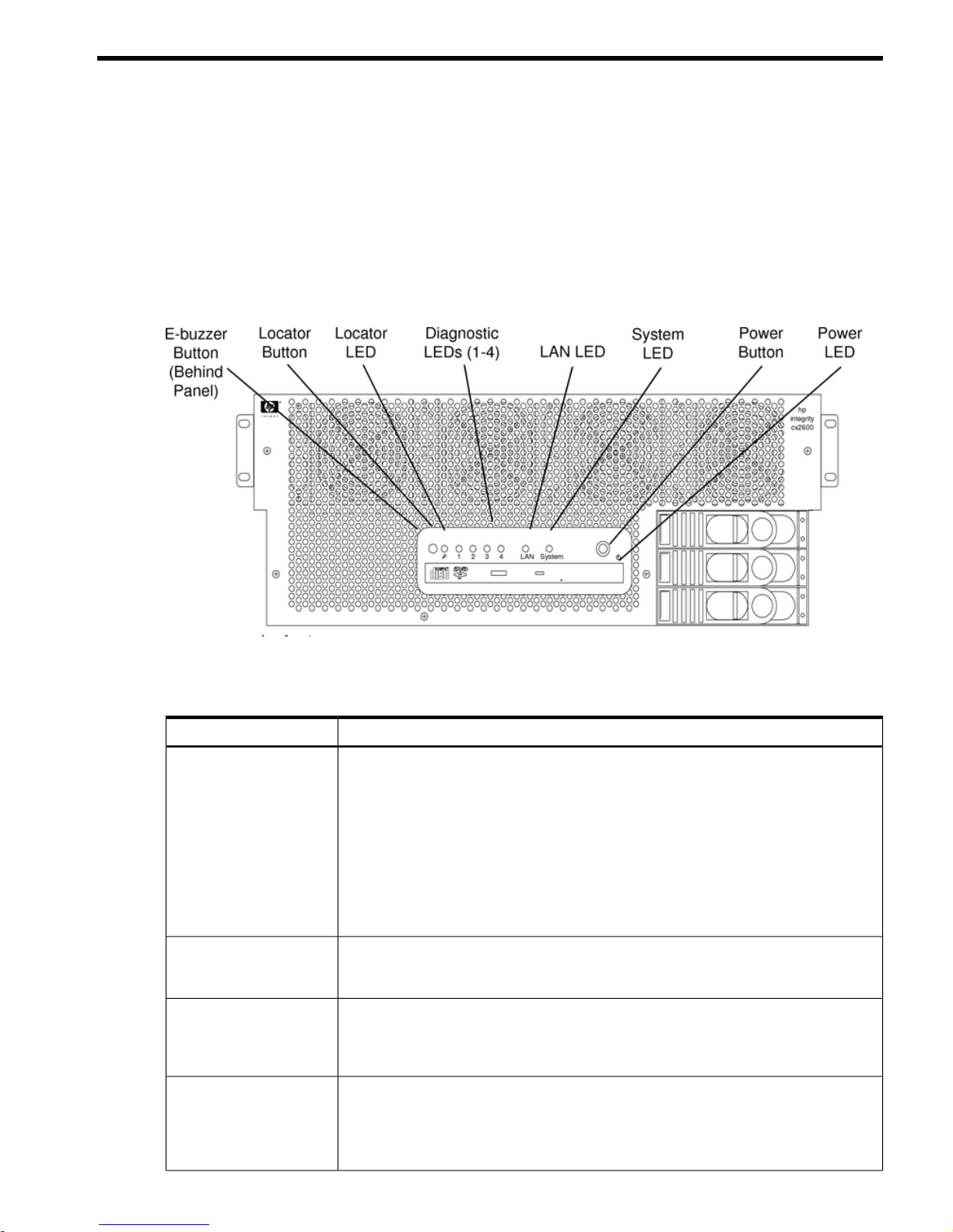
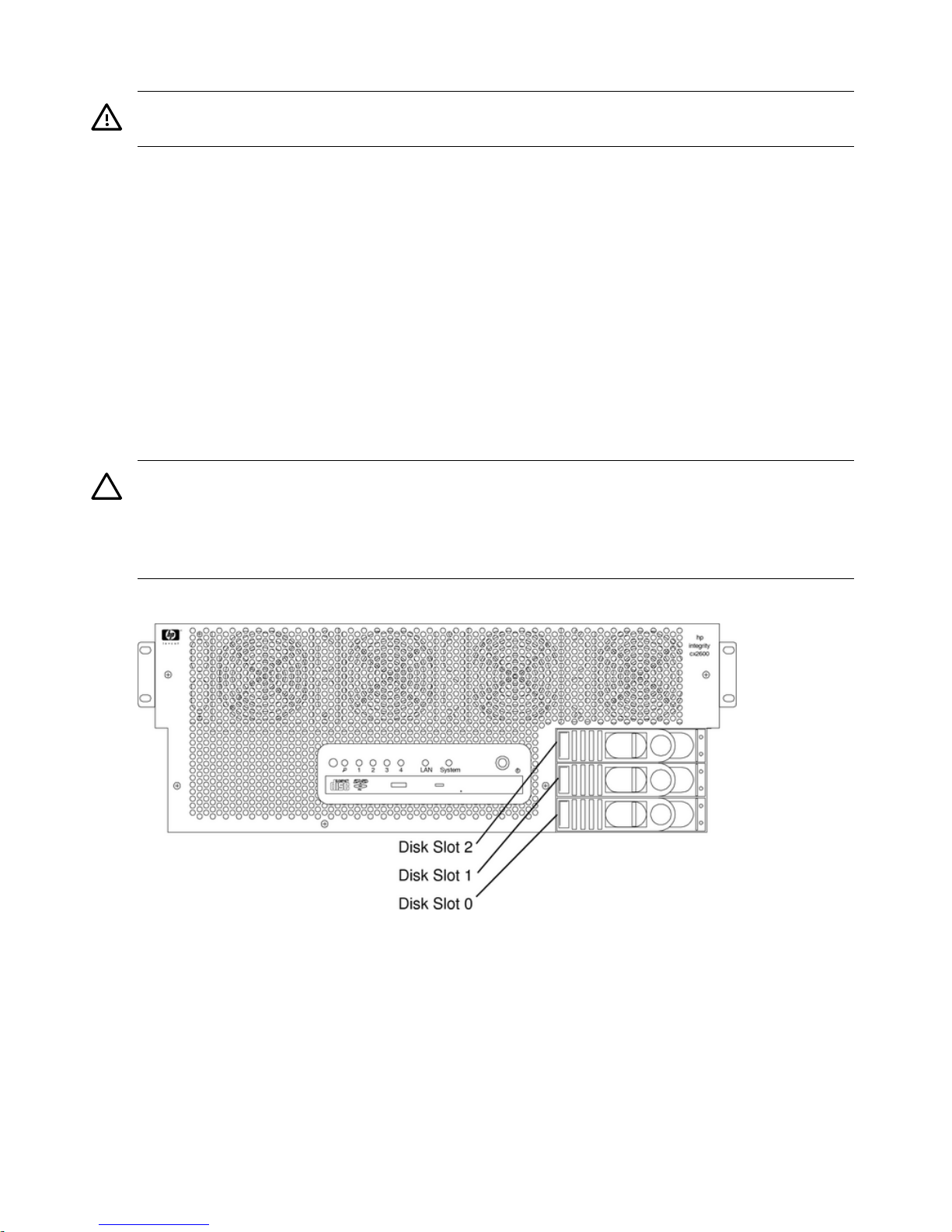
Figure 1-1 Front View of hp Integrity cx2600 Server
Switch/Button and LED Definitions
Table 1-1 Switch/Button and LED Definitions
DescriptionSwitch or Button
Sounds when an error has been detected during boot or operation.e-buzzer (behind front
grill)
One beep Processor absent or failing.
Two beeps Power supply malfunction.
Three beeps Memory malfunction.
Four beeps Management processor card malfunction.
Five beeps PCI I/O card malfunction.
Six beeps Critical system failure.
Seven beeps System board malfunction.
Remotely activate or deactivate the server locator LED through the LAN or locally by
pressing the Locator button onthe front or rear panel. This device isused to help identify
or locate a particular server among many.
Locator LED and Button
These LEDs, together with the server LED, display system error and fault status. The
states of the LEDs can be decoded to identify an error or fault condition or the failing
Diagnostic LEDs(1 thru 4)
customer repair unit (CRU). (For more information on LEDs, see “Troubleshooting”
(page 53).)
Shows the activity status of the server LAN as follows:LAN LED
OFF System power is off.
Lit steady green LAN link established but LAN is inactive.
Flashing green LAN is active.
Introduction 9
Page 10

Table 1-1 Switch/Button and LED Definitions (continued)
DescriptionSwitch or Button
Shows the server status as follows:System LED
Off Operating power is not available to the server.
Flashing amber at 1 Hz rate Attention required. Check the diagnostic LEDs
and the MP Status log for information. The LEDs
turn off when you access the MP log.
NOTE: Input power must be maintainedto both
power supplies (even those that have failed) for
LEDs to display accurate system faults.
Flashing red at a 2 Hz rate Fault detected. Check the diagnostic LEDs and
the MP status log for information. Turn off the
LED by using the MP dc command, or by
correcting the problem.
Flashing green at 0.5 Hz rate System is booting or running EFI.
Lit steady green System normal. The operating system is up and
running.
Controls the power supply (turns system power on or off) if power is available to the
power supply. (Controls both power supplies if two are installed.)
If power is off but available, pressing the Power button:
Power Button
1 - 3 seconds turns on the power supplies and applies power to the server.
3 - 5 seconds causes the e-buzzer to repeat the last stored error message (beep
code).
If power is on and the server is booting or executing an EFI function, pressing the Power
button:
1 - 3 seconds turns off the server power (hard power off).
3 - 5 seconds causes e-buzzer to repeat the last stored error message
(beep code).
5 seconds or longer turns off the server power (hard power off).
If power is on and the operating system is running, pressing the Power button:
1 - 3 seconds turns off system power (software-controlled power off).
3 - 5 seconds causes the e-buzzer to repeat the last stored error message
(beep code).
5 seconds or longer turns off system power (hard power off).
Shows system power status as follows:Power LED
Off Power is not available to the server.
Flashing green Standby power is available. Power supplies are off.
Lit steady green At least one power supply is operating normally.
Additional Controls and Indicators
Storage devices have additional LEDs that show their status.
Hot-Plug Disk Drive LEDs
The hot-swap disk drives have two LEDs per drive, as described below.
• Drive Status LED: The drive status LED is tri-color and may display green, amber, or yellow
at any given time. These colors indicate a normal, warning, or failure condition.
• Drive Activity LED: The drive activity LED is green and indicates disk drive activity. This
LED is controlled by the disk drive and turns on when a drive is accessed.
10 Controls, Ports, and Indicators
Page 11
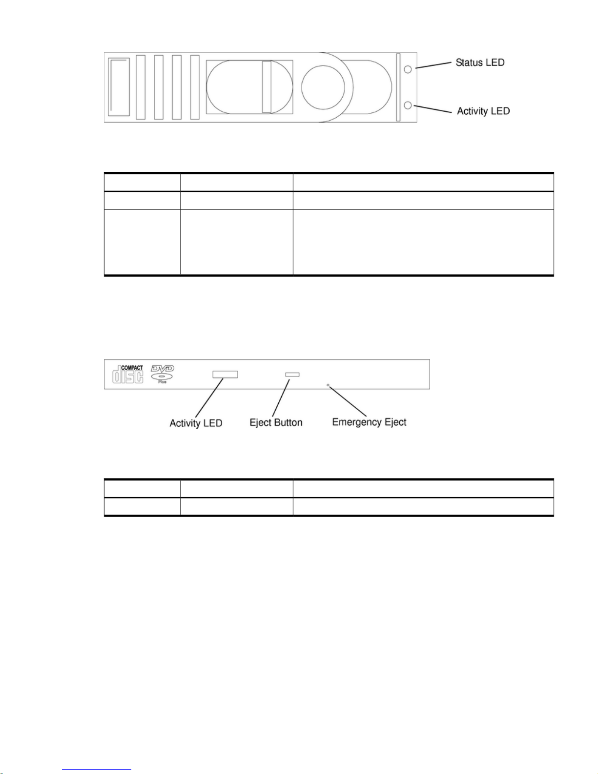
Figure 1-2 Hot-Swap Disk Drive LED Indicators
Table 1-2 lists the disk drive LED definitions.
Table 1-2 Hot-Swap Disk Drive LED Definitions
DescriptionColorLED
Drive access under hard drive control.Flashing greenActivity LED
Drive or slot normal (drive present).
Drive fault.
Green
Amber
Status LED
Missing MP card or missing jumper cable. For all HDD on SCSI
bus A or B.
Yellow
Blank
Pass through mode.
DVD/DVD-R/DVD-RW Drives
The server is delivered with one DVD-ROM drive. A CD/DVD-RW and DVD-RW are optional.
Each of these devices has one activity LED.
Figure 1-3 DVD Drive
Table 1-3 lists the DVD drive LED definitions.
Table 1-3 DVD Drive LED Definitions
DescriptionStateLED
Drive access under hard drive control.Flashing greenActivity LED
Rear Panel
The HP Server rear panel includes communication ports, I/O ports, two DC power supplies, and
the locator LED/button. LEDs visible on the rear panel of the HP Server signal the operational
status of:
• System management LAN
• Locator function
• Power supplies
• Gigabit LAN
• Management processor LAN
Introduction 11
Page 12
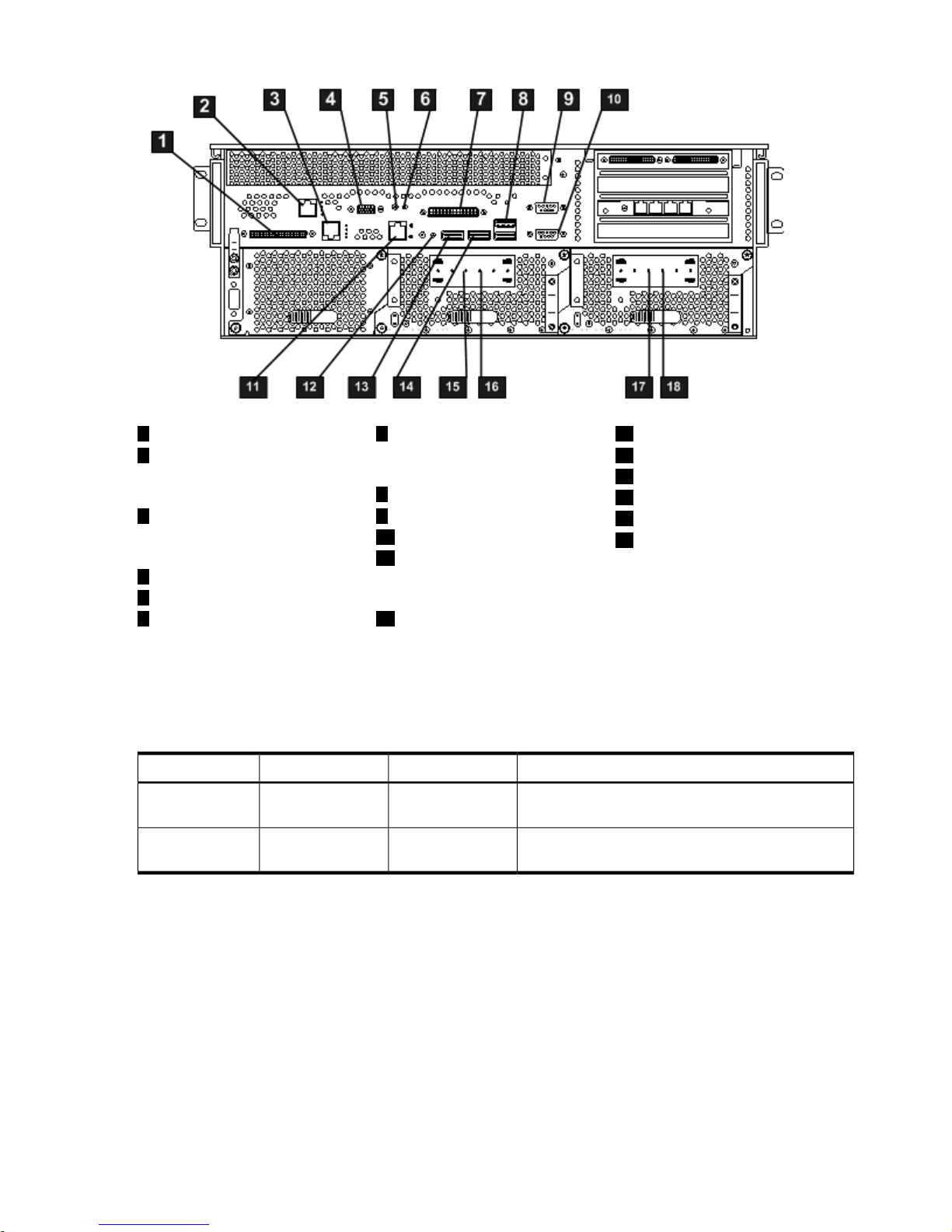
Figure 1-4 HP Integrity cx2620 Server Rear Panel
13
Keyboard USB Port
7
RS-232 MP Serial Console
Port (console, remote,
UPS)
1
LVD/SE SCSI Port
2 14
Management Processor
LAN (10/100 LAN) Port
and LEDs
Mouse USB Port
15
DC Power Supply Wire
8
USB Port
16
DC Power Supply Wire
3 9
Gigabit Ethernet LAN A
(10/100/1000 LAN) Port
and LEDs
Serial Port A (Console)
17
DC Power Supply Wire
10
Serial Port B
18
DC Power Supply Wire
11
System Management
LAN B (10/100/1000
LAN) Port and LEDs
4
MP VGA Port
5
MP Reset Button
126
TOC ButtonLocator Button and LED
10/100 System Management LAN LEDs
The two system management LAN LEDs display the status of the management LAN. The LEDs
are described in Table 1-4.
Table 1-4 Management Processor LEDs
StatusStateColorLED
Port is linked at 10 Mbps.
Port is linked at 100 Mbps.
Off
On
Yellow1. Speed
No link has been detected.
Port is linked.
Off
On
Green2. Activity
Locator LEDs and Button
Locator LEDs and buttons are provided on the front and rear panels of the server. The buttons
enable or disable the locator function. You can activate the locator LED from a remote location
through the LAN. The locator LED is lit to help call attention to locate the server when it is one
among many.
MP Reset and TOC Buttons
The MP Reset button resets the MP. The Transfer of Control (TOC) button halts all system
processing andI/O activity and restarts the computer system preserving system memory contents
and leaving the MP in communication with the console.
12 Controls, Ports, and Indicators
Page 13
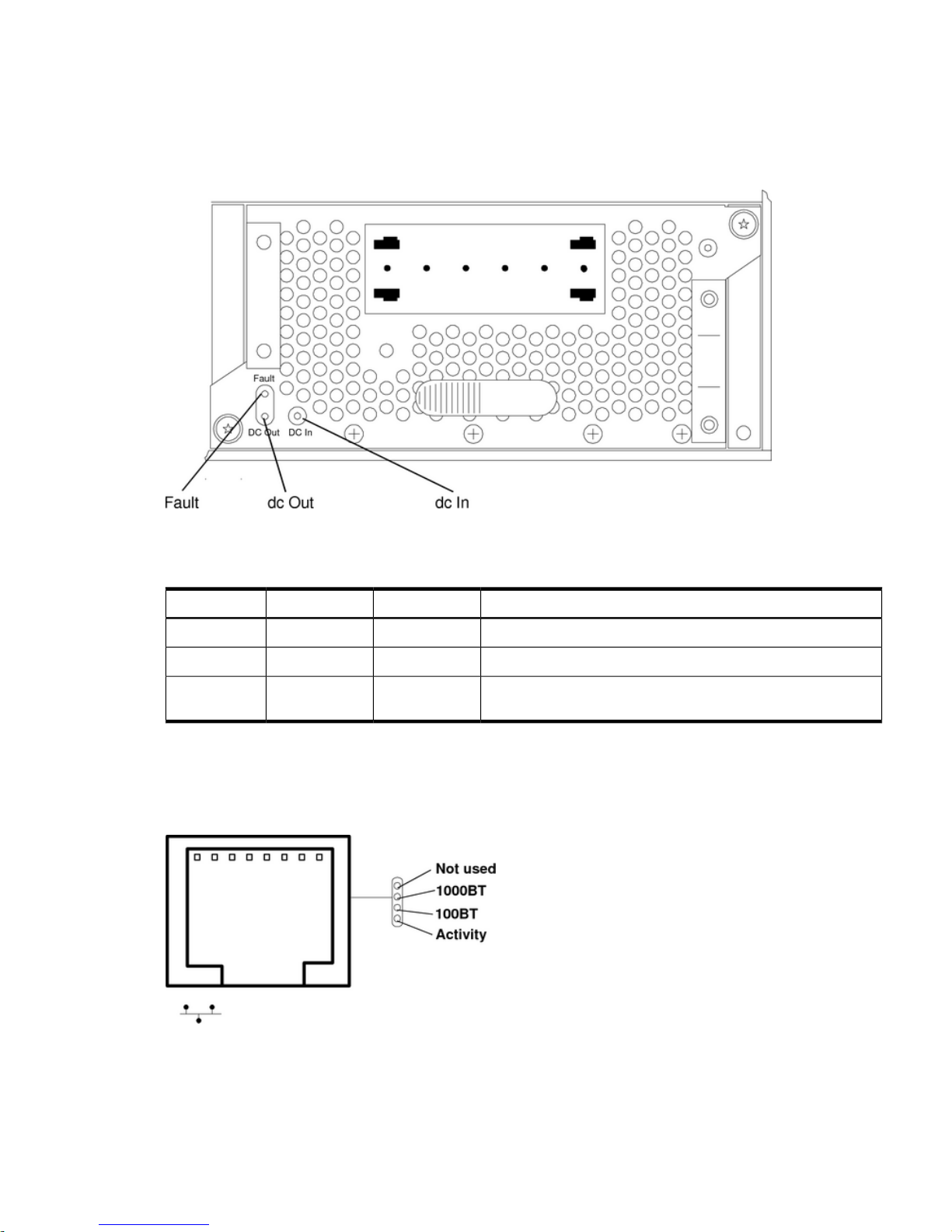
Power Supply Status LEDs
A power supply unit has three status LEDs located on the back of the power supply. Consolidated
status of two power supplies is reported by the front control panel by the power status LED. The
LEDs are described in Table 1-5.
Figure 1-5 Rear View of DC Power Supply
Table 1-5 lists and describes the power supply status LEDs.
Table 1-5 Power Supply Status LEDs
StatusStateColorLED
DC power (-40 to -72 VDC) is available to the power supply.OnGreenDC In
DC power is applied to system circuits.OnGreenDC Out
Power is applied to this power supply, and a fault has been
detected.
OffAmberFault
Gigabit LAN LEDs
The four Gigabit LAN LEDs display the status of the system LAN. The LEDs are described in
Figure 1-6 Gigabit 1 LAN LEDs
Introduction 13
Page 14

Table 1-6 Gigabit 10/100/1000 base-T Ethernet LAN A Status LEDs
StatusStateColorLocationLED
No 1000 Mbps link has been detected.
Port is linked at 1000 Mbps.
Off
On
GreenTop1. Gbit
No 100 Mbps link has been detected.
Port is linked at 100 Mbps.
Off
On
Green2nd from top2. 100 Mbit
No 10 Mbps link has been detected.
Port is linked at 10 Mbps.
Off
On
Green2nd from
bottom
3. Link
No LAN activity has been detected.
Flashing or lit solid indicates LAN activity.
Off
On
GreenBottom4. Activity
Management Processor LAN LEDs
The four management processor LAN LEDs display the status of the management LAN. The
LEDs are described in Table 1-7.
Table 1-7 Management LAN LEDs
StatusStateColorLocationLED
Self test is active.
Self test is active.
Off
On
YellowTopSelf Test
No Link detected or
100BT is active
Indicates 10BT LAN
activity.
Off
Flashing
Lit Steady
Green2nd from top10BT
10BT link established.
No Link detected or
10BT is active
Indicates 100BT LAN
activity.
Off
Flashing
Lit Steady
Green2nd from bottom100BT
100BT link
established.
Standby power is not
applied to
Off
On
GreenBottomStandby Power
management LAN
circuits.
Power is connected to
the server but the
server is not on.
System Board LEDs
There are three LEDs located on the system board that can be of assistance when troubleshooting.
These LEDs are located close to the rear of the server. View these LEDs through cooling holes
in the rear panel of the server. The LEDs are located as shown in Figure 1-7 and are described
in Table 1-8.
14 Controls, Ports, and Indicators
Page 15
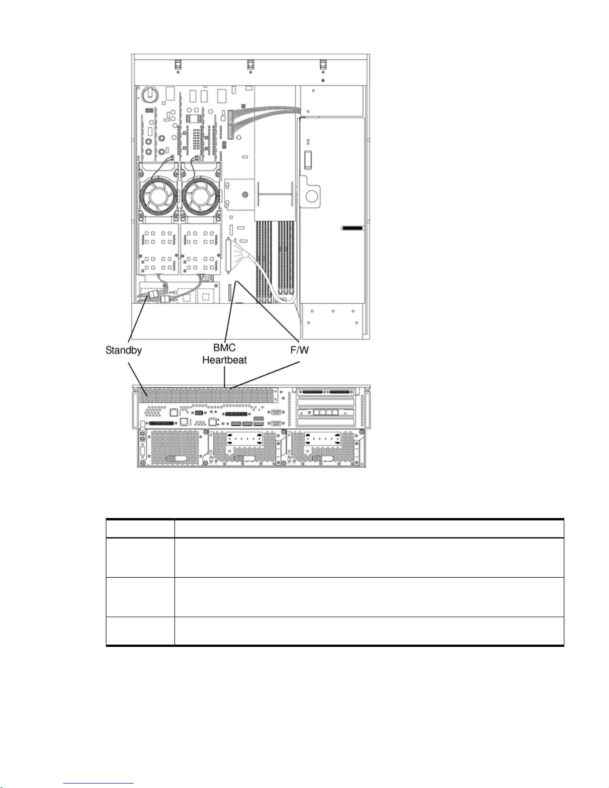
Figure 1-7 System Board LEDs
Table 1-8 lists the system board LEDs.
Table 1-8 System Board LEDs
DescriptionLED
The standby LED displays the power status of the server. It is lit when power is applied (DC In
LED on either power supply is lit). If power is applied and this indicator is off, you may have to
replace the system board.
Standby (STBY)
The baseboard management controller (BMC) heartbeat LED flashes whenever the BMC is active.
If this indicator is not blinking when the server is powered on (STBY LED is lit), you may have to
replace the system board.
BMC
The firmware LED lights when the boot process begins. If the server will not boot, and this LED
is off, you may have to replace the system board.
Firmware (F/W)
Management Processor Board LEDs
There are two LEDs located on the management processor (MP) board that may be of assistance
when troubleshooting. These LEDs are located close to the rear of the server and can be viewed
through cooling holes in the rear panel of the server. The LEDs are located as shown in Figure 1-8
and are described in Table 1-9.
Introduction 15
Page 16
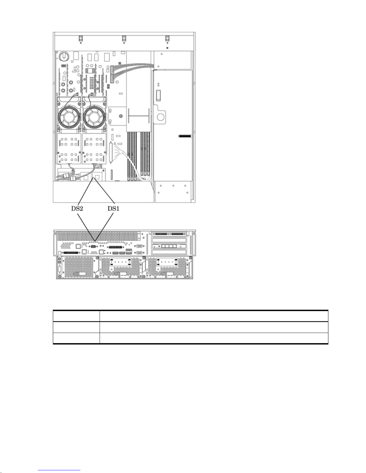
Figure 1-8 LEDs on Management Processor Board
Table 1-9 lists the MP card LEDs.
Table 1-9 Management Processor Board LEDs
DescriptionLED
This fault indicator flashes when an MP fault is detected.DS1
The MP heartbeat indicator flashes when the MP is active.DS2
16 Controls, Ports, and Indicators
Page 17
2 External Connectors
Connector Pinouts
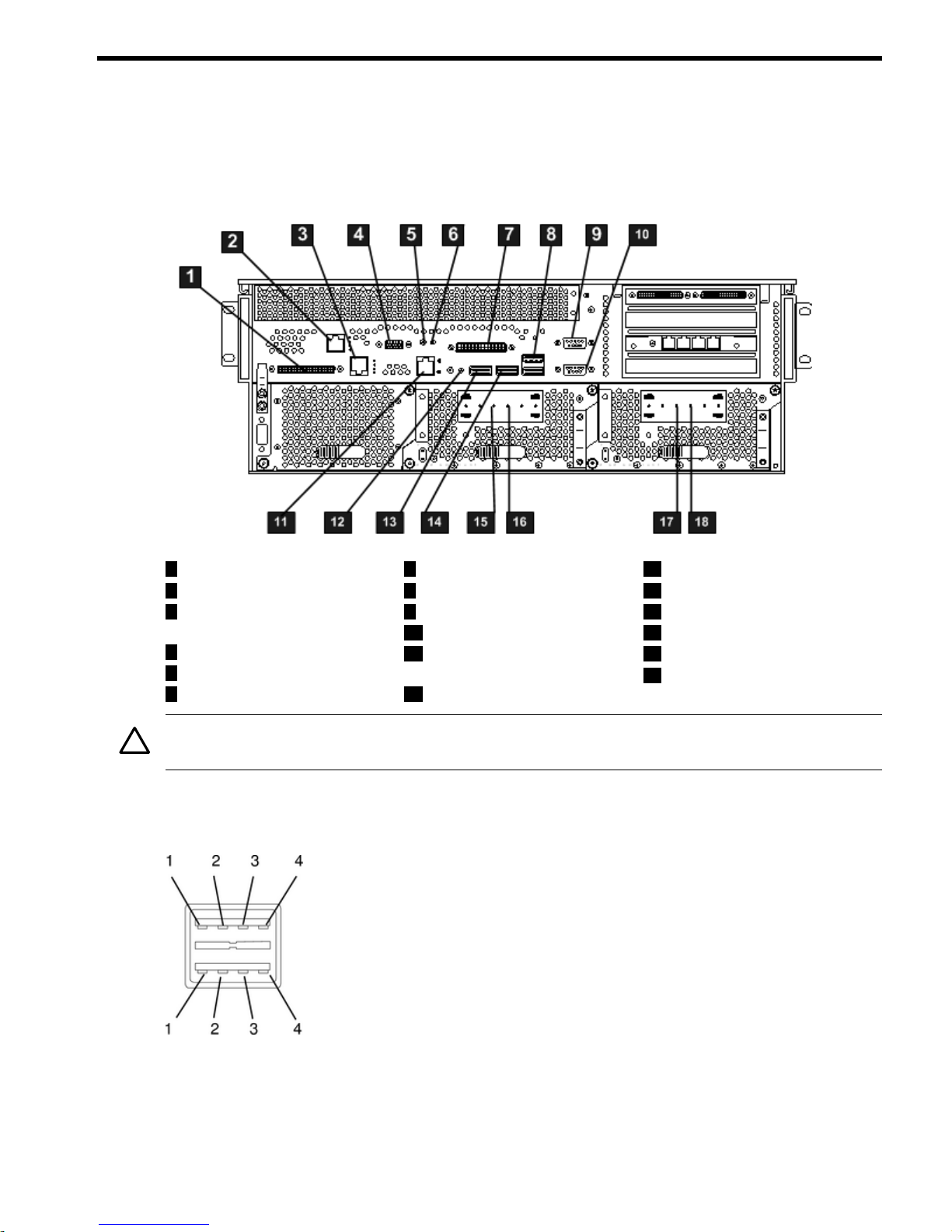
The following ports and connectors are found on the rear panel of the hp Integrity cx2600 Server.
Figure 2-1 Server Ports and Connectors
13
Keyboard USB Port
7
Console/Remote/UPS
1
LVD/SE SCSI Port
2
MP LAN Port
14
Mouse USB Port
8
USB Port
9
Serial Port A/Console
3
Gigabit Ethernet LAN
Port
15
DC Power Supply Wire
1610
DC Power Supply WireSerial Port B
4
MP VGA Port
1711
DC Power Supply WireSystem Management
10/100 LAN
5
MP Reset Button
18
DC Power Supply Wire
12
TOC Button
6
Locator Button and LED
CAUTION: To protect against intra-building lighting surges, use shielded cables that are
grounded at both ends. Failure to heed this caution can result in equipment damage.
Universal Serial Bus (USB) Ports
Figure 2-2 USB Port Connector
Connector Pinouts 17
Page 18
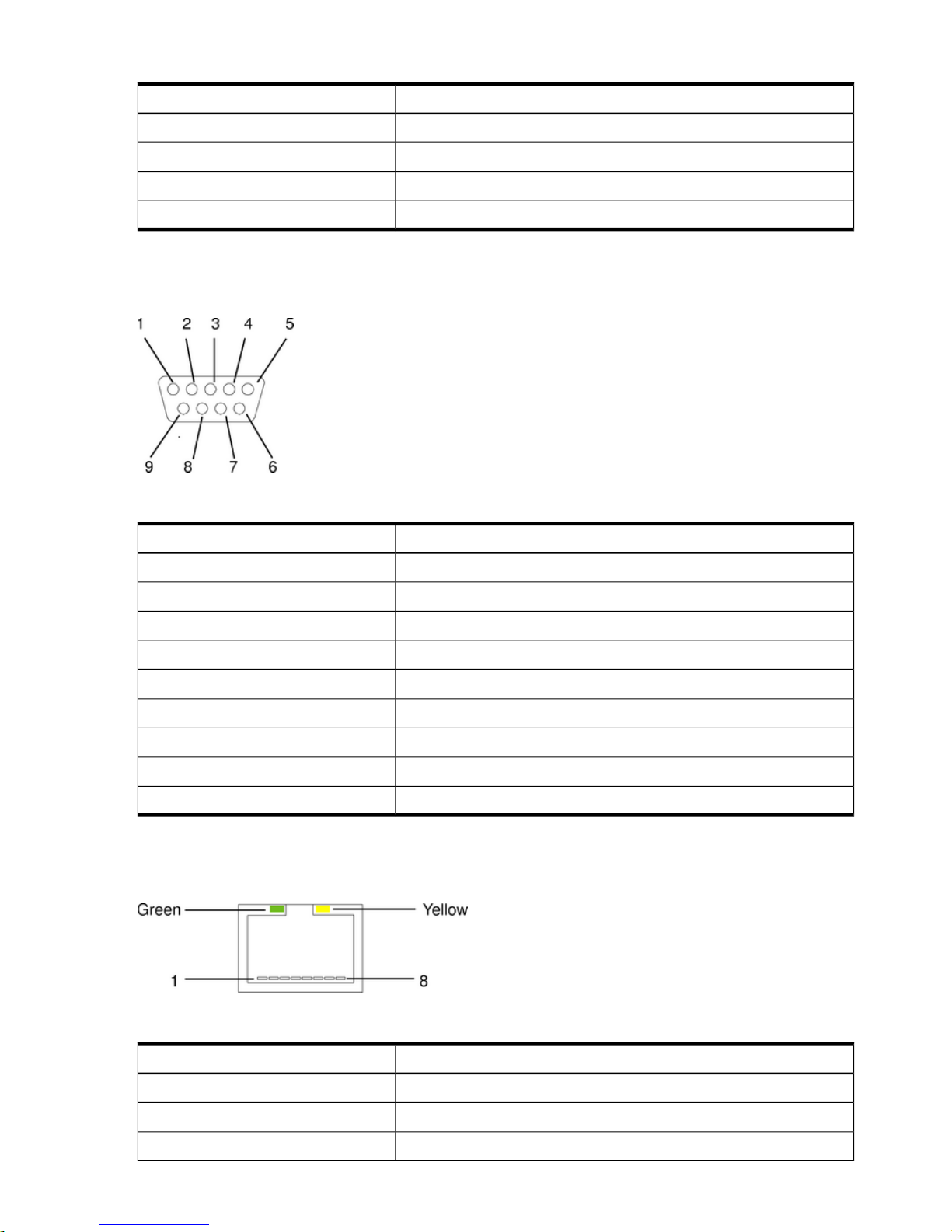
Table 2-1 USB Port Connector Pinouts
Signal DescriptionPin Number
+5VDC1
MR2
PR3
Ground4
Serial Ports
Figure 2-3 Serial Port Connector
Table 2-2 RS-232 Serial Console Port Pinouts
Signal DescriptionPin Number
Data carrier detect1
Receive data2
Transmit data3
Data Term ready4
Ground5
Ring indicator6
Clear to send7
Request to send8
Data set ready9
System Management LAN Port
Figure 2-4 System Management LAN Port
Table 2-3 System Management LAN Port Pinouts
Signal DescriptionPin Number
TXP1
TXN2
RXP3
18 External Connectors
Page 19
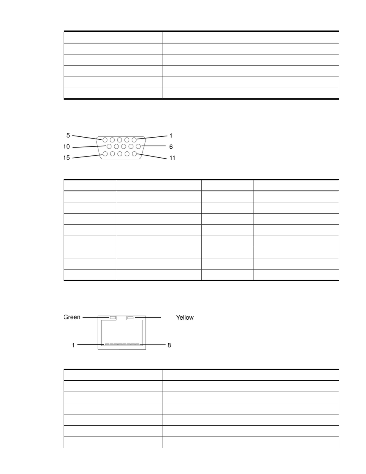
Table 2-3 System Management LAN Port Pinouts (continued)
Signal DescriptionPin Number
Not used4
Not used5
RXN6
Not used7
Not used8
Management Processor VGA Port
Figure 2-5 MP VGA Port
Table 2-4 MP VGA Port Pinouts
Signal DescriptionPin NumberSignal DescriptionPin Number
+5 VDC9Red1
Sync return (ground)10Green2
Not used11Blue/RXP3
Monitor ID bit 112Not used4
Horizontal sync (+)13Video self test (ground)5
Vertical sync (–)14Red return (ground)6
Video ID bit 215Green return (ground)7
Blue return (ground)8
Gigabit Ethernet (LAN) and MP LAN Port
Figure 2-6 Gigabit LAN/MP LAN Port
Table 2-5 Gigabit LAN Port Pinouts
Signal DescriptionPin Number
TXP1
TXN2
RXP3
Not used4
Not used5
RXN6
Connector Pinouts 19
Page 20
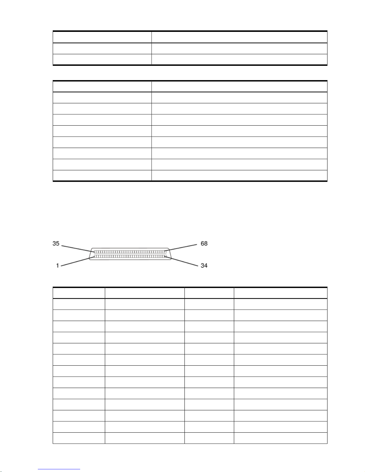
Table 2-5 Gigabit LAN Port Pinouts (continued)
Signal DescriptionPin Number
Not used7
Not used8
Table 2-6 MP LAN Port Pinouts
Signal DescriptionPin Number
TXP1
TXN2
RXP3
Not used4
Not used5
RXN6
Not used7
Not used8
SCSI Port, Ultra 3, 68-Pin
Two Ultra 3, 68-pin SCSI connectors are located on the host bus adapter (HBA) located in PCI
slot 1. The upper connector supports SCSI channel A and the lower connector supports SCSI
channel B.
Figure 2-7 SCSI Port, Ultra 3, 68-Pin
Table 2-7 SCSI Port Pinouts
Signal DescriptionPin NumberSignal DescriptionPin Number
S35 (–DB 12)35S1 (+DB 12)1
S36 (–DB 13)36S2 (+DB 13)2
S37 (–DB 14)37S3 (+DB 14)3
S38 (–DB 15)38S4 (+DB 15)4
S39 (–DB P1)39S5 (+DB P1)5
S40 (–DB 0)40S6 (+DB 0)6
S41 (–DB 1)41S7 (+DB 1)7
S42 (–DB 2)42S8 (+DB 2)8
S43 (–DB 3)43S9 (+DB 3)9
S44 (–DB 4)44S10 (+DB 4)10
S45 (–DB 5)45S11 (+DB5)11
S46 (–DB 6)46S12 (+DB 6)12
S47 (–DB 7)47S13 (+DB 7)13
20 External Connectors
Page 21

Table 2-7 SCSI Port Pinouts (continued)
Signal DescriptionPin NumberSignal DescriptionPin Number
S48 (–DB P)48S14 (+DB P)14
S49 (GND)49S15 (GND)15
S50 (GND)50S16 (DIFFSENS)16
S51 (TERMPWR)51S17 (TERMPWR)17
S52 (TERMPWR)52S18 (TERMPWR)18
S53 (RESERVED)53S19 (RESERVED)19
S54 (GND)54S20 (GND)20
S55 (–ATN)55S21 (+ATN)21
S56 (GND)56S22 (GND)22
S57 (–BSY)57S23 (+BSY)23
S58 (–ACK)58S24 (+ACK)24
S59 (–RST)59S25 (+RST)25
S60 (–MSG)60S26 (+MSG)26
S61 (–SEL)61S27 (+SEL)27
S62 (–C/D)62S28 (+C/D)28
S63 (–REQ)63S29 (+REQ)29
S64 (–I/O)64S30 (+I/O)30
S65 (–DB 8)65S31 (+DB 8)31
S66 (–DB 9)66S32 (+DB 9)32
S67 (–DB 10)67S33 (DB 10)33
S68 (–DB 11)68S34 (DB 11)34
Connector Pinouts 21
Page 22
3 Installing Additional Components
Safety Information
This chapter describes installing additional or optional hardware to your hp Integrity cx2600
Server.
Follow the procedures listed below to ensure safe handilng of components and to prevent harm
to both you and the HP Server:
• Use an antistatic wrist strap and a grounding mat, such as those included in the Electrically
Conductive Field Service Grounding Kit (HP 9300-1609).
• Handle accessory boards and components by the edges only. Do not touch any metal-edge
connectors or any electrical components on accessory boards.
• Do not wear clothing that is subject to static charge build-up, such as wool or synthetic
materials.
WARNING! Hazardous energy is present inside the HP Server. Always remove power from
the server before working inside the unit. Serious injury may result if this warning is not observed.
Service Tools Required
The HP Integrity cx2620 server may require one or more of the following tools for service:
• Electrically Conductive Field Service Kit (P/N 9300-1609)
• 1/4 inch flat blade screwdriver
• ACX-15 Torx screwdriver
• ACX-10 Torx screwdriver
• IPF CPU install tool (P/N 5069-4551—supplied with processors shipped separately)
Accessing a Rack-Mounted Server
The HP Integrity cx2600 server is designed to be rack-mounted. The following procedure explains
how to gain access to a server that is mounted in an approved rack.
WARNING! Ensure that all anti-tip features (front and rear anti-tip feet installed; adequate
ballast properly placed, and so on) are employed prior to extending the server.
Installing Components When the Server Is in a Rack
Power supplies, fans, and disks can be installed when the server is fully inserted into a rack.
Only front and rear access is required.
Internal components can be accessed by removing the top cover. Proceed as follows:
WARNING! Hazardous energy is present inside the HP Server. Always remove power from
the server before working inside the unit. Serious injury may result if this warning is not observed.
NOTE: Ensure that there is enough area (approximately 1.5 meters [5 ft.]) to fully extend the
server out the front of the rack to work on it.
1. Turn off and disconnect the system power. Disconnect power at the DC source end of the
power cables, using the disconnect device that is part of the rack or facility power system.
2. Label and disconnect all cables from the unit rear panel connectors.
3. Remove or loosen (as appropriate) the screws that fasten the server to the rack.
4. If the server is slide-mounted, slowly pull the chassis forward (or push from the rear) to
extend the chassis from the rack. The server is fully extended when the rail clips are locked
22 Installing Additional Components
Page 23
in place. If the server is tray-mounted, it is not held in the rack and can fall from its mounting.
Do not extend the server from the rack, remove it from the rack for internal access.
5. Remove the top cover. See “Removing the Top Cover” (page 29).
Removing the Server From a Rack
WARNING! Do notattempt to lift the server alone. The server can weigh as much as 32 kilograms
(70 lbs.). Serious injury may result if this warning is not observed.
NOTE: Ensure there is enough area (approximately 1.5 meters [5 ft.]) to fully extend the server
from the front of the rack to work on it.
To remove the server from the rack, follow these steps:
1. Turn off and disconnect system power. Disconnect power at the DC source end of the power
cables, using the disconnect device that is part of the rack or facility power system.
2. Label and disconnect all cables from the unit rear panel connectors.
3. Remove or loosen (as appropriate) the screws that fasten the server to the rack.
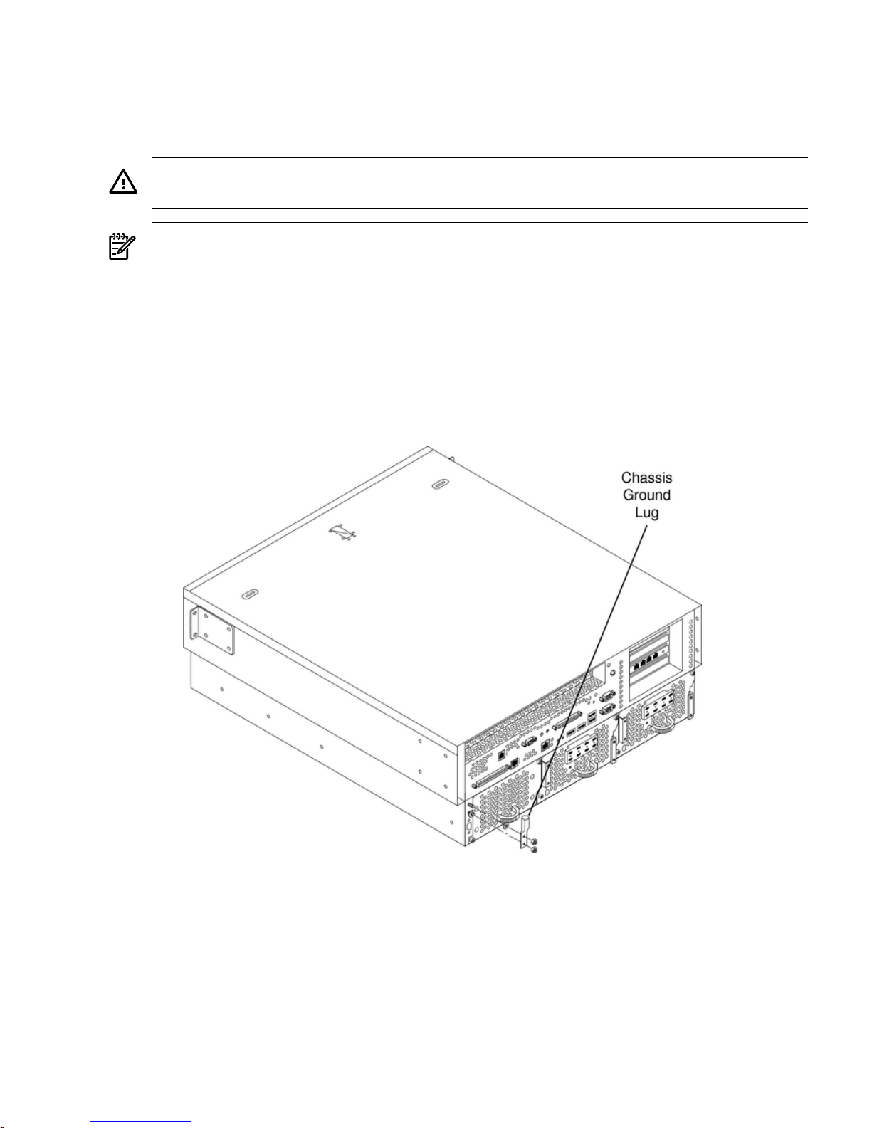
4. Label and disconnect the rack or facility ground cable from the chassis rear panel (Figure 3-1).
Figure 3-1 Chassis Ground Lug
5. If the server is slide-mounted, slowly pull the chassis forward (or push from the rear) to
extend the chassis from the rack. The server is fully extended when the rail clips are locked
in place. Do not extend tray-mounted servers. Tray-mounted servers are not locked in place
and can fall if extended from a rack.
6. Disengage the slides or mounting hardware and take the server to a static-free work station.
Accessing a Rack-Mounted Server 23
Page 24
Install the Server into a Rack
WARNING! Do notattempt to lift the server alone. The server can weigh as much as 32 kilograms
(70 lbs.). Serious injury may result if this warning is not observed.
To insert the server into the rack, follow these steps:
1. Engage the server slides or mounting kit, as appropriate.
2. Slide the server inward and push the server into the rack until it is in position.
3. Connect server cables to rear panel connectors.
4. Connect the rack/facility ground cable to chassis ground lug.
5. Replace or tighten (as appropriate) the screws that fasten the server to the rack.
Installing Disk Drives
The supported configuration of a server includes one, two, or three Low-Voltage-Differential
(LVD), hot-plug disk drives. If any of the three disk drives are not installed, you must install a
disk filler in the disk location.
Hot-plug disk drives are located at the front of the server. The following sections describe how
to install a hot-pluggable disk drive.
CAUTION: A hot-plug device may require interaction with the operating system before the
device can be safely removed from or installed into the server. Determine if the operating system
supports replacement of disk drives while the operating system is running. If the operating
system does not support this feature, shut down the operating system before performing these
procedures. Failure to observe this caution could result in system failure.
Figure 3-2 Front View of hp Integrity cx2600 Server
Removing Hot-Plug Disk Drives
Slots are provided for up to three hot-plug disk drives in your hp Integrity cx2600 Server. When
disk drives are not installed, filler assemblies are installed to prevent air leakage and ensure
adequate cooling.
24 Installing Additional Components
Page 25
NOTE: The filler assemblies are removed and installed in the same manner as described for
hard drives. Simply pull the dummy release lever to pull the filler from the server.
When inserting a filler, push the filler into position.
To remove a hot-plug disk drive, perform the following steps:
CAUTION: The disk drives in the server are not hot-swappable: they are merely hot-pluggable.
A manual software procedure may be required to safely remove or insert disk drives while the
server is running. To avoid damage to the hard drives:
• Refer to the documentation provided with the disk drive for additional information about
removing and inserting a drive.
• Refer to the operating system documentation for additional information about removing
and inserting hot-plug assemblies.
1. If required (OS does not support hot-plugging devices), stop the operating system.
2. Squeeze inward on the release clip and pull the release lever to pull the drive from the server
chassis.
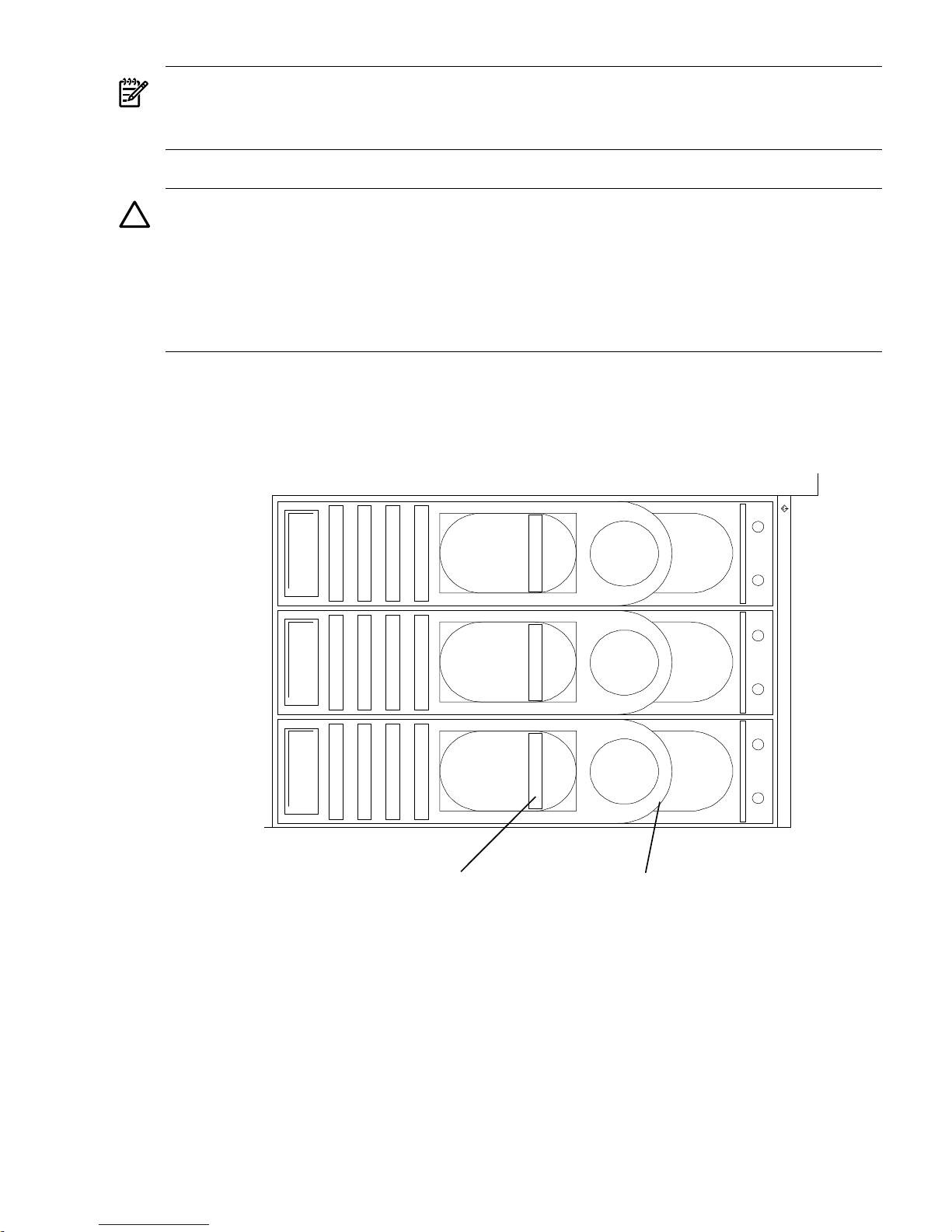
Figure 3-3 Disk Drives in Server
dskdrvfrnt1
2
1
0
S
C
S
I
Release
Clip
Release
Lever
Installing Hot-Plug Disk Drives
Up to three hot-plug disk drives can be installed in your hp Integrity cx2600 Server. Always use
low profile disk drives (1.0" height) in your server.
To install a hot-plug disk drive, follow these steps:
1. If required, (OS does not support hot-plugging) stop the operating system.
2. If a disk filler is installed, remove it by pulling the dummy release lever.
3. With the release lever pulled out, slide a hot-plug hard disk into the disk slot until it is
seated.
Installing Disk Drives 25
Page 26
4. Press the release lever until it is flush with the front of the server. The release lever clicks as
it locks into position.
5. If the operating system was stopped in step Step 1, reset the system to the EFI Boot
Maintenance Menu to rescan the hard drives.
6. If the operating system was stopped in step Step 1, use the EFI Shell map command to verify
that you correctly installed the newly inserted drive. Refer to “Troubleshooting” (page 53)
and “Utilities” (page 73), for information about connecting a console andusing the EFI shell.
Installing Hot-Swap Power Supply Units
The supported configuration of the hp Integrity cx2600 Server requires that two power supplies
be installed. During normal operations, the two power supplies share the load. Each provides
power through a separate power rail. A single power supply can provide all power needed for
normal operations, but a second power supply is installed to provide backup capability.
Hot-swappable power supplies 1 and 2 are located at the rear of the chassis. The power supplies
are identical and interchangeable.
NOTE: A hot-swappable device does not require interaction with the operating system before
the device is removed from or installed into the server. If the second power supply is functioning
correctly, you can power off and remove a power supply with no effect on server operations.
The power to the server (other power supply) does not have to be off to remove or replace a
hot-swap power supply.
Removing and Replacing a Hot-Swap Power Supply
A power supply can be replaced while the server is installed in a rack, with the server operating
normally. Removal and installation of a power supply will have no effect on operations if the
other power supply is functioning correctly.
To install a hot-swap power supply, follow these steps:
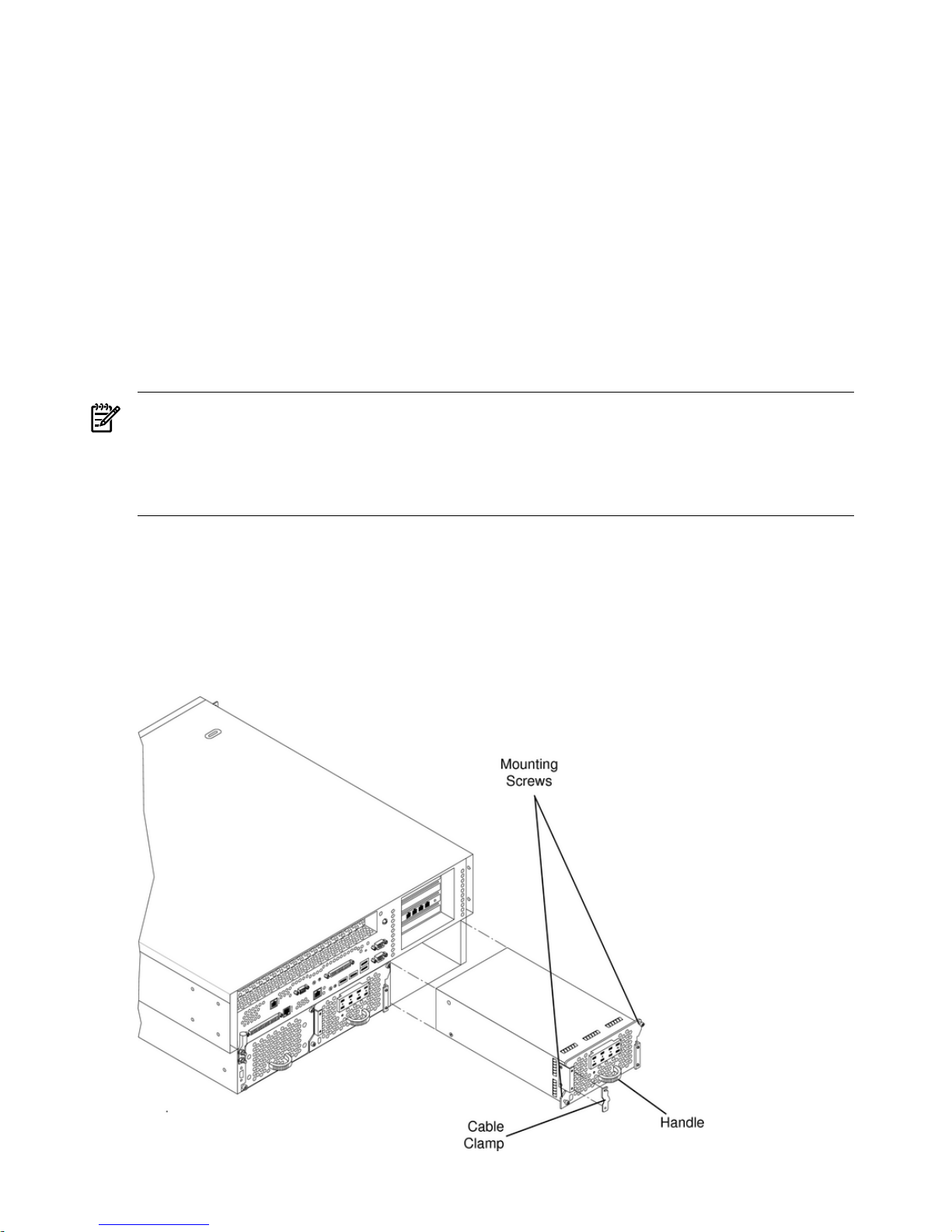
Figure 3-4 Removing a Hot-Swap Power Supply
26 Installing Additional Components
Page 27
1. If rack-mounted, you mayneed to extend a slide-mounted server out from the rack for better
access. If necessary, slide the server out to the fully extended position.
2. Remove power from the power supply being replaced. Disconnect power at the DC source
end of the power cable, using the disconnect device that is part of the rack or facility power
system.
3. Loosen the two knurled knobs on the power-supply cable clamp to release the power feed
leads.
4. Press up on the two lower tabs of the terminal barrier strip cover to snap off the cover.
WARNING! Always check that the power cable is not connected to a power source before
attempting to disconnect the power cable from power supply terminals. Failure to heed this
warning could result in injury.
5. Loosen or remove (as appropriate) the screws that secure power cable leads to the terminal
strip and disconnect the power cable leads from the power supply.
6. Reinstall the terminal strip hardware and barrier strip cover (removed in steps 4 and 5) to
prevent loss. Hang the cover on the upper tabs and snap the cover into place.
7. Using an ACX-15 torx screwdriver, loosen the two captive mounting screws that secure the
power supply to the server chassis.
8. Pull the power supply from the server chassis by pulling the curved handle.
9. Orient the power supply such that the securing screws are aligned with the corresponding
holes in the server chassis. Gently push the power supply into position.
10. When the power supply is fully inserted into the server chassis, tighten the two mounting
screws to secure the power supply in place.
11. Press up on the two lower tabs on the terminal barrier strip cover to snap off the cover.
WARNING! Always check that the power cable is not connected to a power source before
attempting to connect the power cable to power supply terminals. Failure to observe this
warning can result in injury.
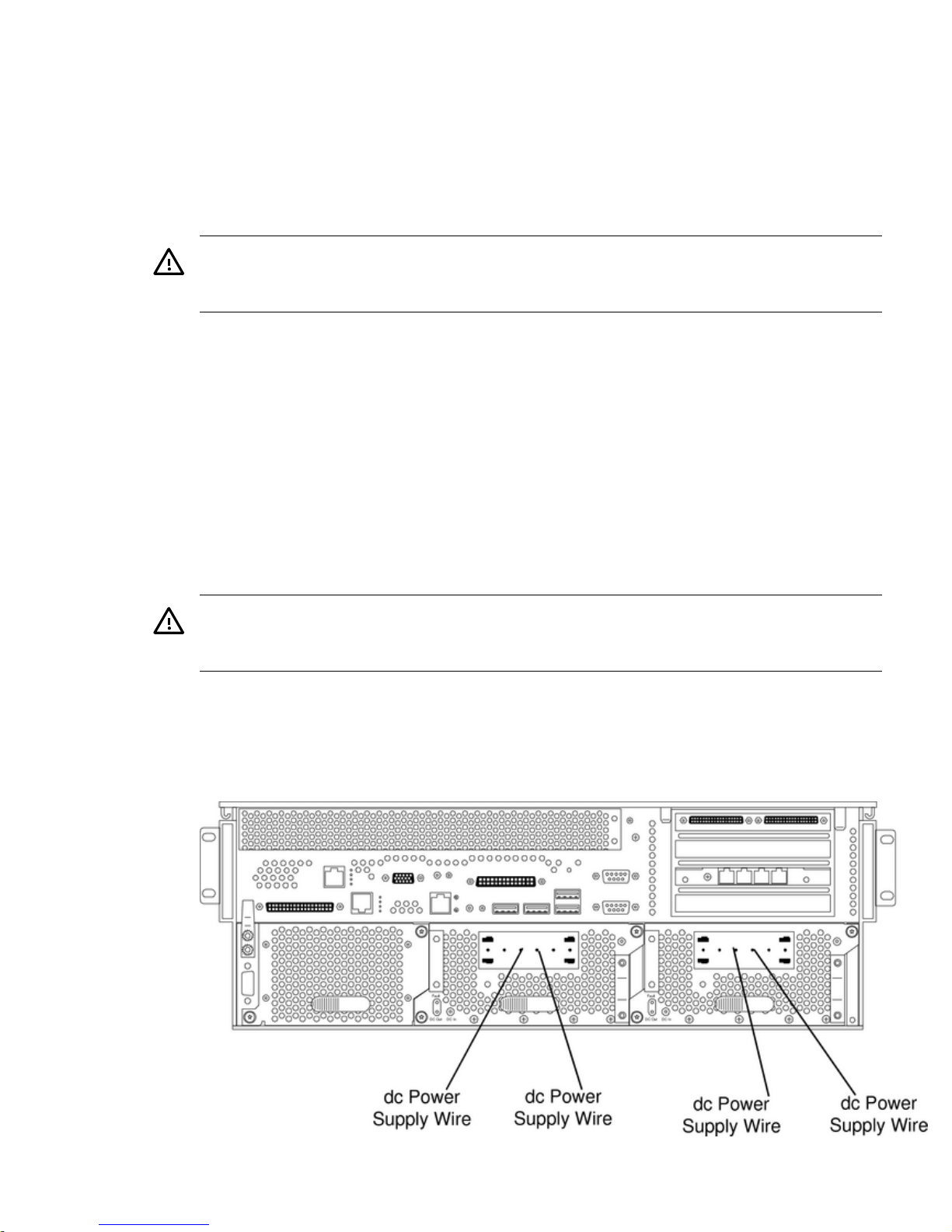
12. Connect the power cable leads to the power supply terminals (Figure 3-5).
For -48V, the most positive wire is 0V.
For -48V, the most negative wire is -48V.
Figure 3-5 DC Power Supply Wire Connectors
Installing Hot-Swap Power Supply Units 27
Page 28
13. Install the terminal barrier strip cover (removed in step 11). Hang the cover on the upper
tabs and snap the cover into place.
14. Route the power cable through the power supply cable clamp and tighten the two knurled
knobs to secure the cable in place.
15. Connect the power cable to the DC power source.
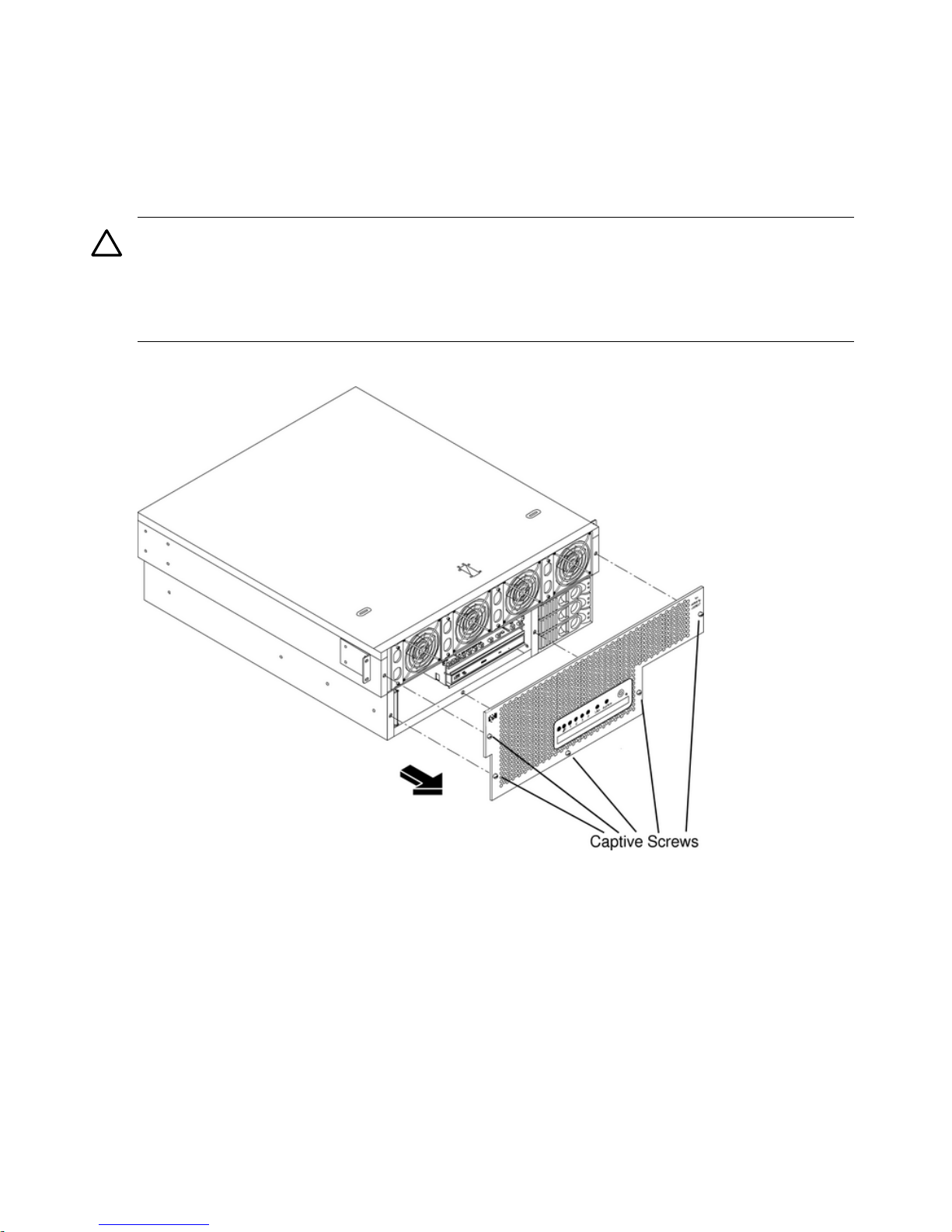
Installing the Front Grill and Top Cover
CAUTION: Operation of the server without the front grill and top cover in place makes the
server susceptible to electromagnetic interference (EMI) and overheating problems, which can
result in system failure. Keep the front grill and top cover in place during normal operation.
Observe all electrostatic discharge (ESD) safety precautions while performing this procedure.
Failure to follow ESD safety precautions can result in damage to the server.
Figure 3-6 Removing the Front Grill
Removing the Front Grill
You must remove the front grill for access to the front mounted fans or the optical drive. To
remove the front grill, perform the following steps:
To remove the front grill, follow these steps:
1. Use the ACX-15 Torx screwdriver to loosen the five captive screws that secure the grill to
the chassis.
2. Pull the grill from the front of the server chassis.
Installing the Front Grill
To install the front grill, follow these steps:
1. Hold the grill against the front of the server chassis in mounting position.
2. Tighten the five captive screws to secure the grill to the server chassis (Figure 3-6).
28 Installing Additional Components
Page 29
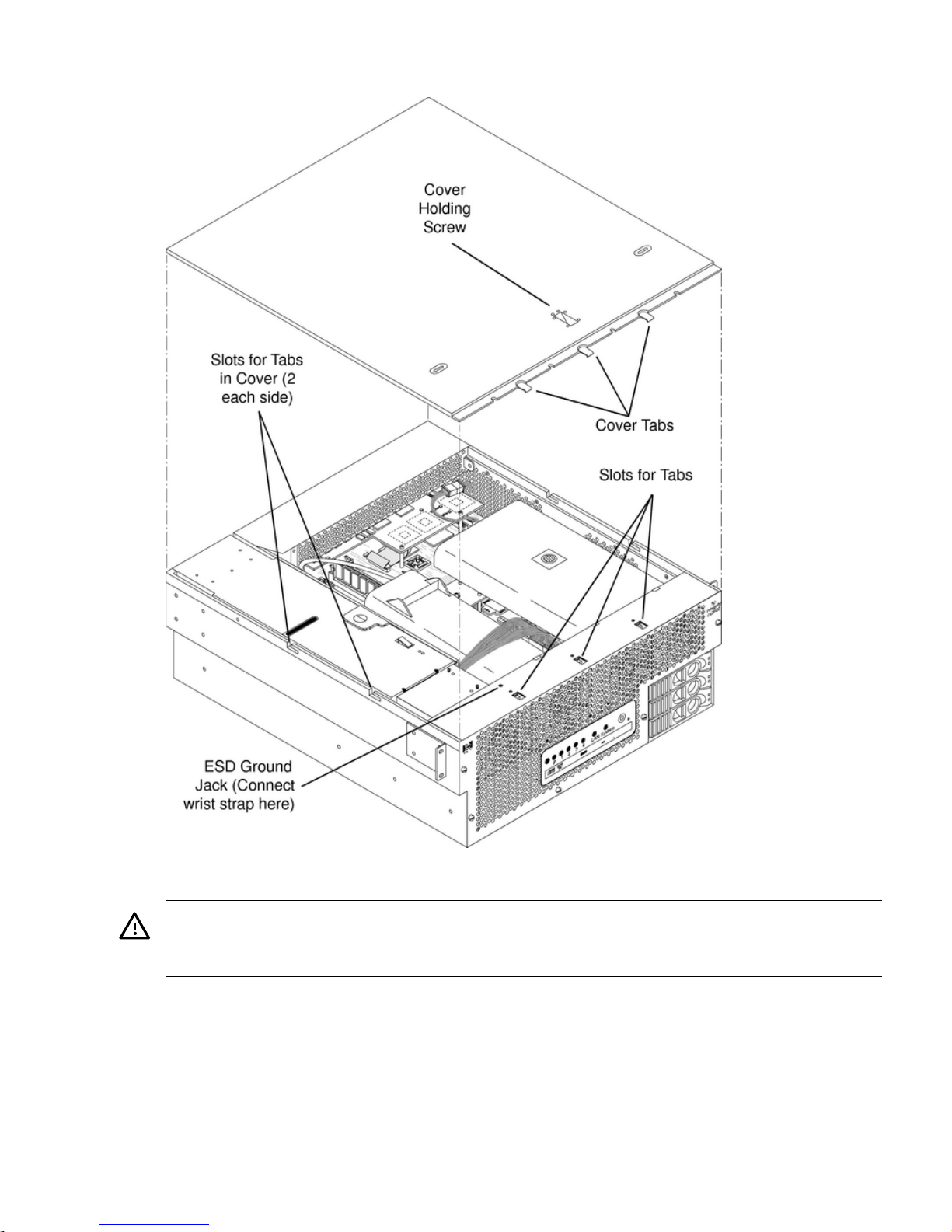
Removing the Top Cover
To remove the top cover, follow these steps:
WARNING! Hazardous voltages are present within the server when power is applied. Do not
remove the server top cover without first turning off and disconnecting power. Always replace
the top cover before turning the system on.
1. Power off and disconnect system power. Disconnect power at the DC source end of the
power cables, using the disconnect device that is part of the rack or facility power system.
2. Slide the server out from the rack until it stops. See “Accessing a Rack-Mounted Server”
(page 22).
3. Remove the server from the rack and place it on an ESD-protected work surface. See
“Removing the Server From a Rack” (page 23).
4. Use the ACX-15 Torx screwdriver to loosen the captive screw that holds the top cover in
place.
Installing the Front Grill and Top Cover 29
Page 30

5. Slide the cover toward the rear of the server chassis and lift it straight up.
Installing the Top Cover
To install the top cover, follow these steps:
1. Align each pair of tabs on the left and right sides of the cover with the corresponding slots
in the chassis. Set the cover in place on the chassis.
2. Align the three tabs on the front of the cover with the corresponding apertures at the top
front of the chassis and insert the tabs into the slots.
3. Push the cover forward until it seats on the chassis.
4. Tighten the captive screw to secure the cover in place.
Installing Hot-Swap Chassis Fan Units
There are five hot-swappable chassis fan units in the HP server. Fan units 1, 2, 3 and 4 are
accessible from the front of the chassis. Fan unit 5 is accessible from the rear of the chassis. Fan
units 1, 2, 3 and 4 are identical and interchangeable.
If a fan failure is total (both rotors), or if the fan has been removed from the chassis for more than
30 seconds, the system logs the event as a critical error. A critical error causes the system LED
to flash red, and requires a reboot to reset the error status. A total fan failure (including removal)
for more than two minutes results in system shutdown. If you are hot-swapping a fan assembly
in response to an error message, and the system is operating normally, hot-swapping the fan in
30 Installing Additional Components
Page 31

less than 30 seconds eliminates the requirement for a system reboot. Hot-swapping a fan in less
than two minutes enables continued operation and prevents automatic shutdown.
CAUTION: Operating the server with the front grill removed risks EMI. Operate the server
with the front grill removed only when hot-swapping a fan. Always replace the front grill
immediately after replacing a fan.
Observe all ESD safety precautions while performing this procedure. Failure to follow ESD safety
precautions can result in damage to the server.
NOTE: A hot-swap device does not require interaction with the operating system before the
device is removed from or installed into the server.
The power to the server does not have to be off to remove or replace a hot-swappable chassis
fan unit.
Removing and Installing a Front Panel Hot-Swap Fan
Figure 3-7 Removing a Front Panel Hot-Swappable Fan
The server does not need to be removed or extended from the rack to enable fan replacement.
Installing Hot-Swap Chassis Fan Units 31
Page 32

To removeand install a hot-swappable fan from the front of the server chassis, follow these steps:
CAUTION: Hot-swapping a fan can interrupt system operation.
If you are hot-swapping a fan assembly in response to an error message, and the system is
operating normally, hot-swapping the fan in less than 30 seconds eliminates the requirement for
a system reboot.
Hot-swapping the fan in less than two minutes enables continued operation and prevents
automatic shutdown.
1. Remove the front grill. See “Removing the Front Grill” (page 28).
2. Use the ACX-15 Torx screwdriver to loosen the two captive screws on the plastic fan extractor
handle (left side of fan) (Figure 3-7).
3. Using the extractor handle, pull the fan from the server chassis.
4. Orient the replacement fan so that the extractor handle is on the left. Insert the fan into the
chassis opening and press it firmly into place.
5. Tighten the two captive screws that secure the fan in place.
32 Installing Additional Components
Page 33

Removing and Installing a Rear Panel Hot-Swappable Fan
Figure 3-8 Removing a Rear Panel Hot-Swap Fan
To remove and install the hot-swap fan from the rear of the server chassis, follow these steps:
NOTE: The server does not need to be removed from the rack for fan replacement.
1. Use the ACX-15 Torx screwdriver to loosen the two captive mounting screws that secure
the fan unit to the server chassis (Figure 3-8).
CAUTION: Hot-swapping a fan can interrupt system operation. If you are hot-swapping
a fan assembly and the system is operating normally, hot-swapping the fan in less than 30
seconds eliminates the requirement for a system reboot. Hot-swapping the fan in less than
two minutes enables continued operation and prevents automatic shutdown.
2. Pull the fan assembly from the server chassis by pulling the curved handle.
3. Orient the replacement fan assembly so that the curved handle is at the bottom. Gently push
the fan unit into position.
Installing Hot-Swap Chassis Fan Units 33
Page 34

4. Tighten the two captive screws that secure the fan unit to the server chassis.
PCI Card Installation
The hp Integrity cx2600 Server has four 64-bit, 133 MHz PCI-X accessory card sockets located in
a removable card cage. You must remove the PCI card cage before you can remove or install PCI
cards. The following sections describes how to remove and open the card cage, install PCI cards,
and reinstall the PCI card cage.
Removing the PCI Card Cage Assembly
To remove the PCI-X card cage assembly, follow these steps:
1. If rack-mounted, extend a slide-mounted server out from the rack until it stops. See
“Accessing a Rack-Mounted Server” (page 22).
2. Turn off the system. Disconnect all external cables.
3. If desired, remove the server from the rack and place it on an ESD-protected work surface.
See “Removing the Server From a Rack” (page 23).
WARNING! Ensure that the system is powered down and all power sources have been
disconnected from the server prior to removing or replacing the PCI card cage assembly.
Voltages and hazardous energy can be present at various locations within the server whenever
a power source is connected. This hazard is present even when the power switch is in the
off position.
Failure to observe this warning can result in personal injury or damage to equipment.
4. Remove the top cover from the chassis. See “Removing the Top Cover” (page 29).
CAUTION: Observe all ESD safety precautions while performing this procedure. Failure
to follow ESD safety precautions can result in damage to the server.
5. Pull up on the PCI card cage release lever (colored lever) and the back edge of the card cage,
and lift the card cage out of the server chassis (Figure 3-9).
Figure 3-9 Removing the PCI-X Card Cage
34 Installing Additional Components
Page 35

6. Place the card cage on an ESD-protected work surface.
7. Orient the card cage such that PCI card connectors (within the card cage) are at the bottom,
when viewed through the open side of the card cage, and cards can be removed by lifting
them from the sockets.
8. Remove the cover that is now on top of the card cage by sliding the cover toward the rear
of the card cage and lifting the cover. Remove the cover from the card cage.
NOTE: The four connectors within the card cage are identical and have the same capabilities.
You can install a compatible PCI-X card in any slot.
Removing a PCI Card
NOTE: You must remove the PCI card cage from the server chassis to access the PCI cards.
To remove a PCI-X card, follow these steps:
1. Remove the PCI card cage from the server chassis. See “Removing the PCI Card Cage
Assembly” (page 34).
2. Remove the cover from the PCI card cage.
CAUTION: Observe all ESD safety precautions while performing this procedure. Failure
to follow ESD safety precautions can result in damage to the server.
3. If a cable blocks card removal, or if it is connected to the card, disconnect the cables from
the card connectors.
4. Use the ACX-15 Torx screwdriver to remove the retaining screws (M3 x 6mm long pan
T15/slot squire cone stainless steel) that secures the card in place (Figure 3-10).
Figure 3-10 PCI Card Retaining Screws
pciccscrw2
Card
Retaining
Screws
5. Grasp the card by the two opposite edges and lift the card from the socket.
PCI Card Installation 35
Page 36

6. If there are any empty sockets in the card cage, install a blank panel in the bulkhead opening
at the end of the card cage. The blank panel is necessary to ensure correct airflow when the
card cage is installed in a working server.
Installing a PCI Card
NOTE: You must remove the PCI card cage from the server chassis to enable installation of
PCI cards.
The four connectors in the PCI card cage are identical and have the same capabilities. You can
install a compatible PCI card in any slot.
To install a PCI card, follow these steps:
1. Remove the PCI card cage from the server chassis. See “Removing the PCI Card Cage
Assembly” (page 34).
2. Remove the cover from the PCI card cage.
CAUTION: Observe all ESD safety precautions while performing this procedure. Failure
to follow ESD safety precautions can result in damage to the server.
3. If there is a blank panel installed at the end of the card cage (for the card position/socket
which will be used), remove the blank panel.
4. Grasp the card by opposite edges and orient the card so that its connector is aligned with
the card cage socket, and the PCI-X interface connector is extended through the opening at
the end of the card cage. Insert the card into the desired socket.
5. Secure the card in the card cage using the retaining screw provided.
6. Connect any cables (if appropriate) to the card.
Installing the PCI Card Cage Assembly
To install the PCI card cage assembly, follow these steps:
WARNING! Ensure that the system is powered down and all power sources have been
disconnected from the server prior to removing or replacing the PCI card cage assembly.
Voltages and hazardous energy can be present at various locations within the server whenever
a power source is connected. This hazard is present even when the power switch is in the off
position.
Failure to observe this warning could result in personal injury or damage to equipment.
CAUTION: Observe all ESD safety precautions while performing this procedure. Failure to
follow ESD safety precautions can result in damage to the server.
1. If the card cage cover is removed, insert the cover tabs at the fan end of the cover into the
corresponding slots on the card cage, and press the cover into position on the card cage.
Slide the cover toward the front of the card cage to secure the cover in place.
2. Orient the PCI card cage as shown in Figure 3-11. Lift the release lever and hold it in the
open position. Lower the card cage into position and press gently to seat the card cage
connectors.
36 Installing Additional Components
Page 37

Figure 3-11 Installing the PCI-X Card Cage
3. Press the release lever down into position to lock the card cage into place in the chassis.
4. Install the chassis top cover. See “Installing the Top Cover” (page 30).
5. Reconnect rear panel cables, and turn on the system.
6. To verify that you have correctly installed the PCI-X card, run the info io command at
the EFI Shell.
Installing Processors
This section provides information about installing processors and memory.The processors and
memory are located on the system board and are accessible after removing the top cover and air
guides. Processor 0 (CPU 0) is located closer to the chassis side panel and processor 1 (CPU 1) is
located closer to the DIMM sockets. (See in Figure 3-12.)
Your hp Integrity cx2600 Server may be delivered with one or two processors installed. You may
wish to install the second processor, or replace the processors with newer, compatible processors.
Additional or larger DIMMs may be available for installation. The following sections provide
detailed procedures for removal and installation of processors and memory.
Installing Processors 37
Page 38

Figure 3-12 Processors in Server Chassis (Top Cover Removed)
Removing a Processor
To remove a processor, proceed as follows:
1. If rack-mounted, extend the server out from the rack until it stops. See “Accessing a
Rack-Mounted Server” (page 22).
WARNING! Ensure the system is powered down and all power sources have been
disconnected from the server prior to removing or replacing components.
Voltages are present at various locations within the server whenever a DC power source is
connected. This voltage is present even when the main power switch is in the off position.
Failure to observe this warning could result in personal injury or damage to equipment.
2. Turn off the system. Disconnect all external cables.
3. If desired, remove the server from the rack and place it on an ESD-protected work surface.
See “Removing the Server From a Rack” (page 115).
4. Remove the chassis top cover. See “Removing and Replacing the Top Cover” (page 123).
CAUTION: Observe all ESD safety precautions while performing processor removal. Failure
to follow ESD safety precautions could result in damage to the server.
5. Remove the processorairflow guide. See “Removing the Processor Airflow Guide” (page 128).
6. Disconnect the CPU power module cable.
38 Installing Additional Components
Page 39

Figure 3-13 Disconnect Power Module Cable
7. Unscrew the power module non-captive mounting screws and disconnect the module from
its processor by sliding it toward the back of the chassis.
Figure 3-14 Unscrew Power Module Mounting Screws
8. Slide the power module toward the rear of the system board disconnecting the power module
from the processor module.
Installing Processors 39
Page 40

Figure 3-15 Disconnect Power Module from Processor Module
9. Life the power module up and out of the chassis. Place the power module into an anti-static
container.
Figure 3-16 Remove Power Module
10. Disconnect the processor module turbo fan power cable.
40 Installing Additional Components
Page 41

Figure 3-17 Disconnecting the Turbo Fan Cable
11. Release the four heatsink captive screws using the special processor tool.
Figure 3-18 Releasing Heatsink Captive Screws
12. Slide the sequencing retainer plate toward the back of the chassis to open the hole in the
edge of the turbo fan heatsink for insertion of the special processor tool into the processor
locking mechanism.
Installing Processors 41
Page 42

Figure 3-19 Sliding the Sequencing Retainer Plate
13. Unlock the processor-locking mechanism using the Allen side of the IFP-CPU tool. Insert
the Allen side (hex) of the IPF-CPU tool into the lock access hole that runs down through
the edge of the turbo fan heatsink. Unlock the processor locking mechanism by rotating the
42 Installing Additional Components
Page 43

IPF-CPU tool counterclockwise 180 degrees. Verify that the processor-locking mechanism
is rotated into the unlocked position.
CAUTION: The zero insertion force (ZIF) socket for the processor is locked and unlocked
by half of a full turn of the IPF-CPU tool. The counterclockwise 180 degree rotation (half
turn) unlocks the socket. A clockwise 180 degree rotation locks the socket. Attempting to
turn the locking mechanism more than 180 degrees can severely damage the socket.
Figure 3-20 Unlock Processor Module Locking Mechanism
Unlocked
Locked
Unlocked
14. Lift the processor module and the turbo fan assembly straight up and out of the chassis.
Place the processor module into an anti-static container.
Installing Processors 43
Page 44

Figure 3-21 Lift Processor Module and Turbo Fan Straight Up
15. Place the turbo fan heatsink upside down to ensure the pins do not get bent.
Installing a Processor
The following procedure is applicable to installation of processor 0 or processor 1. You must
install processor 0 before installing processor 1.
NOTE: Installation instructions are provided with replacement processors. Read those
instructions carefully. Changes in processor design and installation may have occurred since
this procedurewas written. Always follow the instructions provided with a replacement processor.
To install a single-core processor, follow these steps:
1. If rack-mounted, extend a slide-mounted server out from the rack until it stops. See
“Accessing a Rack-Mounted Server” (page 22).
WARNING! Ensure that the system is powered off and all power sources are disconnected
from the server prior to removing or installing server hardware unless you are removing
or installing a hot-swappable or hot-pluggable component.
Voltages are present at various locations within the server whenever a DC power source is
connected. This voltage is present even when the main power switch is turned off.
Failure to observe this warning can result in personal injury or damage to equipment.
2. Turn off the server.
3. Disconnect all external cables.
4. If desired, remove the server from the rack and place it on an ESD-protected work surface.
See “Removing the Server From a Rack” (page 23).
44 Installing Additional Components
Page 45

5. Remove the chassis top cover. See “Removing the Top Cover” (page 29).
CAUTION: Observe all ESD safety precautions while performing processor installation.
Failure to follow ESD safety precautions can result in damage to the server.
6. Remove the processor airflow guide by lifting it up and out of the server.
7. Ensure that the processor locking mechanism is rotated to the unlocked position (Figure 3-22).
Figure 3-22 Processor Locking Mechanism
8. Inspect the pins of the processor to be installed. Verify that the processor pins are not bent.
9. Insert the Allen side (hex) of the IPF-CPU install tool into the lock access hole that runs down
through the edge of the turbo fan heatsink before you place it on the system board. As you
place the turbo fan heatsink onto the system board, guide the tool until it connects. With
the IPF-CPU tool inserted into the lock access hole, it is easier to place and align the turbo
fan heatsink onto the system board.
10. Use the four locator posts on the heatsink and the turbo fan power cable to properly align
the fan and processor assembly on the system board (Figure 3-23). The four locator posts fit
in locator holes on the processor mount of the system board. Position the turbo fan power
cable so that it is located on the side of the heatsink that faces the front of the chassis.
Installing Processors 45
Page 46

CAUTION: Do not press the processor module into the socket. When properly aligned, the
processor pins seat into the socket by themselves. No additional pressure is required. You
can damage the pins if you apply pressure.
Figure 3-23 Aligning the Processor Power Module
11. Use the Allen side of the IPF-CPU tool to lock the processor in place on the system board.
To do this, insert the IPF-CPU tool into the hole that runs down the side of the heatsink and
rotate the cam on the processor socket clockwise 180 degrees.
CAUTION: Do not rotate the cam on the processor socket too far or you can cause damage
to the locking mechanism.
12. Slide the sequencing retainer plate toward the front of the server.
13. Tighten the four captive screws of the heatsink in the order shown in Figure 3-24. Tighten
each screw one-half turn, and then tighten the next screw. Continue this sequence until the
heatsink is secured to the system board.
46 Installing Additional Components
Page 47

Figure 3-24 Securing Heatsink Captive Screws
14. Connect the power cable for the processor turbo fan to its connector on the system board.
15. Slide the CPU power module on the system boardmetal mounting bracket so that the power
module connector aligns with the connector on the processor.
Figure 3-25 Sliding the Processor Power Module
Installing Processors 47
Page 48

16. Align the two mounting screw holes on the power module with their screw holes on the
system board metal mounting bracket. Screw in the power module mounting screws (M3
x 23mm long pan T15 crest cup stainless steel, two per CPU).
Figure 3-26 Installing the Power Module Mounting Screws
17. Connect the processor module turbo fan power cable to the connector on the system board.
Figure 3-27 Connect the Turbo Fan Cable
18. Connect the CPU power module power cable to the connector on the system board.
48 Installing Additional Components
Page 49

Figure 3-28 Connect the Power Module Cable
19. Place the processor airflow guide in position.
20. Install the chassis top cover. See “Installing the Top Cover” (page 30).
21. If necessary, reinstall the chassis in the rack. See “Install the Server into a Rack” (page 24).
22. Reconnect power and system cables to rear panel connectors.
23. Turn on the system.
24. Run the info cpu command at the EFI Shell prompt to verify that the processor has been
installed correctly.
Installing Memory
The server comes with four, eight, or twelve DIMMs installed. The server is minimally configured
with 1 GB of memory (four 256 MB DIMMs loaded in quad 0 (slots 0A, 0B, 1A, and 1B)). The
server is maximally configured with 24 GB of memory, four 2GB DIMMs loaded in each of quads
0, 1 and 2 (quad 0 slots 0A, 0B, 1A, and 1B, quad 1 slots 2A, 2B, 3A and 3B, and quad 2 slots 4A,
4B, 5A and 5B).
You can replace these DIMMs or insert DIMMs into unused quads to expand server memory.
When adding DIMMs, you must use a minimum of four like-sized DIMMs in the next available
quad.
Supported DIMM Sizes
Supported DIMM sizes are 256 MB, 512 MB, 1 GB, and 2 GB. You can use different DIMM sizes
in the server, but all four DIMMs in a quad must be identical.
Removing DIMMs
WARNING! Ensure that the system is powered off and all power sources are disconnected
from the server prior to removing or installing server hardware.
Voltages are present at various locations within the server whenever a DC power source is
connected. This voltage is present even when the main power switch is turned off.
Failure to observe this warning can result in personal injury or damage to equipment.
CAUTION: Observe all ESD safety precautions while performing DIMM removal. Failure to
follow ESD safety precautions can result in damage to the server.
To remove a DIMM, follow these steps:
Installing Memory 49
Page 50

1. If rack-mounted, extend the server out from the rack until it stops. See “Installing Components
When the Server Is in a Rack” (page 114).
2. Power off the server. Disconnect all external cables.
3. Remove the server from the rack and place it on an ESD-protected work surface. See
“Removing the Server From a Rack” (page 115).
4. Remove the top cover from the chassis. See “Removing and Replacing the Top Cover”
(page 123).
5. Remove the memory airflow guide. See “Removing the Memory Airflow Guide” (page 128).
6. Locate the DIMMs you want to remove (Figure 3-29).
7. Press down on the DIMM socket retainer clips on either end of the DIMM connector until
the DIMM ejects from the connector.
8. Lift the DIMM from the system board socket (Figure7-13). If the removed DIMM is functional,
store it for future use. Store DIMMs in static-free containers.
9. Repeat steps “Removing DIMMs” through “Removing DIMMs” for each DIMM you want
to remove.
10. If you do not install DIMMs immediately, set the memory airflow guide in position and
reinstall the top cover. See “Installing the Memory Airflow Guide” (page 128), and to
“Removing and Replacing the Top Cover” (page 123).
Installing DIMMs
DIMMs must be installed in groups of four (quads), and in specific locations. DIMM sockets are
shown in Figure 3-29.
• You must install the first quad (four DIMMs) in sockets 0A, 0B, 1A, and 1B.
• You can install the second quad in sockets 2A, 2B, 3A, and 3B.
• You can install the third (and final) quad in sockets 4A, 4B, 5A, and 5B.
If you install DIMMs of different sizes, you must install the largest DIMMs (most memory) in
the first quad. DIMMs in the second quad can be equal to or smaller than (less memory) the
DIMMs in the first quad. If you install DIMMs in the third quad, they must be equal to or smaller
than the DIMMs in the second quad.
To install DIMMs, follow these steps:
WARNING! Ensure that the system is powered off and all power sources are disconnected
from the server prior to removing or installing server hardware unless you are removing or
installing a hot-swappable or hot-pluggable component.
Voltages are present at various locations within the server whenever a DC power source is
connected. This voltage is present even when the main power switch is turned off.
Failure to observe this warning can result in personal injury or damage to equipment.
NOTE: DIMMs must be installed in matched groups of four. DIMM sizes can vary between
quads, but all DIMMs within a quad must be identical.
1. If rack-mounted, extend a slide-mounted server out from the rack until it stops. See
“Accessing a Rack-Mounted Server” (page 22).
2. Turn off the system.
3. Disconnect all external cables.
4. If desired, remove the server from the rack and place it on an ESD-protected work surface.
See “Removing the Server From a Rack” (page 23).
50 Installing Additional Components
Page 51

5. Remove the top cover from the chassis. See “Installing the Front Grill and Top Cover”
(page 28).
CAUTION: Observe all ESDsafety precautions while performing DIMM installation. Failure
to follow ESD safety precautions can result in damage to the server.
6. Remove the memory airflow guide.
7. Locate the DIMM sockets where you will install the DIMMs (Figure 3-29).
Figure 3-29 DIMM Slots
8. Holding the DIMM by its edges, orient the DIMM so the component side is facing the
processors, and insert the DIMM into the appropriate socket.
NOTE: DIMM connectors are keyed so they can only be installed in the correct orientation.
9. Firmly and evenly push on each side of the DIMM until it seats in the socket. The socket
retainer clips return to the upright position when the DIMM is fully inserted.
Installing Memory 51
Page 52

Figure 3-30 Inserting a DIMM into a DIMM Socket
10. Snap the socket retainer clips into place, ensuring that the DIMM is locked into the socket.
11. Repeat steps 7 through 10 for each DIMM to be installed.
12. Set the memory airflow guide in position and reinstall the top cover.
52 Installing Additional Components
Page 53

4 Troubleshooting
Introduction
This chapter presents troubleshooting information. Basic tips for startup problems are presented,
audio cues and LED indicators are described and interpreted, are error messages (and how to
retrieve them) are described. In addition, problems that are associated with I/O paths and functions
are discussed here.
Troubleshooting Methodology
WARNING! Always disconnect the power cords and unplug telephone cables before removing
the server cover. Disconnect telephone cables to avoid exposure to shock hazard from telephone
ringing voltages. Disconnect the power cords to avoid exposure to high energy levels that can
cause burns when parts are short-circuited by metal objects such as tools or jewelry.
CAUTION: Do not operate the server for more than two minutes with any cover (including
power supply and disk drive covers) removed. The covers also provide EMI containment and
direct airflow within the chassis. Depending on which cover or assembly is missing, the server
can shut down, interrupting operations. In addition, damage to system components can result
due to overheating.
You can safely remove the front grill while the HP server is running to remove and replace
hot-swappable fans. You can replace the hot-swappable power supplies and one hot-swappable
fan (accessible from the rear of the chassis) at any time. For any other service activity requiring
access to internal components, power off the server and observe all safety precautions.
If a problem is encountered during initial operation, remove any add-in or optional components
and retest the server before continuing. Verify basic server operation before installing additional
cards and configuring software and server hardware for your system requirements.
Troubleshooting is based on observation of server status indications and error messages, and by
checking system event logs. The system e-buzzer will provide an immediate indication of startup
problems. LED indicators on the front and rear of the server present server status. Error messages
are displayed on local and remote consoles. System history (console, event, and history logs) is
available through the management processor and can be accessed through a console.
Offline troubleshooting programs are available on the resource CD that is shipped with your
HP Server. To troubleshoot your system you should be familiar with the Offline Diagnostics
Environment (ODE) which runs in the Extensible Firmware Interface (EFI). Descriptions and
user informationabout offline troubleshooting tools are available at http://www.hp.go/bizsupport/.
The offline tools are available for downloading at http://software.hp.com.
Other information that can aid in troubleshooting is contained elsewhere in this document. Refer
to “Controls, Ports, and Indicators” (page 9) for additional information about LEDs in your
system. Refer to “Utilities” (page 73) for information about the Extensible Firmware Interface
(EFI), the Pre-OS System Environment (POSSE), and the Management Processor (MP).
Troubleshooting Using the Front Panel Power Button
The server Power button on the front panel operates differently depending on how long the
button is held in, and on what the system is doing when the button is pressed. You must be
aware of its uses to properly troubleshoot the system.
If the server is off, and power is not connected to server power supplies, pressing the Power
button has no effect.
Introduction 53
Page 54

If the server is off, and power is connected to server power supplies, the front panel power LED
blinks at a 1 Hz rate. In this state, standby power is available to server circuits, but main power
is off. Pressing and holding the Power button accomplishes the following:
• 1 – 3 seconds: System power turns on.
• 3 - 5 seconds. The e-buzzer will repeat the last stored error message (beep code).
If the server is on and the system is at the EFI, pressing and holding the Power button accomplishes
the following:
• 1 – 3 seconds: System power turns off immediately (hard power off).
• 3 - 5 seconds. The e-buzzer will repeat the last stored error message (beep code).
• 5 seconds or longer: System power turns off immediately (hard power off).
If the server is on and the operating system is running, pressing and holding the Power button
accomplishes the following:
• 1 – 3 seconds: System power turns off (software controlled power off).
• 3 - 5 seconds. The e-buzzer will repeat the last stored error message (beep code).
• 5 seconds or longer: System power turns off immediately (hard power off).
Server Does Not Power On
Power problems during installation are usually related to the installation process. If the server
does not power on, check the LED indicators on the power supply rear panels and perform the
following actions:
• If the DC In indicators are lit, it is assumed that power is available to the server.
• If a fault indicator is lit, reseat the power supply. If the problem persists, remove and reseat
boards within the server. If the problem still persists, replace the power supply or the power
supply interface board.
• If the DC Out indicators are lit, it is assumed that power is available to the server circuits.
If the console shows that the server is powered on, but server LEDs indicate that power is
off, remove and reseat connectors on the LED status board. If the problem persists, replace
the LED status board. If the console shows that the server is not powered on (server is off),
remove and reseat connectors on the system board. If the problem persists, replace the power
supply interface board, the MP card, or the system board.
EFI Menu is Not Available
If you cannot access the EFI from either the main disk partition or the CD, use the following tools
to help solve the problem:
• Front panel LEDs
• MP
— Console messages
— System event logs (SEL)
Operating System Does Not Boot
If the operating system does not boot, but you are able to reach the EFI from either the main disk
partition or the CD, use the following tools to help solve the problem:
• Using the EFI Shell, check the system logs and analyze any error messages.
• Offline Diagnostic Environment (ODE)
• E-Diag Tools
54 Troubleshooting
Page 55

Operating System Boots with Problems
If the operating system is running, you are experiencing problems, use the following tools to
help solve the problem:
• Beep Codes
• LEDs
• Error Messages and event logs
Intermittent Server Problems
You can usually trace intermittent problems that occur during installation to power source
problems, a loose connector, or some other hardware problem. If you are experiencing intermittent
problems, follow these steps:
1. Check MP logs and analyze the problem. Determine if there is more than one symptom and
if the problem is random.
2. Verify that the DC power source is stable and within the -40 to -72 VDC range.
3. Reseat all rear panel connectors.
4. Reseat all hot-swappable fans and power supplies.
5. Reseat all main memory DIMMs.
6. Reseat all cable harnesses and board connectors.
DVD Problems
DVD problems that occur during installation are usually related to faulty connections. If you are
experiencing DVD problems, follow these steps:
1. Remove and reinsert the disk.
2. Replace the disk.
3. Remove and reinstall the DVD drive. Check that connectors are fully engaged.
4. Replace the DVD drive.
Hard Drive Problems
Hard drive problems that occur during installation are usually due to rough handling. The drive
may not be correctly seated or may have been damaged in transit. If you are experiencing hard
drive problems, follow these steps:
1. Remove and reinsert the faulty hard drive.
2. Swap the hard drive with one from another slot or with a known good spare.
3. Remove and reinstall the hard drive backplane. Check that connectors are fully engaged.
4. Replace the hard drive backplane.
Console Problems
Console problems during installations can be caused by faulty interconnections. If you are
experiencing monitor, keyboard, or mouse problems, follow these steps:
1. Check the monitor controls. Adjust contrast and brightness as required.
2. Inspect all power and interconnecting cables. Check that all console connectors are fully
engaged.
3. Exercise the appropriate self-test features of the console software.
4. Check that all MP card connectors are fully engaged.
Troubleshooting Using Beep Codes (System e-buzzer)
If a problem is detected when the system is booting, or when it is running, the system e-buzzer
emits a series of audible beeps that present an encoded error message. The e-buzzer emits a
Operating System Boots with Problems 55
Page 56

different number of beeps for each type of error. If you do not hear the beeps, or may have
miscounted beeps, you can repeat the message by pressing the front panel power button for 3
to 5 seconds. (Release the power button when you first hear the e-buzzer. Do not press the power
button for more than 5 seconds.)
The e-buzzer emits a modem-like sound that is repeated three times. Next, the e-buzzer emits a
beep code consisting of 0 to 7 beeps occurring at 1 second intervals. Each beep lasts 1 second.
The e-buzzer does not report all problems—only the error conditions described here. If the
e-buzzer describes an error, check the front panel LEDs and the system logs for additional
information.
NOTE: The error message and identifying information can be sent via telephone line to an
authorized help desk or to an HP Support facility. This telephone signal can be decoded to
identify the server by model and serial number, and to help identify the error. To send this signal
to HP Support via telephone, just hold the telephone next to Diagnostic LED 1 on the server front
panel while the system is booting.
The beep codes provide only general information. If you hear an error code, always check the
LEDs and system logs before replacing components. The LEDs and system error messages can
help you identify the failing item or assembly.
Table 4-1 Beep Code Descriptions
DescriptionSuspect Component
Number of
Beeps
Processor absent or not correctly connected. Reseat or replace processor.Processor1
Power supply failure. Replace the power supply.Power Supply2
Memory failure. Check that matched DIMMs are correctly installed, replace
DIMMs as appropriate.
Memory3
Management processorcard malfunction.Reseat or replace Management processor
card connectors.
MP Card4
PCI I/O card malfunction. Reseat or replace the PCI card.PCI Card5
Two minutes have elapsed after BMC systemstartup and no BOOT_START event
has been logged into the System Event Log.
Possible causes include:
Critical System
Failure
6
a. System clock failed
b. System board malfunction
c. Bad CPU connection to the system board
d. CPU power module malfunction
e. CPU malfunction
f. Bad system firmware
Defective system board. Contact HP Support for assistance.System Board7
Troubleshooting Using LED Indicators
Your hp Integrity cx2600 Server has LED indicators located on the front and rear of the server
which you can use to determine what repair action is required. Descriptions of front and rear
panel LEDs are provided in the following sections.
Front Panel LEDs
The front panel LEDs show server status at a glance. They include four diagnostic LEDs, and
the system, LAN, and power LEDs. The front panel LEDs are listed in Table 4-2, together with
system status or probable cause descriptions of likely system failures.
56 Troubleshooting
Page 57

NOTE: If input power is not maintained to both power supplies on HP Integrity cx2600 and
cx2620 servers, front panel LEDs might not display accurate system information. Input power
must be maintained to both power supplies (even those that have failed) for LEDs to display
accurate system faults.
Removing input power is not equivalent to a power supply failure as detected by the circuitry
which drives the front panel LED status. When external power is removed from a power supply,
the system's ability to report hardware failures in the unpowered circuits is also removed. It is
a normal and expected behavior of the system that LEDs might not properly reflect power supply
status when input voltage is removed.
If the System LED is flashing amber at 1 Hz, attention is required. For information, look at the
diagnostic LEDs and the MP Status log. The LEDs turn off when you access the MP log.
To confirm LED status display of the power supply state, use the System Event Log (MP SEL
command).
Figure 4-1 Front Panel LEDs
Table 4-2 Front Panel LED Definitions
DescriptionColorFlash RateSystem StateLED/Button
System is off.N/ANoneOffSystem LED
System is booting or running EFI.Green0.5 HzRunningSystem LED
System normal. The operating system is up and
running.
GreenSteadyRunningSystem LED
Attention required. Look at the diagnostic LEDs
and the MP Status log for information. The LEDs
turn off when you access the MP log.
Amber1 HzWarningSystem LED
NOTE: Input power must be maintained to both
power supplies (even those that have failed) for
LEDs to display accurate system faults.
Fault detected. Look at the four diagnostic LEDs
and the MP status log for information. The LED is
Red2 HzFaultSystem LED
turned offby the MPDC command, or by correcting
the problem.
Troubleshooting Using LED Indicators 57
Page 58

Table 4-2 Front Panel LED Definitions (continued)
DescriptionColorFlash RateSystem StateLED/Button
Displays system error condition (when system
LED is flashing yellow) or fault condition (when
Yellow or
Red
NoneDiagnostic LEDs
(1 thru 4)
system LED is flashing red). For error code
information, see Table 4-3 .
The system is off (no power to LAN circuits) or
hardware failure.
N/ANoneOffLAN LED
LAN link is established but LAN is inactive.GreenSteadyActiveLAN LED
LAN is active.GreenRate of LAN
activity
ActiveLAN LED
Disk is not active.N/ANoneOffDisk Activity
LED
Disk is active.GreenRate of LAN
activity
ActiveDisk Activity
LED
Not used.N/AN/AN/ADisk Status LED
Disk is active.GreenRate of LAN
activity
ActiveCD Activity LED
The system locator LED canbe remotely or locally
activated or deactivated to call attention to a
Blue1 Hz(Flag)Locator
LED/Button
particular server. It is also a test for a running BMC
on the system board.
DC power is not available to the server.OffOffNo powerPower LED
DC power is connected to the server, but power is
off. Standby power (3.3V) is applied tosome server
circuits.
Green1 HzStandby
power
Power LED
Power is applied to all server circuits.GreenSteadyMain power
on
Power LED
Table 4-3 lists diagnostic LED displays and descriptions.
Table 4-3 Diagnostic LED Displays and Descriptions
DescriptionSystem LEDDiag 4
LED
Diag 3 LEDDiag 2 LEDDiag 1
LED
Fan 3 warning. BMC is reporting that one fan rotor is
turning more slowly than expected or is stopped.
Investigate problem at the first opportunity.
Flashing
Yellow
RedGreenOffOff
Fan 2 warning. BMC is reporting that one fan rotor is
turning more slowly than expected or is stopped.
Investigate problem at the first opportunity.
Flashing
Yellow
RedOffGreenOff
Fan 5 warning. BMC is reporting that one fan rotor is
turning more slowly than expected or is stopped.
Investigate problem at the first opportunity.
Flashing
Yellow
RedGreenGreenOff
Power supply 2 warning. The power supply is
functioning but reporting an error condition. Replace
the power supply at the first opportunity.
Flashing
Yellow
RedGreenRedOff
No video warning. No video output is available from
the MP. Replace the MP card.
Flashing
Yellow
OffRedRedOff
Fan 1 warning. BMC is reporting that one fan rotor is
turning more slowly than expected or is stopped.
Investigate problem at the first opportunity.
Flashing
Yellow
RedOffOffGreen
58 Troubleshooting
Page 59

Table 4-3 Diagnostic LED Displays and Descriptions (continued)
DescriptionSystem LEDDiag 4
LED
Diag 3 LEDDiag 2 LEDDiag 1
LED
Fan 4 warning. BMC is reporting that one fan rotor is
turning more slowly than expected or is stopped.
Investigate problem at the first opportunity.
Flashing
Yellow
RedOffGreenGreen
System battery voltage low. Replace the system
battery.
Flashing
Yellow
OffRedGreenGreen
Power supply 1 warning. The power supply is
functioning but reporting an error condition. Replace
the power supply at the first opportunity.
Flashing
Yellow
RedOffRedGreen
Memory load order warning. Verify that DIMMs are
correctly installed.
Flashing
Yellow
GreenGreenOffRed
Intake air temperature hot. Checkfor blockage. Clean
air intake openings.
Flashing
Yellow
RedGreenGreenRed
CPU 1 temperature warning. Check for blockages.
Investigate the problem at the first opportunity.
Flashing
Yellow
GreenOffRedRed
CPU 0 temperature warning. Check for blockages.
Investigate the problem at the first opportunity.
Flashing
Yellow
OffGreenRedRed
Undefined error condition (warning only). Look at
the SEL.
Flashing
Yellow
RedRedRedRed
Fan 3 failure. BMC is reporting that both fan rotors
are turning more slowly that expected orare stopped.
Replace the fan, fan control board, or system board.
Flashing
Red
RedGreenOffOff
Fan 2 failure. BMC is reporting that both fan rotors
are turning more slowly that expected orare stopped.
Replace the fan, fan control board, or system board.
Flashing
Red
RedOffGreenOff
Fan 5 failure. BMC is reporting that both fan rotors
are turning more slowly that expected orare stopped.
Replace the fan, fan control board, or system board.
Flashing
Red
RedGreenGreenOff
VRM over-voltage fault. Replace the system board.Flashing
Red
OffRedGreenOff
System firmware error. Power off the server, wait 20
seconds, and resume operation. If the problem
continues, replace the system board.
Flashing
Red
OffOffRedOff
VRM fault. Replace the system board.Flashing
Red
RedOffRedOff
Power supply 2 fault. Replace power supply 2, the
power supply interface assembly, or the system board.
Flashing
Red
RedGreenRedOff
Fan 1 failure. BMC is reporting that both fan rotors
are turning more slowly that expected orare stopped.
Replace the fan, fan control board, or system board.
Flashing
Red
RedOffOffGreen
CPU 1 turbo fan failure. Replace CPU 1, the CPU
power module, or the system board.
Flashing
Red
RedGreenOffGreen
VRM under-voltage fault. Replace the system board.Flashing
Red
OffRedOffGreen
Fan 4 failure. BMC is reporting that both fan rotors
are turning more slowly that expected orare stopped.
Replace the fan, fan control board, or system board.
Flashing
Red
RedOffGreenGreen
CPU 0 turbo fan failure. Replace CPU 0, the CPU
power module, or the system board.
Flashing
Red
RedGreenGreenGreen
Troubleshooting Using LED Indicators 59
Page 60

Table 4-3 Diagnostic LED Displays and Descriptions (continued)
DescriptionSystem LEDDiag 4
LED
Diag 3 LEDDiag 2 LEDDiag 1
LED
Power supply 1 fault. Replace power supply 1, the
power supply interface assembly, or the system board.
Flashing
Red
RedOffRedGreen
12V range error. Something is loading the 12V source.
This can be the power supply, the power supply
Flashing
Red
RedGreenRedGreen
interface, the system board, or any used circuit.
Replace items (one at a time) to identify the cause.
Memory bank error. Verify that DIMMs are correctly
installed.
Flashing
Red
GreenOffOffRed
Memory mismatch fault. DIMMs of different size are
installed in a single quad. Replace DIMMs as required.
Flashing
Red
OffOffGreenRed
Memory accessfault. Check error messages inthe SEL.
Reseat or replace DIMMs as required.
Flashing
Red
OffGreenGreenRed
Memory error detected. Check error messages in the
SEL. Reseat or replace DIMMs as required.
Flashing
Red
GreenGreenGreenRed
Intake air over-temperature fault. Check for blockages.
Replace the system board.
Flashing
Red
RedGreenGreenRed
BMC firmware error. Power off the server, wait 20
seconds, and resume operation. If the problem
continues, replace the system board.
Flashing
Red
OffRedGreenRed
MP firmware error. Power off the server, wait 20
seconds, and resume operation. If the problem
continues, replace the MP.
Flashing
Red
GreenRedGreenRed
CPU 1 over-temperature fault. Check for blockages.
Replace CPU 1 or the system board.
Flashing
Red
GreenOffRedRed
CPU 0 over-temperature fault. Check for blockage.
Replace CPU 0 or the system board.
Flashing
Red
OffGreenRedRed
Either or both CPUs not detected. Check CPU
installation and replace CPU, power module, or
system board if necessary.
Flashing
Red
GreenGreenRedRed
Undefined error condition (catastrophic failure). Look
at the SEL.
Flashing
Red
RedRedRedRed
Rear Panel LEDs
The rear panel LEDs show LAN and power supply status at a glance. The rear panel LEDs are
shown in Figure 4-2 and listed in Table 4-4, together with descriptions of LAN and power status
indications.
60 Troubleshooting
Page 61

Figure 4-2 Rear Panel LEDs
8
Power Supply Fault LED
5
Power Supply Fault LED
1
MP LAN LEDs
2
Gigabit LAN LEDs
9
Power Supply DC Out
LED
6
Power Supply DC Out
LED
3
System Management
LAN (10/100) LEDs
107
Power Supply DC In LEDPower Supply DC In LED
4
Locator Button LEDs
Table 4-4 Rear Panel LED Definitions
DescriptionColorLED/Button
When off, self test is not active. When lit, the MP is running self test.GreenMP Self Test LED (top)
When off, no link detected or 100 BT link is active. When flashing,
indicates 10 BT LAN activity. When lit steady, indicates that 10 BT link
has been established.
GreenMP 10BT LED (2nd from top)
When off, no link detected or 10 BT link is active. When flashing,
indicates 100 BT LAN activity. When lit steady, indicates that 100 BT
link has been established.
GreenMP 100BTLED (2ndfrom bottom)
When off, standby power is not applied to MP LAN circuits. When lit,
power is connected to the server but the server is not on.
GreenMP LAN Standby Power LED
(bottom)
When off, no 1000 Mbps link has been detected. Whenlit, port is linked
at 1000 Mb/s.
GreenGigabit LAN Gbit LED (top)
When off, no 100 Mbps link has been detected. When lit, port is linked
at 100 Mb/s.
GreenGigabit LAN 100 Mbit LED (2nd
from top)
When off, no 10 Mbps link has been detected. When lit, port is linked
at 10 Mb/s.
GreenGigabit LAN Link LED (2nd from
bottom)
When off, no LAN activity has been detected. When lit, port is linked
at 1000 Mb/s.
GreenGigabit LAN Activity LED
(bottom)
When lit, shows that port is linked.GreenSystem Management LAN
Activity LED
When off and Activity LED is lit, shows that port is linked to 10 Mb
LAN. When lit, shows that port is linked to 100 Mb LAN.
GreenSystem Management LAN Speed
LED
Lit by pressing the associated button, by pressing the corresponding
button on the front panel, or by command from a remote location.
BlueLocator
Identifies one server among many. Also tests for a running BMC on
the system board.
Troubleshooting Using LED Indicators 61
Page 62

Table 4-4 Rear Panel LED Definitions (continued)
DescriptionColorLED/Button
Lit when a power supply failure is detected. Indicates that power
supply has been cycled down or is not fully functional.
AmberPower Supply Fault
Lit when a power supply is operating normally. Indicates that DC
power is being supplied to server circuits.
GreenPower Supply DC Out
Lit when power (-36 to -72 VDC) is supplied to the power supply.
Indicates that source power is available.
GreenPower Supply DC In
Error Messages
Server firmware and management features monitor system operation, report errors, and log all
significant events.
This section presents error message and log information.
EFI Error and Warning Messages
EFI error and warning messages are displayed on the console as part of the boot process. They
can also be retrieved using the EFI info warnings command. Table 4-5 lists possible error
messages.
Table 4-5 EFI Error and Warning Messages
Description/SolutionMessageError Number
Incorrect I/O configuration. Contact the HP
Support Center for assistance.
Insufficient resources to assign to one or more
I/O devices
2
Incorrect I/O configuration. Contact the HP
Support Center for assistance.
Unexpected hardware I/O configuration4
Update BMC firmware.No BMC installed on the platform7
Check system logs for errors. Replace the system
board.
BMC cannot be accessed8
Communication with the BMC failed. Check
power. Replace the system board.
One or more BMC ports failed9
Clear the SEL.BMC system event log is full10
Contact the HP Support Center for assistance.Platform silicon-controlled rectifier (SCR) is bad11
Communication with the BMC failed. Replace the
system board.
Set time to BMC SEL failed12
Communication with the BMC failed. Replace the
system board.
SEL get info failed
13
Communication with the BMC failed. Replace the
system board.
Initial BMC SEL event failed14
Communication with the BMC failed. Replace the
system board.
Update of BMC buffered data failed15
Communication with the BMC failed. Replace the
system board.
All advanced configuration and power interface
(ACPI) BMC ports bad
16
Communication with the BMC failed. Replace the
system board.
Read error on BMC token17
Communication with the BMC failed. Replace the
system board.
BMC token transmit checksum error
18
62 Troubleshooting
Page 63

Table 4-5 EFI Error and Warning Messages (continued)
Description/SolutionMessageError Number
Communication with the BMC failed. Replace the
system board.
Error writing BMC token on download19
Communication with the BMC failed. Replace the
system board.
Non-volatile Memory (NVM) tokenaccess error20
Communication with the BMC failed. Replace the
system board.
BMC token write error during NVM write
through
21
Communication with the BMC failed. Replace the
system board.
Error reading BMC token on upload to NVM22
Communication with the BMC failed. Replace the
system board.
Error reading BMC first boot token23
Reflash firmware.Primary field interoperability testing (FIT) failed24
Reflash firmware.Secondary FIT failed25
Reflash firmware.Processor abstraction layer (PAL) A warning;
One copy of PAL is bad
26
Update firmware.PAL A warning; PAL is not compatible with at
least 1 CPU
27
Reseat DIMMs; if error persists replace bad
DIMMs.
Memory errors detected and Page Deallocation
Table (PDT) is disabled
28
Information only, no action required.Memory required reinterleave to get a good
page 0
30
Information only, no action required.One or more ranks have chipspare disabled31
Check memory installation. Match DIMM part
numbers within each quad.
One or more memory ranks are mismatched or
deallocated
33
Check memory installation. DIMMs must be
installed with smallest capacity in the first quad,
Memory deallocated because of a loading error34
an equal or larger capacity in the second quad, and
an equal or larger capacity in the third quad.
Check memory installation. DIMMs must be
installed with smallest capacity in the first quad,
Memory load order error35
an equal or larger capacity in the second quad, and
an equal or largest capacity in the third quad.
Clear with pdt clear command in theEFI Shell.
The PDT is full36
Check processor installation. Verify installation
and that identical processors have been installed.
At least one CPU has bad fixed core ratio37
Processor failure. Verify installation and replace
processor. Contact the HP Support Center for
assistance.
All CPUs were slated for compatibility
deconfiguration
38
Check processor installation and match CPU part
numbers. CPUs must be identical.
Incompatible CPUs detected39
Check processor installation. Match CPU part
numbers. CPUs must be identical. This always
causes a stopboot.
CPUs installed with mixed cache sizes40
Check processor installation and match CPU part
numbers. CPUs must be identical.
CPUs installed with mixed steppings41
Check processor installation and match CPU part
numbers. CPUs must be identical.
All CPUs are overclocked42
Error Messages 63
Page 64

Table 4-5 EFI Error and Warning Messages (continued)
Description/SolutionMessageError Number
Check processor installation and match CPU part
numbers. CPUs must be identical.
At least one (1) CPU is overclocked43
Check processor installation and match CPU part
numbers. CPUs must be identical.
Monarch changed to lowest stepping CPU44
Reload processors in the correct order.CPUs loaded in wrong order46
Information only, no action required.SAL NVM cleared48
Information only, no action required.EFI NVM cleared49
Reboot theserver. If the error message is repeated,
contact the HP Support Center for assistance.
EFI NVM failed50
Check and verify processor installation. Replace
the processor that was deconfigured.
CPU deconfigured by SAL_B51
One or more firmware components (FW, BMC,
MP) is out of date. Update firmware as
appropriate.
A ROM revision is inconsistent with FIT or
REVBLOCK
52
Contact the HP Support Center for assistance.Error building S MBIOS53
Contact the HP Support Center for assistance.Failure constructingthe EFI Memory Data Table
(MDT)
54
Update with the sysset command.
UUID error55
Reboot theserver. If the error message is repeated,
replace the failing processor.
Error reading CPU S MBUS information ROM56
Replace the CRU that was reported. If the error
message is repeated, contact the HP Support
Center for assistance.
Error accessing CRU information57
Replace the CRU that was reported. If the error
message is repeated, contact the HP Support
Center for assistance.
Checksum error accessing CRU information58
Contact the HP Support Center for assistance.CRU information version error59
Event Logs for Troubleshooting Diagnostics
The System Event Log (SEL) and Forward Progress Log (FPL), Live Event Log, and Boot logs
are available via the MP. The SEL records system events that are of major importance to system
operations. All entries for the SEL are forwarded to the FPL. The FPL contains system events,
forward progress messages from the BMC, and status/error messages from system firmware,
EFI, and from the operating system. The Live Event and Boot Logs record operating events as
they occur.
Accessing the Logs Through the MP
The MP interface provides diagnostic and configuration capabilities. To access your MP interface,
perform the following steps:
1. If necessary, press Ctrl+B to access the MP interface.
2. Log in with proper username and password.
3. Select cl to display the consolelogs. This log displays console history from oldest tonewest.
4. Select sl to display the system logs. The system logs consist of:
• System event
• Forward progress
• Current boot
64 Troubleshooting
Page 65

• Previous boot
• Live events
• Clear SEL/FPL logs
5. Select the desired log for viewing. (For additional information about the management
processor and all commands refer to “Utilities” (page 73))
SEL and FPL Log Entries
This section is a quick reference for the IPMI events recorded in the SEL and FPL files. These
logs are available via the MP card interface or the BMC CLI.
• All entries from the SEL are forwarded to the FPL. The FPL is a circular log so the newest
entries replace the oldest. The FPL contains forward progress messages from the BMC,
System firmware, EFI, and the operating system.
• The SEL will not accept new entries once it is full and contains only those events considered
of major importance to system operation.
• Both contain type 02 and E0 messages.
• A triplet is formed from the SensorType, EventType, and the lower nibble of the Data1
fields of Type 02 events. MP firmware displays the triplet in the Keyword field.
Accessing the Logs With BMC CLI Commands
The fpl command displays the forward progress log. For example:
Type 1 2 3 4 5 6 7
02 0000000E - Pwr Spply 1 Ctrl Enabled 44-08:09:01 2003-02-28 16:41:46
E0 0000000F 2 CPU0 Boot start 00063 DT 06 0000000000000000
E0 00000010 2 CPU0 Boot start 00063 Time 2003-02-28 16:41:46
E0 00000011 0 CPU0 00020 DT 00 0000000000000000
E0 00000012 0 CPU0 0000E DT 06 0000000000010000
E0 00000013 1 CPU0 CPU monarch 0000C DT 06 0000000000000000
E0 00000014 1 CPU0 CPU present 00261 DT 06 0000000000000000
E0 00000015 0 CPU0 00008 DT 00 0000000000000000
E0 00000016 0 CPU0 0024B DT 00 0000000000000000
E0 00000017 0 CPU0 00006 DT 03 0000000000000000
E0 00000018 0 CPU0 00044 DT 06 02000000002C0400
02 00000019 - BMC LPC reset 00-12:70:02 2003-02-28 16:41:47
The sel command displays the system event log. For example:
Type 1 2 3 4 5 6
7
02 00E0 - Pwr Spply 1 Ctrl Enabled 44-08:09:01 2003-02-28 16:41:46
E0 00F0 2 CPU0 Boot start 00063 DT 06 0000000000000000
E0 0100 2 CPU0 Boot start 00063 Time 2003-02-28 16:41:46
02 0110 - BMC LPC reset 00-12:70:02 2003-02-28 16:41:47
Each column in the log contains a different data field:
1 Record ID
2 Severity for E0 messages
3 Generator ID or sensor reporting the event
4 Text description of events
5 Sensor number - Sensor Type: Event Type: Data1 fields for type 02 messages (triplet) event
ID for E0 messages
6 Data2 and Data3 for type 02 messages (if applicable) or data type for E0 messages
7 Timestamp or extended data specific to the event
Error Messages 65
Page 66

Accessing the Logs with MP Commands
The SEL and FPL data can also be accessed from the MP logs using the MP card SL command.
The SDM (set display mode) command determines the format of the display:
• raw hex mode.
• text mode.
• keyword mode.
Hex Mode Example:
33 0x203E5F914A0200E0 FFFF010944080300
14 0x5680006300E000F0 010000003E5F914A
14 0x5680006300E000F0 0000000000000000
15 0x203E5F914B020110 FFFF027000120300
Text Mode Example:
Log Entry 13: 28 Feb 2003 16:41:46
Alert Level 2: Informational
Keyword: Type-02 080901 526593
Power supply turned on
Logged by: BMC; Sensor: Power Supply - Pwr Spply 1 Ctrl
Data1: Device Enabled
0x203E5F914A0200E0 FFFF010944080300
Log Entry 14: 28 Feb 2003 16:41:46
Alert Level 2: Informational
Keyword: BOOT_START
CPU starting boot
Logged by: System Firmware 0
Data: Implementation dependent data field
0x5680006300E000F0 0000000000000000
Log Entry 15: 28 Feb 2003 16:41:47
Alert Level 2: Informational
Keyword: Type-02 127002 1208322
Soft Reset
Logged by: BMC; Sensor: System Event
0x203E5F914B020110 FFFF027000120300
Keyword Mode Example:
13 BMC 2 0x203E5F914A0200E0 FFFF010944080300 Type-02 080901 526593
28 Feb 2003 16:41:46
14 SFW 0 2 0x5680006300E000F0 0000000000000000 BOOT_START
28 Feb 2003 16:41:46
15 BMC 2 0x203E5F914B020110 FFFF027000120300 Type-02 127002 1208322
28 Feb 2003 16:41:47
Disk and I/O Path Logging
Some failures result in I/O path logging. These paths help to indicate the source of the error and
can be included in the error message or logged into console or event logs. Table 4-6 and Table 4-7
describe the disk drive and PCI-X slot paths for the server.
Table 4-6 Disk and DVD Device Paths
MHzRopePathDevice Slot
661Acpi(HWP0002,100)/Pci(1|0)/Scsi(Pun0,Lun0)Slot 0
661Acpi(HWP0002,100)/Pci(1|0))/Scsi(Pun1,Lun0)Slot 1
661Acpi(HWP0002,100)/Pci(1|1))/Scsi(Pun2,Lun0)Slot 2
330Acpi(HWP0002,0)/Pci(2|0))/Ata(Primary,Master)DVD
66 Troubleshooting
Page 67

Table 4-7 I/O Card Slot Paths
MHzRopePathI/O Slot
1334, 5Acpi(HWP0002,400)/Pci(1|0)Slot 1
1333Acpi(HWP0002,300)/Pci(1|0)Slot 2
1332Acpi(HWP0002,200)/Pci(1|0)Slot 3
1336Acpi(HWP0002,600)/Pci(1|0)Slot 4
Note: Rope 7 is used to access optional ECI at 33 MHz.
Troubleshooting Using Offline Support Tools
You can use offline support tools to troubleshoot the server.
• Offline Diagnostic Environment (ODE): Available on IPF Offline Diagnostics on the resource
CD that comes with the server.
• E-DiagTools—available from IPF Offline Diagnostics on the resource CD that comes with
your server.
• Management Processor MP event logs: Available by logging on to the MP through the MP
LAN or MP remote serial connectors.
Offline Diagnostic Environment (ODE)
ODE is used to evaluate specific hardware components through a command line interface. To
access ODE from the IPF Offline Diagnostics CD, follow these steps:
1. Power on the server and insert the IPF Offline Diagnostics CD into the DVD.
2. Do not permit the server to boot into an operating system. At the EFI Boot Manager, select
the EFI Shell.
3. Determine which file system represents the CD. Enter the appropriate command to access
the CD.
E-Diag Tools
E-DiagTools is used to evaluate the hardware integrity of your HP Server. To access E-DiagTools
from the IPF Offline Diagnostic CD, perform the following steps:
1. Power on your hp server and insert the IPF Offline Diagnostics CD into the DVD-ROM tray.
2. Do not permit the server to boot into an operating system and at the EFI Boot Manager,
select EFI shell.
3. Determine the file system that represents the CD and enter the appropriate command to
access the CD.
4. After accessing the CD diagnostic menu, launch e-Diagtools for IPF and run the Basic and
Advanced tests according to the menus.
Troubleshooting Using Offline Support Tools 67
Page 68

Figure 4-3 Offline Diagnostic Main Menu
***************************************************************************
****** ******
****** Offline Diagnostic Environment ******
****** ******
****** (C) Copyright Hewlett-Packard Co 1993-2003 ******
****** All Rights Reserved ******
****** ******
****** HP shall not be liable for any damages resulting from the ******
****** use of this program. ******
****** ******
****** TC Version B.00.10 ******
****** SysLib Version B.00.06 ******
****** Mapfile Version B.01.05 ******
****** ******
***************************************************************************
Type HELP for command information.
ODE> ls
Modules on this boot media are:
filename type size created description
----------------------------------------------------------------------------CIODIAG2.EFI TM 642560 06/06/2003 Core IO diagnostic
CPUDIAG.EFI TM 737280 06/06/2003 Processor diagnostic
IODIAG.EFI TM 143872 06/06/2003 Runs selftests on I/O modules
MAPPER.EFI TM 1653248 06/06/2003 System mapping utility
MEMDIAG.EFI TM 263168 06/06/2003 Memory diagnostic
PERFVER.EFI TM 814592 06/06/2003 Runs ROM-based selftests on peripherals
PLUTODIAG.EFI TM 514560 06/06/2003 SBA/LBA diagnostic
COPYUTIL.EFI TM 1041920 06/06/2003 Disk-to-tape copy utility
DFDUTIL.EFI TM 850432 06/06/2003 Disk firmware download utility
FCFUPDATE.EFI TM 608256 06/06/2003 FW Update Utility for Fibre Channel
ODE>
Other Event Logs and General Diagnostic Tools
This section describes other general diagnostic tools that will be provided for your HP Server
and how to generate other event logs for troubleshooting diagnosis.
• A general diagnostic tool that is available to support your HP Server is the MCA analyzer
• Event logs not generated by the management processor include:
— Machine check abort log (MCA)
— Corrected machine check log (CMC)
— Corrected platform error log (CPE)
To access these logs type in at the shell> command line prompt:
errdump mca
errdump cmc
errdump cpe
Building Up the System
Before you can build up the system, you must first identify the failing CRU.
To identify a failing CRU, follow these steps:
1. Reduce the server to the minimum hardware configuration by disconnecting power and
removing unwanted assemblies.
2. Install assemblies one-at-a-time and check system status.
3. After each assembly is installed, apply power and observe the server for symptoms and
fault indications. If possible, install only known good assemblies.
You must be familiar with error messages, system logs, and accessing logs. For information about
accessing and using logs, see “Event Logs for Troubleshooting Diagnostics” (page 64). After
each troubleshooting step, clear the logs to ensure that you analyze only valid information.
68 Troubleshooting
Page 69

NOTE: Remove the server top cover during this procedure, so you can observe the system
board LEDs and install assemblies. With the top cover removed, the system powers off after two
minutes of operation. After installing an assembly, apply power and immediately check for status
and symptoms. Use the MP to access error messages after the system has powered off.
To build up the system, follow these steps:
1. Disconnect power from the server power supply either at the cabinet or facility power
disconnect device.
WARNING! Ensure that the system is powered off and all power sources are disconnected
from the server prior to removing or installing server hardware.
Voltages are present at various locations within the server whenever a DC power source is
connected. This voltage is present even when the main power switch is turned off.
Failure to observe this warning can result in personal injury or damage to equipment.
2. If present, remove the following components from the system:
• Top cover
• The second power supply
• MP card
• CPU and power module (remove both CPUs if two are installed)
• All DIMMs
• All hard disks
• CD/DVD drive
NOTE: At a minimum hardware configuration, the system consists of the following:
• One power supply
• Power supply interface assembly
• System board
• Processor
• Memory
• Front panel status board
• HDD
• Disk drive backplane
• Fan control board
• Five fans
3. Connect power to the power supply; but do not power on the server at this time.
4. On the system board, ensure that the standby power (STBY) LED is lit and the BMC heartbeat
LED is flashing.
• If the STBY LED is not lit, replace the power supply, the power supply interface
assembly, or the system board.
• If the BMC heartbeat LED is not flashing, replace the system board.
5. To apply power, press the front panel Power button. Observe the power LED, the diagnostic
LEDs, and the system LED.
• If the fault LED on the power supply is lit, replace the power supply, the power supply
interface assembly, or the system board.
• If the front panel power LED is not lit, replace the power supply interface assembly,
the system board, or the front panel status board.
• To interpret the diagnostic and system LEDs, use Table 4-8.
Troubleshooting Using Offline Support Tools 69
Page 70

Table 4-8 Interpret Diagnostic and System LEDs
DescriptionSystem LEDDiag 4 LEDDiag 3 LEDDiag 2 LEDDiag 1 LED
The BMC is reporting a level 7 error
due tothe missing server component.
Flashing RedOffOffRedOff
Continue with the build up
procedure.
Replace the system board. For
additional information, see Table 4-3
(page 58).
Any Other LED Status Display
6. Power off the server and disconnect power. (If the system has shut itself down, only
disconnect power.) To power off the server and disconnect power at the cabinet or facility
power disconnect device, press the front panel Power button.
7. Install the MP card.
8. To apply power, press the front panel Power button. Observe the power LED, the diagnostic
LEDs, and the system LED. Also, observe the LEDs on the MP card.
• If the fault LED on the power supply is lit, replace the MP card.
• If the front panel power LED is not lit, replace the MP card.
• If the MP fault LED (DS1) is lit, replace the MP card or the system board.
• If the MP heartbeat LED (DS2) is not flashing, replace the MP card or the system board.
• For additional information, see the SEL. The log indicates that no DIMMs are installed.
• To interpret the diagnostic and system LEDs, use Table 4-9.
Table 4-9 Interpret Diagnostic and System LEDs
DescriptionSystem LEDDiag 4 LEDDiag 3 LEDDiag 2 LEDDiag 1 LED
The BMC is reporting a fatal error due
to missingDIMMs. Continue with the
build up procedure.
Flashing RedOffOffRedOff
Replace the MP card or the system
board. For additional information, see
Table 4-3 (page 58).
Any Other LED Status Display
9. Power off the server and disconnect power. (If the system has shut itself down, only
disconnect power.) To power off the server and disconnect power at the cabinet or facility
power disconnect device, press the front panel Power button.
10. Install a CPU and power module in the CPU 0 position.
11. To apply power to the server, press the front panel Power button. Observe the power LED,
the diagnostic LEDs, and the system LED.
• If the fault LED on the power supply is lit, replace the processor power module, the
processor, or both.
• If the front panel power LED is not lit, replace the processor power module, the
processor, or both.
• For additional information, see the SEL.
• To interpret the diagnostic and system LEDs, use Table 4-10.
Table 4-10 Interpret Diagnostic and System LEDs
DescriptionSystem LEDDiag 4 LEDDiag 3 LEDDiag 2 LEDDiag 1 LED
Boot in progress.Green or RedGreenGreenGreenGreen
When stable
70 Troubleshooting
Page 71

Table 4-10 Interpret Diagnostic and System LEDs (continued)
DescriptionSystem LEDDiag 4 LEDDiag 3 LEDDiag 2 LEDDiag 1 LED
The BMC is reporting a fatal error due
to missingDIMMs. Continue with the
build up procedure.
Flashing RedGreenOffOffRed
Replace the MP card or the system
board. For additional information, see
Table 4-3 (page 58) .
Any Other LED Status Display
12. Power off and disconnect power from the server. (If the system has shut itself down, only
disconnect power.) To power off the server and disconnect power at the cabinet or facility
power disconnect device, press the front panel Power button.
13. Install four DIMMs in the first quad.
14. To apply power, press the front panel Power button. Observe the power LED, the diagnostic
LEDs, and the system LED.
• If the fault LED on the power supply is lit, replace the faulty DIMMs or the system
board.
• If the front panel power LED is not lit, replace the faulty DIMMs or the system board.
• For additional information, see the SEL.
• To interpret the diagnostic and system LEDs, use Table 4-11.
Table 4-11 Interpret Diagnostic and System LEDs
DescriptionSystem LEDDiag 4 LEDDiag 3 LEDDiag 2 LEDDiag 1 LED
Boot in progress.Green or RedGreenGreenGreenGreen
When stable
For additional information, see
Table 4-3 (page 58).
Any Other LED Status Display
15. Power off and disconnect power from the server. (If the system has powered off, you only
need to disconnect power.) To power off the server, and disconnect power at the cabinet or
facility power disconnect device, press the front panel Power button.
16. Install one assembly or four DIMMs.
17. To apply power to the server, press the front panel Power button. Observe the power LED,
the diagnostic LEDs, and the system LED.
• If the fault LED on the power supply is lit, replace the newly installed assembly or the
system board.
• If the front panel power LED is not lit, replace the newly installed assembly or the
system board.
• For additional information, see the SEL.
• To interpret the diagnostic and system LEDs, see Table 4-3 (page 58).
18. To build up the server, repeat steps Step 15, Step 16, and Step 17 as required.
19. Install the top cover on the server chassis.
20. Restart the system.
Troubleshooting Using Offline Support Tools 71
Page 72

When the system powers on, it pauses at the Boot Option screen. Select one of the following
options:
• EFI Shell (built in). A command line interface that enables you to operate EFI commands or
create and run automounted scripts.
• EFI Boot Option Maintenance Menu enables you to select the order of the devices from
which you want the firmware to boot the OS. You can also configure the system to boot
from a configuration file.
• Security/Pass Menu enables you to add, change, and delete system administrator user
passwords.
You have seven seconds to change the boot option before the system boots to the default OS. To
highlight EFI Shell option, use the Up and Down arrow keys and press Enter.
72 Troubleshooting
Page 73

5 Utilities
This appendix describes the utilities that are part of the server. These include the EFI Boot
Manager, and EFI-POSSE.
Extensible Firmware Interface Boot Manager
Extensible Firmware Interface (EFI) is an OS and platform-independent boot and pre-boot
interface. EFI resides between the OS and platform firmware. This enables the OS to boot without
having details about the underlying hardware and firmware. EFI supports boot devices; uses a
flat memory model; and hides platform and firmware details from the OS.
NOTE: EFI and Pre-OS System Environment (POSSE) are similar. EFI is an Intel specification,
whereas POSSE is the HP implementation that aids HP support.
EFI consolidates boot utilities similar to those found in PA-RISC based servers, such as the Boot
Console Handler (BCH), and platform firmware into a single platform firmware. EFI enables the
selection of any EFI OS loader from any boot medium that is supported by EFI boot services. An
EFI OS loader supports multiple options on the user interface.
EFI supports booting from media that contain an EFI OS loader or an EFI-defined system partition.
An EFI-defined system partition is required by EFI to boot from a block device.
Figure 5-1 EFI Boot Sequence
The EFI Boot Manager loads EFI applications (including operating system OS first stage loader)
and EFI drivers from an EFI-defined file system or image loading service. Non-volatile RAM
(NVRAM) variables point to the file to be loaded. These variables contain application-specific
data that is passed directly to the EFI application. EFI variables provides system firmware with
a boot menu that points to all the operating systems, even multiple versions of the same operating
systems.
The EFI Boot Manager enables you to control the server’s booting environment. Depending on
boot option configuration after the server is powered up, the Boot Manager presents you with
Extensible Firmware Interface Boot Manager 73
Page 74

different ways to bring up the system. For example, you can boot to the EFI Shell, to an operating
system located on the network or residing on media in the server, or the EFI Boot Maintenance
menu.
The following options are available in the EFI Boot Manager menu
Boot from a File Automatically adds EFI applications as boot options or
enables you to boot from a specific file. When you select
this option, the system searches for an EFI directory. If the
EFI directory is found, then it looks in each of the
subdirectories below EFI. In each of those subdirectories,
it looks for the first file that is an executable EFI application.
Each of the EFI applications that meet this criterion can be
automatically added as a boot option. In addition, legacy
boot options for A: and C: are also added if those devices
are present.
You can also launch a specific application without adding
it as a boot option. In this case, the EFI Boot Manager
searches the root directories and the \EFI\TOOLS
directories of all of the EFI system partitions present in the
system for the specified EFI application.
Add a Boot Option Adds a boot option to the EFI Boot Manager. Specify the
boot option by providing the name of the EFI application.
Along with the name, you can also provide either ASCII
or UNICODE arguments the file uses. Given the EFI
application name and any options, the EFI Boot Manager
searches for the executable file in the same directories as
described in the Boot from a File option. When the file is
found, it is executed.
Delete Boot Options Deletes a specific boot option or all boot options.
Change Boot Order Controls the relative order in which the EFI Boot Manager
attempts to issue boot options. For help on the control key
sequences you need for this option, see the help menu.
Manage BootNext Setting Selects a boot option to use only once (the next boot
operation).
Set Automatic Boot Timeout Defines the value in seconds before the system
automatically boots without user intervention. Set this
value to zero to disable the timeout feature.
Exit Returns control to the EFI Boot Manager menu. This
displays the active boot devices, including a possible
integrated shell (if the implementation is so constructed).
EFI Commands
Table 5-1 lists EFI commands for HP Integrity servers. The equivalent BCH commands found in
PA-RISC based servers are also listed.
Table 5-1 EFI Commands
DefinitionBCH Command Parameters (PA-RISC)BCH Command
Equivalent
(PA-RISC)
EFI Shell Command
These commands are found in all other menus
Boot from specified path[PRI|HAA|ALT|<path>]Bootinfo boot
74 Utilities
Page 75

Table 5-1 EFI Commands (continued)
DefinitionBCH Command Parameters (PA-RISC)BCH Command
Equivalent
(PA-RISC)
EFI Shell Command
Display help for specified
command or menu
[<menu>|<command>]HElphelp <command>
Reset the server (to enable
reconfiguration of complex)
RESETreset
Return to the main menuMAinexit (at EFI Shell)
MAin
Display or modify a path[PRI|HAA|ALT|CON|KEY|<path>]PAthEFI Boot Manager
“change bootorder”
Search for boot devices[ALL]SEArchbcfg
Search for boot devices[DIsplay|IPL] [<path>]SEArchbcfg
Display or change scrolling
capability
[ON|OFF]ScRollmany commands
offer a [-b]
parameter to cause
25 line breaks
COnfiguration
Display or set the auto start
flag
[BOot|SEarch|STart] [ON|OFF]AUtoautoboot
Display or set processor boot
identifier
[<processor #>[<bootid #>]]BootIDinfo boot
Display boot-related
information
Boot infoEFI Boot Manager
Seconds allowed for boot
attempt
[0-200]BootTimerautoboot
Configure or deconfigure
processor
[<cpu>][ON|OFF]]CPUCONFIGcpuconfig
Deconfigure or reconfigure
I/O components or settings
IOCONFIG [fast_init|wol [on|off]]IOCONFIGioconfig
Display or set boot tests
execution
[ON|OFF] or [test] [RUN|SKIP]FastBootboottest
Read or set the date[cn:yr:mo:dy:hr:mn[:ss]]Timedate
Read or set the real time clock[cn:yr:mo:dy:hr:mn[:ss]]Timetime
INformation
Display allserver informationALLinfo all
Display boot-releated
information
BootINfoinfo boot
Display cache informationCAcheinfo cpu
Display revision number of
major VLSI
ChipRevisionsinfo chiprev
Display CRU informationCRUMP command <df>
Display firmware version for
PDC, ICM, and complex
FwrVersioninfo fw
Extensible Firmware Interface Boot Manager 75
Page 76

Table 5-1 EFI Commands (continued)
DefinitionBCH Command Parameters (PA-RISC)BCH Command
Equivalent
(PA-RISC)
EFI Shell Command
Display firmware version for
PDC, ICM, and complex
IOinfo io
Display core LAN station
address
LanAddresslanaddress
Display memory informationMemoryinfo mem
Display processorinformationPRocessorinfo cpu
SERvice
Clear (zero) the contents of
PIM
CLEARPIMerrdump clear
Read memory locations scope
of page deallocation
<addr> [<len>] [<type>]MemReadmm
Display or clear the page
deallocation table
page deallocation
table (pdt)
pdt
Display PIM information[<proc>] [HPMC|LPMC|TOC|ASIC]]processor internal
memory (PIM)
errdump mca
errdump cmc
errdump init
EFI/POSSE Commands
This section describes the EFI/POSSE commands developed for the server.
NOTE: EFI and Pre-OS System Environment (POSSE) are similar. EFI is an Intel specification,
whereas POSSE is the HP implementation that aids HP support.
help
Provides information on the EFI Shell commands. It also has an additional feature to aid those
familiar with the BCH menus of PA-RISC servers to adjust to their equivalent functions in EFI.
Syntax
help [-b] <category>
help [-b] <cmd>
help [-b] bch <bchmenu> <bchcmd>
Parameters
-b Enable page breaking
category Category of commands to view help on commands
cmd Shell command name on which to provide verbose information
bch Display the list of BCH commands and their corresponding EFI
bchmenu BCH menu name taken from the top level of the BCH menu
bchcmd BCH command on which to display information
Operation
If help is initiated with no parameters, it displays a list of shell command categories. To list all
of the commands within a category, enter help <category>. If help is issued with the -b
option, any output longer than one page pauses after each page displays. If a shell command
name is used as a parameter, verbose help displays for that command.
If you issue the help command with the bch option, it displays a list of BCH commands and
their corresponding EFI/POSSE commands. It instructs you to repeat the command line followed
76 Utilities
Page 77

by a menu name for more information on that menu. If you issue help within the bch option
and a menu name, it displays a list of commands that appear under that BCH menu. You can
then issue help followed by bch, the menu name, and a BCH command name to display
information about that command. This points you to the EFI command that has taken the place
of that BCH functionality, or will inform the user that the functionality no longer exists.
Alternately, enter help followed by bch and a BCH command name to go straight to that
command.
EFI/POSSE Commands 77
Page 78

Example 5-1 help Command
Shell> help
List of classes of commands:
boot -- Booting options and disk-related commands
configuration -- Changing and retrieving system information
devices -- Getting device, driver and handle information
memory -- Memory related commands
shell -- Basic shell navigation and customization
scripts -- EFI shell-script commandsType "help" followed by a class name for a list of commands in that class
Type "help" followed by command name for full documentation
Example 5-2 help bch Command
COnfiguration help bch co
INformation help bch in
PAth help bch pa
ScRool help bch sr
SEArch help bch sea
SERvice help bch ser
BOot help bch bo
HElp help bch he
RESET help bch reset
MAin help bch ma
For more help on one of the commands above, at the prompt type:
help bch <bchcmd>
Example 5-3 help configuration Command
Shell> help configuration
Configuration commands:
cpuconfig -- Deconfigure or reconfigure cpus
date -- Display or set date
err -- Display or set error level
esiproc -- Make an ESI call
errdump -- View/Clear logs
info -- Display hardware information
monarch -- View or set the monarch processor
palproc -- Make a PAL call
salproc -- Make a SAL call
time -- Display or set time
ver -- Displays version info
Type "help" followed by command name for full documentationon that command.
Type "help -a" to display a list of all commands.
78 Utilities
Page 79

Example 5-4 help cpuconfig Command
Shell> help cpuconfig
Deconfigure or reconfigure cpus
CPUCONFIG [module] | [threads] [on|off]
module : Specifies which cpu module to configure
threads : Use to display info or configure threads
on|off : Specifies to configure or deconfigure a cpu module or threads
Note:
1. Cpu status will not change until next boot.
2. Specifying a cpu number without a state will display
configuration status.
Examples:
* To deconfigure CPU 0
fs0:\> cpuconfig 0 off
Cpu will be deconfigured on the next boot.
* To display configuration status of cpus
fs0:\> cpuconfig
PROCESSOR MODULE INFORMATION
# of L3 L4 Family/
CPU Logical Cache Cache Model Processor
Module CPUs Speed Size Size (hex.) Rev State
------ ------- -------- ------ ------ ------- --- ----------- 0 2 1.1 GHz 4MB 32MB 1F/01 B1 Active
1 2 1.1 GHz 4MB 32MB 1F/01 B1 Active
* To display cpu thread status
fs0:\> cpuconfig threads
cpuconfig: Threads are turned off.
* To enable cpu threads
fs0:\> cpuconfig threads on
cpuconfig: Threads will be on after a reset
* To disable cpu threads
fs0:\> cpuconfig threads off
cpuconfig: Threads will be off after a reset
EFI/POSSE Commands 79
Page 80

Example 5-5 help ioconfigCommand
Shell> help ioconfig
Deconfigure or reconfigure IO components or settings
IOCONFIG [fast_init|wol [on|off]]
fast_init Specifies device connection policy setting
wol Specifies System Wake-On-LAN setting
on|off Specifies to configure or deconfigure a feature or component
Note:
1. If fast_init is enabled, firmware will connect only the minimum set of
devices during boot. This feature might cause boot failure; disable this
feature if failure occurs.
2. Any pending Wake-On-LAN request will not be cleared until reboot if
the setting is changed to disabled.
System will clear pending Wake-On-LAN requests each time the system
reboots if the setting is disabled.
Examples:
* To display the current settings
fs0:\> ioconfig
Fast initialization: Enabled
System Wake-On-LAN: Disabled
* To display the current device connection policy setting
fs0:\> ioconfig fast_init
Fast initialization: Enabled
* To disable fast initialization
fs0:\> ioconfig fast_init off
Fast initialization: Disabled
* To enable the System Wake-On-LAN setting
fs0:\> ioconfig wol on
System Wake-On-LAN: Enabled
baud
Sets the baudrate and communication settings for a universal asynchronous receiver-transmitter
(UART).
Syntax
baud <index> <baudrate>
Parameters
<index> 0 through the total number of UARTS minus one
<baudrate> baud rate.
Operation
Use this command to change the speed for a UART in the system. This command works for all
UARTs visible to EFI/POSSE. If the UART is part of processor dependent hardware (PDH) space
and is initialized by the core firmware, this command communicates the settings to core firmware
so the UART can be initialized with the new settings on the next boot. System default is 9600
baud.
Other Communication parameters are listed in Table 5-2.
80 Utilities
Page 81

Table 5-2 Communications Parameters
ValueParameter
1RECEIVE_FIFO_DEPTH
1000000TIMEOUT
No parityPARITY
8DATA_BITS
1STOP_BITS
0CONTROL_MASK
boottest
Interacts with the speedy boot variable enabling it to be set appropriately.
Syntax
boottest Displays status of all speedy boot bits
boottest on Run all tests (for a normal boot time)
boottest off Skip all tests (for a faster boot time)
boottest [test] Displays status of specific Speedy Boot bit
boottest [test] [on|off] Sets or clears a specific Speedy Boot bit
Parameters
[test] Each test can be set or cleared:
booting_valid Enable/disable system firmware response to BOOTING
bit. If OS Speedy Boot aware set to on.
early_cpu Enable/disable early CPU selftests.
late_cpu Enable/disable late CPU selftests.
platform Enable/disable system board hardware tests.
chipset Enable/disable CEC tests.
io_hw Enable/disable EFI driver Core I/O tests.
mem_init Enable/disable memory initialization.
mem_test Enable/disable full destructive memory tests.
EFI/POSSE Commands 81
Page 82

Example 5-6 boottest Command
Shell> boottest
BOOTTEST Settings Default Variable
Selftest Setting
------------- ------------------------ booting_valid On (OS speedy boot aware)
early_cpu Run this test
late_cpu Run this test
platform Run this test
chipset Run this test
io_hw Run this test
mem_init Run this test
mem_test Run this test
Example 5-7 boottest early_cpu off Command
Shell> boottest early_cpu off
BOOTTEST Settings Default Variable
Selftest Setting
------------- ------------------------ booting_valid On (OS speedy boot aware)
early_cpu Skip this test
late_cpu Run this test
platform Run this test
chipset Run this test
io_hw Run this test
mem_init Run this test
mem_test Run this test
cpuconfig
Use this command to display the configured or deconfigured state of processors in the system
and enables the user to configure or reconfigure processors.
Syntax
cpuconfig <cpu> <on|off>
Parameters
<cpu> specify a processor
<on|off> state to set the processor to
Operation
Issuing cpuconfig with no parameters displays the config/deconfig status of all processors. To
reconfigure CPUs, specify a CPU number and a state on or off. If a valid state is entered and is
different from the current state of a CPU, its status changes on the next boot.
82 Utilities
Page 83

NOTE: The last remaining configured CPU in a server cannot be deconfigured.
Example 5-8 cpuconfig Command
Shell> cpuconfig
PROCESSOR INFORMATION
Proc Arch Processor
CPU Speed Rev Model Family Rev State
--- ------- --------- ------- ----- ------ ---- 0 1.6Ghz B1 0 31 0 Sched Deconf
1 1.6Ghz B1 0 31 0 Active
default
Enables you to restore non-volatile memory (NVM) to default values and clear NVM storage
values.
Syntax
default [efi|sal]
default clear [bmc|efi|sal]
Parameters
clear clears NVM storage values
Operation
Sets NVM and stable store values to predefined default values. Normally only a subset of values
are available for default. To reset the system, run the default clear command.
errdump
Displays the contents of processor internal memory logged on the first machine check abort
(MCA) for all processors present in the system.
Syntax
errdump [mca | cpe | cmc | init | la | clear]
Parameters
mca dumps the Machine Check Abort error log
cpe dumps the Corrected Platform Error log
cmc dumps the Corrected Machine Check log
init dumps the Initialization log
la dumps the Logic Analyzer log
clear erases all of the logs (mca, cpe, cmc, init, la)
Operation
Enter errdump with no parameters to display usage. Otherwise, the specified error log displays.
Add -n to the clear parameter to disable the confirmation prompt. Access the errdump command
from the System Configuration menu.
info
Displays most server information.
Syntax
info [ -b] [target]
EFI/POSSE Commands 83
Page 84

Parameters
target: valid targets are:
all display everything
cpu display information on cpus
cache display information on cache
mem display information on memory
io display information on io
boot display boot-related information
chiprev display information on chip revisions
fw display firmware version information
sys display system information
warning display warning and stop boot information
84 Utilities
Page 85

Example 5-9 info all Command
Shell> info all
SYSTEM INFORMATION
Date/Time: Sep 24, 2004 17:27:17 (20:04:09:24:17:27:17)
Manufacturer: hp
Product Name: server cx2620
Product Number: AB333A
Serial Number: USR0418201
UUID: 336B81EE-A9AF-11D8-9653-3F6E1533CC31
System Bus Frequency: 200 MHz
PROCESSOR MODULE INFORMATION
# of L3 L4 Family/
CPU Logical Cache Cache Model Processor
Module CPUs Speed Size Size (hex.) Rev State
------ ------- -------- ------ ------ ------- --- ----------- 0 1 1.6 GHz 3 MB None 1F/01 B1 Active
MEMORY INFORMATION
---- DIMM A ----- ---- DIMM B ---- DIMM Current DIMM Current
--- ------ ---------- ------ --------- 0 256MB Active 256MB Active
1 256MB Active 256MB Active
2 ---- ----
3 ---- ----
4 ---- ----
5 ---- ----
Active Memory : 1024 MB
Installed Memory : 1024 MB
I/O INFORMATION
BOOTABLE DEVICES
Order Media Type Path
----- ---------- -------------------------------------- 1 CDROM Acpi(HWP0002,0)/Pci(2|0)/Ata(Primary,Master)/CDROM(Entry0)
Seg Bus Dev Fnc Vendor Device Slot
# # # # ID ID # Path
--- --- --- --- ------ ------ --- ---------- 00 00 01 00 0x1033 0x0035 XX Acpi(HWP0002,0)/Pci(1|0)
00 00 01 01 0x1033 0x0035 XX Acpi(HWP0002,0)/Pci(1|1)
00 00 01 02 0x1033 0x00E0 XX Acpi(HWP0002,0)/Pci(1|2)
00 00 02 00 0x1095 0x0649 XX Acpi(HWP0002,0)/Pci(2|0)
00 20 01 00 0x1000 0x0030 XX Acpi(HWP0002,100)/Pci(1|0)
00 20 01 01 0x1000 0x0030 XX Acpi(HWP0002,100)/Pci(1|1)
00 20 02 00 0x8086 0x1079 XX Acpi(HWP0002,100)/Pci(2|0)
00 20 02 01 0x8086 0x1079 XX Acpi(HWP0002,100)/Pci(2|1)
00 40 01 00 0x1000 0x0021 03 Acpi(HWP0002,200)/Pci(1|0)
00 60 01 00 0x1077 0x2312 02 Acpi(HWP0002,300)/Pci(1|0)
00 60 01 01 0x1077 0x2312 02 Acpi(HWP0002,300)/Pci(1|1)
00 80 01 00 0x1000 0x000F 01 Acpi(HWP0002,400)/Pci(1|0)
00 80 01 01 0x1000 0x000F 01 Acpi(HWP0002,400)/Pci(1|1)
00 C0 01 00 0x1000 0x0021 04 Acpi(HWP0002,600)/Pci(1|0)
00 E0 01 00 0x103C 0x1290 XX Acpi(HWP0002,700)/Pci(1|0)
00 E0 01 01 0x103C 0x1048 XX Acpi(HWP0002,700)/Pci(1|1)
00 E0 02 00 0x1002 0x5159 XX Acpi(HWP0002,700)/Pci(2|0)
System Wake-On-LAN: Enabled
BOOT INFORMATION
Monarch CPU:
Current Preferred
Monarch Monarch
CPU CPU
Module/ Module/
EFI/POSSE Commands 85
Page 86

Logical Logical Warnings
------- --------- ------- 0/0 0/0
AutoBoot: ON - Timeout is : 10 sec
Boottest:
BOOTTEST Settings Default Variable
OS is not speedy boot aware.
Selftest Setting
--------- ------------- early_cpu Run this test
late_cpu Run this test
platform Run this test
chipset Run this test
io_hw Run this test
mem_init Run this test
mem_test Run this test
LAN Address Information:
LAN Address Path
----------------- --------------------------------------- *Mac(000E7F7E07FA) Acpi(HWP0002,100)/Pci(2|0)/Mac(000E7F7E07FA))
Mac(000E7F7E07FB) Acpi(HWP0002,100)/Pci(2|1)/Mac(000E7F7E07FB))
FIRMWARE INFORMATION
Firmware Revision: 86.10 [4432]
PAL_A: 7.31/5.37
PAL_B: 5.69
EFI Spec: 1.10
EFI Intel Drop: 14.62
EFI Build: 86.10
SAL Spec: 3.01
SAL_A: 2.00
SAL_B: 86.10
POSSE: 0.10
ACPI: 7.00
SMBIOS: 2.3.2a:
BMC Revision: 3.42
IPMI: 1.00
Management Processor Revision: E.03.02
Updatable EFI Drivers:
************ 2nd part **********************
Seg Bus Dev Fnc Vendor Device Slot
# # # # ID ID # Path
--- --- --- --- ------ ------ --- ---------- 00 00 01 00 0x1033 0x0035 XX Acpi(HWP0002,0)/Pci(1|0)
00 00 01 01 0x1033 0x0035 XX Acpi(HWP0002,0)/Pci(1|1)
00 00 01 02 0x1033 0x00E0 XX Acpi(HWP0002,0)/Pci(1|2)
00 00 02 00 0x1095 0x0649 XX Acpi(HWP0002,0)/Pci(2|0)
00 20 01 00 0x1000 0x0030 XX Acpi(HWP0002,100)/Pci(1|0)
00 20 01 01 0x1000 0x0030 XX Acpi(HWP0002,100)/Pci(1|1)
00 20 02 00 0x8086 0x1079 XX Acpi(HWP0002,100)/Pci(2|0)
00 20 02 01 0x8086 0x1079 XX Acpi(HWP0002,100)/Pci(2|1)
00 40 01 00 0x1000 0x0021 03 Acpi(HWP0002,200)/Pci(1|0)
00 60 01 00 0x1077 0x2312 02 Acpi(HWP0002,300)/Pci(1|0)
00 60 01 01 0x1077 0x2312 02 Acpi(HWP0002,300)/Pci(1|1)
00 80 01 00 0x1000 0x000F 01 Acpi(HWP0002,400)/Pci(1|0)
00 80 01 01 0x1000 0x000F 01 Acpi(HWP0002,400)/Pci(1|1)
00 C0 01 00 0x1000 0x0021 04 Acpi(HWP0002,600)/Pci(1|0)
00 E0 01 00 0x103C 0x1290 XX Acpi(HWP0002,700)/Pci(1|0)
00 E0 01 01 0x103C 0x1048 XX Acpi(HWP0002,700)/Pci(1|1)
00 E0 02 00 0x1002 0x5159 XX Acpi(HWP0002,700)/Pci(2|0)
86 Utilities
Page 87

System Wake-On-LAN: Enabled
BOOT INFORMATION
Monarch CPU:
Current Preferred
Monarch Monarch
CPU CPU
Module/ Module/
Logical Logical Warnings
------- --------- ------- 0/0 0/0
AutoBoot: ON - Timeout is : 10 sec
Boottest:
BOOTTEST Settings Default Variable
OS is not speedy boot aware.
Selftest Setting
--------- ------------- early_cpu Run this test
late_cpu Run this test
platform Run this test
chipset Run this test
io_hw Run this test
mem_init Run this test
mem_test Run this test
LAN Address Information:
LAN Address Path
----------------- --------------------------------------- *Mac(000E7F7E07FA) Acpi(HWP0002,100)/Pci(2|0)/Mac(000E7F7E07FA))
Mac(000E7F7E07FB) Acpi(HWP0002,100)/Pci(2|1)/Mac(000E7F7E07FB))
FIRMWARE INFORMATION
Firmware Revision: 86.10 [4432]
PAL_A: 7.31/5.37
PAL_B: 5.69
EFI Spec: 1.10
EFI Intel Drop: 14.62
EFI Build: 86.10
SAL Spec: 3.01
SAL_A: 2.00
SAL_B: 86.10
POSSE: 0.10
ACPI: 7.00
SMBIOS: 2.3.2a:
BMC Revision: 3.42
IPMI: 1.00
Management Processor Revision: E.03.02
Updatable EFI Drivers:
Floating-Point Software Assistance Handler: 00000118
LSI Logic Ultra320 SCSI Driver: 01030000
Broadcom Gigabit Ethernet Driver: 00070003
Intel(R) PRO/1000 Ethernet Driver: 00002160
WARNING AND STOP BOOT INFORMATION
Error[55] : Invalid or inaccessible system ID(s)
CHIP REVISION INFORMATION
Chip Logical Device Chip
Type ID ID Revision
------------------- ------- ------ ------- Memory Controller 0 122b 0023
EFI/POSSE Commands 87
Page 88

Root Bridge 0 1229 0023
Host Bridge 0000 122e 0032
Host Bridge 0001 122e 0032
Host Bridge 0002 122e 0032
Host Bridge 0003 122e 0032
Host Bridge 0004 122e 0032
Host Bridge 0006 122e 0032
Host Bridge 0007 122e 0032
Other Bridge 0 0 0002
Other Bridge 0 0 0009
Baseboard MC 0 0 0342
Example 5-10 info cpu Command
This example has processor hyperthreading turned on:
Shell> info cpu
PROCESSOR MODULE INFORMATION
# of L3 L4 Family/
CPU Logical Cache Cache Model Processor
Module CPUs Speed Size Size (hex.) Rev State
------ ------- -------- ------ ------ ------- --- ----------- 0 4 1.4 GHz 6 MB None 20/00 B0 Active
1 4 1.4 GHz 6 MB None 20/00 B0 Active
CPU threads are turned on.
This example has processor hyperthreading turned off:
Shell> info cpu
PROCESSOR MODULE INFORMATION
# of L3 L4 Family/
CPU Logical Cache Cache Model Processor
Module CPUs Speed Size Size (hex.) Rev State
------ ------- -------- ------ ------ ------- --- ----------- 0 2 1.4 GHz 6 MB None 20/00 B0 Active
1 2 1.4 GHz 6 MB None 20/00 B0 Active
CPU threads are turned off.
88 Utilities
Page 89

Example 5-11 info mem Command
Shell> info mem
MEMORY INFORMATION
---- DIMM A ----- ---- DIMM B ---- DIMM Current DIMM Current
--- ------ ---------- ------ --------- 0 256MB Active 256MB Active
1 256MB Active 256MB Active
2 ---- ----
3 ---- ----
4 ---- ----
5 ---- ----
Active Memory : 1024 MB
Installed Memory : 1024 MB
Example 5-12 info io Command
Shell> info io
I/O INFORMATION
BOOTABLE DEVICES
Order Media Type Path
----- ---------- -------------------------------------- 1 CDROM Acpi(HWP0002,0)/Pci(2|0)/Ata(Primary,Master)/CDROM(Entry0)
Seg Bus Dev Fnc Vendor Device Slot
# # # # ID ID # Path
--- --- --- --- ------ ------ --- ---------- 00 00 01 00 0x1033 0x0035 XX Acpi(HWP0002,0)/Pci(1|0)
00 00 01 01 0x1033 0x0035 XX Acpi(HWP0002,0)/Pci(1|1)
00 00 01 02 0x1033 0x00E0 XX Acpi(HWP0002,0)/Pci(1|2)
00 00 02 00 0x1095 0x0649 XX Acpi(HWP0002,0)/Pci(2|0)
00 20 01 00 0x1000 0x0030 XX Acpi(HWP0002,100)/Pci(1|0)
00 20 01 01 0x1000 0x0030 XX Acpi(HWP0002,100)/Pci(1|1)
00 20 02 00 0x8086 0x1079 XX Acpi(HWP0002,100)/Pci(2|0)
00 20 02 01 0x8086 0x1079 XX Acpi(HWP0002,100)/Pci(2|1)
00 40 01 00 0x1000 0x0021 03 Acpi(HWP0002,200)/Pci(1|0)
00 60 01 00 0x1077 0x2312 02 Acpi(HWP0002,300)/Pci(1|0)
00 60 01 01 0x1077 0x2312 02 Acpi(HWP0002,300)/Pci(1|1)
00 80 01 00 0x1000 0x000F 01 Acpi(HWP0002,400)/Pci(1|0)
00 80 01 01 0x1000 0x000F 01 Acpi(HWP0002,400)/Pci(1|1)
00 C0 01 00 0x1000 0x0021 04 Acpi(HWP0002,600)/Pci(1|0)
00 E0 01 00 0x103C 0x1290 XX Acpi(HWP0002,700)/Pci(1|0)
00 E0 01 01 0x103C 0x1048 XX Acpi(HWP0002,700)/Pci(1|1)
00 E0 02 00 0x1002 0x5159 XX Acpi(HWP0002,700)/Pci(2|0)
System Wake-On-LAN: Enabled
EFI/POSSE Commands 89
Page 90

Example 5-13 info boot Command
Shell> info boot
BOOT INFORMATION
Monarch CPU:
Current Preferred
Monarch Monarch
CPU CPU
Module/ Module/
Logical Logical Warnings
------- --------- ------- 0/0 0/0
AutoBoot: ON - Timeout is : 10 sec
Boottest:
BOOTTEST Settings Default Variable
OS is not speedy boot aware.
Selftest Setting
--------- ------------- early_cpu Run this test
late_cpu Run this test
platform Run this test
chipset Run this test
io_hw Run this test
mem_init Run this test
mem_test Run this test
LAN Address Information:
LAN Address Path
----------------- --------------------------------------- *Mac(000E7F7E07FA) Acpi(HWP0002,100)/Pci(2|0)/Mac(000E7F7E07FA))
Mac(000E7F7E07FB) Acpi(HWP0002,100)/Pci(2|1)/Mac(000E7F7E07FB))
lanaddress
Displays the core I/O MAC address.
Syntax:
lanaddress
Parameters
none
90 Utilities
Page 91

Example 5-14 lanaddress Command
LAN Address Information:
LAN Address Path
----------------- --------------------------------------- Mac(00306E4C4F1A) Acpi(HWP0002,0)/Pci(3|0)/Mac(00306E4C4F1A))
*Mac(00306E4C0FF2) Acpi(HWP0002,100)/Pci(2|0)/Mac(00306E4C0FF2))
monarch
Displays or modifies the ID of the bootstrap processor. The preferred monarch number is stored
in NVM.
Syntax
monarch <cpu>
Parameters
<cpu> specifies a cpu
Operation
If specified with no parameters, monarch displays the Monarch processor for the server.
Specifying a processor number alters the preferred Monarch processor. None of these changes
takes affect until after a reboot.
Example 5-15 monarch Command
Shell> monarch
Current Preferred
Monarch Monarch Possible Warnings
------- --------- ---------------- 0 0
0 0
To view monarch: fs0 :\ monarch
| Processor
-----------------+----------current status | 0
next boot status | 0
To set the monarch processor to 1: fs0 :\ monarch 1
| Processor
-----------------+----------current status | 0
next boot status | 1
pdt
Displays or clears the contents of the Page Deallocation Table (PDT).
Syntax
pdt (clear)
Parameters
<clear> clears the pdt
EFI/POSSE Commands 91
Page 92

Operation
With no options specified, the command displays the PDT information for the server. The PDT
is cleared and a reboot is required for memory reallocation and safe booting.
Example 5-16 pdt Command
Shell> pdt
PDT Information for PD
Last Clear time for PD: PDT has not been cleared
Number of total entries in PD PDT: 100
Number of used entries in PD PDT: 0
Number of free entries in PD PDT: 50
Number of permanent correctable (SBE) entries in PD PDT: 0
Number of permanent uncorrectable (MBE) entries in PD PDT: 0
Address of first uncorrectable error in PD: 0x0000000000000000
Example 5-17 pdt clear Command
Shell> pdt clear
Are you sure you want to clear the PDT? [y/N] y
Shell>
Shell> pdt
PDT Information
Last Clear time: 10/21/01 5:00p
Number of total entries in PDT: 50
Number of used entries in PDT: 0
Number of free entries in PDT: 50
Number of single-bit entries in PDT: 0
Number of multi-bit entries in PDT: 0
Address of first multi-bit error: 0x0000000000000000
sysmode
Displays or modifies the system mode.
Syntax
sysmode <normal | admin| service>
Parameters
<normal> sets system mode to normal
<admin> sets system mode to admin
<service> sets system mode to service
Operation
If specified alone, sysmode displays the system mode. If a mode is specified as a parameter, the
system mode changes immediately. The system mode is retained on successive boots.
92 Utilities
Page 93

Example 5-18 sysmode Command
Shell> sysmode
System Mode: NORMAL
Shell> sysmode admin
You are now in admin mode.
Shell> sysmode service
You are now in service mode.
Shell> sysmode normal
You are now in normal mode
Specifying SCSI Parameters
The following SCSI parameters may be configured for the SCSI board:
• SCSI ID (SCSI initiator ID)
• Maximum data transfer rate (SCSI rate)
• Bus width
• Whether the HBA is bootable (driver support)
• Avoid bus resets (secondary cluster server)
Using the SCSI Setup Utility
To use the SCSI Setup Utility to specify SCSI parameters, follow these steps:
Specifying SCSI Parameters 93
Page 94

1. At the EFI Shell prompt, enter the info io command to map the parameters for all PCI
cards installed in the server.
A list of all the devices that are installed in the server and managed by EFI drivers displays.
For example:
I/O INFORMATION
BOOTABLE DEVICES
Order Media Type Path
----- ---------- -------------------------------------- 1 CDROM Acpi(HWP0002,0)/Pci(2|0)/Ata(Primary,Master)/CDROM(Entry0)
Seg Bus Dev Fnc Vendor Device Slot
# # # # ID ID # Path
--- --- --- --- ------ ------ --- ---------- 00 00 01 00 0x1033 0x0035 XX Acpi(HWP0002,0)/Pci(1|0)
00 00 01 01 0x1033 0x0035 XX Acpi(HWP0002,0)/Pci(1|1)
00 00 01 02 0x1033 0x00E0 XX Acpi(HWP0002,0)/Pci(1|2)
00 00 02 00 0x1095 0x0649 XX Acpi(HWP0002,0)/Pci(2|0)
00 20 01 00 0x1000 0x0030 XX Acpi(HWP0002,100)/Pci(1|0)
00 20 01 01 0x1000 0x0030 XX Acpi(HWP0002,100)/Pci(1|1)
00 20 02 00 0x8086 0x1079 XX Acpi(HWP0002,100)/Pci(2|0)
00 20 02 01 0x8086 0x1079 XX Acpi(HWP0002,100)/Pci(2|1)
00 40 01 00 0x1000 0x0021 03 Acpi(HWP0002,200)/Pci(1|0)
00 60 01 00 0x1077 0x2312 02 Acpi(HWP0002,300)/Pci(1|0)
00 60 01 01 0x1077 0x2312 02 Acpi(HWP0002,300)/Pci(1|1)
00 80 01 00 0x1000 0x000F 01 Acpi(HWP0002,400)/Pci(1|0)
00 80 01 01 0x1000 0x000F 01 Acpi(HWP0002,400)/Pci(1|1)
00 C0 01 00 0x1000 0x0021 04 Acpi(HWP0002,600)/Pci(1|0)
00 E0 01 00 0x103C 0x1290 XX Acpi(HWP0002,700)/Pci(1|0)
00 E0 01 01 0x103C 0x1048 XX Acpi(HWP0002,700)/Pci(1|1)
00 E0 02 00 0x1002 0x5159 XX Acpi(HWP0002,700)/Pci(2|0)
System Wake-On-LAN: Enabled
In this example, a single SCSI interface is listed.
For each channel of the SCSI board, note certain information. For example, look at the
information for the SCSI interface. For each channel of this SCSI interface, note the following
information:
• Bus #: Identifies the bus the device is on. This is the same for both channels. In this
example, the bus number is 20.
• Dev #: The ID the device is assigned on the bus. This is the same for both channels. In
this example, the SCSI interface is device 01.
• Fnc #: Identifies the channel of the device (00 for channel A, 01 for channel B, and so
on). In this example, because the SCSI interface has two channels, one channel is 00
and the other is 01.
• Vendor ID: Shows the device vendor ID. This is the same for both channels. For all
SCSI interfaces, the ID is 0x1000.
• Device ID: Shows the device ID. This is the same for both channels. In this example,
the SCSI interface the ID is 0x0030.
• Slot #: Identifies the physical card slot in the system where the SCSI interface is
installed. This is the same for both channels. In this example, the SCSI interface is on
the system board, therefore the slot number is xx.
• Path: Identifies the device path. In this example, the SCSI interface path is
Acpi(HWP0002,200)/Pci(1|0) for channel Aand Acpi(HWP0002,200)/Pci(1|1)
for channel B.
Using the SCSI interface information from this example, the combined information that tells
you this is a SCSI interface are the following (shown in bold, for highlighting purposes):
00 20 01 00 0x1000 0x0030 xx Acpi(HWP0002,200)/Pci(1|0)
00 20 01 01 0x1000 0x0030 xx Acpi(HWP0002,200)/Pci(1|1)
94 Utilities
Page 95

The vendor (0x1000) and device (0x0030) are the IDs for a SCSI interface. Of the devices with
those IDs, this device has two channels (Fnc # of 00 immediately followed by Fnc # of 01).
Also, this SCSI interface has a non-numeric (XX) slot # indicating that it is on the system
board.
2. From the EFI Shell prompt, enter the devtree command to obtain the controller’s handle
for the SCSI interface.
A tree of all EFI-capable devices installed in the system displays. For example:
Shell> devtree
Device Tree
Ctrl[04]
Ctrl[06] VenHw(SysROM)
Ctrl[0B] Acpi(HWP0002,0)
Ctrl[15] Usb Open Host Controller
Ctrl[16] Usb Open Host Controller
Ctrl[17] Acpi(HWP0002,0)/Pci(1|2)
Ctrl[18] PCI IDE/ATAPI Controller
Ctrl[56] DV-28E-C
Ctrl[91] FAT File System [FAT32] 118 MB
Ctrl[0C] Acpi(HWP0002,100)
Ctrl[1C] LSI Logic Ultra320 SCSI Controller
Ctrl[1D] LSI Logic Ultra320 SCSI Controller
Ctrl[1E] Acpi(HWP0002,100)/Pci(2|0)
Ctrl[57] Acpi(HWP0002,100)/Pci(2|0)/Mac(000E7F7E07FA)
Ctrl[1F] Acpi(HWP0002,100)/Pci(2|1)
Ctrl[58] Acpi(HWP0002,100)/Pci(2|1)/Mac(000E7F7E07FB)
Ctrl[0D] Acpi(HWP0002,200)
Ctrl[20] Acpi(HWP0002,200)/Pci(1|0)
Ctrl[0E] Acpi(HWP0002,300)
Ctrl[22] HP 2 Gb Dual Port PCI/PCI-X Fibre Channel Adapter ( Port 1)
Ctrl[23] HP 2 Gb Dual Port PCI/PCI-X Fibre Channel Adapter ( Port 2)
Ctrl[0F] Acpi(HWP0002,400)
Ctrl[24] Acpi(HWP0002,400)/Pci(1|0)
Ctrl[25] Acpi(HWP0002,400)/Pci(1|1)
Ctrl[10] Acpi(HWP0002,600)
Ctrl[26] Acpi(HWP0002,600)/Pci(1|0)
Ctrl[11] Acpi(HWP0002,700)
Ctrl[27] Acpi(HWP0002,700)/Pci(1|0)
Ctrl[28] Acpi(HWP0002,700)/Pci(1|1)
Ctrl[43] 16550 Serial UART Driver
Ctrl[44] VT-100+ Serial Console
Ctrl[3E] Primary Console Input Device
Ctrl[3F] Primary Console Output Device
Ctrl[3D] Primary Standard Error Device
Ctrl[29] Acpi(HWP0002,700)/Pci(2|0)
Ctrl[40] Acpi(PNP0501,0)
Ctrl[41] 16550 Serial UART Driver
Ctrl[42] VT-100+ Serial Console
Ctrl[54] VenHw(D65A6B8C-71E5-4DF0-A909-F0D2992B5AA9)
This information describes the SCSI interface because the path on the first line,
Acpi(HWP0002,100), isthe path from the informationdisplayed by the info io command.
The next two lines describe the SCSI interface two channels, one line for each channel. The
lines contain the SCSI interface description [LSI Logic Ultra160 SCSI Controller].
The value shown for Ctrl—17 and 18 at the beginning of each line is the controller’s handle
for each channel. You need this value for the next step.
NOTE: The controller’s handle values change on every boot.
3. From the EFI Shell prompt, enter the drvcfg command to obtain the EFI driver handle for
the SCSI interface.
A list of all EFI-capable configurable components in the system is displayed. For example:
Shell> drvcfg
Configurable Components
Drv[3D] Ctrl[15] Lang[eng]
Specifying SCSI Parameters 95
Page 96

Drv[3F] Ctrl[19] Lang[eng]
Drv[45] Ctrl[1C] Lang[eng]
Drv[45] Ctrl[1D] Lang[eng]
This listing shows which driver controls which device (controller). This information describes
a SCSIinterface because the values shown for Ctrl—17 and 18—are the controller’s handles
for the SCSI interface two channels (from the information displayed by the devtree
command).
NOTE: The EFI driver’s handle values change on every boot.
TIP: From this command (drvcfg), record these two piecesof information for each channel
of each SCSI interface for parameters to be changed:
• Drv (the EFI driver’s handle)
• Ctrl (the controller’s handle)
4. Using the driver’s handle [Drv] and the controller’s handle [Ctrl] from the drvcfg
command, start the EFI SCSI Setup Utility for one channel of this SCSI interface.
At the EFI Shell prompt, enter:
Shell> drvcfg -s drvr_handle cntrl_handle
where
• drvr_handle. The handle of the driver that controls the channel with the SCSI ID you
want to display or change
• cntrl_handle . The handle of the controller for the channel with the SCSI ID you
want to display or change
For channel A of this SCSI interface, enter:
Shell> drvcfg -s 45 18
5. The EFI SCSI Setup Utility starts and its main menu displays, showing a list of all the EFI
capable SCSI interfaces in the system.
Move the cursor to highlight the channel of the SCSI interface. Press Enter to determine
which channel of the interface to highlight, match the PCI-X Bus, PCI-X Dev, and
PCI-X Func values on this screen to the Bus #, Dev #, and Fnc # values from the
info io command.
CAUTION: Do not select the <Global Properties> option on the main menu.
TIP: To move the cursor in the EFI SCSI Setup Utility, use the following keys:
• Arrow keys: ↑ ↓ ← →
• Alternate keys:
H = left
J = down
K = up
L = right
I = home
O = end
6. The Adapter Properties screen for this channel of the SCSI interface displays. Be sure the
utility is running for the channel of the SCSI interface by comparing the values shown for
96 Utilities
Page 97

PCI-X Bus, PCI-X Device, and PCI-X Function to the Bus #, Dev #, and Fnc #
values from the info io command.
CAUTION: Do notchange the value for any of the following fields on the Adapter Properties
screen:
• Auto Termination
• SCSI Parity
• SCSI Bus Scan Order
• Spinup Delay (Secs)
Changing any of these fields can cause unpredictable results.
CAUTION: Do not change the value for any of the following fields on the Device Properties
screen:
• Scan Id
• Scan LUNs > 0
• Disconnect
• SCSI Timeout
• Queue Tags
• Format
• Verify
Changing any of these fields can cause unpredictable results.
7. Display the SCSI parameters listed below for the channel of the SCSI interface and change
the parameters if necessary, or restore its SCSI parameters to their default values.
• SCSI ID
• Maximum data transfer rate
• Bus width
• Whether the SCSI interface is bootable (driver support)
• Avoid bus resets (secondary cluster server)
• Restore Defaults
8. Use the arrow keys to navigate to the appropriate SCSI parameter.
9. Use the plus (+) and minus (-) keys to scroll through the values until the value you want
displays.
10. To exit the Adapter Properties screen, press Esc.
11. Move the cursor to the action (cancel, save, or discard) you want to take, and press
Enter. Select one of the following options:
• Cancel the exit to stay on the Adapter Properties screen for the channel of the SCSI
interface.
• Save the changes you made, then exit the screen.
• Discard the changes you made, then exit the screen.
If you select cancel, you remain in the Adapter Properties screen for the channel of the
SCSI interface. You can still change the channel’s parameters.
If you select save or discard, you go to the EFI SCSI Setup Utility main menu.
CAUTION: Do not select the <Global Properties> option on the main menu.
12. To exit the main menu and the EFI SCSI Setup Utility, press Esc.
13. Select the option for exiting the utility.
14. When you are prompted, press Enter to stop the SCSI interface; you are now at the EFI Shell
prompt.
Specifying SCSI Parameters 97
Page 98

15. At the EFI Shell prompt, enter the Shell> reset command.
The system starts to reboot. This is required to cause the new SCSI setting.
Management Processor
The management processor is an independent support system for the server. It provides a way
for you to connect to a server and perform administration or monitoring tasks for the server
hardware.
The management processor controls power, reset, Transfer of Control (TOC) capabilities, provides
console access, displays and records system events, and can display detailed information about
the various internal subsystems. The management processor also provides a virtual front panel
that can be used to monitor system status and see the state of front panel LEDs. All MP functions
are available via the LAN, local RS-232 and remote RS-232 ports.
The management processor is available whenever the system is connected to a power source,
even if the server main power switch is in the off position.
Access to the management processor can be restricted by user accounts. User accounts are
password protected and provide a specificlevel of access to the server and management processor
commands.
Multiple users can interact with the management processor. From the MP Main Menu users can
select any of the following options: enter management processor command mode, enter console,
view event logs, view console history, display virtual front panel, enter console session, or connect
to another management processor. Multiple users can select different options from the MP Main
Menu at the same time. However, management processor command mode and console mode
are mirrored, The MP allows only one user at a time to have write access to the shared console.
Accessing the Management Processor
You can connect to the management processor using the following methods:
• The local RS-232C port using a local terminal
• The management processor LAN port using Web Console or telnet if login access through
the management processor LAN is enabled
Interacting with the Management Processor
To interact with the management processor, perform the following steps:
1. Log in using your management processor user account name and password.
NOTE: If the management processor is not displaying the MP Main Menu, use CTRL+B
to access the MP Main Menu and the management processor (MP) prompt.
2. Use the management processor menus and commands as needed. A list of available
commands can be displayed by using the management processor help function (in the MP
Main Menu,enter HE followed by LI at the MP HELP: prompt). Log out using the X command
(in the MP Main Menu, enter X at the MP> prompt) when done.
Management Processor Command Interface
Use themanagement processor menus and commands as needed. The login screen, which includes
the Main Menu, is shown below. Main Menu commands (CO, VFP, CM, CL, CSP, SE, SL, HE, and
X) can be entered after the MP prompt. Commands not displayed in the MP Main Menu can be
accessed in command mode by first using the CM command at the MP prompt. (A list of available
commands can be displayed by using the management processor help function. Display the list
of commands as follows: in the MP Main Menu, enter HE after the MP> prompt, then enter LI
after the MP HELP: prompt.) You can return to the MP Main Menu by typing CTRL+B.
98 Utilities
Page 99

MP Welcome Screen
MP Welcome screen commands:
MP Login: Admin
MP password: *****
Hewlett-Packard Management Processor
(C) Copyright Hewlett-Packard Company 1999-2003. All rights reserved
System Name: xxxxxxxxx
MP MAIN MENU:
CO: Console
VFP:Virtual Front Panel
CM: Command Menu
CL: Console Log
SL: Show Event Logs
HE: Main Help Menu
X: Exit Connection
MP
MP commands are described in the following paragraphs.
Management Processor Commands
Table 5-3
DescriptionCommand
Reset BMC passwordsBP
Configure asynch/serial portsCA
Certificate generatorCG
View console logCL
Select command modeCM
Return to MP Main MenuCtrl+B
Select console modeCO
Connect to service processorCSP
Date displayDATE
Default configurationDC
Display FRU informationDF
Disconnect remote or LAN consoleDI
Upgrade MP firmwareFW
Display help for menu or commandHE
System informationID
Inactivity timeout settingsIT
LAN configurationLC
Locator LED display and configurationLOC
LAN statusLS
Modem resetMR
Modem statusMS
Remote power controlPC
MP Welcome Screen 99
Page 100

Table 5-3 (continued)
DescriptionCommand
Paging parameter setupPG
Power management module statusPS
Reset BMCRB
Reset system through RST signalRS
Set accessSA
Enter OS sessionSE
Show event logsSL
Security optionsSO
System processor statusSS
Current system firmware revisionsSYSREV
Reset via transfer of control (TOC)TC
Tell- send a message to other usersTE
User configurationUC
Virtual front panelVFP
Display connected management processor usersWHO
Exit management processor and disconnectX
Diagnostics and/or reset of management processorXD
Reset BMC Passwords
BP: Reset BMC Passwords
This command resets BMC passwords (both USER and ADMIN passwords).
Configure Serial Port Parameters
CA: Configure local and remote serial port parameters
Set up the local serial port parameters as follows:
• TERMINAL TYPE: VT100 vs HPterm
• BAUD RATES: Input and output data rates are the same; 300, 1200, 2400, 4800, 9600, 38400,
115200 bit/sec.
• FLOW CONTROL: Hardware uses RTS/CTS; Software uses Xon/Xoff.
• TRANSMIT CONFIGURATION STRINGS: Disable this setting whenever the modem being
used is not compatible with the supported modem (MT5634ZBA).
IMPORTANT: Do not mix HP and VT100 terminal types at the same time.
Set up the remote serial port parameters as follows:
• MODEM PROTOCOL: Bell or CCITT (CCITT is a European standard; RTS/CTS signaling
is used, as well as the Ring signal. Bell is a U.S. or simple mode).
• BAUD RATES: Input and output data rates are the same; 300, 1200, 2400, 4800, 9600, 38400,
115200 bit/sec.
• FLOW CONTROL: Hardware uses RTS/CTS; Software uses Xon/Xoff.
100 Utilities
 Loading...