

Page 1

HP Virtual Connect Ethernet Cookbook:
Single and Multi Enclosure Domain (Stacked)
Scenarios
Part number 603028-003
Third edition August 2010
Page 2

© Copyright 2009,2010 Hewlett-Packard Development Company, L.P.
The information contained herein is subject to change without notice. The only warranties for HP products and services are set forth in the express
warranty statements accompanying such products and services. Nothing herein should be construed as constituting an additional warranty. HP
shall not be liable for technical or editorial errors or omissions contained herein.
Confidential computer software. Valid license from HP required for possession, use or copying. Consistent with FAR 12.211 and 12.212,
Commercial Computer Software, Computer Software Documentation, and Technical Data for Commercial Items are licensed to the U.S.
Government under vendor’s standard commercial license.
Microsoft, Windows, and Windows Server are U.S. registered trademarks of Microsoft Corporation. Intel, Pentium, and Itanium are trademarks
or registered trademarks of Intel Corporation or its subsidiaries in the United States and other countries. UNIX is a registered trademark of The
Open Group.
Intended audience
This document is for the person who installs, administers, and troubleshoots HP BladeSystem servers with Virtual Connect. HP assumes you are
qualified in the servicing of computer equipment and trained in recognizing hazards in products with hazardous energy levels.
Page 3

Contents
Purpose .............................................................................................................................................. 6
Introduction to Virtual Connect ............................................................................................................... 7
Tunneled VLAN and Mapped VLANS ..................................................................................................... 9
Chapter 1: Single Domain/Enclosure Scenarios ..................................................................................... 12
Overview ................................................................................................................................................. 12
Requirements ....................................................................................................................................... 12
Scenario 1:1 – Simple vNet with Active/Standby Uplinks and Optional Link Aggregation 802.3ad (LACP) -
Windows .......................................................................................................................................... 13
Overview ................................................................................................................................................. 13
Requirements ....................................................................................................................................... 13
Installation and configuration ..................................................................................................................... 15
Switch configuration ............................................................................................................................. 15
Optionally Configuring Additional Uplinks to a vNet (LACP) ..................................................................... 20
Switch configuration ............................................................................................................................. 21
Summary............................................................................................................................................. 23
Results ................................................................................................................................................ 23
Scenario 1:2 – Multiple Simple Networks with Active\Active Uplinks and Optional Link Aggregation 802.3ad
(LACP) - Windows .............................................................................................................................. 26
Overview ................................................................................................................................................. 26
Requirements ....................................................................................................................................... 26
Installation and configuration ..................................................................................................................... 28
Optionally Configuring Additional Uplinks to a vNet (LACP) ..................................................................... 32
Summary............................................................................................................................................. 38
Results ................................................................................................................................................ 38
Scenario 1:3 – Multiple Simple Networks Providing Redundancy and Link Aggregation 802.3ad (LACP) with VLAN
Tunneling – VMware ESX .................................................................................................................... 40
Overview ................................................................................................................................................. 40
Requirements ....................................................................................................................................... 40
Configuring Uplinks to a vNet (LACP) ..................................................................................................... 40
Installation and configuration ..................................................................................................................... 42
Summary............................................................................................................................................. 49
Results ................................................................................................................................................ 49
Scenario 1:4 – VLAN Tagging (802.1Q) with a Shared Uplink Set (SUS) with Link Aggregation using LACP
(802.3ad) – Windows ........................................................................................................................ 52
Overview ................................................................................................................................................. 52
Requirements ....................................................................................................................................... 52
Configuring Uplinks to a vNet (LACP) ..................................................................................................... 52
Installation and configuration ..................................................................................................................... 54
Summary............................................................................................................................................. 60
Results ................................................................................................................................................ 60
Scenario 1:5 – VLAN Tagging (802.1Q) with a Shared Uplink Set (SUS) with Link Aggregation using LACP
(802.3ad) – VMware ESX ................................................................................................................... 62
Overview ................................................................................................................................................. 62
Requirements ....................................................................................................................................... 62
Contents 3
Page 4

Configuring Uplinks to a vNet (LACP) ..................................................................................................... 62
Installation and configuration ..................................................................................................................... 64
Summary............................................................................................................................................. 70
Results ................................................................................................................................................ 71
Scenario 1:6 – VLAN Tagging (802.1Q) with Multiple Shared Uplink Sets (SUS) and Link Aggregation using LACP
(802.3ad) – VMware ESX ................................................................................................................... 73
Overview ................................................................................................................................................. 73
Requirements ....................................................................................................................................... 73
Configuring Uplinks to a vNet (LACP) ..................................................................................................... 73
Installation and configuration ..................................................................................................................... 75
Summary............................................................................................................................................. 84
Results ................................................................................................................................................ 85
Scenario 1:7 – Private Networks (Simple vNet) ...................................................................................... 88
Overview ................................................................................................................................................. 88
Requirements ....................................................................................................................................... 88
Installation and configuration ..................................................................................................................... 90
Summary............................................................................................................................................. 95
Results ................................................................................................................................................ 95
Chapter 2: Flex-10 Scenario ................................................................................................................ 98
Overview ................................................................................................................................................. 98
Requirements ....................................................................................................................................... 98
Scenario 2:1 - Flex-10 - VLAN Tagging (802.1Q) with Multiple Shared Uplink Sets (SUS) and Mapped VLANs -
Windows 2003/2008 ..................................................................................................................... 100
Overview ............................................................................................................................................... 100
Requirements ..................................................................................................................................... 100
Installation and configuration ................................................................................................................... 102
Summary........................................................................................................................................... 109
Result ................................................................................................................................................ 109
Adding additional NICs to an existing server Profile ................................................................................... 116
Summary................................................................................................................................................ 119
Result ................................................................................................................................................ 119
Scenario 2:2 - Flex-10 - VLAN Tagging (802.1Q) with Multiple Shared Uplink Sets (SUS) and Mapped VLANs -
Windows 2008 Hyper-V ................................................................................................................... 122
Overview ............................................................................................................................................... 122
Requirements ..................................................................................................................................... 123
Installation and configuration ................................................................................................................... 124
Summary........................................................................................................................................... 133
Result ................................................................................................................................................ 133
Scenario 2:3 - Flex-10 - VLAN Tagging (802.1Q) with Multiple Shared Uplink Sets (SUS) and Mapped VLANs - ESX
4 ................................................................................................................................................... 140
Overview ............................................................................................................................................... 140
Requirements ..................................................................................................................................... 141
Installation and configuration ................................................................................................................... 142
Summary........................................................................................................................................... 151
Result ................................................................................................................................................ 151
Scenario 2:4 - Flex-10 - VLAN Tagging (802.1Q) with Multiple Shared Uplink Sets (SUS) and Tunneled VLANs - ESX
4 ................................................................................................................................................... 155
Overview ............................................................................................................................................... 155
Requirements ..................................................................................................................................... 156
Installation and configuration ................................................................................................................... 157
Contents 4
Page 5

Summary........................................................................................................................................... 165
Result ................................................................................................................................................ 166
Chapter 3: Multi-Enclosure (Stacking) Scenarios ................................................................................... 170
Overview ............................................................................................................................................... 170
Requirements ..................................................................................................................................... 170
Scenario 3:1 – Multi-Enclosure stacking, with Multiple Simple vNets, Redundant Uplinks and LACP (2 Enclosures)
..................................................................................................................................................... 171
Overview ............................................................................................................................................... 171
Requirements ..................................................................................................................................... 171
Installation and configuration ................................................................................................................... 173
Summary........................................................................................................................................... 180
Results .............................................................................................................................................. 181
Scenario 3:2 - Flex-10 with Multi-Enclosure stacking - VLAN Tagging (802.1Q) with Multiple Shared Uplink Sets
(SUS) - VMware ESX - (4 Enclosures) ................................................................................................... 183
Overview ............................................................................................................................................... 183
Requirements ..................................................................................................................................... 184
Installation and configuration ................................................................................................................... 186
Summary........................................................................................................................................... 199
Result ................................................................................................................................................ 199
Appendix A: Scenario-based Cisco command line reference .................................................................. 203
Appendix B: Scenario-based ProCurve command line reference ............................................................. 214
Appendix C: Acronyms and abbreviations .......................................................................................... 224
Appendix D: Useful VC CLI Command sets .......................................................................................... 226
Contents 5
Page 6

Purpose
The purpose of this Virtual Connect Cookbook is to provide new users to Virtual Connect with a better
understanding of the concepts and steps required when integrating HP BladeSystem and Virtual Connect
components into an existing network.
The scenarios in this Cookbook vary from simplistic to more complex while covering a range of typical
building blocks to use when designing Virtual Connect solutions. Although these scenarios are shown
individually, some scenarios could be combined to create a more complex and versatile Virtual Connect
environment, however, keeping in mind the difference between mapped and tunneled VLANs, discussed
later in this paper are mutually exclusive.
This is not meant to be a complete or detailed guide to Virtual Connect, but is intended to provide the
reader with some valid examples of how Virtual Connect could be deployed. Many additional
configurations or scenarios could also be implemented.
Purpose 6
Page 7

Introduction to Virtual Connect
Virtual Connect is an industry standard-based implementation of server-edge virtualization. It puts an
abstraction layer between the servers and the external networks so the LAN and SAN see a pool of
servers rather than individual servers (Figure 1
to the pool of servers, the server administrator uses Virtual Connect management tools (Virtual Connect
Enterprise Manager or Virtual Connect Manager) to create an Interconnect modules connection profile for
each server.
Additional Virtual Connect Reference Material
Link to HP Virtual Connect technology for the HP BladeSystem c-Class, 2nd edition when available
). Once the LAN and SAN connections are physically made
http://h20000.www2.hp.com/bc/docs/support/SupportManual/c00814156/c00814156.pdf
Link to HP Virtual Connect for c-Class BladeSystem Setup and Installation Guide
http://bizsupport1.austin.hp.com/bc/docs/support/SupportManual/c01732252/c01732252.pdf
Link to HP Flex-10 technology
http://bizsupport2.austin.hp.com/bc/docs/support/SupportManual/c01608922/c01608922.pdf
Virtual Connect Fibre Channel Cookbook
Virtual Connect can be used to support both Ethernet and Fibre Channel connections; however, this guide
is focused completely on the Ethernet configuration.
For Fibre Channel connectivity, please refer to the Virtual Connect Fibre Channel Cookbook
http://bizsupport1.austin.hp.com/bc/docs/support/SupportManual/c01702940/c01702940.pdf
(www.hp.com/go/blades
)
Virtual Connect 2.30 Firmware Release
Shared Uplink Sets provide administrators the ability to distribute VLANs into discrete and defined
Ethernet Networks (vNet.) These vNets can then be mapped logically to a Server Profile Network
Connection allowing only the required VLANs to be associated with the specific server NIC port. This
also allows the flexibility to have various network connections for different physical Operating System
instances (i.e. VMware ESX host and physical Windows host.)
Virtual Connect firmware 2.30 was released in September 2009 and provided a number of new features.
Among those feature enhancements are a couple which are relevant to this paper;
• DCC (Device Control Channel), which adds support for link state, notification and dynamic
bandwidth allocation for Flex-10 NICs.
• DCC provides the ability to dynamically edit or modify a Flex-10 profile, renaming the Flex-10
profile, editing NIC connections within a profile and/or adjusting link speed without the need for a
server power down or reboot
Note: in order to obtain the full functionality of DCC, NC532i/m NIC firmware level must be
2.2.3 or later.
Introduction to Virtual Connect 7
Page 8

The following Shared Uplink Set rules apply per domain:
• 320 Unique VLANs per Virtual Connect Ethernet module
• 128 Unique VLANs per Shared Uplink Set
• 28 Unique Server Mapped VLANs per Server Profile Network Connection
Please see the Virtual Connect 2.30 Release Notes for future details on these and other new features.
Introduction to Virtual Connect 8
Page 9

Tunneled VLAN and Mapped VLANS
Virtual Connect provides two Ethernet networks connection methods. Both of these connection types are
discussed within the following scenarios.
vNet
A vNet is a term used to describe a network within Virtual Connect. A vNet could represent a dedicated
network within Virtual Connect, in which case it would operate in one of two modes, the first is a simple
vNet that will pass untagged frames. The second is a vNet tunnel which will pass tagged frames for one or
many VLANs. An individual “Network” as configured within a Shared Uplink Set, which would define a
specific VLAN, is also vNet.
The vNet is a network connection between one or many server NICs to one or many uplink ports. A vNet
could also exist without uplink ports, to provide connectivity between server NICs within an enclosure to for
local only communications such as, cluster a heartbeat network.
A vNet could be used to connect a single VLAN, no tagging, to one or many server NICs. If this network is
part of a VLAN, by configuring the upstream switch port as an access or untagged port, by extension, any
server connected to this vNet would reside in that VLAN, but would not need to be configured to interpret
the VLAN tags. A tunneled vNet will pass VLAN tagged frames, without the need to interpret or forward
those frames based on the VLAN tag. Within a tunneled vNet the VLAN tag is completely ignored by
Virtual Connect and the frame is forwarded to the appropriate connection (server NIC[s] or uplinks)
depending on frame direction flow. In this case, the end server would need to be configured to interpret
the VLAN tags. This could be a server with a local operating system, in which the network stack would
need to be configured to understand which VLAN the server was in, or a virtualization host with a vSwitch
supporting multiple VLANs.
The tunneled vNet has no limit to the number of VLANs it can support.
Benefits of a vNet
If no VLAN support is required, support for a single specific VLAN being presented as untagged or many
VLANs need to be presented to the server a vNet is a very simple network to configure and manage within
Virtual Connect.
A vNet can be utilized in one of two ways, a simple vNet, used to pass untagged frames and a tunneled
vNet. A tunneled vNet can be used to pass many VLANs without modifying the VLAN tags, functioning as
a transparent VLAN Pass-Thru module.
Shared Uplink Set (SUS)
The SUS provides the ability to support VLAN tagging and forward frames based on the VLAN tags of those
frames. The SUS connects one or many server NICs to one or many uplink ports. A SUS would be
configured for the specific VLANs it will support. If support for additional VLANs is required, those VLANs
need to be configured within the SUS.
When connecting a server NIC to a network within a SUS, there are two choices provided. The key
difference between these two options is the state in which the frame is passed to the server NIC;
1. Select a single network – which would be mapped to a specific VLAN.
Tunneled VLAN and Mapped VLANS 9
Page 10

If a single network is selected, the frames will be presented to the server NIC WITHOUT a VLAN
tag. In this case the host operating system does not need to understand which VLAN it resides in.
When the server transmits frames back to VC, those frames will not be tagged, however; Virtual
Connect will add the VLAN tag and forward the frame onto the correct VLAN.
2. Select multiple networks – which would provide connectivity to several VLANs.
The Map VLAN Tags feature provides the ability to use a Shared Uplink Set to present multiple
networks to a single NIC. If you select Multiple Networks when assigning a Network to a server
NIC, you will have the ability to configure multiple Networks (VLANS) on that server NIC. At this
point VC tags ALL the packets presented to the NIC — unless the Native check box is selected for
one of the networks, in which case packets from this network (VLAN) will be untagged, and any
untagged packets leaving the server will be placed on this Network (VLAN).
With Mapped VLAN Tags, you can create a Shared Uplink Set that contains ALL the VLANs you
want to present to your servers, then present only ONE network (the one associated with the VLAN
we want the server NIC in) to the Windows, LINUX or the ESX Console NIC, then select Multiple
Networks for the NIC connected to the ESX vSwitch and select ALL the networks that we want
presented to the ESX host vSwitch. The vSwitch will then break out the VLANs and present them to
the guests. Using Mapped VLAN Tags minimizes the number of uplinks required.
In order to utilize the Multiple Networks feature of Virtual Connect, the Map VLAN Tags feature,
needs to be turned on under the Ethernet Settings/Advanced tab within the Virtual Connect
manager or the Virtual Connect CLI.
SUS - Restrictions and limitations
When configuring a Shared Uplink Set the following limitations apply;
• 64 VLANs per uplink (128 VLAN Support is provided in VC firmware 2.30 and later)
• 320 VLANs per module
• 28 VLANs to a server down link
• Every VLAN on every uplink counts towards the 320-VLAN limit. If a Shared Uplink Set is comprised
of multiple uplinks, each VLAN on that Shared Uplink Set is counted multiple times
Benefits of a SUS
A Shared Uplink Set can be configure to support both tagged and un-tagged network traffic to a server
NIC, which simplifies the overall configuration and minimizes the number of uplink cables required to
support the network connections.
Tunnel vs. Map VLAN tags setting
It is important to note that the behavior of both vNets and Shared Uplink Sets is dependent on whether
VLAN Tunnel or Map VLAN Tags is set. Server VLAN Tagging Support, as configured in the “Advanced
Ethernet Settings” tab of Virtual Connect is a Domain wide configuration.
If Virtual Connect is set to Tunnel Mode, you can do the following;
• Create a Shared Uplink Set – which can support several VLANs up to the publish limits
• These VLANs can be presented to a Server NIC, one at a time – No multiple VLANS supported,
frames are presented to the NIC untagged
• Create a vNet – which can support both TAGGED or UNTAGGED frames, if tagged the host system
will need to interpret those tags
Tunneled VLAN and Mapped VLANS 10
Page 11

If Virtual Connect is set to Map VLAN Tags Mode, you can do the following;
• Create a Shared Uplink Set – (the behavior of a SUS changes and now provides the ability to
connect multiple networks to a NIC) which can support several VLANs up to the publish limits.
• These VLANs can be presented to a Server NIC, as either a single Network (where VC will remove
the tags and present an untagged frame to the NIC), or as multiple Networks, where VC will
present all frames with their VLAN tags, in which case the host system will need to interpret the tags
(one network could be configured as untagged)
• Create a vNet – (the behavior of a vNet also changes) a vNet can now only support UNTAGGED
frames, which means a vNet could then only support ONE VLAN/network
Tunneled VLAN and Mapped VLANS 11
Page 12
Chapter 1: Single Domain/Enclosure Scenarios
Overview
This chapter will provide several simple configuration scenarios of Virtual Connect, using a Single HP
BladeSystem c7000 enclosure with two Virtual Connect Ethernet modules installed in Bays 1 and 2. Each
scenario will provide an overview of the configuration, show how to complete that configuration and
include both GUI and CLI (scripted) methods. Where possible, examples for Windows and/or VMware
will also be provided.
Requirements
This chapter will utilize a single HP BladeSystem c7000 enclosure with TWO Virtual Connect Ethernet
modules and a half height BladeSystem Server. The server will connect to the Virtual Connect models with
two 1Gb NICs. NIC 1 will connect to the VC module in Bay 1 and NIC 2 will connect to the VC module
in Bay 2.
A pair of managed network switches should also be provided, the switches should also be trunked
together.
It is assumed that a Virtual Connect Domain has been created either through the GUI or a CLI script and
no VC Networks, uplink sets or Server Profiles have been created.
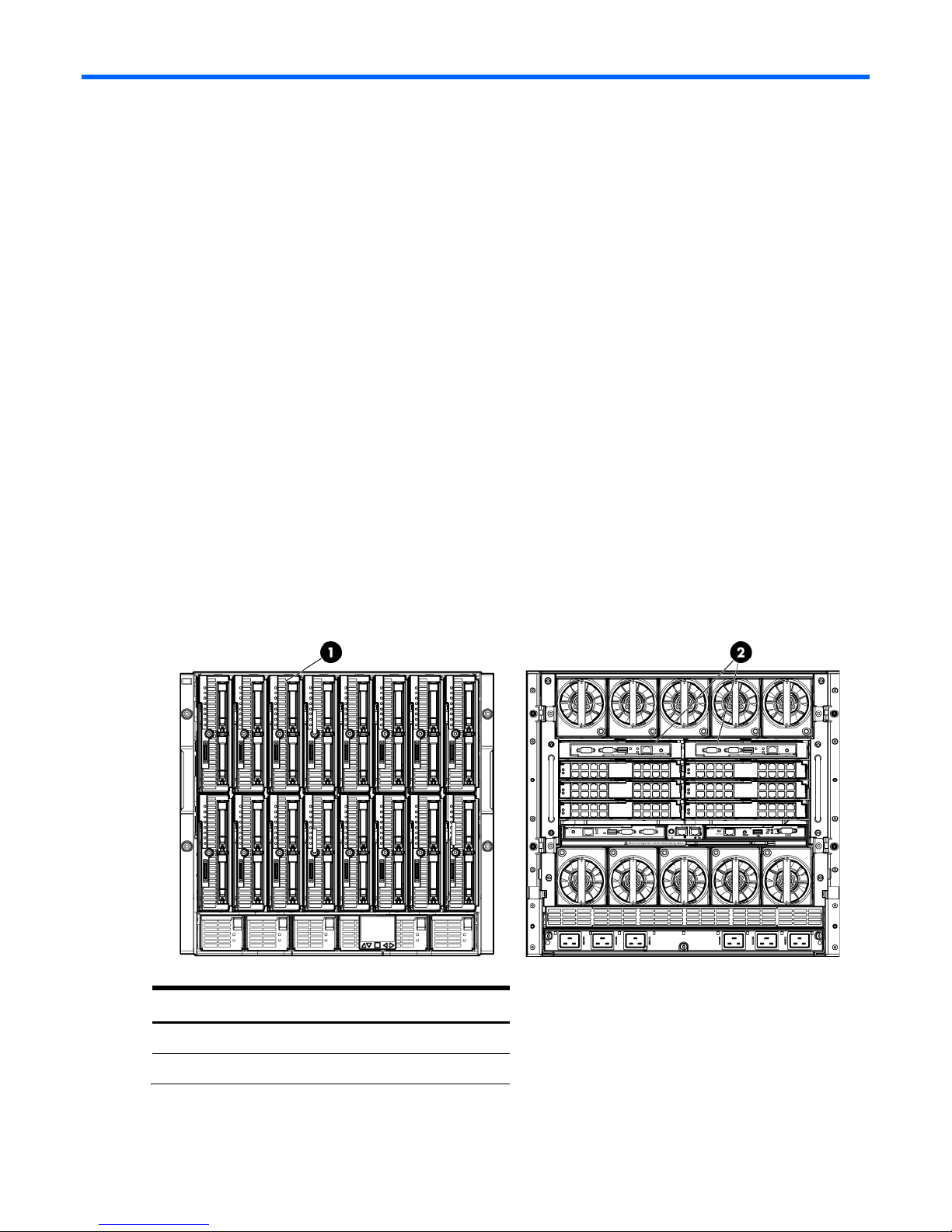
Figure 1-1 c7000 enclosure with four Half Height G6 BladeSystem servers and two Virtual Connect 1:10 Ethernet
modules in Interconnect module bays 1& 2.
Item Description
1 Half Height blades
2 VC Ethernet modules
Chapter 1: Single Domain/Enclosure Scenarios 12
Page 13

Scenario 1:1 – Simple vNet with Active/Standby
Uplinks and Optional Link Aggregation 802.3ad
(LACP) - Windows
Overview
This simple configuration uses the Virtual Connect vNet. The vNet is the simplest way to connect Virtual
Connect to a network and server. In this scenario, the upstream network switch connects a network to a
single port on each VC module.
No special upstream switch configuration is required as the switch is in the factory default configuration,
typically configured as an Access ports.
When configuring Virtual Connect, we can provide several ways to implement network fail-over or
redundancy. One option would be to connect TWO uplinks to a single vNet; those two uplinks would
connect from different Virtual Connect modules within the enclosure and could then connect to the same
upstream switch or two different upstream switches, depending on your redundancy needs. An
alternative would be to configure TWO separate vNets, each with a single uplink configured. Each
option has its advantages and disadvantages. We will review the first option in this scenario.
In addition, several vNets can be configured to support the required networks to the servers within the
BladeSystem enclosure. These networks could be used to separate the various network traffic, such as
iSCSI, backup, VMotion from production network traffic.
Requirements
In order to implement this scenario, an HP BladeSystem c7000 enclosure with one or more server blades
and TWO Virtual Connect Ethernet modules, installed in Bays 1& 2 are required. In addition, we will
require ONE or TWO external Network switches. As Virtual Connect does not appear to the network as
a switch and is transparent to the network, any standard managed switch will work with Virtual Connect.
Scenario 1:1 – Simple vNet with Active/Standby Uplinks and Optional Link Aggregation 802.3ad (LACP) - Windows 13
Page 14
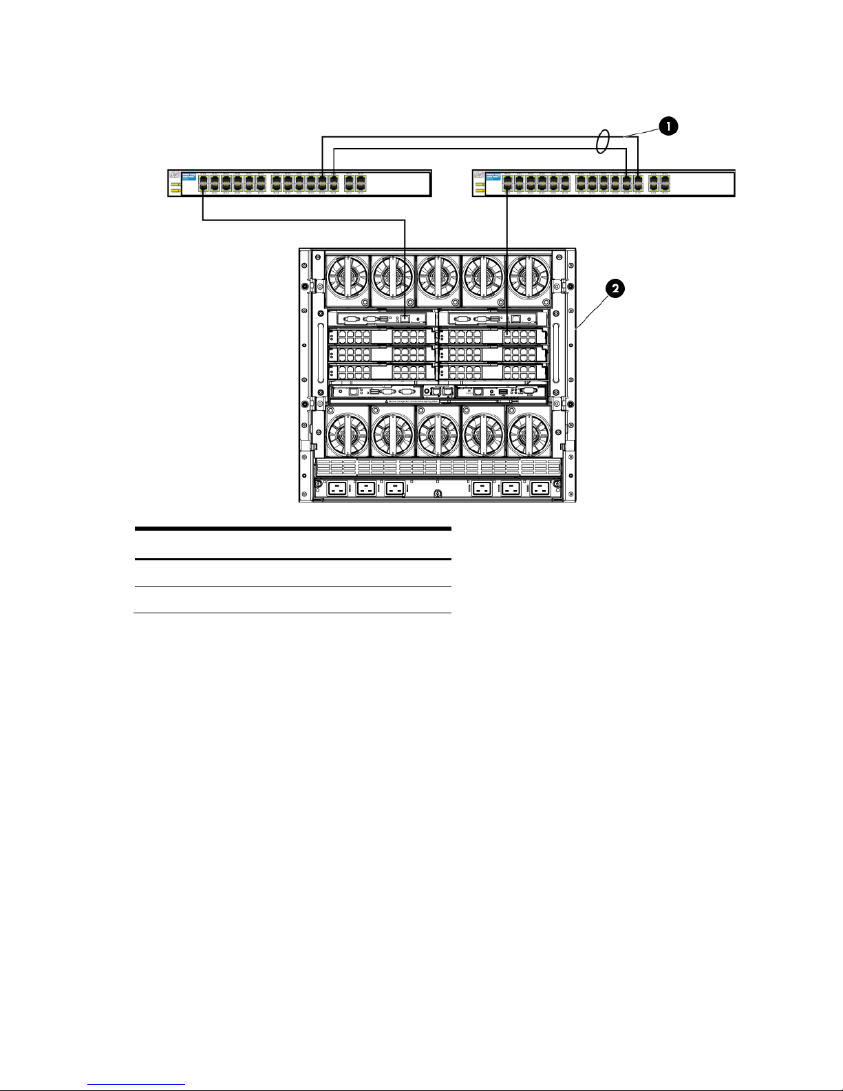
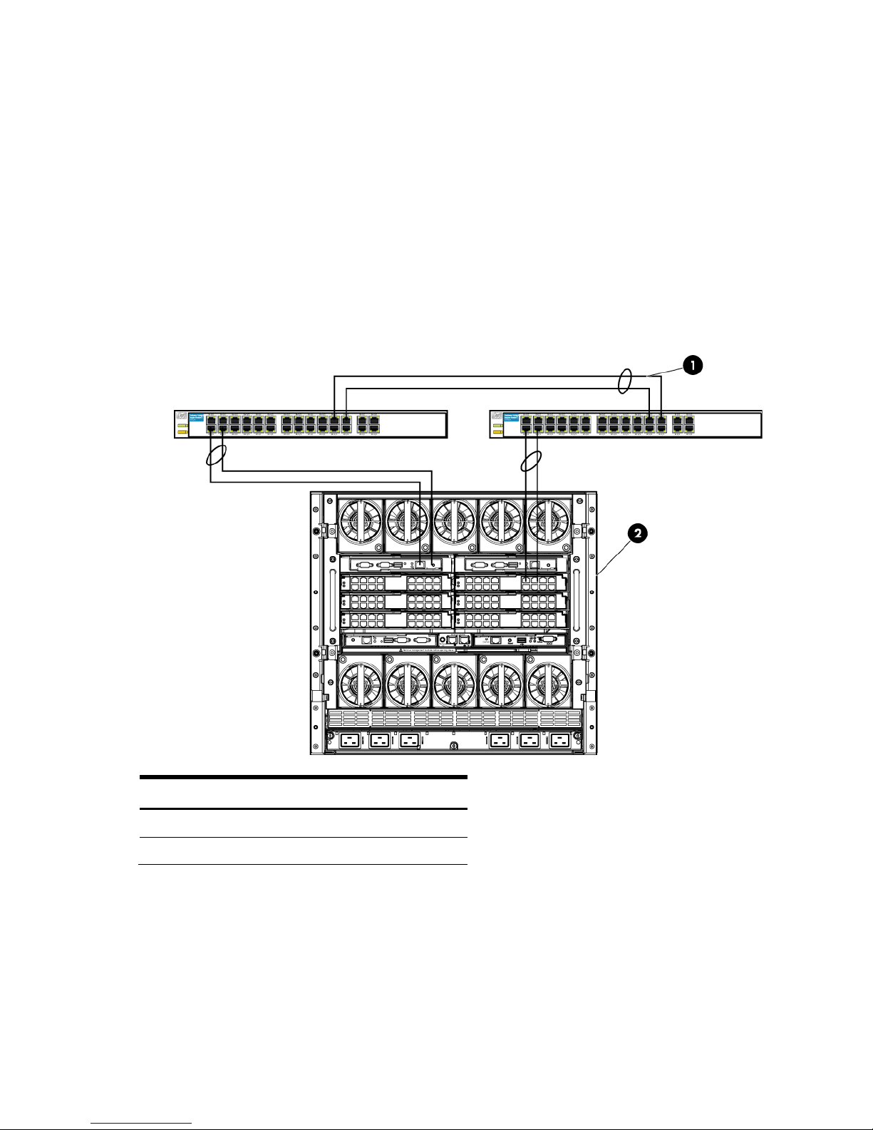
Item
Description
1
Switch Cross Connect
Figure 1-2 Physical View; Shows a single Ethernet uplink from Port 1 on Module 1 to Port 1 on the first network
switch and a single uplink from Port 1 on Module 2 to Port 1 on the second network switch.
2 c7000 Enclosure, rear view
Scenario 1:1 – Simple vNet with Active/Standby Uplinks and Optional Link Aggregation 802.3ad (LACP) - Windows 14
Page 15
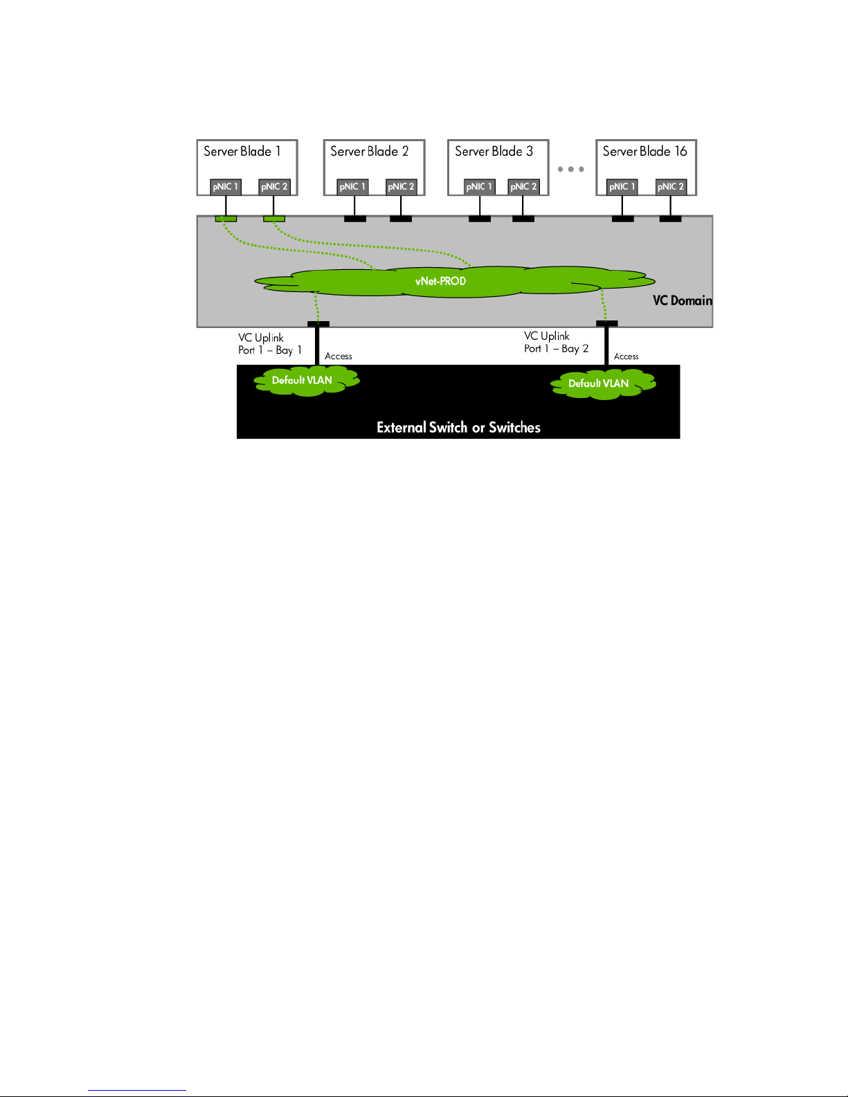
Figure 1-3 Logical View; Shows a single Ethernet uplink from Port 1 on Module 1 on the first network switch and a
single uplink from Port 1 on Module 2 to Port 1 on the second network switch.
Installation and configuration
Switch configuration
Appendices A and B provide a summary of the commands required to configure the switch in either a
Cisco IOS or a ProCurve network infrastructure. The configuration information provided in the appendices
assumes the following information:
• The switch ports are configured as ACCESS ports, either presenting the Default VLAN or a specific
VLAN and will for forwarding untagged frames
• As an alternative, if the switch ports were configured as TRUNK ports and forwarding multiple
VLANS, Virtual Connect would forward those tagged frames to the host NICs configured for this
network. The connected host would then need to be configured to interpret those VLAN tags.
This scenario assumes the switch port is configured as an Access port and the frames are presented to
Virtual Connect as untagged
VC CLI commands
In addition to the GUI many of the configuration settings within VC can be also be accomplished via a CLI
command set. In order to connect to VC via a CLI, open an SSH connection to the IP address of the active
VCM. Once logged in, VC provides a CLI with help menus. Throughout this scenario the CLI commands to
configure VC for each setting will also be provided.
Configuring the VC module
• Physically connect Port 1 of Network switch 1 to Port 1 on the VC module in Bay 1.
Scenario 1:1 – Simple vNet with Active/Standby Uplinks and Optional Link Aggregation 802.3ad (LACP) - Windows 15
Page 16
• Physically connect Port 1 of the second Network switch to Port 1 of the VC module in Bay 2, if you
have only one network switch, connect VC port 1 (Bay 2) to an alternate port on the same switch.
This will NOT create a network loop and does not require Spanning Tree to be configured.
Configuring Fast MAC Cache Failover
• When an uplink on a VC Ethernet Module that was previously in standby mode becomes active, it
can take several minutes for external Ethernet switches to recognize that the c-Class server blades
can now be reached on this newly active connection.
• Enabling Fast MAC Cache Failover forces Virtual Connect to transmit Ethernet packets on newly
active links, which enables the external Ethernet switches to identify the new connection (and update
their MAC caches appropriately). This transmission sequence repeats a few times at the MAC refresh
interval (five seconds is the recommended interval) and completes in about one minute.
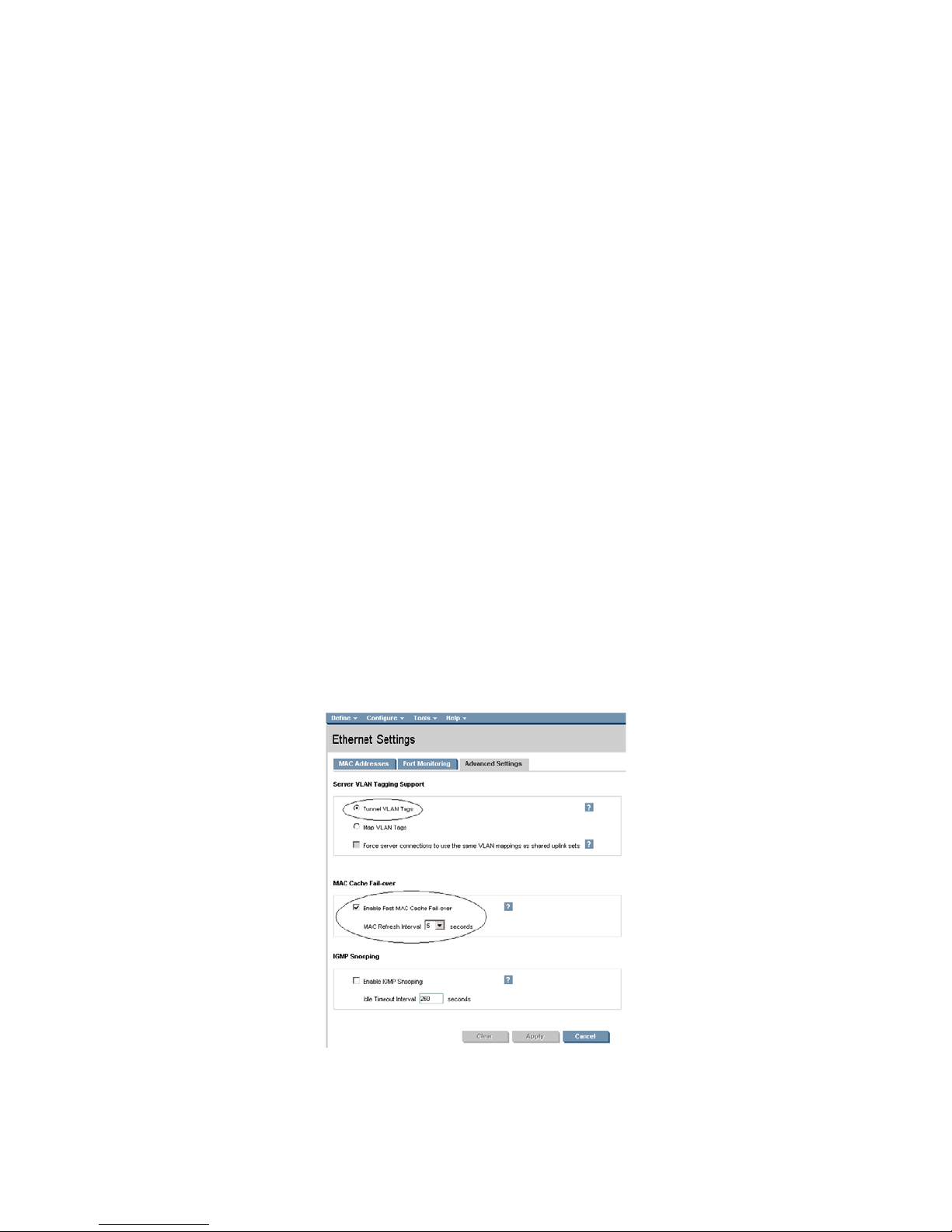
Configuring the VC Module for VLAN Tunneling via GUI (Ethernet settings)
Enable Tunnel VLAN Tags within Virtual Connect
• On the Virtual Connect Manager screen, Left pane, click Ethernet Settings, Advanced Settings
• Select Tunnel VLAN Tags
• Select Fast MAC Cache Fail-over with a refresh of 5
• Select Apply
Configuring the VC Module for VLAN Tunneling via CLI (Ethernet settings)
The following command can be copied and pasted into an SSH based CLI session with Virtual Connect;
• # Set Advanced Ethernet Settings to "Tunnel VLAN Tags" and Enable Fast MAC cache fail-over
• set enet-vlan vlantagcontrol=Tunnel
• set mac-cache Enabled=True Refresh=5
Figure 1-4 Ethernet settings.
Scenario 1:1 – Simple vNet with Active/Standby Uplinks and Optional Link Aggregation 802.3ad (LACP) - Windows 16
Page 17

Defining a new vNet via GUI
Create a vNet and name it “vNet-PROD”
• Login to Virtual Connect, if a Domain has not been created, create it now, but cancel out of the
network and profile wizards.
• On the Virtual Connect Manager screen, click Define, Ethernet Network to create a vNet
• Ether the Network Name of “vNet-PROD”
a. Note; Do NOT select any of the options (ie; Smart Link, Private Networks etc.)
• Select Add Port, then add the following ports;
a. Enclosure 1, Bay 1, Port 1
b. Enclosure 1, Bay 2, Port 1
• Leave Connection Mode as Auto
• Select Apply
Note: By connecting TWO Uplinks from this vNet we have provided a redundant path to the network. As
each uplink originates from a different VC module, one uplink will be Active and the second will be in
Standby. This configuration provides the ability to lose an uplink cable, network switch or depending on
how the NICs are configured at the server (teamed or un-teamed), even a VC module.
Note: Smart Link – In this configuration Smartlink should NOT be enabled. Smartlink is used to turn off
downlink ports within Virtual Connect, if ALL available uplinks to a vNet or SUS are down. We will use
Smartlink in a later scenario.
Defining a new vNet via CLI
The following command(s) can be copied and pasted into an SSH based CLI session with Virtual Connect
# Create the vNet "vNet-PROD" and configure uplinks as discussed above
add Network vNet-PROD
add uplinkport enc0:1:1 Network=vNet-PROD speed=auto
add uplinkport enc0:2:1 Network=vNet-PROD speed=auto
set network vNet-PROD SmartLink=Disabled
Scenario 1:1 – Simple vNet with Active/Standby Uplinks and Optional Link Aggregation 802.3ad (LACP) - Windows 17
Page 18
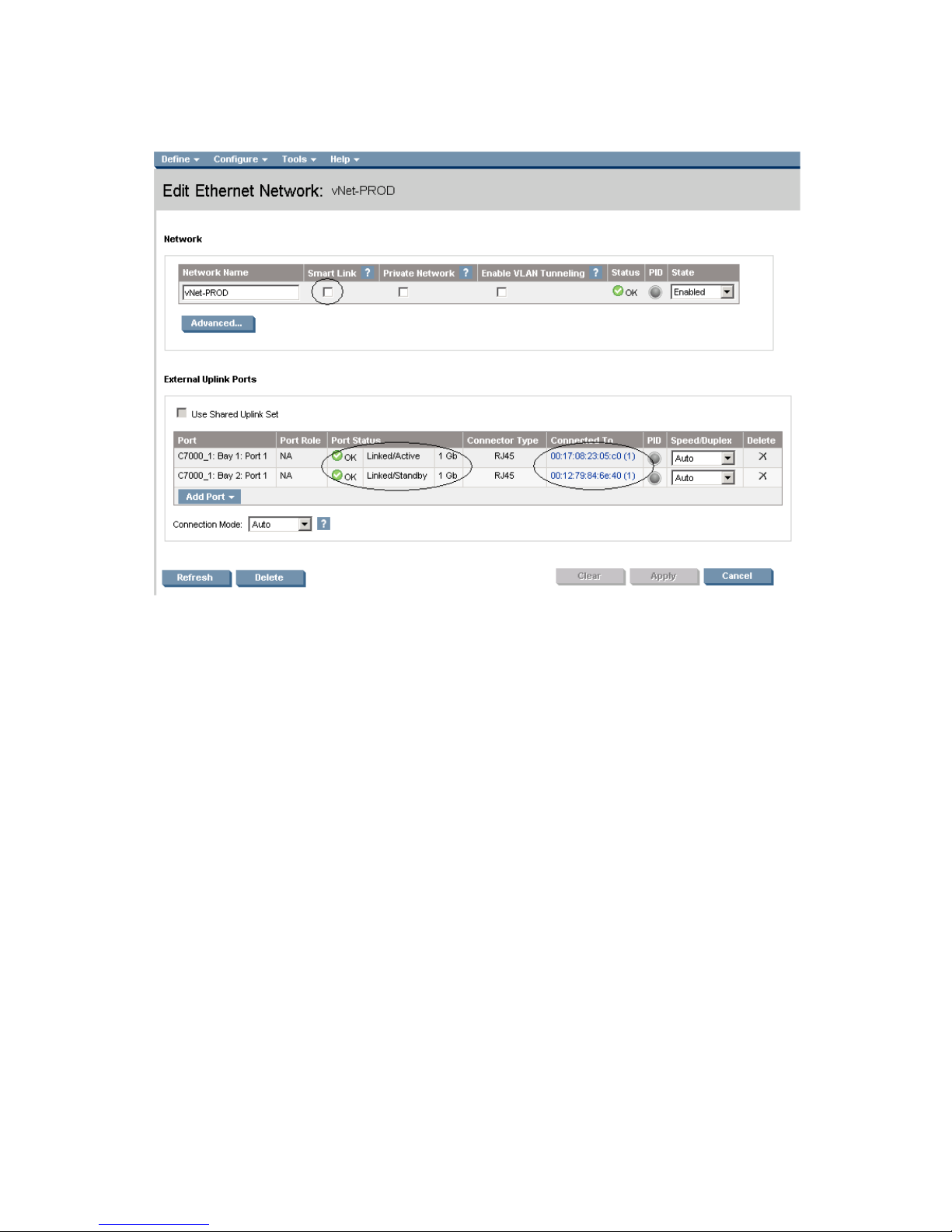
Figure 1-5 Define Ethernet Network (vNet-PROD).
Note: The Port Status and Connected to information. If the connected switch supports LLDP, the connected to
information should be displayed as below
Defining a Server Profile with NIC Connections, via GUI
Each server NIC will connect to a specific network.
On the Virtual Connect Manager screen, click Define, Server Profile to create a Server Profile
• Create a server profile called “App-1”
• In the Network Port 1 drop down box, select “vNet-PROD”
• In the Network Port 2 drop down box, select “vNet-PROD”
• In the Assign the Profile to a Server Bay, select Bay 1 and apply
Defining a Server Profile with NIC Connections, via CLI
The following command(s) can be copied and pasted into an SSH based CLI session with Virtual Connect
# Create and Assign Server Profile App-1 to server bay 1
add profile App-1 –nodefaultenetconn
add enet-connection App-1 pxe=Enabled
add enet-connection App-1 pxe=Disabled
set enet-connection App-1 1 Network=vNet-PROD
set enet-connection App-1 2 Network=vNet-PROD
assign profile App-1 enc0:1
Figure 1-6 Define Server Profile (App- 1)
Scenario 1:1 – Simple vNet with Active/Standby Uplinks and Optional Link Aggregation 802.3ad (LACP) - Windows 18
Page 19
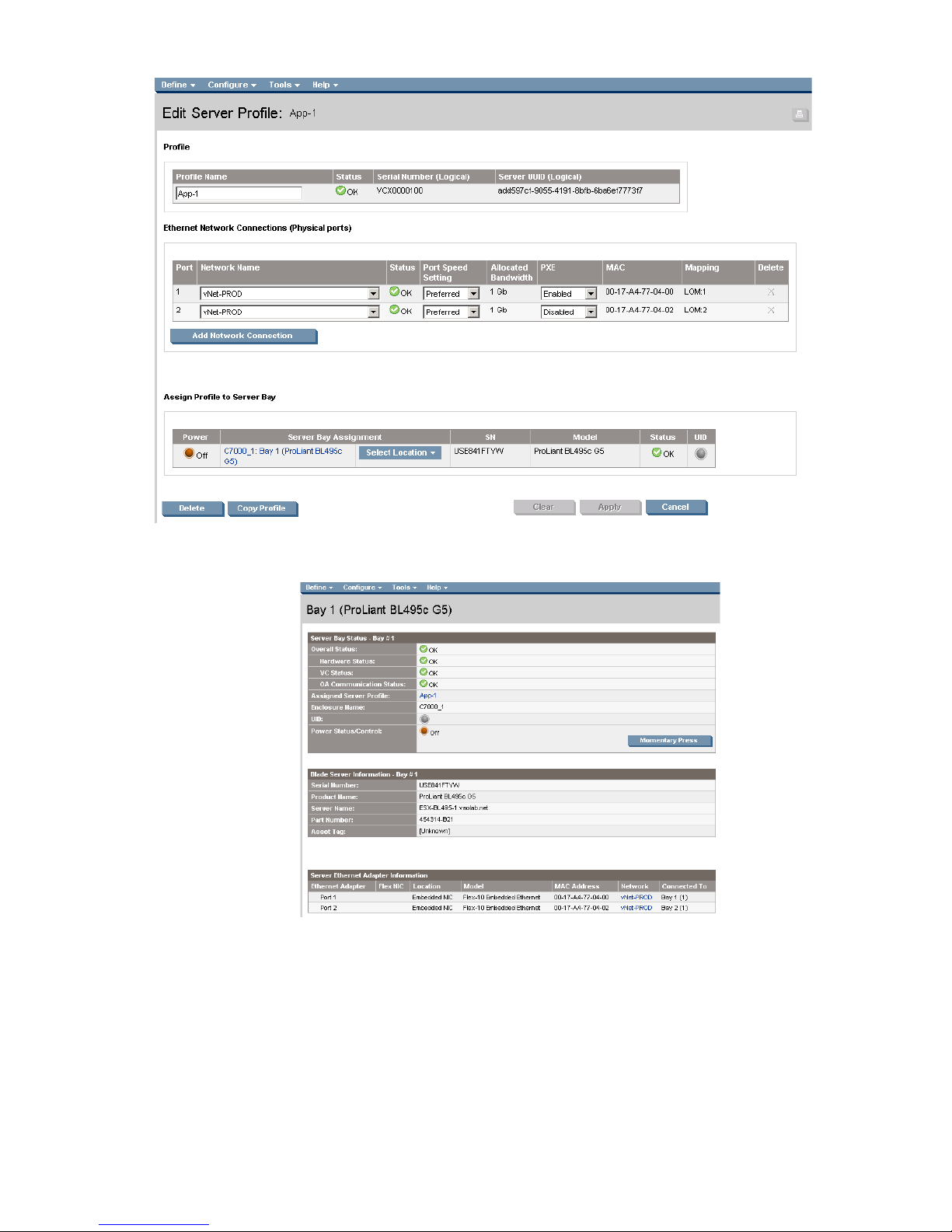
Figure 1-7 Server Profile View Bay 1.
Scenario 1:1 – Simple vNet with Active/Standby Uplinks and Optional Link Aggregation 802.3ad (LACP) - Windows 19
Page 20
Item
Description
1
Switch Cross Connect
Optionally Configuring Additional Uplinks to a vNet (LACP)
If additional uplink bandwidth or redundancy is required, additional uplinks can be configured for an
existing vNet. There are two options available when configuring additional uplinks, when all uplinks
configured within a vNet connect a single VC module to a single upstream switch, ALL links will be active,
providing additional bandwidth, using Link Aggregation Protocol (LACP 802.3ad), this requires the
upstream switch to be configured, on these ports, for link aggregation control protocol (LACP) and be
configured in the same link aggregation group. When some of the uplinks configured within a vNet
connect a VC module to different upstream switches, or from multiple VC modules to a single or multiple
switches, some links will be active and the remaining will be Standby, potentially providing additional
bandwidth as well as increase availability, using Link Aggregation Protocol (LACP 802.3.ad).
Figure 1-8 Shows two Ethernet uplinks from Port 1 and 2 on Module 1 to Port 1 and 2 on the first network switch
and two uplinks from ports 1 and 2 on Module 2 to Ports 1 and 2 on the second network switch.
2 c7000 Enclosure, rear view
Scenario 1:1 – Simple vNet with Active/Standby Uplinks and Optional Link Aggregation 802.3ad (LACP) - Windows 20
Page 21
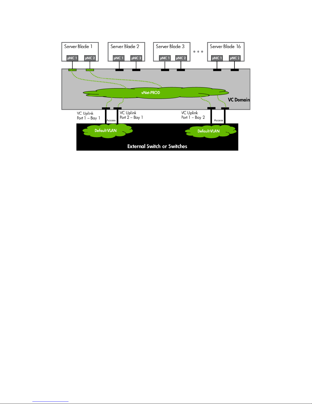
Figure 1-9 Logical View; Shows two Ethernet uplinks from Ports 1& 2 of each VC module to the network switch.
Switch configuration
Appendices A and B provide a summary of the commands required to configure the switch in either a
Cisco IOS or a ProCurve network infrastructure. The configuration information provided in the appendices
assumes the following information:
Note: when adding the additional uplinks, the switch ports connected to Virtual Connect will need to be
configured for LACP and in the same Link Aggregation Group.
Adding uplinks to an existing vNet via GUI
Edit the vNet named “vNet-PROD”
• In the left pane of the Virtual Connect Manager screen, click on the Network “vNet-Prod”
• Select Add Port, then add the following ports;
a. Enclosure 1, Bay 1, Port 2
b. Enclosure 1, Bay 2, Port 2
• Leave Connection Mode as Auto
• Select Apply
Note: By connecting FOUR Uplinks from this vNet we have provided additional bandwidth and a
redundant path to the network as two uplinks will be active and two will be in standby.
Adding uplinks to an existing vNet via CLI
The following command(s) can be copied and pasted into an SSH based CLI session with Virtual Connect
# Edit the vNet "vNet-PROD" and configure uplinks as discussed above
add uplinkport enc0:1:2 Network=vNet-PROD speed=auto
add uplinkport enc0:2:2 Network=vNet-PROD speed=auto
set network vNet-PROD SmartLink=Disabled
Scenario 1:1 – Simple vNet with Active/Standby Uplinks and Optional Link Aggregation 802.3ad (LACP) - Windows 21
Page 22
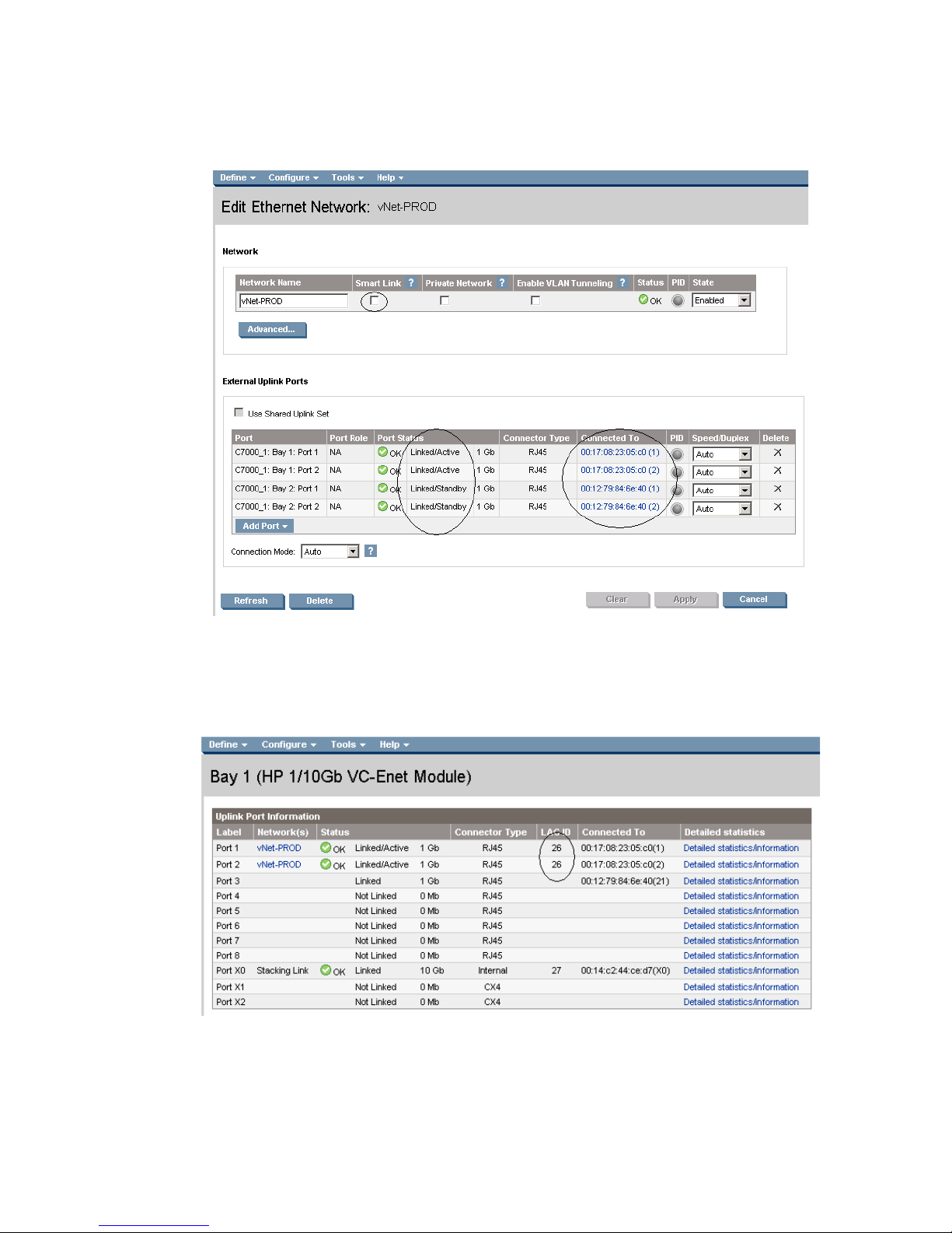
Figure 1-10 Adding uplinks to an existing vNet (vNet-PROD).
Note: The Port Status and Connected to information. If the connected switch supports LLDP, the connected to
information should be displayed as below
Figure 1-11 Link aggregation confirmed – Bay 1.
Note: All connections within an active/active LACP group will have the same LAG ID. To view this, go to the
Interconnect bay and view Uplink Port Information. If you are having trouble establishing an active/active
connection, confirm the LAG ID.
Scenario 1:1 – Simple vNet with Active/Standby Uplinks and Optional Link Aggregation 802.3ad (LACP) - Windows 22
Page 23
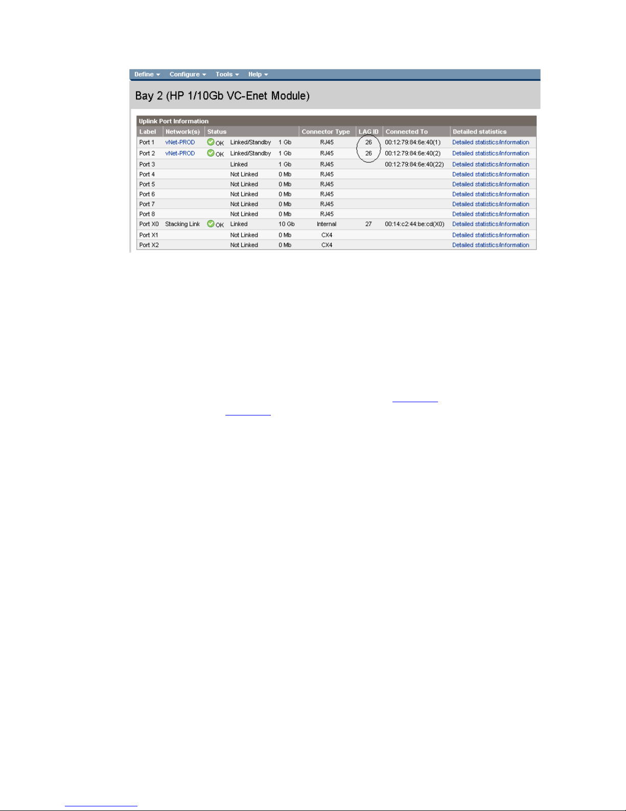
Figure 1-12 Link aggregation confirmed - Bay 2.
Summary
We created a couple different Virtual Connect Network solutions; base initially for availability, one link
was active while the second was in standby mode. We later added two additional links; this increased
the network bandwidth to the Virtual Connect network, while still maintaining availability.
When VC profile App-1 is applied to the server in bay1 and is powered up, it has one NIC through each
module connected to “vNet-PROD”, which connects to the network infrastructure through a pair of 1Gb
uplinks. These NICs could now be configured as individual NICs (Figure 1-8
as a pair of TEAMED NICs (Figure 1-9
the network through either NIC or either uplink cable, depending on which is active at the time.
When additional bandwidth was required, additional uplinks were added to the existing vNet, this
process had no effect on the server profile.
As additional servers are added to the enclosure, simply create additional profiles, or copy existing
profiles, configure the NICs for vNet-PROD and apply them to the appropriate server bays.
Results
The following graphic provides an example of a Windows 2003 server with TWO NICs connected to the
network, each NIC has its own TCP/IP address, either or both NICs could be actively working on the
network.
) with their own IP address or
). Either NIC could be active. As a result, this server could access
Scenario 1:1 – Simple vNet with Active/Standby Uplinks and Optional Link Aggregation 802.3ad (LACP) - Windows 23
Page 24
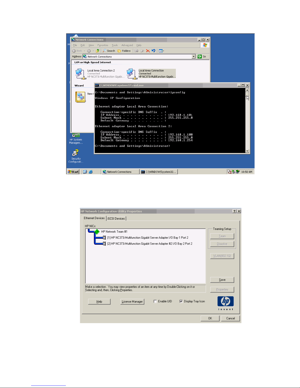
Figure 1-13 Both NICs for Profile App-1are connected to the network through vNet-PROD.
The following graphics provide an example of a Windows 2003 server with TWO NICs teamed and
connected to the network. One NIC will be active while the other is in standby. In the event of an Uplink
or switch failure, VC will fail-over to the standby uplinks.
Figure 1-14 Both NICs, using the HP Network Configuration Utility.
Scenario 1:1 – Simple vNet with Active/Standby Uplinks and Optional Link Aggregation 802.3ad (LACP) - Windows 24
Page 25
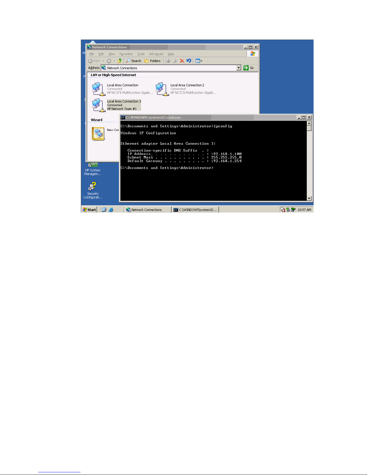
Figure 1-15 Both NICs for Profile App-1are teamed and connected to the network through vNet-PROD.
Scenario 1:1 – Simple vNet with Active/Standby Uplinks and Optional Link Aggregation 802.3ad (LACP) - Windows 25
Page 26

Scenario 1:2 – Multiple Simple Networks with
Active\Active Uplinks and Optional Link
Aggregation 802.3ad (LACP) - Windows
Overview
This simple configuration uses the Virtual Connect vNet. The vNet is the simplest way to connect Virtual
Connect to a network and server. In this scenario, the upstream network switch connects a network to a
single port on each VC module.
No special upstream switch configuration is required as the switch is in the factory default configuration.
As discussed in scenario 1:1, when configuring Virtual Connect, we can provide several ways to
implement network fail-over or redundancy. In this scenario we will configure TWO separate vNets, each
with a single uplink configured from each VC module. We will later connect additional uplinks, to
provide additional bandwidth.
In addition, several vNets can be configured to support the required networks to the servers within the
BladeSystem enclosure. These networks could be used to separate the various network traffic, such as
iSCSI, backup, VMotion from production network traffic.
Requirements
In order to implement this scenario, an HP BladeSystem c7000 enclosure with one or more server blades
and TWO Virtual Connect Ethernet modules, installed in Bays 1& 2 are required. In addition, we will
require ONE or TWO external Network switches. As Virtual Connect does not appear to the network as
a switch and is transparent to the network, any standard managed switch will work with Virtual Connect.
Scenario 1:2 – Multiple Simple Networks with Active\Active Uplinks and Optional Link Aggregation 802.3ad (LACP) - Windows
26
Page 27

Figure 1-16 Physical View; Shows a single Ethernet uplink from Port 1 on Module 1 to Port 1 on the first network switch and a
single uplink from Port 1 on Module 2 to Port 1 on the second network switch.
Item Description
1 Switch Cross Connect
2 c7000 Enclosure, rear view
Scenario 1:2 – Multiple Simple Networks with Active\Active Uplinks and Optional Link Aggregation 802.3ad (LACP) - Windows
27
Page 28
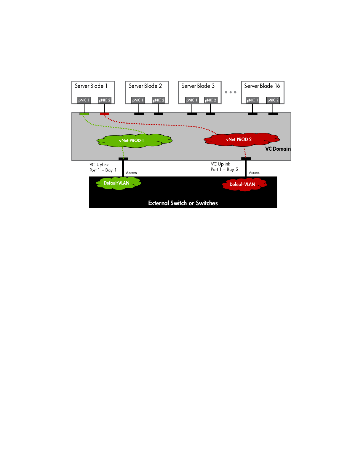
Figure 1-17 Logical View; Shows a single Ethernet uplink from Port 1 on Module 1 to Port 1 on the first network switch and a
single uplink from Port 1 on Module 2 to Port 1 on the second network switch. The Uplink from Module 1 is associated with
vNet-PROD-1 and the Uplink from Module 2 is associated with vNet-PROD-2. Both of these connections, in this example, connect
to the same network.
Installation and configuration
Switch configuration
Appendices A and B provide a summary of the commands required to configure the switch in either a
Cisco IOS or a ProCurve network infrastructure. The configuration information provided in the appendices
assumes the following information:
• The switch ports are configured as ACCESS ports, either presenting the Default VLAN or a specific
VLAN and will for forwarding untagged frames
• As an alternative, if the switch ports were configured as TRUNK ports and forwarding multiple
VLANS, Virtual Connect would forward those tagged frames to the host NICs configured for this
network. The connected host would then need to be configured to interpret those VLAN tags.
This scenario assumes the switch port is configured as an Access port and the frames are presented to
Virtual Connect as untagged
VC CLI commands
In addition to the GUI many of the configuration settings within VC can be also be accomplished via a CLI
command set. In order to connect to VC via a CLI, open an SSH connection to the IP address of the active
VCM. Once logged in, VC provides a CLI with help menus. Throughout this scenario the CLI commands to
configure VC for each setting will also be provided.
Configuring the VC module
• Physically connect port 1 of the Network switch to port 1 on the VC module in Bay 1.
Scenario 1:2 – Multiple Simple Networks with Active\Active Uplinks and Optional Link Aggregation 802.3ad (LACP) - Windows
28
Page 29
• Connect Port 1 of the second Network switch to Port 1 of the VC module in Bay 2, if you have only
one network switch, connect the second VC module, port 1 to an alternate port on the same switch.
This will NOT create a network loop and does not require Spanning Tree to be configured.
Configuring Fast MAC Cache Failover
• When an uplink on a VC Ethernet Module that was previously in standby mode becomes active, it
can take several minutes for external Ethernet switches to recognize that the c-Class server blades
can now be reached on this newly active connection.
• Enabling Fast MAC Cache Failover forces Virtual Connect to transmit Ethernet packets on newly
active links, which enables the external Ethernet switches to identify the new connection (and update
their MAC caches appropriately). This transmission sequence repeats a few times at the MAC refresh
interval (five seconds is the recommended interval) and completes in about one minute.
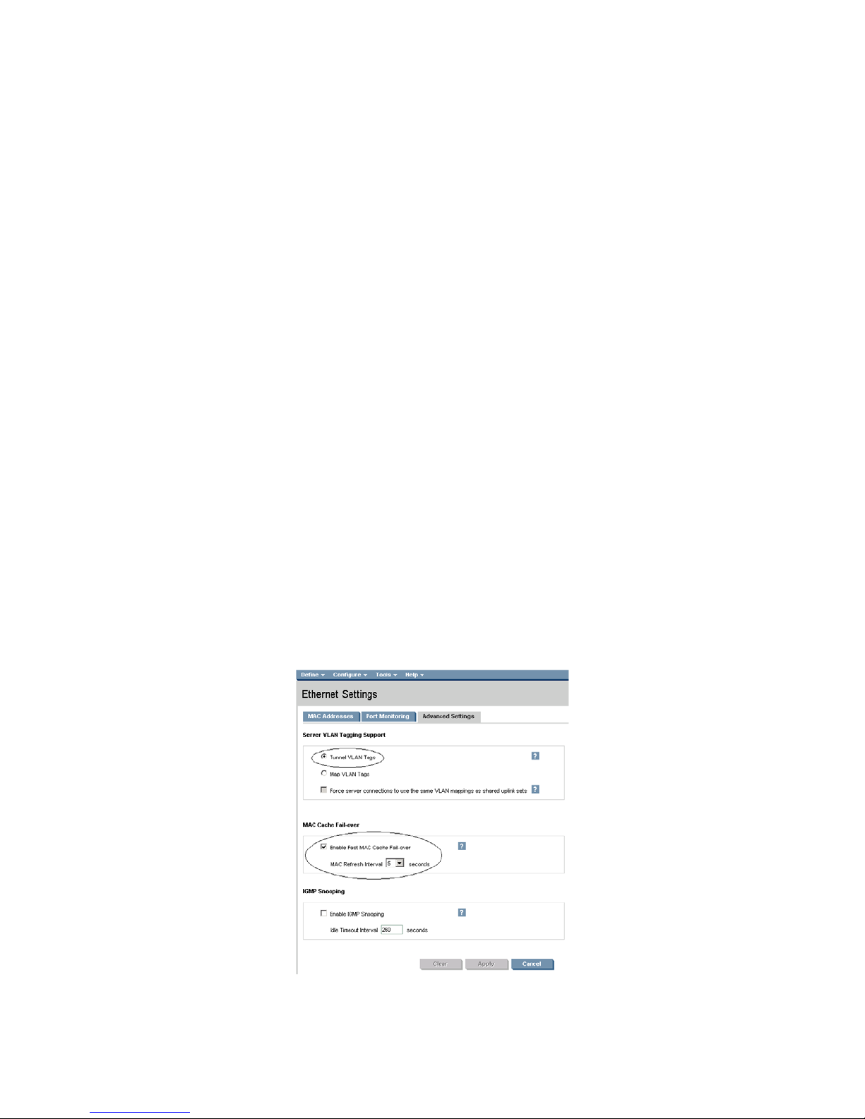
Configuring the VC Module for VLAN Tunneling via GUI (Ethernet settings)
Enable Tunnel VLAN Tags within Virtual Connect
• On the Virtual Connect Manager screen, Left pane, click Ethernet Settings, Advanced Settings
• Select Tunnel VLAN Tags
• Select Fast MAC Cache Fail-over with a refresh of 5
• Select Apply
Configuring the VC Module VLAN Tunneling via CLI (Ethernet settings)
The following command can be copied and pasted into an SSH based CLI session with Virtual Connect
# Set Advanced Ethernet Settings to "Tunnel VLAN Tags" and Enable Fast MAC cache fail-over
set enet-vlan vlantagcontrol=Tunnel
set mac-cache Enabled=True Refresh=5
Figure 1-18 Ethernet Settings.
Scenario 1:2 – Multiple Simple Networks with Active\Active Uplinks and Optional Link Aggregation 802.3ad (LACP) - Windows
29
Page 30

Defining two new vNet via GUI
Create a vNet and name it “vNet-PROD-1”
• On the Virtual Connect Manager screen, click Define, Ethernet Network to create a vNet
• Ether the Network Name of “vNet-PROD-1”
a. Optionally select Smart Link, but, do NOT select any of the other options (ie; Private
Networks etc.)
• Select Add Port, then add the following ports;
a. Enclosure 1, Bay 1, Port 1
• Leave Connection Mode as Auto
• Select Apply
Create a vNet and name it “vNet-PROD-2”
• On the Virtual Connect Manager screen, click Define, Ethernet Network to create a vNet
• Ether the Network Name of “vNet-PROD-2”
a. Select Smart Link, but, do NOT select any of the other options (ie; Private Networks etc.)
• Select Add Port, then add the following ports;
a. Enclosure 1, Bay 2, Port 1
• Leave Connection Mode as Auto
• Select Apply
Note: By creating TWO vNets we have provided a redundant path to the network. As each uplink
originates from a different VC module and vNet both, uplinks will be active. This configuration provides
the ability to lose an uplink cable, network switch or depending on how the NICs are configured at the
server (teamed or un-teamed), even a VC module.
Note: Smart Link – In this configuration Smartlink SHOULD be enabled. Smartlink is used to turn off
downlink ports within Virtual Connect if ALL available uplinks to a vNet or SUS are down. In this scenario
if an upstream switch or all cables to a vNet were to fail on a specific vNet, VC would turn off the
downlink ports connect to that vNet, which would then force the NIC Teaming software to fail-over to the
alternate NIC.
Defining a new vNet via CLI
The following command(s) can be copied and pasted into an SSH based CLI session with Virtual Connect
# Create the vNet "vNet-PROD" and configure uplinks as discussed above
add Network vNet-PROD-1
add uplinkport enc0:1:1 Network=vNet-PROD-1 speed=auto
set network vNet-PROD-1 SmartLink=Enabled
add Network vNet-PROD-2
add uplinkport enc0:2:1 Network=vNet-PROD-2 speed=auto
set network vNet-PROD-2 SmartLink=Enabled
Scenario 1:2 – Multiple Simple Networks with Active\Active Uplinks and Optional Link Aggregation 802.3ad (LACP) - Windows
30
Page 31

Figure 1-19 Define Ethernet Network (vNet-PROD-1).
Note: The Port Status and Connected to information. If the connected switch supports LLDP, the connected to
information should be displayed as below.
Figure 1-20 Define Ethernet Network (vNet-PROD-2).
Note: The Port Status and Connected to information. If the connected switch supports LLDP, the connected to
information should be displayed as below
Scenario 1:2 – Multiple Simple Networks with Active\Active Uplinks and Optional Link Aggregation 802.3ad (LACP) - Windows
31
Page 32

Item
Description
Optionally Configuring Additional Uplinks to a vNet (LACP)
If additional uplink bandwidth or redundancy is required, additional uplinks can be configured for an
existing vNet. There are two options available when configuring additional uplinks, when all uplinks
configured within a vNet connect a single VC module to a single upstream switch, ALL links will be active,
providing additional bandwidth, using Link Aggregation Protocol (LACP 802.3ad), this requires the
upstream switch to be configured, on these ports, for link aggregation control protocol (LACP) and be
configured in the same link aggregation group. When some of the uplinks configured within a vNet
connect a VC module to different upstream switches, or from multiple VC modules to a single or multiple
switches, some links will be active and the remaining will be Standby, potentially providing additional
bandwidth as well as increase availability, using Link Aggregation Protocol (LACP 802.3.ad).
Figure 1-21 Physical View; Shows two Ethernet uplinks from Ports 1 & 2 on Module 1 to Ports 1 & 2 on the first
network switch and two uplinks from Ports 1 and 2 on Module 2 to Ports 1 & 2 on the second network switch.
1 Switch Cross Connect
2 c7000 Enclosure, rear view
Scenario 1:2 – Multiple Simple Networks with Active\Active Uplinks and Optional Link Aggregation 802.3ad (LACP) - Windows
32
Page 33

Figure 1-22 Logical View; Shows two Ethernet uplinks from Ports 1&2 of each VC module to the network switch.
Switch configuration
Appendices A and B provide a summary of the commands required to configure the switch in either a
Cisco IOS or a ProCurve network infrastructure. The configuration information provided in the appendices
assumes the following information:
• The switch ports are configured as ACCESS ports, either presenting the Default VLAN or a specific
VLAN and will for forwarding untagged frames
• As an alternative, if the switch ports were configured as TRUNK ports and forwarding multiple
VLANS, Virtual Connect would forward those tagged frames to the host NICs configured for this
network. The connected host would then need to be configured to interpret those VLAN tags.
• When adding the additional uplinks to the vNet, the switch ports connected to Virtual Connect will
need to be configured for LACP and configured for the same Link Aggregation Group.
Adding uplinks to an existing vNet via GUI
Edit the vNet named “vNet-PROD-1”
• In the left pane of the Virtual Connect Manager screen, click on the vNet
• Select Add Port, then add the following ports;
a. Enclosure 1, Bay 1, Port 2
• Leave Connection Mode as Auto
• Select Apply
• Edit the vNet named “vNet-PROD-2”
• In the left pane of the Virtual Connect Manager screen, click on the vNet
• Select Add Port, then add the following ports;
a. Enclosure 1, Bay 2, Port 1
• Leave Connection Mode as Auto
• Select Apply
Scenario 1:2 – Multiple Simple Networks with Active\Active Uplinks and Optional Link Aggregation 802.3ad (LACP) - Windows
33
Page 34

Note: By connecting two Uplinks from each vNet we have provided additional bandwidth and redundant
paths to the network.
Adding uplinks to an existing vNet via CLI
The following command(s) can be copied and pasted into an SSH based CLI session with Virtual Connect
# Edit the vNet "vNet-PROD-1" and configure uplinks as discussed above
add uplinkport enc0:1:2 Network=vNet-PROD-1 speed=auto
# Edit the vNet "vNet-PROD-2" and configure uplinks as discussed above
add uplinkport enc0:2:2 Network=vNet-PROD-2 speed=auto
Figure 1-23 Adding uplinks to an existing vNet (vNet-PROD-1).
Note: The Port Status and Connected to information. If the connected switch supports LLDP, the connected to
information should be displayed as below
Scenario 1:2 – Multiple Simple Networks with Active\Active Uplinks and Optional Link Aggregation 802.3ad (LACP) - Windows
34
Page 35

Figure 1-24 Adding uplinks to an existing vNet (vNet-PROD-2).
Note: The Port Status and Connected to information. If the connected switch supports LLDP, the connected to
information should be displayed as below
Figure 1-25 Link aggregation confirmed – Bay 1.
Note: All connections within an active/active LACP group will have the same LAG ID. To view this, go to the
Interconnect bay and view Uplink Port Information. If you are having troubles establishing an active/active
connection, confirm the LAG ID.
Scenario 1:2 – Multiple Simple Networks with Active\Active Uplinks and Optional Link Aggregation 802.3ad (LACP) - Windows
35
Page 36

Figure 1-26 Link aggregation confirmed - Bay 2.
Defining a Server Profile with NIC Connections, via GUI
Each server NIC will connect to a specific network.
On the Virtual Connect Manager screen, click Define, Server Profile to create a Server Profile
• Create a server profile called “App-1”
• In the Network Port 1 drop down box, select “vNet-PROD-1”
• In the Network Port 2 drop down box, select “vNet-PROD-2”
• In the Assign the Profile to a Server Bays, select Bay 1 and apply
Defining a Server Profile with NIC Connections, via CLI
The following command(s) can be copied and pasted into an SSH based CLI session with Virtual Connect
# Create and Assign Server Profile App-1
add profile App-1 –nodefaultenetconn
add enet-connection App-1 pxe=Enabled
add enet-connection App-1 pxe=Disabled
set enet-connection App-1 1 Network=vNet-PROD-1
set enet-connection App-1 2 Network=vNet-PROD-2
assign profile App-1 enc0:1
Scenario 1:2 – Multiple Simple Networks with Active\Active Uplinks and Optional Link Aggregation 802.3ad (LACP) - Windows
36
Page 37

Figure 1-27 Define Server Profile (App-1).
Figure 1-28 View Bay 1.
Scenario 1:2 – Multiple Simple Networks with Active\Active Uplinks and Optional Link Aggregation 802.3ad (LACP) - Windows
37
Page 38

Summary
We created a couple different Virtual Connect Network solutions; base initially for bandwidth, which also
provided additional availability. Two VC networks were created, both with a single active uplink. We
later added two additional links; this increased the network bandwidth to the Virtual Connect networks,
while still maintaining availability.
When VC profile App-1 is applied to the server in bay1 and is powered up, it has two NICs connected to
“vNet-PROD-1” and “vNet-PROD-2”, which connects to the network infrastructure through a two 1Gb
uplinks. These NICs could now be configured as individual NICs with their own IP address or as a pair of
TEAMED NICs. Either NIC could be active. As a result, this server could access the network through
either NIC or either uplink cable, depending on which NIC is active at the time.
When additional bandwidth was required, additional uplinks were added to each vNet.
As additional servers are added to the enclosure, simply create additional profiles, configure the NICs for
vNet-PROD-1 and vNet-PROD-2 and apply them to the appropriate server bays.
Results
The following graphic provides an example of a Windows 2003 server with TWO NICs connected to the
network, each NIC has its own TCP/IP address, either or both NICs could be actively working on the
network.
Figure 1-29 Both NICs for Profile App-1are connected to the network through vNet-PROD-1 or vNet-PROD-2.
Scenario 1:2 – Multiple Simple Networks with Active\Active Uplinks and Optional Link Aggregation 802.3ad (LACP) - Windows
38
Page 39

The following graphics provide an example of a Windows 2003 server with TWO NICs teamed and
connected to the network. One NIC will be active, the other NIC will be in standby, in the event of an
Uplink, switch or VC module failure; the teaming software will fail the NIC over to the alternate path, as
required.
Figure 1-30 Team both NICs, using the HP Network Configuration Utility.
Figure 1-31 Both NICs for Profile App-1are teamed and could connect connected to the network through either
vNet-PROD-1 or vNet-PROD-2, depending on which NIC is active.
Scenario 1:2 – Multiple Simple Networks with Active\Active Uplinks and Optional Link Aggregation 802.3ad (LACP) - Windows
39
Page 40

Scenario 1:3 – Multiple Simple Networks
Providing Redundancy and Link Aggregation
802.3ad (LACP) with VLAN Tunneling –
VMware ESX
Overview
This configuration uses the Virtual Connect vNet. The vNet is the simplest way to connect Virtual Connect
to a network and server. In this scenario, the upstream network switch is configured to pass multiple
VLANs to two ports on each VC module.
The upstream switch ports will be configured as “trunk” ports for several VLANs, VLAN 101 will be
configured as untagged as this VLAN will be used for console or management access.
Requirements
In order to implement this scenario, an HP BladeSystem c7000 enclosure with one of more server blades
and TWO Virtual Connect Ethernet modules, installed in Bays 1& 2 are required. In addition, we will
require ONE or TWO external Network switches. As Virtual Connect does not appear to the network as
a switch and is transparent to the network, any standard managed switch will work with Virtual Connect.
Configuring Uplinks to a vNet (LACP)
When all uplinks configured within a vNet connect a VC module to an upstream switch, ALL links could
be active, providing additional bandwidth, using Link Aggregation Protocol (LACP 802.3ad), this requires
the upstream switch to be configured, on these ports, for link aggregation control protocol (LACP).
When some of the uplinks configured within a vNet connect a VC module to different upstream switches,
some links will be active and the remaining will be Standby, providing additional bandwidth and/or
availability, using Link Aggregation Protocol (LACP 802.3.ad).
Scenario 1:3 – Multiple Simple Networks Providing Redundancy and Link Aggregation 802.3ad (LACP) with VLAN Tunneling –
VMware ESX 40
Page 41

Item
Description
1
Switch Cross Connect
Figure 1-32 Physical View; Shows two Ethernet uplinks from Ports 1 & 2 on Module 1 to Ports 1 & 2 on the first
network switch and two uplinks from Ports 1 and 2 on Module 2 to Ports 1 & 2 on the second network switch.
2 c7000 Enclosure, rear view
Scenario 1:3 – Multiple Simple Networks Providing Redundancy and Link Aggregation 802.3ad (LACP) with VLAN Tunneling –
VMware ESX 41
Page 42

Figure 1-33 Logical View; Shows two Ethernet uplinks from Ports 1&2 of each VC module to the network switch.
Installation and configuration
Switch configuration
Appendices A and B provide a summary of the commands required to configure the switch in either a
Cisco IOS or a ProCurve network infrastructure. The configuration information provided in the appendices
assumes the following information:
• The upstream switch ports are configured as TRUNK ports, presenting VLANs 101-104 (VLAN 101
is set to default (untagged)).
• The upstream switch ports are configured within the same Link Aggregation Group
• When adding the additional uplinks to the vNet, the switch ports connected to Virtual Connect will
need to be configured for LACP and configured for the same Link Aggregation Group.
VC CLI commands
Many of the configuration settings within VC can be also be accomplished via a CLI command set. In order
to connect to VC via a CLI, open an SSH connection to the IP address of the active VCM. Once logged in,
VC provides a CLI with help menus. Through this scenario the CLI commands to configure VC for each
setting will also be provided.
Configuring the VC module
• Physically connect Ports 1 and 2 of the first network switch to Ports 1 and 2 on the VC module in Bay
1.
• Physically connect Ports 1 and 2 of the second network switch to Ports 1 and 2 of the VC module in
Bay 2, if you have only one network switch, connect the second VC module cables to alternates port
on the same switch. This will NOT create a network loop and does not require Spanning Tree to be
configured.
Scenario 1:3 – Multiple Simple Networks Providing Redundancy and Link Aggregation 802.3ad (LACP) with VLAN Tunneling –
VMware ESX 42
Page 43

Configuring Fast MAC Cache Failover
• When an uplink on a VC Ethernet Module that was previously in standby mode becomes active, it
can take several minutes for external Ethernet switches to recognize that the c-Class server blades
can now be reached on this newly active connection.
• Enabling Fast MAC Cache Failover forces Virtual Connect to transmit Ethernet packets on newly
active links, which enables the external Ethernet switches to identify the new connection (and update
their MAC caches appropriately). This transmission sequence repeats a few times at the MAC refresh
interval (five seconds is the recommended interval) and completes in about one minute.
Note: Fast MAC Cache Fail-over is less critical with this scenario, as no uplinks are configured in
standby mode, all uplinks are active.
Configuring the VC Module for VLAN Tunneling via GUI (Ethernet settings)
Enable Tunnel VLAN Tags within Virtual Connect
• On the Virtual Connect Manager screen, Left pane, click Ethernet Settings, Advanced Settings
• Select Tunnel VLAN Tags
• Select Fast MAC Cache Fail-over with a refresh of 5
• Select Apply
Configuring the VC Module for VLAN Tunneling via CLI (Ethernet settings)
The following command can be copied and pasted into an SSH based CLI session with Virtual Connect;
# Set Advanced Ethernet Settings to "Tunnel VLAN Tags" and Enable Fast MAC cache fail-over
set enet-vlan vlantagcontrol=Tunnel
set mac-cache Enabled=True Refresh=5
Figure 1-34 Ethernet Settings.
Scenario 1:3 – Multiple Simple Networks Providing Redundancy and Link Aggregation 802.3ad (LACP) with VLAN Tunneling –
VMware ESX 43
Page 44

Defining two new vNets via GUI
1. Create a vNet and name it “vNet-PROD-1”
• On the Virtual Connect Manager screen, click Define, Ethernet Network to create a vNet
• Ether the Network Name of “vNet-PROD-1”
a. Select Enable VLAN Tunneling
b. Optionally select Smart Link, but, do NOT select Private Networks
• Select Add Port, then add the following ports;
a. Enclosure 1, Bay 1, Ports1 & 2
• Leave Connection Mode as Auto
• Select Apply
2. Create a vNet and name it “vNet-PROD-2”
• On the Virtual Connect Manager screen, click Define, Ethernet Network to create a vNet
• Ether the Network Name of “vNet-PROD-2”
a. Select Enable VLAN Tunneling
b. Optionally select Smart Link, but, do NOT select Private Networks
• Select Add Port, then add the following ports;
a. Enclosure 1, Bay 2, Ports 1 & 2
• Leave Connection Mode as Auto
• Select Apply
Note: By creating TWO vNets we have provided a redundant path to the network. As each uplink pair
originates from a different VC module within each vNet, both uplinks pairs will be active. This
configuration provides the ability to lose an uplink cable/pair, network switch or depending on how the
NICs are configured at the server (teamed or un-teamed), even a VC module.
Note: Smart Link – In this configuration Smartlink SHOULD be enabled. Smartlink is used to turn off
downlink ports within Virtual Connect if ALL available uplinks to a vNet or SUS are down. In this scenario
if an upstream switch or all cables to a vNet were to fail, VC would turn off the downlink ports connect to
that vNet, which would then force the NIC Teaming software to fail-over to the alternate NIC.
Defining a new vNet via CLI
The following command(s) can be copied and pasted into an SSH based CLI session with Virtual Connect
# Create the vNet "vNet-PROD" and configure uplinks as discussed above
add Network vNet-PROD-1
add uplinkport enc0:1:1 Network=vNet-PROD-1 speed=auto
add uplinkport enc0:1:2 Network=vNet-PROD-1 speed=auto
set network vNet-PROD-1 SmartLink=Enabled VLanTunnel=Enabled
add Network vNet-PROD-2
add uplinkport enc0:2:1 Network=vNet-PROD-2 speed=auto
add uplinkport enc0:2:2 Network=vNet-PROD-2 speed=auto
set network vNet-PROD-2 SmartLink=Enabled VLanTunnel=Enabled
Scenario 1:3 – Multiple Simple Networks Providing Redundancy and Link Aggregation 802.3ad (LACP) with VLAN Tunneling –
VMware ESX 44
Page 45

Figure 1-35 Adding uplinks to an existing vNet (vNet-PROD-1).
Note: The Port Status and Connected to information. If the connected switch supports LLDP, the connected to
information should be displayed as below
Scenario 1:3 – Multiple Simple Networks Providing Redundancy and Link Aggregation 802.3ad (LACP) with VLAN Tunneling –
VMware ESX 45
Page 46

Figure 1-36 Adding uplinks to an existing vNet (vNet-PROD-2).
Note: The Port Status and Connected to information. If the connected switch supports LLDP, the connected to
information should be displayed as below
Figure 1-37 Link aggregation confirmed – Bay 1.
Note: All connections within an active/active LACP group will have the same LAG ID. To view this, go to the
Interconnect bay and view Uplink Port Information. If you are having troubles establishing an active/active
connection, confirm the LAG ID
Scenario 1:3 – Multiple Simple Networks Providing Redundancy and Link Aggregation 802.3ad (LACP) with VLAN Tunneling –
VMware ESX 46
Page 47

Figure 1-38 Link aggregation confirmed - Bay 2.
Defining a Server Profile with NIC Connections, via GUI
Each server NIC will connect to a specific network.
On the Virtual Connect Manager screen, click Define, Server Profile to create a Server Profile
• Create a server profile called “ESX-1”
• In the Network Port 1 drop down box, select “vNet-PROD-1”
• In the Network Port 2 drop down box, select “vNet-PROD-2”
• In the Assign the Profile to a Server Bays, select Bay 1 and apply
Defining a Server Profile with NIC Connections, via CLI
The following command(s) can be copied and pasted into an SSH based CLI session with Virtual Connect
# Create and Assign Server Profile ESX-1
add profile ESX-1 –nodefaultenetconn
add enet-connection ESX-1 pxe=Enabled
add enet-connection ESX-1 pxe=Disabled
set enet-connection ESX-1 1 Network=vNet-PROD-1
set enet-connection ESX-1 2 Network=vNet-PROD-2
assign profile ESX-1 enc0:1
Scenario 1:3 – Multiple Simple Networks Providing Redundancy and Link Aggregation 802.3ad (LACP) with VLAN Tunneling –
VMware ESX 47
Page 48

Figure 1-39 Define a Server Profile (ESX-1).
Figure 1-40 View Bay 1.
Scenario 1:3 – Multiple Simple Networks Providing Redundancy and Link Aggregation 802.3ad (LACP) with VLAN Tunneling –
VMware ESX 48
Page 49

Summary
We created two VC networks, both with TWO active uplinks. Both VC Networks will pass several VLANs
as configured/defined by the connected switch, without modification or interpreting the VLAN tags.
When VC profile ESX-1 is applied to the server in bay1 and is powered up, it has two NICs, these NICs
are connected to “vNet-PROD-1” and “vNet-PROD-2” respectively, which connects to the network
infrastructure through uplinks. These NICs could be configured within the OS as individual NICs with their
own IP address or as a pair of TEAMED NICs connected to the same vSwitch. Either NIC could be
active. As a result, this server could access the network through either NIC or either set of uplink cables,
depending on which NIC is active at the time.
When additional bandwidth is required, additional uplinks could be added to each vNet.
If additional VLANs needed to be supported by these vNets, simply configure the upstream switch ports
for the new VLANs, then configure the ESX vSwitch with additional port groups to support these VLANs,
no additional Virtual Connect configuration is required.
As additional servers are added to the enclosure, simply create additional profiles, configure the NICs for
vNet-PROD-1 and vNet-PROD-2 and apply them to the appropriate server bays.
Results
The following graphic provides an example of an ESX server with TWO NICs connected to the same
vSwitch, the console is configured for VLAN 101, which was the Default (untagged) VLAN. Additional
port groups were configured to support each additional VLAN.
Figure 1-41 Both NICs for Profile ESX-1are connected to the network through vNet=PROD-1 and vNet-PROD-2,
VLANs are configured as Port Groups within the virtual switch.
Note: if the management/console VLAN was not set to Default within the server Profile, then the console would need
to be configured for the appropriate VLAN
Scenario 1:3 – Multiple Simple Networks Providing Redundancy and Link Aggregation 802.3ad (LACP) with VLAN Tunneling –
VMware ESX 49
Page 50

Figu re 1-42 Configuring the ESX vSwitch for Multiple Networks / VLANs. If additional VLANs need to be supported, simply
configure the upstream switch ports for those VLANs, then configure the vSwitch as below to support those additional VLANs.
When configuring the virtual guest, edit the Network Adapter configuration and select which VLAN this guest will
connect to.
Scenario 1:3 – Multiple Simple Networks Providing Redundancy and Link Aggregation 802.3ad (LACP) with VLAN Tunneling –
VMware ESX 50
Page 51

Figure 1-43 The guest Virtualization Manager’s network adapter is then configured for the appropriate VLAN.
Scenario 1:3 – Multiple Simple Networks Providing Redundancy and Link Aggregation 802.3ad (LACP) with VLAN Tunneling –
VMware ESX 51
Page 52

Scenario 1:4 – VLAN Tagging (802.1Q) with a
Shared Uplink Set (SUS) with Link Aggregation
using LACP (802.3ad) – Windows
Overview
This configuration uses the Virtual Connect Shared Uplink Set (SUS). The SUS provides the ability to
present a single or multiple VLANs to a server NIC. In this scenario, the upstream network switch
connects multiple VLANs to two ports on each VC module.
Requirements
In order to implement this scenario, an HP BladeSystem c7000 enclosure with one of more server blades
and TWO Virtual Connect Ethernet modules, installed in Bays 1& 2 are required. In addition, we will
require ONE or TWO external Network switches. As Virtual Connect does not appear to the network as
a switch and is transparent to the network, any standard managed switch will work with Virtual Connect.
Configuring Uplinks to a vNet (LACP)
When all uplinks configured within a vNet connect a VC module to an upstream switch, ALL links could
be active, providing additional bandwidth, using Link Aggregation Protocol (LACP 802.3ad), this requires
the upstream switch to be configured, on these ports, for link aggregation control protocol (LACP).
When some of the uplinks configured within a vNet connect a VC module to different upstream switches,
some links will be active and the remaining will be Standby, providing additional bandwidth and/or
availability, using Link Aggregation Protocol (LACP 802.3.ad).
Scenario 1:4 – VLAN Tagging (802.1Q) with a Shared Uplink Set (SUS) with Link Aggregation using LACP (802.3ad) –
Windows 52
Page 53

Item
Description
1
Switch Cross Connect
Figure 1-44 Physical View; Shows two Ethernet uplinks from Ports 1 and 2 on Module 1 to Ports 1 and 2 on the first network
switch and two uplinks from Ports 1 and 2 on Module 2 to Ports 1 and 2 on the second network switch.
2 c7000 Enclosure, rear view
Scenario 1:4 – VLAN Tagging (802.1Q) with a Shared Uplink Set (SUS) with Link Aggregation using LACP (802.3ad) –
Windows 53
Page 54

Figure 1-45 Logical View; Shows two Ethernet uplinks from each VC module to the network switches. The Uplinks from both
Modules are associated with the Shared Uplink Set “VLAN-Trunk-1. Both NICs for blade App-1 are connected to PROD-A, all
frames are received untagged.
Installation and configuration
Switch configuration
Appendices A and B provide a summary of the commands required to configure the switch in either a
Cisco IOS or a ProCurve network infrastructure. The configuration information provided in the appendices
assumes the following information:
• The switch ports are configured as TRUNK ports to support VLANs 101, 102, 103 and 104. All
frames will be forwarding to VC with VLAN tags.
• When adding the additional uplinks to the SUS, the switch ports connected to Virtual Connect will
need to be configured for LACP and configured for the same Link Aggregation Group.
VC CLI commands
Many of the configuration settings within VC can also be accomplished via a CLI command set. In order to
connect to VC via a CLI, open an SSH connection to the IP address of the active VCM. Once logged in,
VC provides a CLI with help menus. Through this scenario the CLI commands to configure VC for each
setting will also be provided.
Configuring the VC module
• Physically connect Ports 1 and 2 of the first network switch to Ports 1 and 2 on the VC module in Bay
1.
• Physically connect Ports 1 and 2 of the second network switch to Ports 1 and 2 of the VC module in
Bay 2, if you have only one network switch, connect the second VC module cables to alternates port
on the same switch. This will NOT create a network loop and does not require Spanning Tree to be
configured.
Scenario 1:4 – VLAN Tagging (802.1Q) with a Shared Uplink Set (SUS) with Link Aggregation using LACP (802.3ad) –
Windows 54
Page 55

Configuring Fast MAC Cache Failover
• When an uplink on a VC Ethernet Module that was previously in standby mode becomes active, it
can take several minutes for external Ethernet switches to recognize that the c-Class server blades
can now be reached on this newly active connection.
• Enabling Fast MAC Cache Failover forces Virtual Connect to transmit Ethernet packets on newly
active links, which enables the external Ethernet switches to identify the new connection (and update
their MAC caches appropriately). This transmission sequence repeats a few times at the MAC refresh
interval (five seconds is the recommended interval) and completes in about one minute.
Configuring the VC Module for Map VLAN Tags via GUI (Ethernet settings)
Enable Map VLAN Tags within Virtual Connect
• On the Virtual Connect Manager screen, Left pane, click Ethernet Settings, Advanced Settings
• Select Map VLAN Tags
• Select Fast MAC Cache Fail-over with a refresh of 5
• Select Apply
Configuring the VC Module for Map VLAN Tags via CLI (Ethernet settings)
The following command can be copied and pasted into an SSH based CLI session with Virtual Connect
# Set Advanced Ethernet Settings to "Map VLAN Tags" and Enable Fast MAC cache fail-over
set enet-vlan vlantagcontrol=map sharedservervlanid=false
set mac-cache Enabled=True Refresh=5
Figure 1-46 Ethernet Settings.
Defining a new Shared Uplink Set via GUI
Create a SUS and name it “VLAN-Trunk-1”
• On the Virtual Connect Manager screen, click Define, Shared Uplink Set to create a SUS
• Ether the Network Name of “VLAN-Trunk-1”
• Select Add Port, then add the following ports;
Scenario 1:4 – VLAN Tagging (802.1Q) with a Shared Uplink Set (SUS) with Link Aggregation using LACP (802.3ad) –
Windows 55
Page 56

a. Enclosure 1, Bay 1, Port 1
b. Enclosure 1, Bay 1, Port 2
c. Enclosure 1, Bay 2, Port 1
d. Enclosure 1, Bay 2, Port 2
• Add Networks as follows;
a. PROD-A = VLAN ID=101
b. PROD-B = VLAN ID=102
c. PROD-B = VLAN ID=103
d. PROD-B = VLAN ID=104
• Leave Connection Mode as Auto
Note: By creating a SUS we have provided the ability to present one or many VLANs to a server NIC.
As two uplinks are configure from each VC module and the SAME SUS we have provided an
active/standby configuration with Link Aggregation (802.3ad, LACP). This configuration provides
additional bandwidth and the ability to lose an uplink cable, network switch or depending on how the
NICs are configured at the server (teamed or untamed), even a VC module. However, only one uplink
pair will be active at a time.
Note: Smart Link – In this configuration Smartlink should NOT be enabled. Smartlink is used to turn off
downlink ports within Virtual Connect, if ALL available uplinks to a vNet or SUS are down.
Defining a new Shared Uplink Set via CLI
#Create Shared Uplink Set "VLAN-Trunk-1" and configure an uplink on VC Module 1, Port 1 and VC
Module 2, Port 1
add uplinkset VLAN-Trunk-1
add uplinkport enc0:1:1 Uplinkset=VLAN-Trunk-1 speed=auto
add uplinkport enc0:1:2 Uplinkset=VLAN-Trunk-1 speed=auto
add uplinkport enc0:2:1 Uplinkset=VLAN-Trunk-1 speed=auto
add uplinkport enc0:2:2 Uplinkset=VLAN-Trunk-1 speed=auto
# Create Networks VLAN_101 and VLAN_104 for Shared Uplink Set "VLAN-TRUNK-1"
add network PROD-A uplinkset=VLAN-Trunk-1 VLanID=101
add network PROD-B uplinkset=VLAN-Trunk-1 VLanID=102
add network PROD-C uplinkset=VLAN-Trunk-1 VLanID=103
add network PROD-D uplinkset=VLAN-Trunk-1 VLanID=104
Scenario 1:4 – VLAN Tagging (802.1Q) with a Shared Uplink Set (SUS) with Link Aggregation using LACP (802.3ad) –
Windows 56
Page 57

Figure 1-47 Define Shared Uplink Set (VLAN-Trunk-1).
Figure 1-48 Link aggregation confirmed – Bay 1.
Note: All connections within an active/active LACP group will have the same LAG ID. To view this, go to the
Interconnect bay and view Uplink Port Information. If you are having troubles establishing an active/active
connection, confirm the LAG ID
Scenario 1:4 – VLAN Tagging (802.1Q) with a Shared Uplink Set (SUS) with Link Aggregation using LACP (802.3ad) –
Windows 57
Page 58

Figure 1-49 Link aggregation confirmed - Bay 2.
Defining a Server Profile with NICs Connections to a single VLAN, via GUI
Each server NIC will connect to a network.
On the Virtual Connect Manager screen, click Define, Server Profile to create a Server Profile
• Create a server profile called “App-1”
• In the Network Port 1 drop down box, select “PROD-A”
• In the Network Port 2 drop down box, select “PROD-A”
• In the Assign the Profile to a Server Bays, select Bay 1 and apply
Defining a Server Profile with NICs Connections to a single VLAN, via CLI
The following command(s) can be copied and pasted into an SSH based CLI session with Virtual Connect
# Create and Assign Server Profile App-1
add profile App-1 –nodefaultenetconn
add enet-connection App-1 pxe=Enabled
add enet-connection App-1 pxe=Disabled
set enet-connection App-1 1 Network=PROD-A
set enet-connection App-1 2 Network=PROD-A
assign profile App-1 enc0:1
Note: the graphic below is an example of a how a Windows or Linux server might be configured for a
specific VLAN. In this case both NICs are configured for network PROD-A, which is mapped to VLAN 101.
Any frames received by Virtual Connect for this server will have their VLAN tags intact, Virtual Connect will
remove the tags and present the frames to the server NICs, and therefore, the VC port is acting as an
ACCESS port.
Scenario 1:4 – VLAN Tagging (802.1Q) with a Shared Uplink Set (SUS) with Link Aggregation using LACP (802.3ad) –
Windows 58
Page 59

Figure 1-50 Define a Server Profile (App-1).
Figure 1-51 View Bay 1.
Scenario 1:4 – VLAN Tagging (802.1Q) with a Shared Uplink Set (SUS) with Link Aggregation using LACP (802.3ad) –
Windows 59
Page 60

Summary
We created a Virtual Connect Shared Uplink Set (SUS), to support 4 VLANs (101-104). The SUS was
created with both Active and standby uplinks, to provide both additional bandwidth and availability.
When VC profile App-1 is applied to the server in bay1 and is powered up, it has two NICs connected to
“PROD-A”, which connects to the network infrastructure through a two (active) 1Gb uplinks. These NICs
are configured in VLAN 104, however, Virtual Connect is removing the VLAN tags and presenting the
frames as untagged, so the operating system does not need to understand which VLAN it is on.
These NICs could now be configured as individual NICs with their own IP address or as a pair of
TEAMED NICs. Either NIC could be active. As a result, this server could access the network through
either NIC or either uplink cable, depending on which NIC is active at the time.
As additional servers are added to the enclosure, simply create additional profiles, configure the NICs for
the appropriate network and apply them to the appropriate server bays.
Results
The following graphic provides an example of a Windows 2003 server with TWO NICs connected to the
network, each NIC has its own TCP/IP address, either or both NICs could be actively working on the
network.
Figure 1-52 Both NICs for Profile App-1are connected to the network through PROD-A.
The following graphics provide an example of a Windows 2003 server with TWO NICs teamed and
connected to the network. One NIC will be active, the other in standby, in the event of an Uplink, switch
or VC module failure; the teaming software will fail the NIC over to the alternate path, as required.
Figure 1-53 Team both NICs, using the HP Network Configuration Utility.
Scenario 1:4 – VLAN Tagging (802.1Q) with a Shared Uplink Set (SUS) with Link Aggregation using LACP (802.3ad) –
Windows 60
Page 61

Figure 1-54 Both NICs for Profile App-1are teamed and connected to the network through PROD-A.
Scenario 1:4 – VLAN Tagging (802.1Q) with a Shared Uplink Set (SUS) with Link Aggregation using LACP (802.3ad) –
Windows 61
Page 62

Scenario 1:5 – VLAN Tagging (802.1Q) with a
Shared Uplink Set (SUS) with Link Aggregation
using LACP (802.3ad) – VMware ESX
Overview
This configuration uses the Virtual Connect Shared Uplink Set (SUS). The SUS provides the ability to
present a single or multiple VLANs to a server NIC. In this scenario, the upstream network switch
connects multiple VLANs to two ports on each VC module.
Requirements
In order to implement this scenario, an HP BladeSystem c7000 enclosure with one of more server blades
and TWO Virtual Connect Ethernet modules, installed in Bays 1& 2 are required. In addition, we will
require ONE or TWO external Network switches. As Virtual Connect does not appear to the network as
a switch and is transparent to the network, any standard managed switch will work with Virtual Connect.
Configuring Uplinks to a vNet (LACP)
When all uplinks configured within a vNet connect a VC module to an upstream switch, ALL links could
be active, providing additional bandwidth, using Link Aggregation Protocol (LACP 802.3ad), this requires
the upstream switch to be configured, on these ports, for link aggregation control protocol (LACP).
When some of the uplinks configured within a vNet connect a VC module to different upstream switches,
some links will be active and the remaining will be Standby, providing additional bandwidth and/or
availability, using Link Aggregation Protocol (LACP 802.3.ad).
Scenario 1:5 – VLAN Tagging (802.1Q) with a Shared Uplink Set (SUS) with Link Aggregation using LACP (802.3ad) –
VMware ESX 62
Page 63

Item
Description
1
Switch Cross Connect
Figure 1-55 Physical View; Shows two Ethernet uplinks from Ports 1 and 2 on Module 1 to Ports 1 and 2 on the first network
switch and two uplinks from Ports 1 and 2 on Module 2 to Ports 1 and 2 on the second network switch.
2 c7000 Enclosure, rear view
Scenario 1:5 – VLAN Tagging (802.1Q) with a Shared Uplink Set (SUS) with Link Aggregation using LACP (802.3ad) –
VMware ESX 63
Page 64

Figure 1-56 Server Profile ESX-1 configured with Multiple Networks on NICs 1&2 with PROD-A configured as the Default
VLAN (untagged). All additional networks will be presented with tags.
Installation and configuration
Switch configuration
Appendices A and B provide a summary of the commands required to configure the switch in either a
Cisco IOS or a ProCurve network infrastructure. The configuration information provided in the appendices
assumes the following information:
• The switch ports are configured as TRUNK ports to support VLANs 101, 102, 103 and 104. All
frames will be forwarding to VC with VLAN tags.
• When adding the additional uplinks to the SUS, the switch ports connected to Virtual Connect will
need to be configured for LACP and configured for the same Link Aggregation Group.
VC CLI commands
Many of the configuration settings within VC can also be accomplished via a CLI command set. In order to
connect to VC via a CLI, open an SSH connection to the IP address of the active VCM. Once logged in,
VC provides a CLI with help menus. Through this scenario the CLI commands to configure VC for each
setting will also be provided.
Configuring Fast MAC Cache Failover
• When an uplink on a VC Ethernet Module that was previously in standby mode becomes active, it
can take several minutes for external Ethernet switches to recognize that the c-Class server blades
can now be reached on this newly active connection.
• Enabling Fast MAC Cache Failover forces Virtual Connect to transmit Ethernet packets on newly
active links, which enables the external Ethernet switches to identify the new connection (and update
their MAC caches appropriately). This transmission sequence repeats a few times at the MAC refresh
interval (five seconds is the recommended interval) and completes in about one minute.
Scenario 1:5 – VLAN Tagging (802.1Q) with a Shared Uplink Set (SUS) with Link Aggregation using LACP (802.3ad) –
VMware ESX 64
Page 65

Configuring the VC Module for Map VLAN Tags via GUI (Ethernet settings)
Enable Tunnel VLAN Tags within Virtual Connect
• On the Virtual Connect Manager screen, Left pane, click Ethernet Settings, Advanced Settings
• Select Map VLAN Tags
• Select Fast MAC Cache Fail-over with a refresh of 5
• Select Apply
Configuring the VC Module for Map VLAN Tags via CLI (Ethernet settings)
The following command can be copied and pasted into an SSH based CLI session with Virtual Connect
# Set Advanced Ethernet Settings to "Map VLAN Tags" and Enable Fast MAC cache fail-over
set enet-vlan vlantagcontrol=map sharedservervlanid=false
set mac-cache Enabled=True Refresh=5
Figure 1-57 Ethernet Settings.
Scenario 1:5 – VLAN Tagging (802.1Q) with a Shared Uplink Set (SUS) with Link Aggregation using LACP (802.3ad) –
VMware ESX 65
Page 66

Defining a new Shared Uplink Set via GUI
Create a SUS and name it “VLAN-Trunk-1”
• On the Virtual Connect Manager screen, click Define, Shared Uplink Set to create a SUS
• Ether the Network Name of “VLAN-Trunk-1”
• Select Add Port, then add the following ports;
a. Enclosure 1, Bay 1, Port 1
b. Enclosure 1, Bay 1, Port 2
c. Enclosure 1, Bay 2, Port 1
d. Enclosure 1, Bay 2, Port 2
• Add Networks as follows;
a. PROD-A = VLAN ID=101
b. PROD-B = VLAN ID=102
c. PROD-B = VLAN ID=103
d. PROD-B = VLAN ID=104
• Leave Connection Mode as Auto
Note: By creating a SUS we have provided the ability to present one or many VLANs to a server NIC.
As two uplinks are configure from each VC module and the SAME SUS we have provided an
active/standby configuration with Link Aggregation (LACP). This configuration provides additional
bandwidth and the ability to lose an uplink cable, network switch or depending on how the NICs are
configured at the server (teamed or untamed), even a VC module. However, only one uplink pair will be
active at a time.
Note: Smart Link – In this configuration Smartlink should NOT be enabled. Smartlink is used to turn off
downlink ports within Virtual Connect, if ALL available uplinks to a vNet or SUS are down.
Defining a new Shared Uplink Set via CLI
#Create Shared Uplink Set "VLAN-Trunk-1" and configure an uplink on VC Module 1, Port 1 and VC
Module 2, Port 1
add uplinkset VLAN-Trunk-1
add uplinkport enc0:1:1 Uplinkset=VLAN-Trunk-1 speed=auto
add uplinkport enc0:1:2 Uplinkset=VLAN-Trunk-1 speed=auto
add uplinkport enc0:2:1 Uplinkset=VLAN-Trunk-1 speed=auto
add uplinkport enc0:2:2 Uplinkset=VLAN-Trunk-1 speed=auto
# Create Networks VLAN_101 and VLAN_104 for Shared Uplink Set "VLAN-TRUNK-1"
add network PROD-A uplinkset=VLAN-Trunk-1 VLanID=101
add network PROD-B uplinkset=VLAN-Trunk-1 VLanID=102
add network PROD-C uplinkset=VLAN-Trunk-1 VLanID=103
add network PROD-D uplinkset=VLAN-Trunk-1 VLanID=104
Scenario 1:5 – VLAN Tagging (802.1Q) with a Shared Uplink Set (SUS) with Link Aggregation using LACP (802.3ad) –
VMware ESX 66
Page 67

Figure 1-58 Define Shared Uplink Set (VLAN-Trunk-1).
Note: The Port Status and Connected to information. If the connected switch supports LLDP, the connected to
information should be displayed as below
Figure 1-59 Link aggregation confirmed – Bay 1.
Note: All connections within an active/active LACP group will have the same LAG ID. To view this, go to the
Interconnect bay and view Uplink Port Information. If you are having troubles establishing an active/active
connection, confirm the LAG ID
Scenario 1:5 – VLAN Tagging (802.1Q) with a Shared Uplink Set (SUS) with Link Aggregation using LACP (802.3ad) –
VMware ESX 67
Page 68

Figure 1-60 Link aggregation confirmed - Bay 2.
Defining a Server Profile with NICs Connections to Multiple VLANs, via GUI
Each server NIC will connect to a specific network.
On the Virtual Connect Manager screen, click Define, Server Profile to create a Server Profile
• Create a server profile called “App-1”
• In the Network Port 1 drop down box, select “Multiple Networks”
○ When the Server VLAN Tag to vNet Mappings popup appears, configure as follows;
In the vNet Name drop down, select PROD-A and check Untagged
Click Add Mapping
• Select PROD-B
Click Add Mapping
• Select PROD-C
Click Add Mapping
• Select PROD-D
Click OK
• In the Network Port 2 drop down box, Do the same as configured for Port 1
• In the Assign the Profile to a Server Bays, select Bay 1 and apply
Scenario 1:5 – VLAN Tagging (802.1Q) with a Shared Uplink Set (SUS) with Link Aggregation using LACP (802.3ad) –
VMware ESX 68
Page 69

Defining a Server Profile with NICs Connections to Multiple VLANs, via CLI
The following command(s) can be copied and pasted into an SSH based CLI session with Virtual Connect
# Create and Assign Server Profile App-1
add profile ESX-1 –nodefaultenetconn -nodefaultfcconn
add enet-connection ESX-1 pxe=Enabled
add enet-connection ESX-1 pxe=Disabled
add server-port-map ESX-1:1 PROD-A VLanId=101 Untagged=True
add server-port-map ESX-1:1 PROD-B VLanId=102
add server-port-map ESX-1:1 PROD-C VLanId=103
add server-port-map ESX-1:1 PROD-D VLanId=104
add server-port-map ESX-1:2 PROD-A VLanId=101 Untagged=True
add server-port-map ESX-1:2 PROD-B VLanId=102
add server-port-map ESX-1:2 PROD-C VLanId=103
add server-port-map ESX-1:2 PROD-D VLanId=104
assign profile ESX-1 enc0:1
Figure 1-61 Server Profile (App-1) with Multiple Networks configured.
Scenario 1:5 – VLAN Tagging (802.1Q) with a Shared Uplink Set (SUS) with Link Aggregation using LACP (802.3ad) –
VMware ESX 69
Page 70

Figure 1-62 Configuring NIC Port 1 with Multiple Networks, note PROD-A is not tagged, Note; that both NICs are configured
with the same settings below.
Note: the above graphic is an example of a how an ESX hypervisor might be configured for multiple
VLANs. In this case both NICs are configured for networks PROD-A though PROD-D which are mapped to
VLANs 101-104. Any frames received by Virtual Connect for this server will have their tags intact and
forward to the server NICs, therefore acting as a TRUNK port. This works well for a hypervisor
host/vSwitch that can be configured to interpret the tag. In addition, PROD-A is defined as the default
VLAN, therefore any frames received by VC for VLAN 101 will be forwarded to the server NIC, with the
tags removed. This would work well for the console NICs, so that the console does not need to be
configured to understand the VLAN tags. It we did not un-tag VLAN 101, then the ESX console would need
to be configured for this VLAN.
Summary
We created a Virtual Connect Shared Uplink Set (SUS) to support 4 VLANs (101-104). The SUS was
created with Active and standby uplinks, to provide both additional bandwidth and availability.
When VC profile ESX-1 is applied to the server in bay1 and is powered up, it has two NICs configured
for “Multiple Networks” which connects to the network infrastructure through two (active) 1Gb uplinks.
These NICs are configured to support LANs 101 through 104 with VLAN 101 configured as Default
(untagged), so the operating system does not need to understand which VLAN it is on.
As additional servers are added to the enclosure, simply create additional profiles, configure the NICs for
Multiple Networks and apply them to the appropriate server bays.
Scenario 1:5 – VLAN Tagging (802.1Q) with a Shared Uplink Set (SUS) with Link Aggregation using LACP (802.3ad) –
VMware ESX 70
Page 71

Results
The following graphic provides an example of an ESX Server with TWO NICs connected to the network.
Both NICs are configured to support VLANs 101-104. VLAN 101 is the default VLAN and is not tagged.
Port Groups are added to support each VLAN.
Figure 1-63 Both NICs for Profile ESX-1 are connected to the network through Multiple Networks; VLANs are
configured as Port Groups within the virtual switch.
Figure 1-64 Configuring the ESX vSwitch for Multiple Networks / VLANs.
Scenario 1:5 – VLAN Tagging (802.1Q) with a Shared Uplink Set (SUS) with Link Aggregation using LACP (802.3ad) –
VMware ESX 71
Page 72

When configuring the virtual guest, edit the Network Adapter configuration and select which VLAN this
guest will connect to.
Figure 1-65 Edit the configuration of the Guest network adapter and configure it for the appropriate VLAN.
Scenario 1:5 – VLAN Tagging (802.1Q) with a Shared Uplink Set (SUS) with Link Aggregation using LACP (802.3ad) –
VMware ESX 72
Page 73

Scenario 1:6 – VLAN Tagging (802.1Q) with
Multiple Shared Uplink Sets (SUS) and Link
Aggregation using LACP (802.3ad) – VMware
ESX
Overview
This configuration uses the Virtual Connect Shared Uplink Set (SUS). The SUS provides the ability to
present a single or multiple VLANs to a server NIC. In this scenario, the upstream network switches
present several VLANs to two ports on each VC module.
Requirements
In order to implement this scenario, an HP BladeSystem c7000 enclosure with one of more server blades
and TWO Virtual Connect Ethernet modules, installed in Bays 1& 2 are required. In addition, we will
require ONE or TWO external Network switches. As Virtual Connect does not appear to the network as
a switch and is transparent to the network, any standard managed switch will work with Virtual Connect.
Configuring Uplinks to a vNet (LACP)
When all uplinks configured within a vNet connect a VC module to an upstream switch, ALL links could
be active, providing additional bandwidth, using Link Aggregation Protocol (LACP 802.3ad), this requires
the upstream switch to be configured, on these ports, for link aggregation control protocol (LACP).
When some of the uplinks configured within a vNet connect a VC module to different upstream switches,
some links will be active and the remaining will be Standby, providing additional bandwidth and/or
availability, using Link Aggregation Protocol (LACP 802.3.ad).
Scenario 1:6 – VLAN Tagging (802.1Q) with Multiple Shared Uplink Sets (SUS) and Link Aggregation using LACP (802.3ad) –
VMware ESX 73
Page 74

Item
Description
1
Switch Cross Connect
Figure 1-66 Physical View; Shows two Ethernet uplinks from Ports 1 and 2 on Module 1 to Ports 1 and 2 on the first
network switch and two uplinks from Ports 1 and 2 on Module 2 to Ports 1 and 2 on the second network switch.
2 c7000, rear view
Scenario 1:6 – VLAN Tagging (802.1Q) with Multiple Shared Uplink Sets (SUS) and Link Aggregation using LACP (802.3ad) –
VMware ESX 74
Page 75

Figure 1-67 Server Profile ESX-1 configured with Multiple Networks on NICs 1&2 with PROD-A-1 and PROD-A-2 configured
as the Default VLAN (untagged) at the server profile. All additional networks will be presented with tags.
Installation and configuration
Switch configuration
Appendices A and B provide a summary of the commands required to configure the switch in either a
Cisco IOS or a ProCurve network infrastructure. The configuration information provided in the appendices
assumes the following information:
• The switch ports are configured as TRUNK ports to support VLANs 101, 102, 103 and 104. All
frames will be forwarding to VC with VLAN tags.
• When adding the additional uplinks to the SUS, the switch ports connected to Virtual Connect will
need to be configured for LACP and configured for the same Link Aggregation Group.
VC CLI commands
Many of the configuration settings within VC can also be accomplished via a CLI command set. In order
to connect to VC via a CLI, open an SSH connection to the IP address of the active VCM. Once logged
in, VC provides a CLI with help menus. Through this scenario the CLI commands to configure VC for each
setting will also be provided.
Configuring the VC module
• Physically connect Ports 1 and 2 of the first network switch to Ports 1 and 2 on the VC module in Bay
1.
• Physically connect Ports 1 and 2 of the second network switch to Ports 1 and 2 of the VC module in
Bay 2, if you have only one network switch, connect the second VC module cables to alternates port
on the same switch. This will NOT create a network loop and does not require Spanning Tree to be
configured.
Scenario 1:6 – VLAN Tagging (802.1Q) with Multiple Shared Uplink Sets (SUS) and Link Aggregation using LACP (802.3ad) –
VMware ESX 75
Page 76

Configuring Fast MAC Cache Failover
• When an uplink on a VC Ethernet Module that was previously in standby mode becomes active, it
can take several minutes for external Ethernet switches to recognize that the c-Class server blades
can now be reached on this newly active connection.
• Enabling Fast MAC Cache Failover forces Virtual Connect to transmit Ethernet packets on newly
active links, which enables the external Ethernet switches to identify the new connection (and update
their MAC caches appropriately). This transmission sequence repeats a few times at the MAC refresh
interval (five seconds is the recommended interval) and completes in about one minute.
Configuring the VC Module for Map VLAN Tags via GUI (Ethernet settings)
Enable Map VLAN Tags within Virtual Connect
• On the Virtual Connect Manager screen, Left pane, click Ethernet Settings, Advanced Settings
• Select Map VLAN Tags
• Select Fast MAC Cache Fail-over with a refresh of 5
• Select Apply
Configuring the VC Module for Map VLAN Tags via CLI (Ethernet settings)
The following command(s) can be copied and pasted into an SSH based CLI session with Virtual Connect
# Set Advanced Ethernet Settings to "Map VLAN Tags" and set "Force server connections" to
disabled
set enet-vlan vlantagcontrol=map sharedservervlanid=false
set mac-cache Enabled=True Refresh=5
Figure 1-68 Ethernet Settings.
Scenario 1:6 – VLAN Tagging (802.1Q) with Multiple Shared Uplink Sets (SUS) and Link Aggregation using LACP (802.3ad) –
VMware ESX 76
Page 77

Defining a new Shared Uplink Sets via the GUI
Create a SUS and name it “VLAN-Trunk-1”
• On the Virtual Connect Manager screen, click Define, Shared Uplink Set to create a SUS
• Ether the Network Name of “VLAN-Trunk-1”
• Select Add Port, then add the following ports;
a. Enclosure 1, Bay 1, Port 1
b. Enclosure 1, Bay 1, Port 2
• Add Networks as follows;
a. PROD-A-1 = VLAN ID=101
b. PROD-B-1 = VLAN ID=102
c. PROD-C-1 = VLAN ID=103
d. PROD-D-1 = VLAN ID=104
• Enable Smart Link for All networks
• Leave Connection Mode as Auto
1. Create a SUS and name it “VLAN-Trunk-2”
• On the Virtual Connect Manager screen, click Define, Shared Uplink Set to create a SUS
• Ether the Network Name of “VLAN-Trunk-2”
• Select Add Port, then add the following ports;
a. Enclosure 1, Bay 2, Port 1
b. Enclosure 1, Bay 2, Port 2
Add Networks as follows;
a. PROD-A-2 = VLAN ID=101
b. PROD-B-2 = VLAN ID=102
c. PROD-C-2 = VLAN ID=103
d. PROD-D-2 = VLAN ID=104
Enable Smart Link for All networks
Leave Connection Mode as Auto
Note: By creating a SUS we have provided the ability to present one or many VLANs to a server NIC.
As two uplinks are configure from each VC module within different SUS’ we have provided an
active/active configuration with Link Aggregation (LACP). This configuration provides additional
bandwidth through LACP and independent SUS, providing the ability to lose an uplink cable, network
switch or depending on how the NICs are configured at the server (teamed or untamed), even a VC
module. Both pairs of uplinks will be active at any time
Note: Smart Link – In this configuration Smartlink should be enabled. Smartlink is used to turn off
downlink ports within Virtual Connect, if ALL available uplinks to a vNet or SUS are down.
Scenario 1:6 – VLAN Tagging (802.1Q) with Multiple Shared Uplink Sets (SUS) and Link Aggregation using LACP (802.3ad) –
VMware ESX 77
Page 78

Defining a new Shared Uplink Set via the CLI
#Create Shared Uplink Set "VLAN-Trunk-1" and configure an uplink on VC Module 1, Ports 1 and 2
add uplinkset VLAN-Trunk-1
add uplinkport enc0:1:1 Uplinkset=VLAN-Trunk-1 speed=auto
add uplinkport enc0:1:2 Uplinkset=VLAN-Trunk-1 speed=auto
# Create Networks VLAN_101 and VLAN_104 for Shared Uplink Set "VLAN-TRUNK-1"
add network PROD-A-1 uplinkset=VLAN-Trunk-1 VLanID=101
Set Network PROD-A-1 SmartLink=Enabled
add network PROD-B-1 uplinkset=VLAN-Trunk-1 VLanID=102
Set Network PROD-B-1 SmartLink=Enabled
add network PROD-C-1 uplinkset=VLAN-Trunk-1 VLanID=103
Set Network PROD-C-1 SmartLink=Enabled
add network PROD-D-1 uplinkset=VLAN-Trunk-1 VLanID=104
Set Network PROD-D-1 SmartLink=Enabled
#Create Shared Uplink Set "VLAN-Trunk-2" and configure an uplink on VC Module 2, Ports 1 and 2
add uplinkset VLAN-Trunk-2
add uplinkport enc0:2:1 Uplinkset=VLAN-Trunk-2 speed=auto
add uplinkport enc0:2:2 Uplinkset=VLAN-Trunk-2 speed=auto
# Create Networks VLAN_101 and VLAN_104 for Shared Uplink Set "VLAN-TRUNK-2"
add network PROD-A-2 uplinkset=VLAN-Trunk-2 VLanID=101
Set Network PROD-A-2 SmartLink=Enabled
add network PROD-B-2 uplinkset=VLAN-Trunk-2 VLanID=102
Set Network PROD-B-2 SmartLink=Enabled
add network PROD-C-2 uplinkset=VLAN-Trunk-2 VLanID=103
Set Network PROD-C-2 SmartLink=Enabled
add network PROD-D-2 uplinkset=VLAN-Trunk-2 VLanID=104
Set Network PROD-D-2 SmartLink=Enabled
Scenario 1:6 – VLAN Tagging (802.1Q) with Multiple Shared Uplink Sets (SUS) and Link Aggregation using LACP (802.3ad) –
VMware ESX 78
Page 79

Figure 1-69 Define Shared Uplink Set (VLAN-Trunk-1).
Note: The Port Status and Connected to information. If the connected switch supports LLDP, the connected to
information should be displayed as below
Note: Smart Link is enabled, if ALL uplinks to this SUS fail, then server downlinks will be turned off, initiating a NIC
teaming fail-over.
Scenario 1:6 – VLAN Tagging (802.1Q) with Multiple Shared Uplink Sets (SUS) and Link Aggregation using LACP (802.3ad) –
VMware ESX 79
Page 80

Figure 1-70 Define Shared Uplink Set (VLAN-Trunk-2).
Note: The Port Status and Connected to information. If the connected switch supports LLDP, the connected to
information should be displayed as below.
Note: Smart Link is enabled, if ALL uplinks to this SUS fail, then server downlinks will be turned off, initiating a NIC
teaming fail-over.
Scenario 1:6 – VLAN Tagging (802.1Q) with Multiple Shared Uplink Sets (SUS) and Link Aggregation using LACP (802.3ad) –
VMware ESX 80
Page 81

Figure 1-71 Link aggregation confirmed – Bay 1.
Note: All connections within an active/active LACP group will have the same LAG ID. To view this, go to the
Interconnect bay and view Uplink Port Information. If you are having troubles establishing an active/active
connection, confirm the LAG ID
Figure 1-72 Link aggregation confirmed - Bay 2.
Scenario 1:6 – VLAN Tagging (802.1Q) with Multiple Shared Uplink Sets (SUS) and Link Aggregation using LACP (802.3ad) –
VMware ESX 81
Page 82

Defining a Server Profile with NICs Connections to Multiple VLANs, via GUI
Each server NIC will connect to a specific network.
On the Virtual Connect Manager screen, click Define, Server Profile to create a Server Profile
• Create a server profile called “ESX-1”
• In the Network Port 1 drop down box, select “Multiple Networks”
○ When the Server VLAN Tag to vNet Mappings popup appears, configure as follows;
In the vNet Name drop down, select PROD-A-1 and check Untagged
Click Add Mapping
• Select PROD-B-1
Click Add Mapping
• Select PROD-C-1
Click Add Mapping
• Select PROD-D-1
Click OK
• In the Network Port 2 drop down box, select “Multiple Networks”
o When the Server VLAN Tag to vNet Mappings popup appears, configure as follows;
In the vNet Name drop down, select PROD-A-2 and check Untagged
Click Add Mapping
• Select PROD-B-2
Click Add Mapping
• Select PROD-C-2
Click Add Mapping
• Select PROD-D-2
Click OK
• In the Assign the Profile to a Server Bays, select Bay 1 and apply
Defining a Server Profile with NICs Connections to Multiple VLANs, via CLI
The following command(s) can be copied and pasted into an SSH based CLI session with Virtual Connect
# Create and Assign Server Profile App-1
add profile ESX-1 –nodefaultenetconn -nodefaultfcconn
add enet-connection ESX-1 pxe=Enabled
add enet-connection ESX-1 pxe=Disabled
add server-port-map ESX-1:1 PROD-A-1 VLanId=101 Untagged=True
add server-port-map ESX-1:1 PROD-B-1 VLanId=102
add server-port-map ESX-1:1 PROD-C-1 VLanId=103
add server-port-map ESX-1:1 PROD-D-1 VLanId=104
add server-port-map ESX-1:2 PROD-A-2 VLanId=101 Untagged=True
add server-port-map ESX-1:2 PROD-B-2 VLanId=102
add server-port-map ESX-1:2 PROD-C-2 VLanId=103
add server-port-map ESX-1:2 PROD-D-2 VLanId=104
assign profile ESX-1 enc0:1
Scenario 1:6 – VLAN Tagging (802.1Q) with Multiple Shared Uplink Sets (SUS) and Link Aggregation using LACP (802.3ad) –
VMware ESX 82
Page 83

Figure 1-73 Server Profile (ESX-1) with Multiple Networks configured.
Figure 1-74 Configuring NIC Port 1 with Multiple Networks, PROD-A-1 is not tagged, Note; that both NICs are
configured with the same settings below, except NIC 2 is connected to PROD-x-2.
Scenario 1:6 – VLAN Tagging (802.1Q) with Multiple Shared Uplink Sets (SUS) and Link Aggregation using LACP (802.3ad) –
VMware ESX 83
Page 84

Figure 1-75 Configuring NIC Port 2 with Multiple Networks, PROD-A-2 is not tagged, Note; that both NICs are
configured with the same settings below, except NIC 2 is connected to PROD-x-2.
Note: the above graphic is an example of a how an ESX hypervisor might be configured for multiple
VLANs. In this case both NICs are configured for networks VLAN-Trunk-1 and VLAN-Trunk-2, supporting
PROD-A-1&2 though PROD-D-1&2 which are mapped to VLANs 101-104. Any frames received by
Virtual Connect for this server will have their tags intact and forward to the server NICs, therefore acting
as a TRUNK port. This works well for a hypervisor host/vSwitch that can be configured to interpret the
tag. In addition, PROD-A is defined as the default VLAN, therefore any frames received by VC for VLAN
101 will be forwarded to the server NIC, with the tags removed. This would work well for the console
NICs, so that the console does not need to be configured to understand the VLAN tags. It we did not un-
tag VLAN 101, then the ESX console would need to be configured for this VLAN.
Summary
We created a Virtual Connect Shared Uplink Set (SUS) to support 4 VLANs (101-104). The SUS was
created with Active and standby uplinks, to provide both additional bandwidth and availability.
When VC profile ESX-1 is applied to the server in bay1 and is powered up, it has two NICs configured
for “Multiple Networks” which connects to the network infrastructure through two (active) 1Gb uplinks.
These NICs are configured to support LANs 101 through 104 with VLAN 101 configured as Default
(untagged), so the operating system does not need to understand which VLAN it is on.
As this is an ESX environment, both NICs would be connected to a vSwitch with port groups configured
for VLANs 102 through 104. VLAN 101 would be configured as the console network.
As additional servers are added to the enclosure, simply create additional profiles, configure the NICs for
Multiple Networks and apply them to the appropriate server bays.
Scenario 1:6 – VLAN Tagging (802.1Q) with Multiple Shared Uplink Sets (SUS) and Link Aggregation using LACP (802.3ad) –
VMware ESX 84
Page 85

Results
The following graphic provides an example of an ESX Server with TWO NICs connected to the network.
Both NICs are configured to support VLANs 101-104. VLAN 101 is the default VLAN and is not tagged.
Port Groups are added to support each VLAN.
Figure 1-76 Both NICs for Profile ESX-1are connected to the network through Multiple Networks, VLANs are
configured as Port Groups within the virtual switch.
Scenario 1:6 – VLAN Tagging (802.1Q) with Multiple Shared Uplink Sets (SUS) and Link Aggregation using LACP (802.3ad) –
VMware ESX 85
Page 86

Figure 1-77 Configuring the ESX vSwitch for Multiple Networks / VLANs.
When configuring the virtual guest, edit the Network Adapter configuration and select which VLAN this
guest will connect to.
Scenario 1:6 – VLAN Tagging (802.1Q) with Multiple Shared Uplink Sets (SUS) and Link Aggregation using LACP (802.3ad) –
VMware ESX 86
Page 87

Figure 1-78 Edit the configuration of the Guest network adapter and configure it for the appropriate VLAN.
Scenario 1:6 – VLAN Tagging (802.1Q) with Multiple Shared Uplink Sets (SUS) and Link Aggregation using LACP (802.3ad) –
VMware ESX 87
Page 88

Scenario 1:7 – Private Networks (Simple vNet)
Overview
This scenario uses the private Networks feature to restrict communications between hosts within a Virtual
Connect Network. In this scenario, a single uplink port from the VC module will be used to carry a single
or multiple VLANs to a simple vNet. The vNet is configured with the Private Networks feature enabled.
The adjacent hosts within the vNet will not be able to talk to other servers within the VC Domain, even if
on the same VLAN, and an external router would be required.
This configuration uses the Virtual Connect vNet. The vNet is the simplest way to connect Virtual Connect
to a network and server. In this scenario, the upstream network switch connects a network to a single port
on each VC module.
No special upstream switch configuration is required as the switch is in the factory default configuration.
Requirements
In order to implement this scenario, an HP BladeSystem c7000 enclosure with one of more server blades
and TWO Virtual Connect Ethernet modules, installed in Bays 1& 2 are required. In addition, we will
require ONE or TWO external Network switches. As Virtual Connect does not appear to the network as
a switch and is transparent to the network, any standard managed switch will work with Virtual Connect.
Depending how we assign the VC networks to the servers, will determine whether the VC-Enet module will
simply pass these VLANs through and not interpret the VLAN tag, in which case the VLAN tag will be
interpreted by the OS on the assigned blade. Or an individual VLAN could be assigned to a server NIC,
in which case, VC could interpret the VLAN tag and then forward the untagged frame to the server NIC.
Scenario 1:7 – Private Networks (Simple vNet) 88
Page 89

2
C7000 Enclosure, rear view
Figure 1-79 Physical View; Shows a single Ethernet uplink from Port 1 on Module 1 to Port 1 on the first network
switch and a single uplink from Port 1 on Module 2 to Port 1 on the second network switch.
Item Description
1 Switch Cross Connect
Scenario 1:7 – Private Networks (Simple vNet) 89
Page 90

Figure 1-80 Private VLANs - Simple Network Connection showing a single Ethernet uplink to a single VC-Enet port
(Port 1). VC-Enet Port 1 is configured as part of the VC Network Prod-Net. As the Private Network feature is enabled
on Prod-Net, servers that are connected to Prod-Net will not be able to talk directly to each other within VC, an external
router would be required. “Prod-Net” is presented to Server Profiles Web-1 through Web-4. Each profile is applied to
bays 1-4 respectively
.
Installation and configuration
Switch Configuration
Appendices A and B provide a summary of the commands required to configure the switch in either a
Cisco IOS or a ProCurve network infrastructure. The configuration information provided in the appendices
assumes the following information:
• The switch ports are configured as ACCESS ports, either presenting the Default VLAN or a specific
VLAN and will for forwarding untagged frames.
VC CLI commands
Many of the configuration settings within VC can also be accomplished via a CLI command set. In order to
connect to VC via a CLI, open an SSH connection to the IP address of the active VCM. Once logged in,
VC provides a CLI with help menus. Through this scenario the CLI commands to configure VC for each
setting will also be provided.
Configuring the VC module
• Physically connect Ports 1 and 2 of the first network switch to Ports 1 and 2 on the VC module in Bay
1.
• Physically connect Ports 1 and 2 of the second network switch to Ports 1 and 2 of the VC module in
Bay 2, if you have only one network switch, connect the second VC module cables to alternates port
on the same switch. This will NOT create a network loop and does not require Spanning Tree to be
configured.
Scenario 1:7 – Private Networks (Simple vNet) 90
Page 91

Configuring Fast MAC Cache Failover
• When an uplink on a VC Ethernet Module that was previously in standby mode becomes active, it
can take several minutes for external Ethernet switches to recognize that the c-Class server blades
can now be reached on this newly active connection.
• Enabling Fast MAC Cache Failover forces Virtual Connect to transmit Ethernet packets on newly
active links, which enables the external Ethernet switches to identify the new connection (and update
their MAC caches appropriately). This transmission sequence repeats a few times at the MAC refresh
interval (five seconds is the recommended interval) and completes in about one minute.
Configuring the VC Module (Ethernet settings)
• Private Networks is supported on both Tunnel VLAN tags AND Map VLAN tags, so either setting
could be used here
• On the Virtual Connect Manager screen, Left pane, click Ethernet Settings, Advanced Settings
• Select either Tunnel or Map VLAN Tags
• Select Fast MAC Cache Fail-over with a refresh of 5
• Select Apply
Figure 1-81 Ethernet Settings.
Scenario 1:7 – Private Networks (Simple vNet) 91
Page 92

Defining a new vNet via GUI
Create a vNet and name it “vNet-PROD”
• On the Virtual Connect Manager screen, click Define, Ethernet Network to create a vNet
• Ether the Network Name of “vNet-PROD”
a. Select Private Networks
• Select Add Port, then add the following ports;
a. Enclosure 1, Bay 1, Port 1
b. Enclosure 1, Bay 2, Port 1
• Leave Connection Mode as Auto
• Select Apply
Note: By connecting TWO Uplinks from this vNet we have provided a redundant path to the network. As
each uplink originates from a different VC module, one uplink will be Active and the second will be in
Standby. This configuration provides the ability to lose an uplink cable, network switch or depending on
how the NICs are configured at the server (teamed or un-teamed), even a VC module.
Note: Smart Link – In this configuration Smartlink should NOT be enabled. Smartlink is used to turn if
downlink ports within Virtual Connect, if ALL available uplinks to a vNet or SUS are down.
Defining a new vNet via CLI
The following command(s) can be copied and pasted into an SSH based CLI session with Virtual Connect
# Create the vNet "vNet-PROD" and configure uplinks as discussed above
add Network vNet-PROD SmartLink=Disabled
add uplinkport enc0:1:1 Network=vNet-PROD speed=auto
add uplinkport enc0:2:1 Network=vNet-PROD speed=auto
set network vNet-PROD Private=Enabled
Scenario 1:7 – Private Networks (Simple vNet) 92
Page 93

Figure 1-82 Define a new vNet (vNet-Prod) and enable Private Networks.
Defining a Server Profile
Four server profiles will be required; both Network ports will be connected to vNet-PROD
On the Virtual Connect Manager screen, click Define, Server Profile to create a Server Profile
• Create a server profile called “Web-1”
• In the Network Port 1 drop down box, select “vNet-PROD”
• In the Network Port 2 drop down box, select “vNet-PROD”
• In the Assign the Profile to a Server Bays, select Bay 1 and apply
On the Virtual Connect Manager screen, click Define, Server Profile to create a Server Profile
• Create a server profile called “Web-2”
• In the Network Port 1 drop down box, select “vNet-PROD”
• In the Network Port 2 drop down box, select “vNet-PROD”
• In the Assign the Profile to a Server Bays, select Bay 2 and apply
On the Virtual Connect Manager screen, click Define, Server Profile to create a Server Profile
• Create a server profile called “Web-3”
• In the Network Port 1 drop down box, select “vNet-PROD”
• In the Network Port 2 drop down box, select “vNet-PROD”
• In the Assign the Profile to a Server Bays, select Bay 3 and apply
Scenario 1:7 – Private Networks (Simple vNet) 93
Page 94

On the Virtual Connect Manager screen, click Define, Server Profile to create a Server Profile
• Create a server profile called “Web-4”
• In the Network Port 1 drop down box, select “vNet-PROD”
• In the Network Port 2 drop down box, select “vNet-PROD”
• In the Assign the Profile to a Server Bays, select Bay 4 and apply
Defining a Server Profile via CLI
The following command(s) can be copied and pasted into an SSH based CLI session with Virtual Connect
# Create Server Profile Web-1 – Web-4
add profile Web-1 -nodefaultenetconn
add enet-connection Web-1 pxe=Enabled Network=vNet-PROD
add enet-connection Web-1 pxe=Disabled Network=vNet-PROD
assign profile Web-1 enc0:1
add profile Web-2 -nodefaultenetconn
add enet-connection Web-2 pxe=Enabled Network=vNet-PROD
add enet-connection Web-2 pxe=Disabled Network=vNet-PROD
assign profile Web-2 enc0:2
add profile Web-3 -nodefaultenetconn
add enet-connection Web-3 pxe=Enabled Network=vNet-PROD
add enet-connection Web-3 pxe=Disabled Network=vNet-PROD
assign profile Web-3 enc0:3
add profile Web-4 -nodefaultenetconn
add enet-connection Web-4 pxe=Enabled Network=vNet-PROD
add enet-connection Web-4 pxe=Disabled Network=vNet-PROD
assign profile Web-4 enc0:4
Figure 1-83 Define a Server Profile (Web-1 to Web-4).
Scenario 1:7 – Private Networks (Simple vNet) 94
Page 95

Figure 1-84 View Server Bay 1.
Summary
All server blades are assigned a Server Profile which is configured with a single NIC on vNet PROD_NET.
When the blades are powered up and their profiles are applied, the blades in bays 1 through 4 will have
both NICs connected to the vNet-PROD network. Even though these servers are connect to the same
vNet, as the Private VLANs check box is enabled on this network, these servers will not be able to talk
directly to each other within this VC Network. To do so an external router would be required.
Results
The following graphic provides an example of a Windows 2003 server with TWO NICs connected to the
network, each NIC has its own TCP/IP address, either or both NICs could be actively working on the
network.
Scenario 1:7 – Private Networks (Simple vNet) 95
Page 96

Figure 1-85 Both NICs for Profile Web-1are connected to the network through vNet-PROD.
Scenario 1:7 – Private Networks (Simple vNet) 96
Page 97

The following graphics provides an example of a Windows 2003 server with TWO NICs teamed and
connected to the network. One NIC will be active, in the event of an Uplink, switch or VC module failure;
the teaming software will fail the NIC over to the alternate path, if required.
Figure 1-86 Team both NICs, using the HP Network Configuration Utility.
Figure 1-87 Both NICs for Profile Web-1are teamed and connected to the network through vNet-PROD.
Scenario 1:7 – Private Networks (Simple vNet) 97
Page 98

Chapter 2: Flex-10 Scenario
Overview
This chapter will provide configuration scenarios of Virtual Connect Flex-10, using a single HP
BladeSystem c7000 enclosure with two Virtual Connect Flex-10 Ethernet modules installed in Bays 1 and
2. If additional Network ports are required, over what TWO Flex-10 NICs will provide, additional
network ports can be added along with additional VC or VC Flex-10 modules, switches or Pass-Thru
modules.
Each scenario will provide an overview of the configuration, show how to complete that configuration
and include both GUI and CLI (scripted) methods. Where possible, examples for Windows, Windows
Hyper-V and/or VMware will also be provided.
CISCO and ProCurve CLI commands used to configure the upstream switches are also provided in the
appendices.
Flex-10 technology can be provided in two ways;
3. Through the use the10Gb (LOM) NICs integrated on the main PCB, or;
4. Through the installation of a DUAL PORT 10Gb-KR mezzanine card (NC532m) in an HP
BladeSystem server. The first server to provide 10Gb LOM NICs is the BL495c, which is what is
being used in the following example.
The key benefit of Flex-10 is that; we now have 10Gb of network bandwidth available per NIC port with
the ability to partition or divide that bandwidth into as many as four (4) independent configurable
physical NICs per port. These NICs can be configured at speeds of between 100Mb and 10Gb
providing the ability to tune bandwidth to the specific need, such as, management, VMotion or
production networks. With current technology, all networks would be provided with the same 1Gb speed
and would require independent discrete NICs. With Flex-10, we can now provide each network with the
desired speed as shown in the following table.
Flex-10 provides significant investment protections as both 1Gb and 10Gb uplink connections are
supported. If 10Gb ports are not currently available within the datacenter, Flex-10 could be deployed
initially with 1Gb uplinks and then later upgraded to 10Gb uplink connections once those ports become
available.
Requirements
This chapter will utilize a single HP BladeSystem c7000 enclosure with TWO Virtual Connect Flex-10
Ethernet modules and a half height BladeSystem server installed in Bay 1. The server will connect to the
Virtual Connect models with two 10Gb NICs. Network adapter Port 1 connects to the VC Flex-10 module
in Bay 1 and Network adapter Port 2 connects to the VC Flex-10 module in Bay 2.
It is assumed that a Virtual Connect Domain has been created either through the GUI or a CLI script and
no VC Networks or Server Profiles have been created.
Figure 2-1 c7000 enclosure with four Half Height G6 BladeSystem servers and two Virtual Connect Flex-10
Ethernet modules in Interconnect modules Bays 1 & 2.
Chapter 2: Flex-10 Scenario 98
Page 99

Item
Description
1 Half Height BladeSystem Server
2 VC Ethernet Modules
Chapter 2: Flex-10 Scenario 99
Page 100

Scenario 2:1 - Flex-10 - VLAN Tagging (802.1Q)
with Multiple Shared Uplink Sets (SUS) and
Mapped VLANs - Windows 2003/2008
Overview
This scenario discusses the Flex-10 features provided in Virtual Connect. For an overview of Flex-10,
please refer to the following technology brief. HP Flex-10 technology brief:
http://h20000.www2.hp.com/bc/docs/support/SupportManual/c01608922/c01608922.pdf
Virtual Connect Flex-10 provides the ability to either present the 10Gb server NICs as single 10Gb NICs,
or divide each NIC into as many as 4 “physical function” NICs per NIC port. These physical function
NICs look to the server hardware and OS as physical NICs, have their own MAC address and can be
configured at speeds from 100Mb to 10Gb.
As shown in earlier scenarios, VLAN access can be handled in two different ways. Virtual Connect can
either pass VLAN/Non-VLAN traffic untouched to the host (Tunneling Mode) or Virtual Connect can
handle all VLAN tagging (Server Mapped VLANs). Each has their advantages as discussed in the
Introduction to Virtual Connect section, earlier in this document.
This scenario, using Map VLAN Tags, will focus more on the Virtual Connect Flex-10 technology. In this
scenario we have two10Gb uplinks configured with multiple VLANs. We will configure a Windows
2003 and Windows 2008 server initially with two 10Gb NICs. We will then show how Flex-10 can be
used to provide additional NICs to the server, without adding additional hardware. We will also show
how the speed of each NIC can be varied from speeds ranging between 100Mb to 10Gb.
Requirements
In order to implement this scenario, an HP BladeSystem c7000 enclosure with one of more Blade G6
servers with 10Gb NICs and TWO Virtual Connect Flex-10 Ethernet modules, installed in Bays 1& 2 are
required. In addition, we will require ONE or TWO external Network switches. As Virtual Connect does
not appear to the network as a switch and is transparent to the network, any standard managed switch
will work with Virtual Connect.
Scenario 2:1 - Flex-10 - VLAN Tagging (802.1Q) with Multiple Shared Uplink Sets (SUS) and Mapped VLANs - Windows
2003/2008 100
 Loading...