

Page 1

HP Integrity BL860c Server Blade
User Service Guide
HP Part Number: AD217-9015B
Published: July 2008
Page 2

© Copyright 2008 Hewlett-Packard Development Company, L.P
Legal Notices
The information contained herein is subject to change without notice.
The only warranties for HP products and services are set forth in the express warranty statements accompanying such products and services.
Nothing herein should be construed as constituting an additional warranty. HP shall not be liable for technical or editorial errors or omissions
contained herein.
Printed in U.S.A.
Intel, Pentium, Intel Inside, Itanium, and the Intel Inside logo are trademarks or registered trademarks of Intel Corporation or its subsidiaries in
the United States and other countries.
Linux is a U.S. registered trademark of Linus Torvalds.
Microsoft and Windows are U.S. registered trademarks of Microsoft Corporation.
Page 3

Table of Contents
About This Document.......................................................................................................17
Intended Audience................................................................................................................................17
New and Changed Information in This Edition...................................................................................17
Publishing History................................................................................................................................17
Document Organization.......................................................................................................................17
Typographic Conventions.....................................................................................................................18
HP-UX Release Name and Release Identifier.......................................................................................18
Related Documents...............................................................................................................................19
HP Encourages Your Comments..........................................................................................................19
1 Overview.......................................................................................................................21
Server Blade Overview.........................................................................................................................21
Server Blade Dimensions.................................................................................................................21
Server Blade Components.....................................................................................................................21
SAS Disk Drives...............................................................................................................................22
SAS Backplane.................................................................................................................................23
I/O Subsystem..................................................................................................................................23
PCIe MPS Optimization.............................................................................................................23
PCI Expansion Blade..................................................................................................................24
Memory Subsystem.........................................................................................................................24
DIMMs........................................................................................................................................24
Power Subsystem.............................................................................................................................25
Processor and Core Electronics Complex........................................................................................25
Enclosure Information..........................................................................................................................25
Controls, Ports, and LEDs.....................................................................................................................25
Front Panel View.............................................................................................................................25
Front Panel LEDs........................................................................................................................26
SAS Disk Drive LEDs.................................................................................................................27
Controls and Ports......................................................................................................................28
SUV Cable Port...........................................................................................................................29
Rear Panel View...............................................................................................................................29
2 General Site Preparation Guidelines.........................................................................31
3 Installing the Server Blade into the Enclosure...........................................................33
Safety Information................................................................................................................................33
Installation Sequence and Checklist.....................................................................................................33
Unpacking and Inspecting the Server Blade.........................................................................................34
Verify Site Preparation.....................................................................................................................34
Inspect the Shipping Containers for Damage.................................................................................34
Unpack the Server Blade.................................................................................................................34
Check the Inventory........................................................................................................................34
Damaged Equipment Returns.........................................................................................................35
Installing Additional Components.......................................................................................................35
Service Tools Required....................................................................................................................35
Adding a Hot-Plug SAS Disk Drive................................................................................................36
Installing Internal Components.......................................................................................................38
Removing the Access Panel........................................................................................................38
Table of Contents 3
Page 4

Installing a Processor.................................................................................................................39
Installing DIMMs.......................................................................................................................40
Installing Mezzanine Cards.......................................................................................................41
Installing a Mezzanine Card in Port 1..................................................................................43
Installing a Mezzanine Card to Ports 2 and 3.......................................................................44
Replacing the Access Panel........................................................................................................45
Installing and Powering On the Server Blade.......................................................................................46
Installing the Server Blade into the Enclosure.................................................................................46
Installing the PCI Expansion Blade.................................................................................................47
Server Power States.........................................................................................................................47
Powering On the Server Blade.........................................................................................................48
Accessing the Integrated Lights Out Management Processor..............................................................48
Accessing the iLO 2 MP with DHCP Enabled.................................................................................48
Accessing the iLO 2 MP with No Network Connection.................................................................50
Connecting the SUV Cable to the Server Blade.........................................................................50
Connecting a Terminal to the Server Blade................................................................................52
Configuring the iLO 2 MP....................................................................................................................52
Accessing iLO 2 MP After Establishing a Connection to the Server Blade.....................................53
iLO 2 MP Security Requirements....................................................................................................53
Securing Remote Access to the Server Blade.............................................................................54
Setting the Server Blade to Power On Automatically................................................................54
Configuring Remote Access to the Server Blade........................................................................55
Remote Access Allowed.............................................................................................................56
Remote Access Not Allowed......................................................................................................57
Accessing EFI or the OS from iLO 2 MP...............................................................................................57
EFI Boot Manager............................................................................................................................58
Saving EFI Configuration Settings.............................................................................................58
Booting and Installing the Operating System.................................................................................58
Operating System is Loaded onto the Server Blade........................................................................58
Operating System is Not Loaded onto the Server Blade.................................................................58
Loading the Operating System Using HP-UX Ignite......................................................................58
Operating System Login Prompt.....................................................................................................58
Server Blade to Enclosure Interface......................................................................................................59
Port Locations on the Rear of the Server Blade Enclosure..............................................................59
Server Blade to Enclosure Interconnect Mapping......................................................................59
LAN / NIC Configuration.....................................................................................................................60
Configuring the HP 2 Internal Port SAS Host Bus Adapter.................................................................60
MPTUTIL Utility..............................................................................................................................60
Flashing Firmware on First Controller.......................................................................................61
Flashing BIOS and EFI Driver on the First Controller...............................................................61
Common Questions About Flashing Firmware.........................................................................62
Viewing the VPD Information for EFI Driver and RISC Firmware...........................................62
EFI Commands................................................................................................................................62
DRVCFG Utility...............................................................................................................................62
Starting the DRVCFG Utility......................................................................................................62
Using the DRVCFG Utility.........................................................................................................62
Configuration Utility Screens.....................................................................................................63
DRVCFG Utility Screens............................................................................................................63
Adapter List Screen...............................................................................................................63
Adapter Properties Screen....................................................................................................64
RAID Properties Screens.......................................................................................................65
Select New Array Type Screen..............................................................................................66
Create New Array Screen.....................................................................................................66
View Array Screen................................................................................................................68
Manage Array Screen............................................................................................................69
4 Table of Contents
Page 5

Exit the SAS Configuration Utility Screen.................................................................................70
CFGGEN Utility..............................................................................................................................70
Starting CFGGEN.......................................................................................................................70
CFGGEN Operation...................................................................................................................71
Rules for creating IM volumes and hot spare disks...................................................................71
CFGGEN Utility Commands.....................................................................................................71
CREATE Command..............................................................................................................71
AUTO Command..................................................................................................................72
HOTSPARE Command.........................................................................................................72
Verify and Install the Latest Firmware.................................................................................................73
Verify Latest Version of Firmware...................................................................................................73
Download the Latest Version of Firmware.....................................................................................73
Install the Latest Version of Firmware on the Server......................................................................74
4 Booting and Shutting Down the Operating System..................................................75
Operating Systems Supported on the Server Blade..............................................................................75
Installing the Operating System onto the Server Blade........................................................................75
Installing the OS Using a USB DVD Drive and the OS Disks.........................................................75
Installing the OS from the External USB DVD Device....................................................................76
Installing the OS Using HP Ignite–UX............................................................................................77
Installing the OS Using vMedia......................................................................................................77
Configuring System Boot Options........................................................................................................77
Booting and Shutting Down HP-UX.....................................................................................................79
Adding HP-UX to the Boot Options List.........................................................................................79
Adding the HP-UX Boot Option................................................................................................79
HP-UX Standard Boot......................................................................................................................80
Booting HP-UX (EFI Boot Manager)..........................................................................................80
Booting HP-UX (EFI Shell).........................................................................................................81
Booting HP-UX in Single-User Mode..............................................................................................82
Booting HP-UX in Single-User Mode (EFI Shell).......................................................................82
Booting HP-UX in LVM-Maintenance Mode..................................................................................83
Shutting Down HP-UX....................................................................................................................84
Booting and Shutting Down HP OpenVMS.........................................................................................84
Adding OpenVMS to the Boot Options List....................................................................................84
Booting OpenVMS...........................................................................................................................85
Booting OpenVMS (EFI Boot Manager).....................................................................................85
Booting HP OpenVMS (EFI Shell)..............................................................................................86
Shutting Down OpenVMS...............................................................................................................87
Booting and Shutting Down Microsoft Windows................................................................................88
Adding Microsoft Windows to the Boot Options List....................................................................88
Booting the Microsoft Windows Operating System........................................................................90
Shutting Down Microsoft Windows................................................................................................91
Shutting Down Windows from the Command Line..................................................................91
Booting and Shutting Down Linux.......................................................................................................92
Adding Linux to the Boot Options List...........................................................................................92
Booting the Red Hat Enterprise Linux Operating System..............................................................93
Booting Red Hat Enterprise Linux from the EFI Shell...............................................................94
Booting the SuSE Linux Enterprise Server Operating System........................................................94
Booting SuSE Linux Enterprise Server from the EFI Shell.........................................................94
Shutting Down Linux......................................................................................................................95
5 Troubleshooting............................................................................................................97
Methodology.........................................................................................................................................97
Table of Contents 5
Page 6

General Troubleshooting Methodology..........................................................................................97
Recommended Troubleshooting Methodology ..............................................................................98
Basic and Advanced Troubleshooting Tables..................................................................................99
Troubleshooting Tools.........................................................................................................................102
Front Panel LEDs...........................................................................................................................102
Locator LED..............................................................................................................................103
Server Health LED....................................................................................................................104
Internal Health LED.................................................................................................................104
NIC LEDs..................................................................................................................................104
SAS Disk Drive LEDs...............................................................................................................105
LAN LEDs................................................................................................................................105
Boot Process LEDs....................................................................................................................106
Diagnostics.....................................................................................................................................106
Online Diagnostics/Exercisers.......................................................................................................107
Online Support Tool Availability.............................................................................................107
Online Support Tools List.........................................................................................................107
Offline Support Tool Availability..................................................................................................108
Offline Support Tools List..............................................................................................................108
General Diagnostic Tools...............................................................................................................108
Fault Management Overview........................................................................................................109
HP-UX Fault Management............................................................................................................109
WBEM indication providers and EMS Hardware Monitors....................................................109
Errors and Error Logs.........................................................................................................................109
Event Log Definitions....................................................................................................................109
Event Log Usage............................................................................................................................110
iLO 2 MP Event Logs.....................................................................................................................110
System Event Log Review.............................................................................................................111
Supported Configurations..................................................................................................................112
System Build-Up Troubleshooting Procedure...............................................................................112
Troubleshooting Processors/Memory/SBA.........................................................................................114
Troubleshooting Processors...........................................................................................................114
Processor Installation Order.....................................................................................................114
Processor Module Behaviors....................................................................................................114
Customer Messaging Policy.....................................................................................................114
Troubleshooting Blade Memory....................................................................................................115
Memory DIMM Installation Order..........................................................................................115
Memory Subsystem Behaviors.................................................................................................115
Customer Messaging Policy.....................................................................................................115
Troubleshooting Blade SBA...........................................................................................................115
Enclosure Information........................................................................................................................115
Cooling Subsystem..............................................................................................................................115
Troubleshooting Communications Modules .....................................................................................115
I/O Subsystem Behaviors...............................................................................................................116
Customer Messaging Policy..........................................................................................................116
Troubleshooting Management Subsystem .........................................................................................116
Firmware.............................................................................................................................................116
Identifying and Troubleshooting Firmware Problems..................................................................117
Firmware Updates.........................................................................................................................117
Troubleshooting the Server Interface (System Console).....................................................................117
Troubleshooting the Environment......................................................................................................118
Reporting Your Problems to HP.........................................................................................................118
Online Support..............................................................................................................................118
Phone Support...............................................................................................................................118
Information to Collect Before you Contact Support......................................................................119
6 Table of Contents
Page 7

6 Removing and Replacing Components...................................................................121
Service Tools Required........................................................................................................................121
Removing and Replacing a Hot–Plug SAS Disk Drive.......................................................................121
Removing a SAS Disk Drive..........................................................................................................121
Replacing a SAS Disk Drive...........................................................................................................122
Removing and Replacing Disk Drive Blanks................................................................................122
Removing a Disk Drive Blank..................................................................................................122
Replacing a Disk Drive Blank...................................................................................................123
Preparing the Server Blade for Servicing............................................................................................123
Powering Off the Server Blade......................................................................................................123
Removing and Replacing the Server Blade from the Enclosure.........................................................124
Removing the Server Blade from the Enclosure............................................................................124
Replacing the Server Blade into the Enclosure..............................................................................125
Removing and Replacing the Server Blade Access Panel...................................................................125
Removing the Server Blade Access Panel......................................................................................125
Replacing the Server Blade Access Panel......................................................................................126
Removing and Replacing Internal Components.................................................................................127
Removing and Replacing DIMMs......................................................................................................127
Removing a DIMM........................................................................................................................127
DIMM Installation Order...............................................................................................................128
DIMM Configuration.....................................................................................................................129
Replacing a DIMM.........................................................................................................................129
Removing and Replacing a Processor.................................................................................................129
Removing a Processor....................................................................................................................130
Replacing a Processor....................................................................................................................131
Removing and Replacing the SAS Backplane.....................................................................................133
Removing the SAS Backplane........................................................................................................133
Replacing the SAS Backplane........................................................................................................134
Removing and Replacing the Front Display Assembly......................................................................134
Removing the Front Display Assembly.........................................................................................134
Replacing the Front Display Assembly.........................................................................................135
Removing and Replacing the Server Battery......................................................................................136
Removing the Server Battery.........................................................................................................136
Replacing the Server Battery..........................................................................................................136
Removing and Replacing the Mezzanine Cards.................................................................................136
Removing a Mezzanine Card........................................................................................................137
Replacing a Mezzanine Card.........................................................................................................137
Removing and Replacing the Trusted Platform Module....................................................................138
Removing the TPM........................................................................................................................138
Replacing the TPM.........................................................................................................................138
Removing and Replacing the System Board.......................................................................................139
Removing the System Board..........................................................................................................139
Replacing the System Board..........................................................................................................141
A Parts Information........................................................................................................143
Server Blade Components List............................................................................................................143
B Server Upgrades........................................................................................................145
Processor Upgrades............................................................................................................................145
Upgrading Verses Adding On.......................................................................................................145
Firmware........................................................................................................................................145
Operating Systems.........................................................................................................................145
Table of Contents 7
Page 8

C Utilities........................................................................................................................147
NVRAM Backup Utility......................................................................................................................147
Downloading and Installing the NVRAM Backup Utility............................................................147
Using the NVRAM Backup Utility................................................................................................147
Syntax.......................................................................................................................................147
Parameters................................................................................................................................147
Extensible Firmware Interface............................................................................................................148
EFI Commands..............................................................................................................................150
EFI/POSSE Commands.......................................................................................................................151
help................................................................................................................................................151
Syntax.......................................................................................................................................151
Parameters................................................................................................................................151
Operation..................................................................................................................................151
baud...............................................................................................................................................154
Syntax.......................................................................................................................................154
Parameters................................................................................................................................154
Operation..................................................................................................................................154
boottest...........................................................................................................................................154
Syntax.......................................................................................................................................155
Parameters................................................................................................................................155
cpuconfig.......................................................................................................................................155
Syntax.......................................................................................................................................155
Parameters................................................................................................................................155
Operation..................................................................................................................................156
conconfig........................................................................................................................................156
Syntax.......................................................................................................................................156
Parameters................................................................................................................................156
Notes.........................................................................................................................................156
default............................................................................................................................................157
Syntax.......................................................................................................................................157
Parameters................................................................................................................................157
Operation..................................................................................................................................157
errdump.........................................................................................................................................158
Syntax.......................................................................................................................................158
Parameters................................................................................................................................158
Operation..................................................................................................................................158
info.................................................................................................................................................158
Syntax.......................................................................................................................................158
Parameters................................................................................................................................158
ioconfig..........................................................................................................................................162
Syntax.......................................................................................................................................162
Parameters................................................................................................................................162
Operation..................................................................................................................................162
lanaddress......................................................................................................................................163
Syntax:......................................................................................................................................163
Parameters................................................................................................................................163
monarch.........................................................................................................................................164
Syntax.......................................................................................................................................164
Parameters................................................................................................................................164
Operation..................................................................................................................................164
pdt..................................................................................................................................................164
Syntax.......................................................................................................................................164
Parameters................................................................................................................................164
Operation..................................................................................................................................165
8 Table of Contents
Page 9

sysmode.........................................................................................................................................165
Syntax.......................................................................................................................................165
Parameters................................................................................................................................165
Operation..................................................................................................................................165
Specifying Parameters.........................................................................................................................166
Using the Setup Utility..................................................................................................................167
Using the Boot Option Maintenance Menu........................................................................................171
EFI Shell Paths...............................................................................................................................171
Boot from a File........................................................................................................................171
Add a Boot Option...................................................................................................................172
Delete Boot Option(s)...............................................................................................................172
Change Boot Order...................................................................................................................173
Manage BootNext Setting.........................................................................................................173
Set Auto Boot TimeOut............................................................................................................174
Select Active Console Output Devices.....................................................................................174
Select Active Console Input Devices........................................................................................175
Select Active Standard Error Devices.......................................................................................175
Using the System Configuration Menu.........................................................................................176
Security/Password Menu..........................................................................................................176
Resetting Passwords.................................................................................................................176
Integrated Lights Out Management Processor...................................................................................176
Accessing the iLO 2 MP.................................................................................................................176
Interacting with the iLO 2 MP..................................................................................................177
iLO 2 MP Command Interface............................................................................................................177
iLO 2 MP Welcome Screen.............................................................................................................177
iLO 2 MP Help System..................................................................................................................177
iLO 2 MP Commands....................................................................................................................178
Blade Parameters...........................................................................................................................179
Reset BMC Passwords...................................................................................................................179
Configure Serial Port Parameters..................................................................................................180
Example HP-UX..................................................................................................................180
Console Log...................................................................................................................................180
Command Mode............................................................................................................................180
Console..........................................................................................................................................180
<Ctrl–B>..........................................................................................................................................180
<Ctrl–N>rs......................................................................................................................................180
Date................................................................................................................................................181
Default Configuration....................................................................................................................181
Display FRUID...............................................................................................................................181
Disconnect LAN Console...............................................................................................................181
Domain Name Server Settings.......................................................................................................182
iLO 2 MP Firmware Update..........................................................................................................182
Help...............................................................................................................................................182
Display System ID.........................................................................................................................182
Inactivity Timeout.........................................................................................................................182
Configure LAN Console................................................................................................................182
Configure LDAP Parameters.........................................................................................................183
Locator LED Status........................................................................................................................183
LAN Status.....................................................................................................................................183
Return to Main Menu....................................................................................................................183
Power Control................................................................................................................................183
Power Status..................................................................................................................................184
Reset BMC......................................................................................................................................184
Reset System..................................................................................................................................184
Set Access.......................................................................................................................................184
Table of Contents 9
Page 10

Display Logs..................................................................................................................................184
Security Options............................................................................................................................185
System Status.................................................................................................................................185
Firmware Revision Status..............................................................................................................185
Transfer Of Control........................................................................................................................185
Tell..................................................................................................................................................186
User Configuration........................................................................................................................186
Virtual Front Panel.........................................................................................................................186
Who................................................................................................................................................186
Exit from MP..................................................................................................................................186
Diagnostics.....................................................................................................................................186
Index...............................................................................................................................189
10 Table of Contents
Page 11

List of Figures
1-1 BL860c Server Blade Components.................................................................................................22
1-2 SAS Disk Drive Slots.....................................................................................................................23
1-3 Server Blade Front View................................................................................................................26
1-4 Front Panel LEDs on the BL860c Server Blade..............................................................................27
1-5 SAS Disk Drive LEDs....................................................................................................................28
1-6 Front Panel Controls and Ports.....................................................................................................28
1-7 SUV Cable Ports............................................................................................................................29
1-8 BL860c Server Blade Rear Panel Ports...........................................................................................30
3-1 Removing a Disk Drive Blank.......................................................................................................36
3-2 Installing a Hot-Plug SAS Disk Drive...........................................................................................37
3-3 Removing the Server Blade Access Panel......................................................................................38
3-4 Processor Slot Identification..........................................................................................................39
3-5 Unlocked ZIF Socket .....................................................................................................................39
3-6 Installing a Processor on the Server Blade System Board.............................................................40
3-7 DIMM Slot Locations.....................................................................................................................41
3-8 Mezzanine Port Locations on the System Board...........................................................................42
3-9 Mezzanine Port Heights................................................................................................................43
3-10 Mezzanine Card 1 Installed on the Server Blade System Board...................................................44
3-11 Mezzanine Cards 2 and 3 Installed on the Server Blade System Board........................................45
3-12 Replacing the Access Panel...........................................................................................................46
3-13 Installing a Server Blade into the Enclosure..................................................................................47
3-14 Main Menu of the Front Display Panel.........................................................................................49
3-15 The View Blade and Port Info Screen............................................................................................49
3-16 The View Blade Info Screen...........................................................................................................50
3-17 Connecting the SUV Cable to the Server Blade ...........................................................................51
3-18 Serial Connector on the SUV Cable...............................................................................................52
3-19 Interconnect Modules on the Rear of the Server Blade Enclosure................................................59
3-20 Accessed Screens in the drvcfg Utility........................................................................................63
3-21 Adapter Properties Screen.............................................................................................................64
3-22 Select New Array Type Screen......................................................................................................66
4-1 Connecting a USB DVD Drive to the Server Blade.......................................................................75
4-2 Ports on the SUV Cable.................................................................................................................76
5-1 Server Blade Front Panel LEDs....................................................................................................103
5-2 SAS Disk Drive LEDs...................................................................................................................105
6-1 Removing a SAS Disk Drive........................................................................................................122
6-2 Removing a Disk Drive Blank.....................................................................................................123
6-3 Removing the Server Blade from the Enclosure..........................................................................124
6-4 Removing the Server Blade Access Panel....................................................................................126
6-5 Replacing the Server Blade Access Panel....................................................................................127
6-6 DIMM Slot Locations...................................................................................................................128
6-7 Processor Slot Locations on the System Board............................................................................130
6-8 Removing the Processor Module on the System Board..............................................................130
6-9 ZIF Socket on the Processor.........................................................................................................131
6-10 Processor Module........................................................................................................................131
6-11 Alignment Holes in Processor Slot 0...........................................................................................132
6-12 ZIF Socket on Processor Slot 0.....................................................................................................132
6-13 Installing a Processor in Slot 0.....................................................................................................133
6-14 Removing the SAS Backplane.....................................................................................................134
6-15 Removing the Front Display Assembly Housing Screws...........................................................135
6-16 Removing the Front Display Assembly from the Front of the Server Blade..............................135
6-17 Server Battery Location...............................................................................................................136
11
Page 12

6-18 Server Blade with All Three Mezzanine Cards Installed............................................................137
6-19 TPM Location on the System Board............................................................................................138
6-20 Air Baffle Locations.....................................................................................................................140
6-21 System Board Thumbscrews.......................................................................................................140
C-1 EFI Boot Sequence.......................................................................................................................149
12 List of Figures
Page 13

List of Tables
1 Publishing History Details............................................................................................................17
2 HP-UX 11i Releases.......................................................................................................................19
1-1 Server Dimensions.........................................................................................................................21
1-2 Server Blade Memory Array Capacities........................................................................................25
1-3 Integrity BL860c Server Blade Front Panel....................................................................................27
3-1 Installation Sequence Checklist.....................................................................................................33
3-2 Power States...................................................................................................................................48
3-3 Server Blade to Enclosure Interconnect Mapping.........................................................................59
3-4 LAN / NIC Server Blade Enclosure Configuration.......................................................................60
3-5 MPTUTIL Commands and Functions...........................................................................................61
5-1 Troubleshooting Entry Points .......................................................................................................99
5-2 Basic Front Panel LED Troubleshooting States.............................................................................99
5-3 Basic Low End Troubleshooting..................................................................................................100
5-4 Advanced Low End Troubleshooting..........................................................................................101
5-5 Server Blade Front Panel LEDs....................................................................................................103
5-6 Locator LED Status......................................................................................................................104
5-7 Server Health LED States.............................................................................................................104
5-8 Internal Health LED States..........................................................................................................104
5-9 NIC LEDs.....................................................................................................................................105
5-10 SAS Disk Drive LEDs...................................................................................................................105
5-11 1 GB LAN States..........................................................................................................................106
5-12 Normal Boot Process LED States.................................................................................................106
5-13 Online Support Tools List............................................................................................................107
5-14 Offline Support Tools List...........................................................................................................108
5-15 General Diagnostic Tools List......................................................................................................108
5-16 Rope-to-ACPI Paths.....................................................................................................................116
5-17 Blade Server Environmental Specifications.................................................................................118
6-1 BL860c Server Blade Memory Array Capacities.........................................................................129
A-1 CRU List ......................................................................................................................................143
B-1 Processor Upgrades.....................................................................................................................145
C-1 EFI Commands............................................................................................................................150
C-2 Communications Parameters......................................................................................................154
C-3 Server Blade Sockets....................................................................................................................171
C-4 Server Blade Drives.....................................................................................................................171
C-5 Console Output Devices..............................................................................................................174
C-6 Console Input Devices.................................................................................................................175
C-7 iLO 2 MP Commands and Descriptions......................................................................................178
C-8 Alert Levels..................................................................................................................................185
13
Page 14

14
Page 15

List of Examples
C-1 nvrambkp -h................................................................................................................................148
C-2 help Command..........................................................................................................................153
C-3 help bch Command.....................................................................................................................153
C-4 help configuration Command............................................................................................153
C-5 help cpuconfig Command....................................................................................................154
C-6 boottest Command..................................................................................................................155
C-7 boottest early_cpu off Command...................................................................................155
C-8 cpuconfig Command...............................................................................................................156
C-9 cpuconfig 2 Command...........................................................................................................156
C-10 conconfig Command...............................................................................................................156
C-11 conconfig 2 primaryCommand..........................................................................................157
C-12 conconfig 3 offCommand...................................................................................................157
C-13 conconfig 3 onCommand.....................................................................................................157
C-14 info all Command..................................................................................................................159
C-15 info cpu Command..................................................................................................................161
C-16 info mem Command..................................................................................................................161
C-17 info io Command....................................................................................................................161
C-18 info boot Command...............................................................................................................162
C-19 ioconfig command...................................................................................................................163
C-20 lanaddress Command.............................................................................................................164
C-21 monarch Command....................................................................................................................164
C-22 pdt Command.............................................................................................................................165
C-23 pdt clear Command...............................................................................................................165
C-24 sysmode Command....................................................................................................................166
15
Page 16

16
Page 17

About This Document
This document provides information and instructions on servicing the HP Integrity BL860c server
blade.
The document printing date and part number indicate the document’s current edition. The
printing date changes when a new edition is printed. Minor changes may be made at reprint
without changingthe printing date. The document part number changes when extensive changes
are made.
Document updatesmay beissued between editions to correct errors or document product changes.
To ensure that you receive the updated or new editions, you should subscribe to the appropriate
product support service. See your HP sales representative for details.
The latest version of this document can be found on line at http://www.docs.hp.com.
Intended Audience
This document is intended to provide technical product and support information for authorized
service providers, system administrators, and HP support personnel.
This document is not a tutorial.
New and Changed Information in This Edition
This document has been updated for part number changes and PCIe information added for the
HP Integrity BL860c server blade.
Publishing History
The publishing history below identifies the edition dates of this manual. Updates are made to
this publication on an unscheduled, as needed, basis.
Table 1 Publishing History Details
Document
Manufacturing Part
Number
AD217-9011A
AD217-9011B
AD217-9015B
Supported
Microsoft® Windows®
Windows
Windows
Document Organization
This guide is divided into the following chapters and appendices.
Chapter 1 Overview Use this chapter to learn about the features and specifications of the
HP Integrity BL860c server blade.
Chapter 2 General Site Preparation Guidelines Use this chapter to learn about the
necessary steps needed to properly install your server blade in a data center.
This includes environmental and facility characteristics.
Chapter 3 Installing the Server Blade Use this chapter to learn about installing the server
blade into the enclosure.
Publication DateSupported Product VersionsOperating Systems
January 2007BL860cHP-UXAD217-9007A
June 2007BL860cHP-UX, OpenVMS, Linux,
December 2007BL860cHP-UX, OpenVMS, Linux,
July 2008BL860cHP-UX, OpenVMS, Linux,
Intended Audience 17
Page 18
Chapter 4 Booting and Shutting Down the Operating System Use this chapter to learn
about booting and shutting down the operating system on the server blade.
Chapter 5 Troubleshooting Use this chapter to learn about troubleshootingproblems you
may encounter with the server blade.
Chapter 6 Removing and Replacing Components Use this chapter to learn how to remove
and replace the various components in the server blade.
Appendix A Parts Information Use this appendix to learn the location and part numbers of
the server blade components.
Appendix B Utilities Use this appendix for information regarding the utilities available for
the server blade.
Typographic Conventions
This document uses the following conventions.
WARNING! A warning lists requirements that you must meet to avoid personal injury.
CAUTION: A caution provides information required to avoid losing data or avoid losing server
functionality.
NOTE: A note highlights useful information such as restrictions, recommendations, or important
details about HP product features.
Book Title The title of a book. On the web, it may be a hot link to the book.
KeyCap
Emphasis Text that is emphasized.
Bold Text that is strongly emphasized.
Bold The defined use of an important word or phrase.
ComputerOut
UserInput
Command
Option
Screen Output
[ ] The contents are optional in formats and command descriptions. If the
{ } The contents are required in formats and command descriptions. If the
... The preceding element may be repeated an arbitrary number of times.
| Separates items in a list of choices.
The name of a keyboard key or graphical interface item (such as buttons,
tabs, and menu items). Note that Return and Enter both refer to the same
key.
Text displayed by the computer.
Commands and other text that you type.
A command name or qualified command phrase.
An available option.
Example of computer screen output.
contents are a list separated by |, you must select one of the items.
contents are a list separated by |, you must select one of the items.
HP-UX Release Name and Release Identifier
18
Each HP-UX 11i release has an associated release name and release identifier. The uname( 1)
command with the -r option returns the release identifier. This table shows the releases available
for the BL860c server blade.
Page 19

Table 2 HP-UX 11i Releases
Supported Processor ArchitectureRelease NameRelease Identifier
Related Documents
You can find other information on HP server hardware management and diagnostic support
tools in the following publications.
Web Site for HP Technical Documentation: http://docs.hp.com
Server Hardware Information: http://docs.hp.com/hpux/hw/
Windows Operating System Information You can find information about administration of the
Microsoft Windows operating system at the following Web sites, among others:
• http://docs.hp.com/windows_nt/
• http://www.microsoft.com/technet/
Diagnostics and Event Monitoring: Hardware Support Tools Complete information about HP’s
hardware support tools, including online and offline diagnostics and event monitoring tools, is
at the http://docs.hp.com/hpux/diag/ Web site. This site has manuals, tutorials, FAQs,
and other reference material.
Web Site for HP Technical Support: http://us-support2.external.hp.com/
Books about HP-UX Published by Prentice Hall The http://www.hp.com/hpbooks/ Web
site lists the HP books that Prentice Hall currently publishes, such as HP-UX books including:
• HP-UX 11i System Administration Handbook
HP-UX 11i v 2.0B.11.23
Intel® Itanium®
Intel ItaniumHP-UX 11i v3.0B..11.31
http://www.hp.com/hpbooks/prentice/ptr_0130600814.html
• HP-UX Virtual Partitions
http://www.hp.com/hpbooks/prentice/ptr_0130352128.html
HP Books are available worldwide through bookstores, online booksellers, and office and
computer stores.
HP Encourages Your Comments
HP encourages your comments concerning this document. We are truly committed to providing
documentation that meets your needs.
Please send comments to: http://docs.hp.com/en/feedback.html.
Please include title, manufacturing part number, and any comment, error found, or suggestion
for improvement you have concerning this document. Also, please include what we did right
so we can incorporate it into other documents.
Related Documents 19
Page 20

20
Page 21
1 Overview
The HP Integrity BL860c server blade is a dense, low-cost, c-Class enclosure based Intel Itanium
Dual-Core processor server blade. The BL860c server blade supports the HP-UX, HP OpenVMS,
Linux, and Windows operating systems. The BL860c server blade is designed for commercial
server blade customers deploying c-Class blade enclosures. The BL860c server blade is consistent
with other full-slot, single-width c-Class blades.
NOTE: This documentation is based on the assumption that the c-Class server blade enclosure
is powered on and running properly, and that the enclosure Onboard Administrator (OA iLO)
is operational.
This chapter addresses the following topics:
• “Server Blade Overview” (page 21)
• “Server Blade Components” (page 21)
• “Enclosure Information” (page 25)
• “Controls, Ports, and LEDs” (page 25)
Server Blade Overview
The server blade supports up to two Intel Itanium (200 MHz front side bus [FSB]) dual-core
processors. The server blade supportsup to 48 GB of memory (usingtwelve 4 GBDDR2 DIMMs),
two hot-pluggable serial-attached SCSI (SAS) disk drives, and up to three mezzanine I/O cards.
Server Blade Dimensions
Table 1-1 shows the dimensions and weight of the server blade.
Table 1-1 Server Dimensions
Weight
Server Blade Components
The following sections describe the components of the server blade. The components include
the:
• “SAS Disk Drives” (page 22)
• “SAS Backplane” (page 23)
• “I/O Subsystem” (page 23)
• “Memory Subsystem” (page 24)
• “Power Subsystem” (page 25)
• “Processor and Core Electronics Complex” (page 25)
Figure 1-1 shows the locations of these components in the BL860c server blade.
ValueDimensions
36.63 cm (14.42 in.)Height
5.14 cm (2.025 in.)Width
48.51 cm (19.1 in.)Depth
Unloaded: 8.6 kg (19 lb.)
Fully loaded: 11.3 kg (25 lb.)
Server Blade Overview 21
Page 22
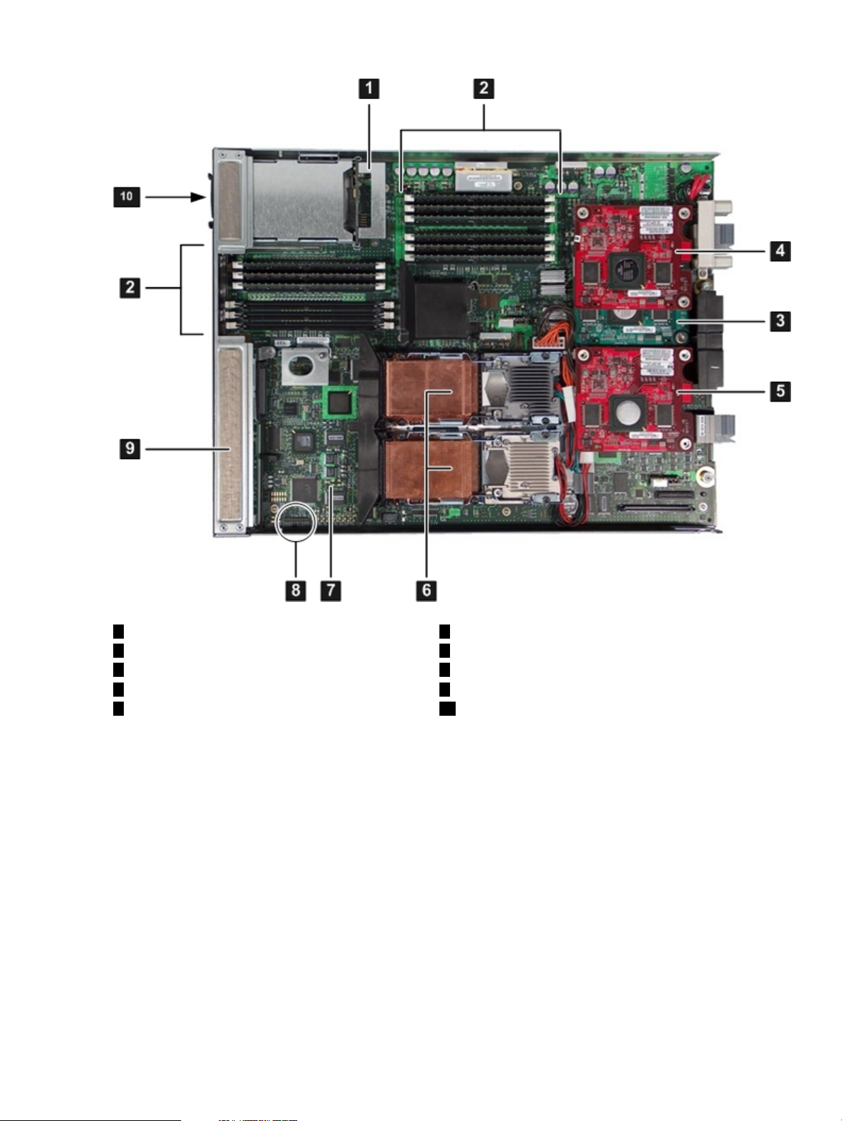
Figure 1-1 BL860c Server Blade Components
1
SAS backplane
2
DIMMs
3
Mezzanine card 1
4
Mezzanine card 2
SAS Disk Drives
There are two SAS disk drive slots on the BL860c server blade. The SAS disk drives have identical
LEDs that show the drive status.
Figure 1-2 shows the slot numbers of the SAS hard disk drives.
6
Processors
7
System board
8
Trusted Platform module
9
Front display panel
105
SAS disk drivesMezzanine card 3
22 Overview
Page 23
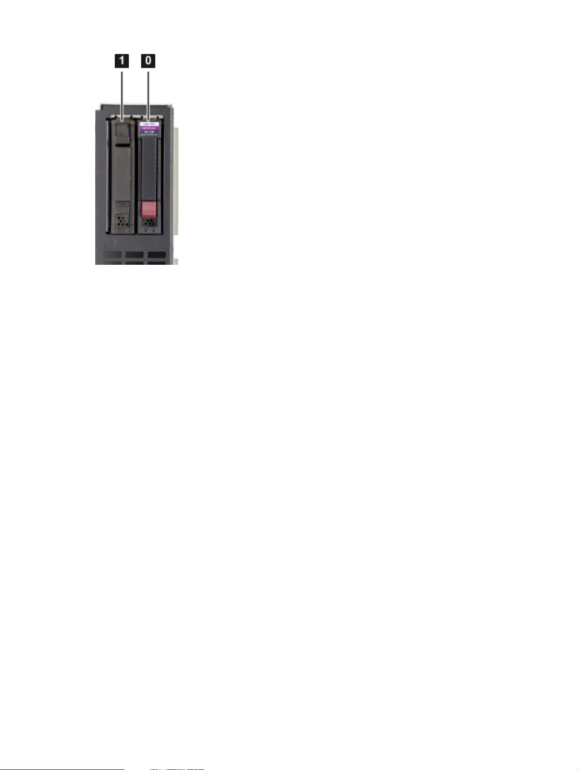
Figure 1-2 SAS Disk Drive Slots
For locations of the SAS disk drive LEDs, see Figure 1-5.
SAS Backplane
The SAS disk backplane supports two small form factor (SFF) hard disk drives. The backplane
supports hot-plugging a single SAS drive at a time. The activity LEDs and drive present LEDs
are controlled by a preprogrammed system-on-chip (PSOC). The system board hosts the SAS
controller, and supplies 12 V, 5 V, and 3.3 V standby power to the backplane. The backplane is
designed as a field-replaceable unit (FRU).
The SAS backplane is connected to the system board with a right angle connector. This connector
is specifically designed for high-speed differential applications, and supports server speeds
exceeding 5 Gigabits per second. Power, Sense, and I2C signals are routed through this connector
as well as the SAS differential pairs and SGPIO signals.
I/O Subsystem
The I/O subsystem is composed of embedded core I/O, and up to three mezzanine cards. One
type I and two type II mezzanine cards (with PCI express links that serves as a bridge between
the zx2 rope links and PCIe) are supported. The server blade does not support PCI Hot Plug
(PHP).
Memory controllers are used as the ropes to the PCI bridge for the system board fast and slow
core I/O. Two memory controllers are used to interface to the Core LAN and SAS. The memory
controllers run at 33 MHz and are used to interface with the manageability, USB, and graphics
through the SUV cable. The serial, USB, and video are provided through the PCI devices attached
to logical rope 0.
PCIe MPS Optimization
Each PCIedevice has a configurable maximum payload size (MPS) parameter. Larger MPS values
can enable the optimization to gain higherperformance. MPS Optimization is supported on PCIe
systems running HP-UX, Open VMS, and Linux. System firmware level greater than 01.01
performs an optimization during boot time to set the MPS value to the largest size supported by
the PCIe root port and the devices below it.
The default server state is optimization disabled. When disabled, system firmware sets MPS to
the minimum value on each PCIe device.
Server Blade Components 23
Page 24

The info io command displays the current PCIe MPS optimization setting. See Table C-1
(page 150).
To enable PCIe MPS optimization use the ioconfig mps_optimize command. See“ioconfig”
(page 162).
For non-PCIe systems, ioconfig and info io will not display the MPS optimization policy
setting. TheSet PCIe MPS Optimization boot manager menu also will not be displayed. Running
the ioconfig mps_optimize [on|off] command from a non-PCIe system, the following
output will be displayed:
------------Shell> ioconfig mps_optimize
ioconfig: PCIe MPS optimization is not supported.
Shell> ioconfig mps_optimize on
ioconfig: PCIe MPS optimization is not supported.
Exit status code: Unsupported
Shell>
-----------------
To restore MPS to the default values, enter the default clear command.
PCI Expansion Blade
If you need additional PCI-X/PCIe cards for your server blade, you can install a PCI expansion
blade. The PCI expansion blade holds up to one or two PCI-X or PCIe cards. However, you
cannot mix PCI-X and PCIe cards in the PCI expansion blade.
The PCI expansion blade must be installed adjacent to the server blade you are installing for it
to connect to the server blade properly.
For more information about the PCI expansion blade, see
http://h18004.www1.hp.com/products/blades/expansion/index.html?jumpid=reg_R1002_USEN.
Memory Subsystem
The server blade physical memory subsystem includes Double Data Rate Synchronous Dynamic
Random Access Memory (DDR2 SDRAM) DIMMs, as well as the memory bus traces,and required
termination. The memory subsystem supports only DDR2 SDRAM technology using
industry-standard DIMMs. The DIMMs use a 184-pin JEDEC standard connector. The server
blade memory subsystem provides two memory cells. Each cell is 144 bits wide (128 bits of data,
16 bits of ECC), and has six DIMM slots for a total of 12 slots (six DIMMs per cell). All 12 DIMM
slots are shared by both processors.
The minimum amount of memory supported in the server blade is 1 GB (two 512-MB DIMMs).
The maximum amount of memory supported in the server blade is 48 GB (twelve 4-GB DIMMs).
The DIMMsused in the server blade are low-profile (1.2” tall) DIMMs.Only HP qualified DIMMs
are supported.
DIMMs
The memory subsystem supports only DDR2 SDRAM technology utilizing industry-standard
1.2” high DIMMs. The DIMMs use a 184-pin JEDEC standard connector. You must install the
DIMMs in pairs. To enable chip sparing, install the DIMM in pairs. Both DIMMs must be the
same capacity. Table 1-2 summarizes the BL860c server blade memory configurations.
24 Overview
Page 25

Table 1-2 Server Blade Memory Array Capacities
NOTE: Installing DIMMs as a pair (two identical DIMMs) enables lock-step mode and chip
sparing.
Install DIMMs from highest capacity to lowest capacity (for example, install the 4-GB DIMMs
first, then the 2-GB DIMMs, then the 1-GB DIMMs, and so forth). Install memory DIMMs into
slots 0A and 0B first.
Power Subsystem
The power subsystem is located onthe systemboard. Each server blade receives bulk DC voltage
from the enclosure. The server blade power block converts the DC voltage from the enclosure
to the voltage required by the server blade. The BL860c server blade receives 12 V directly from
the enclosure. The voltage passes through E-Fuse circuitry that resides in the blade. The 12 V
supply is always on as long as a power supply is installed in the enclosure. A control line from
the enclosure onboard administrator (OA) can turn the E-Fuse on or off to supply or cut power
to the blade. The 12 V gets distributed to various point-of-load (POL) converters. The switched
POL voltage rails are: 0.9 V, 1.2 V, 1.5 V, 1.8 V, 2.5 V, 3.3 V, 5.0 V, 3.3 V standby, and 5.0 V standby.
Single DIMM SizesMin / Max Memory Size
512 MB1 GB / 6 GB
1 GB2 GB / 12 GB
2 GB4 GB / 24 GB
Processor and Core Electronics Complex
The BL860c processor subsystem accommodates one or two Intel Itanium dual-core processor
modules. It consists of the zx2 core electronics complex (CEC), a front side bus, a memory and
I/O controller, system clock generation and distribution, multiple POL converters, and I2C
circuitry for manageability and fault detection.
The front side bus speed is 267 MHz. The zx2 CEC and the processor modules are located on the
system board. A Zero Insertion Force (ZIF) socket connects the processors to the system board.
Heatsinks, processor metal frames, and bolster plates are part of the mechanical attach
requirements for the processors and the zx2.
Enclosure Information
This installation document covers only the BL860c server blade, and does not include specific
server blade enclosure information. For the server blade c-Class enclosure information, go to:
http://h71028.www7.hp.com/enterprise/cache/316735-0-0-0-121.html.
Controls, Ports, and LEDs
This section describes the controls, ports, and LEDs found on the front panel and rear panel of
your HP Integrity server blade.
For more information on LED functions and descriptions, see Chapter 5: “Troubleshooting”
(page 97).
Front Panel View
The server blade has seven server LEDs, one power button, two reset buttons, SAS disk drive
LEDs and one front panel port that accepts the serial, USB, video (SUV) cable for configuration
and troubleshooting. Figure 1-3 shows the LEDs, ports, and controls on the front panel of the
server blade.
Enclosure Information 25
Page 26
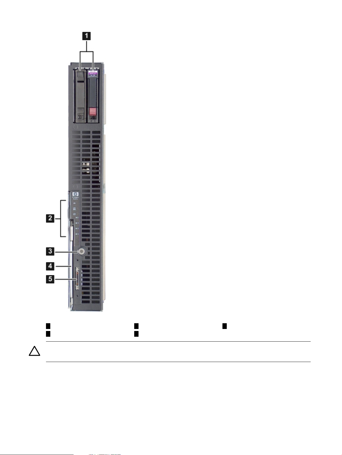
Figure 1-3 Server Blade Front View
1
SAS disk drives SUV cable port
CAUTION: Disconnect the local I/O cable from the I/O port when not in use. The connector is
not designed to provide a permanent connection.
Front Panel LEDs
The server blade contains seven LEDs on the front panel that indicate the server status.
Figure 1-4 shows the front panel LEDs.
26 Overview
Power button
42
Blade extraction handleFront panel LEDs
53
Page 27
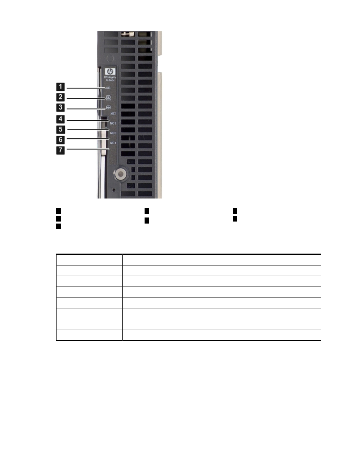
Figure 1-4 Front Panel LEDs on the BL860c Server Blade
1
UID LED
2 7
Server health LED NIC 4 LED
3
Internal health LED
Table 1-3 details the functions of the front panel LEDs.
Table 1-3 Integrity BL860c Server Blade Front Panel
SAS Disk Drive LEDs
There are two SAS disk drives on the BL860c server blade. They have identical LEDs that show
the drive status.
Figure 1-5 shows the locations of the SAS disk drive LEDs.
4
NIC 1 LED
5
NIC 2 LED
LED DescriptionItem
Unit identification (UID)1
Server health2
Internal health3
NIC 14
NIC 25
NIC 36
NIC 47
6
NIC 3 LED
Controls, Ports, and LEDs 27
Page 28
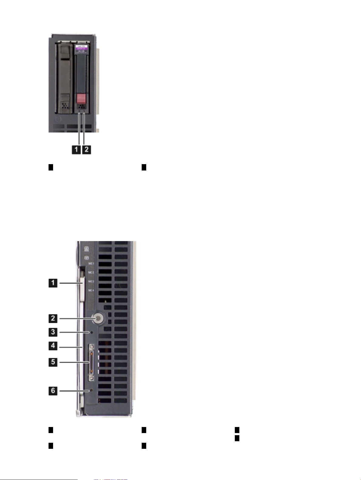
Figure 1-5 SAS Disk Drive LEDs
Controls and Ports
The following section identifies the locations and functions of the front panel controls and ports.
The power button, and server blade extraction lever, and the SUV cable port are located on the
front of the server. For more information about the power button and server blade power states,
see “Server Power States” (page 47).
21
Status LEDActivity LED
Figure 1-6 Front Panel Controls and Ports
1
28 Overview
Extraction lever release
button
3
iLO 2 MP reset pinhole
button
42
Extraction leverPower button
5
SUV port
6
Init (ToC) pinhole button
Page 29
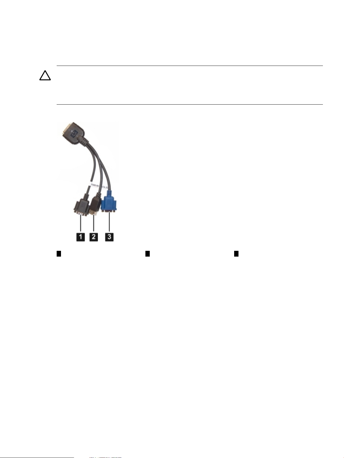
SUV Cable Port
The HP Integrity BL860c server blade has a serial, USB, and video (SUV) cable port located on
the front of the server blade. The SUV cable connects the server to external devices, such as: a
terminal emulator, an external DVD drive, or a monitor. Figure 1-7 shows the SUV cable attached
to the server blade.
CAUTION: The SUV cable is not designed to be used as a permanent connection.
Use caution when walking near the server blade when the SUV cable is installed. Hitting or
bumping the cable can cause the port on the server blade to break. This can damage the system
board, which will then need to be replaced.
Figure 1-7 SUV Cable Ports
Rear Panel View
Figure 1-8 shows the server blade rear panel ports.
321
Video portUSB ports (2)Serial port
Controls, Ports, and LEDs 29
Page 30
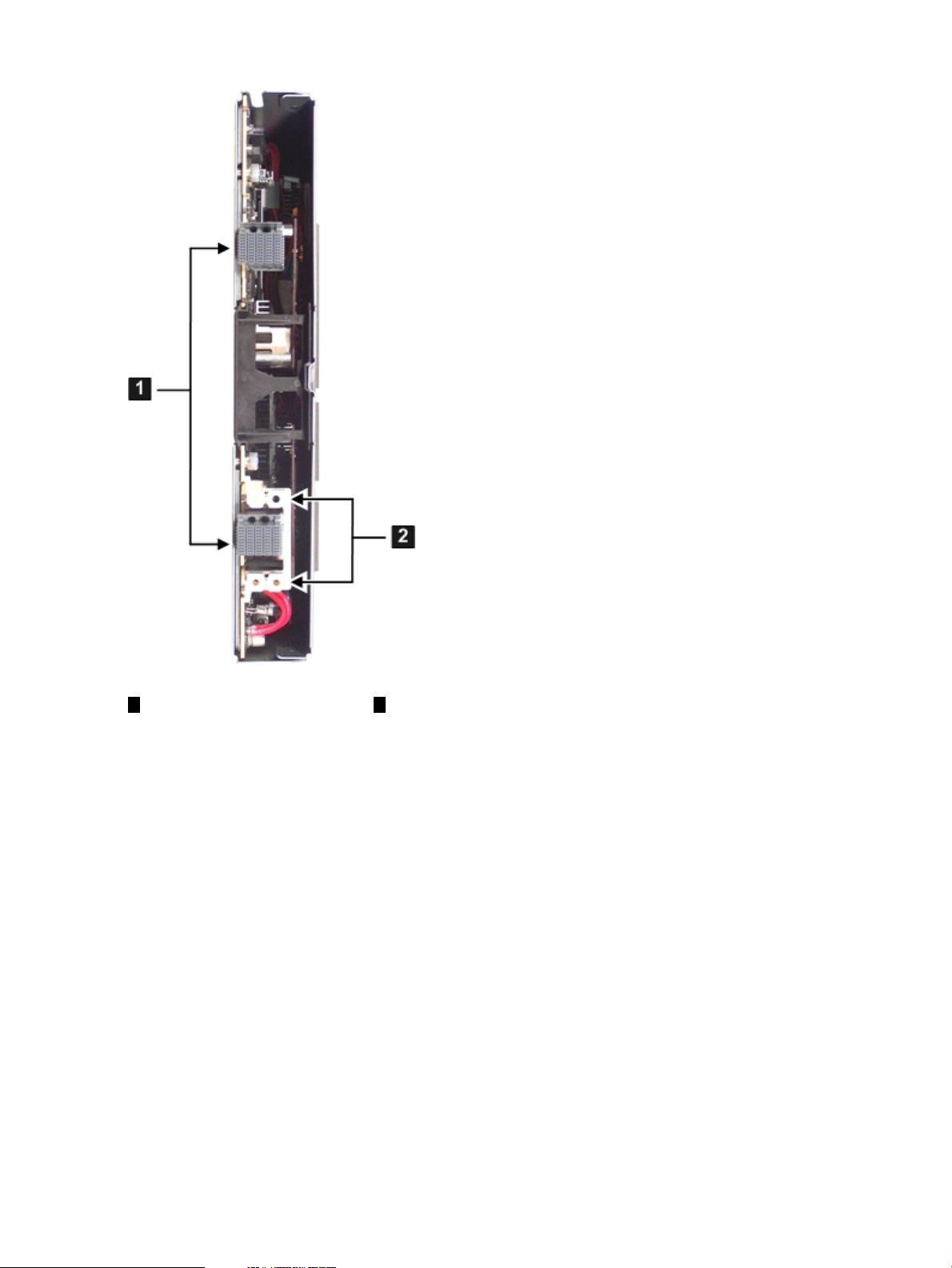
Figure 1-8 BL860c Server Blade Rear Panel Ports
21
Power connectorGBX signal connector
30 Overview
Page 31

2 General Site Preparation Guidelines
The HP Integrity BL860c server blade does not have cooling or power systems as part of the
server blade. Cooling and power is provided by the c-Class enclosure. Therefore, the server blade
power, cooling, and site specifications are included in the c-Class enclosure documentation.
For more information on the c-Class enclosures, go to:
http://h71028.www7.hp.com/enterprise/cache/316735-0-0-0-121.html.
For more site preparation information, go to www.docs.hp.com and click on Enterprise Servers,
Workstations, Systems Hardware. Select HP Integrity BL860c Server Blade in the list of servers
and select the Generalized Site Preparation Guidelines.
31
Page 32

32
Page 33

3 Installing the Server Blade into the Enclosure
This chapter covers the procedures for installing the HP Integrity BL860c server blade into a
c-Class enclosure.
This chapter addresses the following topics:
• “Safety Information” (page 33)
• “Installation Sequence and Checklist” (page 33)
• “Unpacking and Inspecting the Server Blade” (page 34)
• “Installing Additional Components” (page 35)
• “Installing and Powering On the Server Blade” (page 46)
• “Accessing the Integrated Lights Out Management Processor” (page 48)
• “Configuring the iLO 2 MP” (page 52)
• “Accessing EFI or the OS from iLO 2 MP” (page 57)
• “Server Blade to Enclosure Interface” (page 59)
• “LAN / NIC Configuration” (page 60)
• “Configuring the HP 2 Internal Port SAS Host Bus Adapter” (page 60)
• “Verify and Install the Latest Firmware” (page 73)
Safety Information
When removing and replacing server components, use care to prevent injury and equipment
damage . Many assemblies are sensitive to damage by electrostatic discharge.
Follow the safety precautions listed below to ensure safe handling of components, to prevent
injury, and to prevent damage to the server blade:
• When removing or installing a server blade or server blade component, follow the instructions
provided in this guide.
• Do not wear loose clothing that might snag or catch on the server or on other items.
• Do not wear clothing subject to static charge build-up, such as wool or synthetic materials.
• If installing an internal assembly, wear an antistatic wrist strap and use a grounding mat,
such as those included in the Electrically Conductive Field Service Grounding Kit.
• Handle components by the edges only. Do not touch metal-edge connectors or any electrical
components on accessory boards.
Installation Sequence and Checklist
The following is an overview of the steps to install the server blade into a c-Class enclosure, and
to get the server blade running. Follow the steps shown in Table 3-1 to ensure a successful server
installation.
Table 3-1 Installation Sequence Checklist
1
Unpack and inspect the server shipping container;inventory the contentsusing the packing
slip.
Install additional components shipped with the server.2
Install and power on the server blade.3
Install and power on the PCI expansion blade (if purchased).4
Configure iLO 2 MP access.5
Access iLO 2 MP.6
CompletedDescriptionStep
Safety Information 33
Page 34

Table 3-1 Installation Sequence Checklist (continued)
Access EFI or OS from iLO 2 MP.7
Download and install the latest firmware bundle from the HP support Web site.8
Install and boot the OS.9
Unpacking and Inspecting the Server Blade
This section describes procedures performed before installation. You must ensure that you have
adequately prepared your environment for your new server, received the components that you
ordered, and verified that the server and its containers are in good condition after shipment.
Verify Site Preparation
Verifying site preparation is an essential factor of a successful server installation, and includes
the following tasks:
• Gather LAN information: Determine the two separate IP addresses for the integrated Lights
Out Management Processor (iLO 2 MP) LAN and the server blade LAN.
• Establish a method to connect to the server console. For more information on console
connection methods, see Section : “Accessing the Integrated Lights Out Management
Processor” (page 48).
• Verify electrical requirements: Ensure that grounding specifications and power requirements
are met.
• Confirm environmental requirements.
CompletedDescriptionStep
Inspect the Shipping Containers for Damage
HP shipping containers protect their contents under normal shipping conditions. After the
equipment arrives, carefully inspect each carton for signs of shipping damage. Shipping damage
constitutes moderate to severe damage, such as punctures in the corrugated carton, crushed
boxes, or large dents. Normal wear or slight damage to the carton is not considered shipping
damage. If you find shipping damage to the carton, contact your HP customer service
representative immediately.
Unpack the Server Blade
The following procedure describes how to unpack a server blade.
1. Use the instructions printed on the outside top flap of the carton.
2. Remove inner accessory cartons and the top foam cushions.
IMPORTANT: Inspect each carton for shipping damage as you unpack the server.
3. Place the server blade on an antistatic pad.
Check the Inventory
The sales order packing slip lists the equipment shipped from HP. Use this packing slip to verify
the equipment has arrived.
34 Installing the Server Blade into the Enclosure
Page 35

NOTE: To identify each item by part number, see the sales order packing slip.
Damaged Equipment Returns
Immediately contact your HP customer service representative if the equipment is damaged. The
service representative initiates appropriate action through the transport carrier or the factory
and assists you in returning the equipment.
Installing Additional Components
This section describes the installation of components that are not installed at time of delivery. If
your server blade has no additional components to install, go to “Installing and Powering On
the Server Blade” (page 46)
This section addresses the following topics:
• “Service Tools Required” (page 35)
• “Adding a Hot-Plug SAS Disk Drive” (page 36)
• “Installing Internal Components” (page 38)
Service Tools Required
Service of this product requires the following tools:
The IPF Processor Install Tool Kit, consisting of:
• Disposable ESD Kit
• Processor installation tool (2.5 mm hex and Torx 15 screwdriver)
NOTE: If you purchased an additional processor, the IPF Processor Install Toolkit is included
with the processor.
The server blade has a Torx T–15 screwdriver mounted on the inside of the access panel.
Installing Additional Components 35
Page 36

Adding a Hot-Plug SAS Disk Drive
Use the following procedures if the server blade has a disk drive blank installed and you need
to install a hot-plug SAS disk drive.
For a list of supported SAS disk drives for the server blade, see
http://h18004.www1.hp.com/products/blades/components/c-class-storage.html
1. Press the release buttons simultaneously.
See Figure 3-1.
2. Pull the blank out of the drive bay.
Figure 3-1 Removing a Disk Drive Blank
CAUTION: Always populate hard drive bays with a SAS disk drive or a disk drive blank.
Operating the server blade without a SAS disk drive or disk drive blank causes improper
airflow and cooling that can lead to thermal damage to the server blade.
Install a SAS disk drive by performing the following steps:
1. Slide the drive into the cage until it is fully seated (1).
See Figure 3-2.
36 Installing the Server Blade into the Enclosure
Page 37

2. Close the lever to lock the drive into place (2).
Figure 3-2 Installing a Hot-Plug SAS Disk Drive
Installing Additional Components 37
Page 38

Installing Internal Components
Use these procedures to install internal components that were not installed into your server
blade. Before you can install the internal components, you must remove the access panel.
Removing the Access Panel
To remove the access panel, perform the following steps:
1. Unlock the cam on the access panel latch (if necessary) by turning the lock on the access
panel latch counterclockwise with a Torx T-15 or flathead screwdriver.
See Figure 3-3.
2. Pull up on the access panel latch (1).
This causes the access panel to slide back about 2 cm (0.75 in).
3. Remove the access panel by lifting it straight up and off the server blade (2).
Figure 3-3 Removing the Server Blade Access Panel
After the access panel is off, you can do the following:
• Add an additional processor.
See “Installing a Processor” (page 39).
• Add additional memory DIMMs.
See “Installing DIMMs” (page 40).
• Add additional mezzanine cards.
See “Installing Mezzanine Cards” (page 41)
38 Installing the Server Blade into the Enclosure
Page 39

Installing a Processor
Use this procedure to install an additional processor into the server blade.
To install a processor, perform the following steps:
1. Remove the dust cover from the empty processor 1 slot on the system board (if necessary).
Processor slot 0 has a processor installed in it.
For slot locations on the system board, see Figure 3-4.
Figure 3-4 Processor Slot Identification
2. Make sure the ZIF socket lock for the empty processor 1slot on the system board isunlocked
by turning the cam counter-clockwise 180 degrees with the processor installation tool (1).
If the socket lock does not turn, the socket is open and ready for the processor to be installed.
Figure 3-5 shows the ZIF socket lock in the unlocked position.
Figure 3-5 Unlocked ZIF Socket
CAUTION: Do not tighten the ZIF socket lock more than 180 degrees in either direction.
This severely damages the socket and processor, and renders the processor slot unusable.
3. Install the processor into processor slot 1 on the system board by lining up the alignment
pins on the processor with the holes in the processor slot.
4. Ensure the processor is seated by gently pressing down on the processor.
The processor should not move or rock back and forth. Reseat the processor if necessary.
Installing Additional Components 39
Page 40

5. Tighten the ZIF socket lock by turning the lock 180 degrees clockwise with the processor
installation tool. Press down gently on the processor when tightening the ZIF socket to
ensure the lock engages properly.
NOTE: Do not tighten the ZIF socket lock more than 180 degrees in either direction. This
severely damages the socket and processor, and renders the system board unusable.
6. To tighten the captive shoulder screws 1 through 4 on the processor, tighten them 2 full
turns once they engage the threads. When all four shoulder screws are engaged, tighten
them in the order shown in Figure 3-6 with the Torx T-15 screwdriver.
7. Tighten the captive screws (5– 6) on theprocessor until snug with the Torx T-15 screwdriver.
Figure 3-6 Installing a Processor on the Server Blade System Board
8. Connect the power cable to the processor power connector using the clips shown circled in
Figure 3-6 (page 40).
If you are only adding a processor to your server blade, and you are not adding memory DIMMs
or mezzanine cards, go to “Replacing the Access Panel” (page 45). If you are adding DIMMs,
go to “Installing DIMMs” (page 40). If you are adding mezzanine cards, go to “Installing
Mezzanine Cards” (page 41).
Installing DIMMs
There are twelve DIMM slots located on the BL860c system board. These DIMM slots are
designated in six ordered pairs; 0A – 0B, 1A – 1B, 2A – 2B, 3A – 3B, 4A – 4B, and 5A – 5B.
This is also the install order.
For DIMM slot locations, see Figure 3-7.
The server blade uses a minimum of 1 GB of memory (two 512–MB DIMMs), and a maximum
of 96 GB of memory (twelve 8–GB DIMMs). If you purchased additional memory, use these
procedures to install more memory into your server blade.
Install DIMMs from highest capacity to lowest capacity (for example, install the 4-GB DIMMs
first, then the 2-GB DIMMs, then the 1-GB DIMMs, and so forth).
DIMM sizes within each pair must match.
The memory subsystem supports chip spare functionality. The DIMM pairs must be identical to
allow chip sparing. If a multibit error occurs on an SDRAM, chip sparing allows that SDRAM
to be bypassed (logically replaced) on that DIMM.
To allow chip sparing functionality, use only HP DIMMs with the same part number.
40 Installing the Server Blade into the Enclosure
Page 41

Following is the install order for the DIMM pairs:
1. Slots 0A and 0B.
2. Slots 1A and 1B. .
3. Slots 2A and 2B.
4. Slots 3A and 3B.
5. Slots 4A and 4B.
6. Slots 5A and 5B.
Install additional memory DIMMs into the HP Integrity BL860c server blade by doing the
following:
1. Locate the DIMM slots on the server blade system board.
See Figure 3-7.
NOTE: The server blade ships with at least two DIMMs installed in slots 0A and 0B.
Figure 3-7 DIMM Slot Locations
2. Ensure the DIMM slot latches are open.
CAUTION: Use only HP low profile (1.2 in.) DIMMs. DIMMs from other sources may
adversely affect data integrity.
DIMMs do not seat fully if turned the wrong way.
DIMMs in a pair must be identical.
3. Insert a DIMM in a slot and push down firmly until the latches click shut.
Installing Mezzanine Cards
The HP Integrity BL860c server blade has three ports for mezzanine cards on the system board.
These cards provide I/O capabilities for the server blade. The server supports one Type I
mezzanine card, and two Type II mezzanine cards:
• The Type I mezzanine port supports an Intel PCIe x4 card
• The Type II mezzanine ports support Intel PCIe x8 cards
For more information regarding the different cards supported by the BL860c server blade, see
http://h71028.www7.hp.com/enterprise/cache/316682-0-0-0-121.html?jumpid=reg_R1002_USEN.
The available power rails for the mezzanine cards are 12 V, 3.3 V, and 3 V auxiliary, with a total
power of 25 W for each card.
Installing Additional Components 41
Page 42

Figure 3-8 shows the mezzanine port locations on the system board.
Figure 3-8 Mezzanine Port Locations on the System Board
1
Mezzanine port 1: PCI–e x4 port
2
Mezzanine port 2: PCI–e x8 port
3
Mezzanine port 3: PCI–e x8 port
The install order for the mezzanine cards is:
1. PCIe x4 card – Install into slot 1
2. PCIe x8 card – Install into slot 2
3. PCIe x8 card – Install into slot 3
NOTE: If you are only loading a PCIe x8 card, install it into slot 2 first.
Mezzanine port 1 is lower than mezzanine ports 2 and 3 to allow the cards to be stacked on top
of each other. Figure 3-9 shows the mezzanine port heights.
42 Installing the Server Blade into the Enclosure
Page 43

Figure 3-9 Mezzanine Port Heights
Installing a Mezzanine Card in Port 1
Use the following steps to insert a mezzanine card into the PCIe x4 port 1 on the system board.
1. Line up the plastic pins on the mezzanine card connector with the PCIe x4 port on the system
board.
2. Push down on the card directly above the port to seat the card into the port (1).
Installing Additional Components 43
Page 44

3. Tighten the thumbscrews on the mezzanine card until snug to secure the card to the system
board (2). See Figure 3-10.
Figure 3-10 Mezzanine Card 1 Installed on the Server Blade System Board
Installing a Mezzanine Card to Ports 2 and 3
Use the following steps to insert a mezzanine card into the PCIe x8 ports 2 and 3 on the system
board.
1. Line up the plastic pins on the mezzanine card connector on the PCIe x8 port 2 on the system
board.
2. Push down on the card directly above the port to seat the card into port 2.
3. Tighten the thumbscrews on the mezzanine card until snug to secure it to the system board.
4. Line up the plastic pins on the mezzanine card connector on the PCIe x8 port 3 on the system
board.
5. Push down on the card directly above the port to seat the card into port 3.
44 Installing the Server Blade into the Enclosure
Page 45

6. Tighten the thumbscrews on the mezzanine card until snug to secure it to the system board.
Figure 3-11 shows all three mezzanine cards installed on the server blade system board.
Figure 3-11 Mezzanine Cards 2 and 3 Installed on the Server Blade System Board
1
Mezzanine card 1 (PCI–e x4)
2
Mezzanine card 2 (PCI–e x8)
3
Mezzanine card 3 (PCI–e x8)
Replacing the Access Panel
To replace the access panel, perform the following steps:
1. Make sure the access panel latch is in the open position (pointing up).
See Figure 3-12 “Replacing the Access Panel”.
2. Place the access panel onto the server blade by lining up the posts on each side of the access
panel with the keyways on the server blade chassis (1).
3. Slide the access panel toward the front of the server blade (2), and push down on the access
panel latch until it is flush with the access panel (3).
Installing Additional Components 45
Page 46

Figure 3-12 Replacing the Access Panel
4. Lock the access panel cam (if necessary) by turning the cam clockwise with the Torx T–15
or flathead screwdriver.
Installing and Powering On the Server Blade
This section describes how to install the HP Integrity BL860c server blade into a standard c-Class
enclosure, and power it on. When you install the server blade into the enclosure, the server blade
powers up to standby mode.
Installing the Server Blade into the Enclosure
The following procedure shows how to install the server blade into a standard c-Class enclosure.
1. Remove the two half-height filler panels from the enclosure (if necessary).
2. Remove the half-height blade shelf (if necessary).
3. Ensure the extraction lever is released (open) on the server blade.
4. Slide the server blade into the enclosure.
See Figure 3-13.
46 Installing the Server Blade into the Enclosure
Page 47

5. Close the extraction lever (2).
The server blade should come up to standby power. The server blade is at standby power
if the server health LED is amber.
IMPORTANT: If the server health LED turns green, and the fan noise gets louder, then the
server blade has powered on automatically. Skip the rest of this procedure, and proceed to
“Accessing the Integrated Lights Out Management Processor” (page 48).
Figure 3-13 Installing a Server Blade into the Enclosure
Installing the PCI Expansion Blade
Use the following procedures to install the PCI expansion blade into the c7000 enclosure.
The PCI expansion blade must be installed adjacent to the server blade you are installing for it
to connect to the server blade properly.
1. Install PCI-X/PCIe cards into the PCI expansion blade.
2. Install the PCI expansion blade into the c7000 enclosure next to the server blade you installed.
For more information about the PCI expansion blade, see
http://h18004.www1.hp.com/products/blades/expansion/index.html?jumpid=reg_R1002_USEN.
Server Power States
The server blade has three power states: standby power, full power, and off. Install the server
blade into the enclosure to achieve the standby power state. By default, server blades are set to
power on to standby power when installed in a server blade enclosure. Verify the power state
by looking at the LEDs on the front panel, and using Table 3-2.
Installing and Powering On the Server Blade 47
Page 48

Table 3-2 Power States
Power States
Server Blade Installed
in Enclosure?
Front Panel Power
Button Activated?
Applied?
Powering On the Server Blade
Use the following procedure to power on the server blade after it is installed in the enclosure.
1. Ensure the server blade is in standby mode by verifying the power button LED is amber.
If the power button LED is green, the server blade has full power.
2. Press the power button momentarily to power on the server blade.
Accessing the Integrated Lights Out Management Processor
On the first installation of the BL860c server blade into the enclosure, you need to access the
Integrated Lights Out Management Processor (iLO 2 MP) on the server blade. To access the server
blade iLO 2 MP, use the Onboard Administrator iLO (OA/iLO) port on the rear of the enclosure,
or the RS-232 port on the SUV cable. Use the server blade iLO 2 MP for advanced troubleshooting,
diagnostics, and the initial network configuration of the server blade. There are two methods to
access the iLO 2 MP. Each way depends on how your server blade enclosure is set up at
installation:
• If the OA iLO port on the enclosure is connected to the local network that has a DHCP server,
your iLO 2 MP IP address is automatically generated by the DHCP server.
To access the iLO 2 MP through a DHCP server, see “Accessing the iLO 2 MP with DHCP
Enabled” (page 48).
DC Power Applied?Standby Power
NoYesNoYesStandby power
YesYesYesYesFull power
NoNoNoNoOff
• If the enclosure is not connected to a network, you must configure your server through the
serial port on the SUV cable.
To access the iLO 2 MP without a network connection, see “Accessing the iLO 2 MP with
No Network Connection” (page 50).
DHCP is default-enabled on the BL860c server blade.
To perform these procedures, the server blade enclosure must be powered on and operating
correctly.
Throughout this procedure, there are references to the OA/iLO and iLO 2 MP:
• OA/iLO refers to the enclosure Onboard Administrator iLO.
• iLO 2 MP refers to the server blade iLO Management Processor.
Accessing the iLO 2 MP with DHCP Enabled
Use this procedure to access the iLO 2 MP using DHCP. This procedure assumes that you have
a DHCP server connected to the same local network as your server blade, and the server blade
is installed into the enclosure. The server blade comes from the factory with DHCP enabled.
1. Use the display panel on the front of the enclosure to get the iLO 2 MP IP address.
The iLO 2 MP IP address is assigned by the DHCP server to the server blade.
2. Use the down arrow on the front display panel to highlight Blade or Port Info.
Figure 3-14 shows the Blade or Port Info selection highlighted on Main Menu of the front
display panel.
48 Installing the Server Blade into the Enclosure
Page 49

Figure 3-14 Main Menu of the Front Display Panel
3. Press the OK button.
The View Blade and Port Info screen displays on the front display panel. See Figure 3-15.
Figure 3-15 The View Blade and Port Info Screen
4. Using the left/right arrows, highlight Blade Info on the bottom of the front display panel.
5. Follow the onscreen directions to select the appropriate server blade, and press OK. The
View Blade Info screen displays.
See Figure 3-16.
Accessing the Integrated Lights Out Management Processor 49
Page 50

Figure 3-16 The View Blade Info Screen
6. Write down the iLO 2 MP IP address that displays on the View Blade Info screen.
7. Access The iLO 2 MP through telnet, SSH, or through the Web using the assigned DHCP
IP address.
8. This ends the “Accessing the iLO 2 MP with DHCP Enabled” procedure.
9. Continue to “Configuring the iLO 2 MP” (page 52).
Accessing the iLO 2 MP with No Network Connection
Use the following procedure to configure the RS-232 port to enable iLO 2 MP access. You need
to have a terminal emulator (for example, a laptop using hyperterm) to connect to the server
blade.
Connecting the SUV Cable to the Server Blade
Use the following procedure to connect your server blade to a terminal device using the SUV
port.
50 Installing the Server Blade into the Enclosure
Page 51

• Insert the SUV cable into the SUV port.
See Figure 3-17.
CAUTION: Disconnect the SUV cable from the port when not in use. The port and connector
are not intended to provide a permanent connection.
On the SUV cable, locking buttons are located on the sides of the server blade connector. Always
be sure to squeeze the locking buttons on the SUV cable connector before disconnecting the SUV
cable from the I/O port. Failure to do so can result in damage to the port.
Use caution when walking near the server blade when the SUV cable is installed. Hitting or
bumping the cable can cause the port on the server blade to break. This can damage the system
board, which will then need to be replaced.
Figure 3-17 Connecting the SUV Cable to the Server Blade
Accessing the Integrated Lights Out Management Processor 51
Page 52

Connecting a Terminal to the Server Blade
Use the following procedure to establish a connection from your server to your terminal (or
emulator device).
CAUTION: Disconnect the SUV cable from the port when not in use. The port and connector
are not intended to provide a permanent connection.
1. Connect the standard DB9f to DB9f modem eliminator cable to the RS–232 port on the SUV
cable. See Figure 3-18.
Figure 3-18 Serial Connector on the SUV Cable
2. Connect the other end of the DB9f to DB9f modem eliminator cable to your terminal device.
For more information about iLO 2 MP functions, see the HP Integrity Integrated Lights Out 2
Management Processor Operations Guide.
3. Verify that the parameters for RS–232 serial port communication are set to the following
values on your terminal or emulator device:
• VT 100 protocol
• 8/none (parity)
• 9600 baud
• None (receive)
• None (transmit)
4. Click OK to set the parameters.
5. If running an emulator, launch it now.
6. This ends the “Accessing the iLO 2 MP with No Network Connection” procedure.
7. Continue with “Configuring the iLO 2 MP” (page 52).
Configuring the iLO 2 MP
Use this procedure to configure iLO 2 MP settings after establishing a connection to iLO 2 MP
using one of the two methods discussed in Section : “Accessing the Integrated Lights Out
Management Processor”. This section also includes important security considerations when
configuring your server blade for remote access.
This section addresses the following topics:
• “Accessing iLO 2 MP After Establishing a Connection to the Server Blade” (page 53)
• “iLO 2 MP Security Requirements” (page 53)
52 Installing the Server Blade into the Enclosure
Page 53

Accessing iLO 2 MP After Establishing a Connection to the Server Blade
Depending on how you connect to the server blade, choose one of the following ways to access
the iLO 2 MP:
• Network connection (through OA iLO port)
1. From a network-accessible computer, open a telnet session.
2. Enter the iLO 2 MP address obtained in“Accessing the Integrated Lights Out
Management Processor” (page 48) in the appropriate screen.
You now have access to the iLO 2 MP functionality through the telnet session.
• Serial port connection
• Ensure you have an MP prompt.
• Log in to the iLO 2 MP by using the following default values for the login ID and password
(case sensitive):
Login: Admin
Password: Admin
You are now at the MP Main Menu screen.
iLO 2 MP Security Requirements
Depending on how you set up your server blade, there are security concerns regarding whether
you allow remote access to the server blade.
It is highly recommended that you allow remote access to the server blade. Remote access allows
for remote system event log analysis, troubleshooting, and general system administration.
Configuring the iLO 2 MP 53
Page 54

During the login process, a warning message displays. If you are logging in through a terminal
(either serial or telnet), an ASCII message scrolls by. If you are logging in through the web, a
pop-up window displays, requiring a response. Click OK. The warning message is as follows:
WARNING! MP ACCESS IS NOT SECURE
Default MP users are currently configured and remote access is enabled.
Modify default users passwords or delete users (see the user Administration page)
or
Disable all types of remote access (see the Access Settings page)
Regardless of how you plan to access iLO 2 MP, HP highly recommends that you change the
default MP password.
Depending on your required setup, continue with one of the following procedures:
• If you are allowing remote access, continue with “Securing Remote Access to the Server
Blade” (page 54)
• If you are not allowing remote access, continue with “Remote Access Not Allowed” (page 57).
Securing Remote Access to the Server Blade
If you choose to configure iLO 2 MP for remote access (using DHCP or a static IP address), use
the following steps to secure remote access to your server blade.
To secure remote access you need to change your MP password. Perform the following steps to
change your MP password:
1. From the MP Main Menu, enter CM to access the Command Menu.
The Command Menu displays.
2. From the Command Menu, enter UC to access the User Configuration Menu.
The User Configuration Menu displays.
3. From the User Configuration Menu, enter C to get to the Change Current User options.
4. Change 1-Admin by entering 1.
A list of options available to change displays.
5. Change your password by entering P.
Enter your new password in the dialog box.
Your password must be between 8 and 24 characters.
When you complete the password change procedure, iLO 2 MP disconnects you from the
server.
6. Re-establish your connection using the “Accessing iLO 2 MP After Establishing a Connection
to the Server Blade” (page 53) procedure with your new MP password.
7. This ends the “Securing Remote Access to the Server Blade” procedure.
Setting the Server Blade to Power On Automatically
The server blade comes from the factory set to power on to standby power. Use this procedure
to power on the server blade to full power when the server blade is inserted into the enclosure.
1. From the MP Main Menu, enter pr to access the Power Restore Configuration menu
2. Enter on to set the power restore configuration to power on to full power, as shown below:
54 Installing the Server Blade into the Enclosure
Page 55

3. Enter y to confirm changing the power restore configuration setting.
4. Power on the server through the iLO 2 MP by accessing the Power Control menu.
Access the Power Control menu by entering pc from the MP Main Menu
5. Enter on to power on the server blade as shown below:
6. Enter y to confirm changing the power control setting.
The server blade is now set to power on to full power when it is inserted into the enclosure.
Configuring Remote Access to the Server Blade
At this point in the iLO 2 MP configuration process, you must decide if the server blade will be
accessed remotely or not. Remote access allows the server blade to be stopped, started, configured,
and allows troubleshooting from a remote location. If you disable remote access, all configuring
and troubleshooting must be done through the SUV cable serial port.
Depending on your set up, go to one of the following procedures:
• Remote access allowed.
See “Remote Access Allowed” (page 56).
• Remote access not allowed.
See “Remote Access Not Allowed” (page 57).
Configuring the iLO 2 MP 55
Page 56

Remote Access Allowed
NOTE: If your server blade has a DHCP server connected to the OA/iLO port on the rear of
the enclosure, this procedure is not required. Proceed to “Accessing EFI or the OS from iLO 2
MP” (page 57).
To allow remote access, you should have changed your iLO 2 MP password to secure your server
blade. If you have a DHCP server connected to the OA/iLO port on the rear of the enclosure,
your access is set. However, if you do not have access to a DHCP server, you can allow remote
access using a static IP address (provided by your system administrator) that you enter into the
iLO 2 MP menu. Follow the steps below to assign a static IP address to your server blade.
CAUTION: If you have DHCP access through the OA/iLO port on the rear of the enclosure, do
not perform this procedure. This procedure is for assigning a static IP address for remote access
when a DHCP server is not connected to the enclosure.
If you do not have a DHCP server on your local network and are assigning a static IP address
to the server blade, you must disable DHCP on the server blade. Use the following steps to
disable remote access to your server blade, and add your static IP address, subnet mask, and
gateway address. Obtain these addresses from your system administrator.
1. From the MP Main Menu, enter the CM command to get to the MP Command Menu screen.
2. Enter the LC command to get to the LAN Configuration Menu screen.
The following displays:
At each prompt you may type DEFAULT to set default configuration or Q to Quit
Default LAN Configuration:
- - MAC Address :0x00110aa50058
D - DHCP status :Enabled
I - IP Address :127.0.0.1
M - MP Host Name :mp00110aa50058
S - Subnet Mask :255.255.255.0
G - Gateway Address :127.0.0.1
L - Link Status :Auto Negotiate
W - Web Console Port Number :2023
H - SSH Access Port Number :22
Enter parameter(s) to change. A to modify All. Or (Q) to Quit:
3. From the LAN Configuration Menu, enter d to access the DHCP Status screen.
4. Follow the onscreen instructions to change the DHCP status from Enabled to Disabled.
5. Enter y to confirm the DHCP status change.
6. From the LAN Configuration Menu, enter I to access the IP Address screen.
7. Follow the onscreen instructions to add the static IP address you obtained from your system
administrator.
8. From the LAN Configuration Menu, enter s to access the Subnet Mask screen.
9. Follow the onscreen instructions to add the subnet mask address you obtained from your
system administrator.
10. From the LAN Configuration Menu, enter g to access the Gateway Address screen.
11. Follow the onscreen instructions to add the gateway address you obtained from your system
administrator.
12. Confirm the changes were made by entering LC, and viewing the configuration screen.
13. The server blade is now set up for remote access with a static IP address.
56 Installing the Server Blade into the Enclosure
Page 57

Remote Access Not Allowed
If you do not want to allow remote access to the server blade, use the following steps to disable
DHCP and other remote connections on your server blade.
CAUTION: Only use this procedure if you are disabling remote access to the server blade.
Do not disable remote access if you have a DHCP server connected to the OA/iLO port on the
rear of the enclosure. This procedure disables all remote access to the server blade and you lose
your remote access the server blade.
1. From the MP Main Menu, enter the CM command to get to the MP Command Menu screen.
2. Enter the LC command to get to the LAN Configuration Menu screen.
The following displays:
At each prompt you may type DEFAULT to set default configuration or Q to Quit
Default LAN Configuration:
- - MAC Address :0x00110aa50058
D - DHCP status :Enabled
I - IP Address :127.0.0.1
M - MP Host Name :mp00110aa50058
S - Subnet Mask :255.255.255.0
G - Gateway Address :127.0.0.1
L - Link Status :Auto Negotiate
W - Web Console Port Number :2023
- - SSH Access Port Number :- (MP Feature Not Licensed)
- - IPMI / LAN Port Number :623
Enter parameter(s) to change. A to modify All. Or (Q) to Quit:
3. From the LAN Configuration Menu, enter D to get to the DHCP Status screen.
4. Follow the onscreen instructions to change the DHCP status from Enabled to Disabled.
5. From the LAN Configuration Menu, enter SA to get to the System Administration menu.
6. Disable Telnet, SSH, and web access by following the onscreen instructions.
7. Confirm the changes were made by entering LC, and viewing the configuration screen.
Your connection will be lost because you have just disabled remote access to the server
blade.
If you have disabled remote access. The only way access the server blade is through a direct
connection. This is done using the serial RS-232 port on the SUV cable (with an emulator
device). To directly connect to the server blade, see “Accessing the iLO 2 MP with No
Network Connection” (page 50).
Accessing EFI or the OS from iLO 2 MP
The extensible firmware interface (EFI) is an Itanium-based architecture feature that provides
an interface between the server blade OS and the server blade firmware. EFI provides a standard
environment for booting an OS and running preboot applications.
Use this procedure to access EFI or the OS from the iLO 2 MP. Your security parameters were
already set regarding remote access.
Accessing EFI or the OS from iLO 2 MP 57
Page 58

• From the MP Main Menu, enter co to access the Console Menu.
Depending on how the server blade was configured from the factory, and if the OS is installed
at the time of purchase, you should be in one of two places:
• EFI Boot Manager menu
• OS login prompt
If the server blade has a factory-installed OS, you can interrupt the boot process to configure
your specific EFI parameters.
If you are at the EFI shell prompt, go to “EFI Boot Manager” (page 58).
If you are at the OS login prompt, go to “Operating System Login Prompt” (page 58).
EFI Boot Manager
If you are at the EFI shell prompt, enter exit to get to the EFI Boot Manager Menu.
Saving EFI Configuration Settings
There are other EFI settings you may want to configure at this time. For more EFI configuration
options, see Appendix C (page 147).
After your EFI settings are configured, save your configuration settings using the NVRAM
backup utility to save EFI and other server blade settings. See “NVRAM Backup Utility” (page 147).
Booting and Installing the Operating System
From the EFI Boot Manager prompt, there are two ways to proceed, depending on if the OS is
loaded onto the server blade.
• If your OS is loaded onto your server blade, go to “Operating System is Loaded onto the
Server Blade” (page 58).
• If the OS is not installed onto your server blade, see “Operating System is Not Loaded onto
the Server Blade” (page 58).
Operating System is Loaded onto the Server Blade
If the OS is loaded on your server blade, Autoboot is the default setting. The server blade boots
to the OS.
• Use your standard OS logon procedures, or see your OS documentation to log on to your
OS.
Operating System is Not Loaded onto the Server Blade
There are two options on how to load the OS if it is not loaded onto your server blade.
• Load the OS from a CD. See “Installing the OS Using a USB DVD Drive and the OS Disks”
(page 75).
• Load the OS using HP-UX Ignite. See “Loading the Operating System Using HP-UX Ignite”
(page 58).
Loading the Operating System Using HP-UX Ignite
To install the OS using HP-UX Ignite, see: http://docs.hp.com/en/IUX/.
For EFI or HP-UX LAN configuration information, see “Server Blade to Enclosure Interface”
(page 59).
Operating System Login Prompt
If your server blade is at the OS login prompt after you establish a connection to the server blade,
use your standard OS log in procedures, or see your OS documentation for the next steps.
58 Installing the Server Blade into the Enclosure
Page 59

Server Blade to Enclosure Interface
This section describes the interface between the server blade and the server blade enclosure. This
sections also shows the RJ-45 LAN interconnect ports on the rear of the server blade enclosure,
and how they correspond with the Network Interface Controller (NIC) LEDs on the front of the
server blade.
Port Locations on the Rear of the Server Blade Enclosure
LAN port mapping depends on the type of I/O card that is installed into the server blade.
Figure 3-19 shows some of the modules available for the c-Class enclosure.
NOTE: This picture is used only to show the different modules, not where the modules should
be installed.
Figure 3-19 Interconnect Modules on the Rear of the Server Blade Enclosure
Server Blade to Enclosure Interconnect Mapping
Table 3-3 (page 59) shows how the HP Integrity BL860c server blade slots interconnect with the
slots on the c-Class enclosure.
Table 3-3 Server Blade to Enclosure Interconnect Mapping
HP Integrity BL860c Server Blade to c-Class Enclosure Mapping
Server Blade
NIC outputs or mezzanine slots
Enclosure
Interconnect Slots
Slots 1 and 2Ethernet NICs
Server Blade to Enclosure Interface 59
Page 60

Table 3-3 Server Blade to Enclosure Interconnect Mapping (continued)
HP Integrity BL860c Server Blade to c-Class Enclosure Mapping
NOTE: Dual-width interconnect modules cannot be used in slots 1 or 2.
Only single- or dual-port mezzanine cards are supported.
LAN / NIC Configuration
Table 3-4 shows how the EFI and HP-UX LAN ports and front panel NIC numbers match up on
the server blade enclosure.
Table 3-4 LAN / NIC Server Blade Enclosure Configuration
Slots 3 and 4Mezzanine Slot 1
Slots 5 and 6Mezzanine Slot 2
Slots 7 and 8Mezzanine Slot 3
HP-UX LAN#EFI LAN #Front Panel NIC #
LAN0Core LAN port 1NIC 1
LAN1Core LAN port 2NIC 2
LAN2Core LAN port 3NIC 3
LAN3Core LAN port 4NIC 4
Configuring the HP 2 Internal Port SAS Host Bus Adapter
The following information is provided to assist you in configuring the '2 Internal Port SAS host
Bus Adapter' (HBA) controller during installation.
For more information regarding SAS HBAs, see
http://docs.hp.com/en/netcom.html#SAS%20Host%20Bus%20Adapters.
To flash firmware, use the mptutil command. To configure and maintain the IR functionality
of the SAS controller on the HP Integrity server, use the drvcfg and cfggen EFI commands.
If you are scripting multiple devices, use the cfggen command.
MPTUTIL Utility
The mptutil utility enables you to update the adapter flash memory with the EFI driver and
HBA firmware. New versions of these images are released periodically.
IMPORTANT: Do not store the files in this package on a SAS device. If you store these files on
a SAS device and the update fails, these files are not accessible.
To update firmware, follow these steps:
1. Insert the HP IPF Offline Diagnostics and Utilities CD in the drive and boot to the EFI Shell.
You can also download the firmware image file and update utility from the HP Web site at
http://www.hp.com in the Driver Downloads section.
IMPORTANT: When you boot EFI-enabled servers, the CD containing the utility must be
in the drive to allow device mapping. The EFI utility and firmware image files are located
in the root directory or in a subdirectory on the CD.
The CD drive displays in the list of mapped devices as fs0.
60 Installing the Server Blade into the Enclosure
Page 61

2. To change to this device, enter fs0:
shell> fs0:
fs0:\>
3. To determine the current version of the firmware, follow these steps.
a. At the EFI Shell, enter mptutil from the directory that contains mptutil.efi.
The following example indicates that the EFI Serial Attached SCSI card utility version
is 1.01.12.00:
fs0:\EFI\HP\TOOLS\NETWORK> mptutil
MPTUTIL-1.01.12.00
Vendor Device
Choice ID ID Bus Device
------ ------ ------ --- ----- 0 1000h 0054h 14h 01h LSI Logic SAS1068 Host Adapter
1 - Refresh
b. Press Enter.
4. To update the firmware, use the mptutil command.
5. Reset the controller.
fs0:\> reset
The mptutil commands and functions are listed in Table 3-5 and described in the following
sections.
Table 3-5 MPTUTIL Commands and Functions
mptutil -f <firmware_file>
mptutil -o -g <x86_file> <fcode_file>
mptutil -o -vpd -c 0
Parameters in < > are optional. A space is required between command line options and their parameters.
Flashing Firmware on First Controller
To update the HBA RISC firmware on the first controller, follow these steps:
1. At the fs0:\> prompt, enter mptutil -f <firmware_file> -c 0.
2. At the fs0:\> prompt, enter reset.
The filename is optional and you are prompted for a filename if it is omitted.
Another way to flash the firmware executes without your knowledge. When mptutil is
executed, and a SAS HBA is in any state other than ready or operational, mptutil immediately
performs a firmware download boot. The firmware provided by you to do the firmware download
boot is immediately flashed after the firmware download boot has completed.
The mptutil command does this because the firmware only moves to the operational state if
it is running from flash and not memory. Operational state is needed to do everything else
provided in the utility.
FunctionCommand
Updating HBA RISC firmware on the controller
Updating EFI driver on first controller
Viewing VPD information
Flashing BIOS and EFI Driver on the First Controller
To update the EFI driver on the first controller, follow these steps:
1. At the fs0:\> prompt, enter mptutil -o -g <Bios_File> <EFI_driver_file>
-c 0.
2. At the fs0:\> prompt, enter reset.
The filename is optional and you are prompted for a filename if it is omitted.
Configuring the HP 2 Internal Port SAS Host Bus Adapter 61
Page 62

Common Questions About Flashing Firmware
Question After I update firmware on my SAS HBA, why doesn't the version string change
in the menu?
Answer The firmware you flashed on the HBA does not run until a diagnostic reset occurs.
If you exit the utility and reenter it, the version string is updated.
Question
Answer
Question How do I program multiple cards in a server from the command line?
Answer
Question Can I program a new flash and option ROM in the same command line argument?
Answer
This image does not contain a valid nvdata image when I try to flash the
firmware. Why?
You are expected to concatenate a proper nvdata image on to the firmware.
MPTUTIL prevents you from flashing an image without a proper concatenated
nvdata image. To concatenate the nvdata image and firmware, run the
mptutil -o -d 64it__l.fw,sas106x.dat,output.fw command.
• 64it__l.fw is the firmware image without an nvdata image
• sas106x.dat is the nvdata image. This file depends on the type/rev of
HBA on which the firmware is used.
• output.fw is the name of the file created with the firmware and nvdata
image concatenated. Use this concatenated image for all boards of this type
or revision.
MPTUTIL (EFI) does not support this.
Yes. Run the mptutil -f <firmware_name> -b <option_rom_name>
command.
Viewing the VPD Information for EFI Driver and RISC Firmware
To view the VPD information for the EFI driver and RISC firmware, at the fsO:\> prompt, enter
mptutil -o -vpd -c 0.
EFI Commands
To configure an Integrated Mirror (IM) Array on the SAS Controller, use the following EFI
commands:
• DRVCFG (GUI interface)
• CFGGEN (command line interface)
If you are not using the IM functionality, do not follow these procedures.
DRVCFG Utility
To configure an IM on the SAS controller, follow these steps:
Starting the DRVCFG Utility
To start the drvcfg configuration utility, follow these steps:
1. From the console menu, select the EFI Shell.
2. Enter drvcfg -s and press Enter.
Using the DRVCFG Utility
The configuration utility uses several input keys (F1, F2, HOME, END, and so on) that may not
be supported by all terminal emulation programs. Each key has an alternate key that performs
the same function. Review the terminal emulationprogram documentation to verify which input
keys are supported. If problems occur using the function keys or HOME/END/PGUP/PGDN, use
the alternate keys.
There are general key inputs throughout the configuration utility that apply on all screens:
62 Installing the Server Blade into the Enclosure
Page 63

F1 Help Context sensitive help for the cursor-resident field.
Arrow Keys Select up, down, left, or right to position the cursor.
Home/End Select up, down, left, or right to position the cursor.
+/- Use to change items with values in [ ] brackets are modifiable. Numeric keypad
+ and numeric keypad - (minus) update a modifiable field to its next relative
value.
Esc Use to abort the current context operation or exit the current screen. User
confirmation is solicited as required if changes were made by user. If you are
using a serial console, pressing Esc causes a delay of several seconds before it
takes effect. This is normal server behavior and is not an error.
Enter Use to execute a command. Executable items are indicated by highlighted text
and a different background color. Press Enter to execute the field's associated
function.
Configuration Utility Screens
All SAS BIOS configuration utility screens contain the following areas, starting at the top of the
screen:
Header area Identifies the utility and version number.
Menu area
Main area The main area for presenting data. This area has a cursor for item selection,
Footer area Provides general help information text.
Gives the title of the current screen and, on screens other than the Adapter
List screen, also identifies the adapter.
and horizontal and vertical scroll bars if necessary.
Figure 3-20 (page 63) provides a map of how to access screens in the drvcfg utility.
Figure 3-20 Accessed Screens in the drvcfg Utility
DRVCFG Utility Screens
The following screens display as part of the drvcfg utility.
Adapter List Screen
The Adapter List screen displays when the configuration utility starts. This screen displays a
scrolling list of up to 256 SAS controllers in the server, and provides information about each of
them. Use the arrow keys to select a SAS controller, and press Enter to view and modify the
selected SAS controller's properties.
Configuring the HP 2 Internal Port SAS Host Bus Adapter 63
Page 64

You can view and modify the SAS controller whether it is enabled or disabled. You can use the
Boot Support setting in the Adapter Properties menu to change the status of this setting. You
must reconnect the EFI Driver for a new Boot Support setting to take effect.
The following are the descriptions for the Adapter List screen.
Adapter Indicates the SAS Controller type
PCI Bus Indicates the PCI Bus number assigned by the system BIOS to an adapter (0x00
- 0xFF, 0 - 255 decimal)
PCI Dev Indicates the PCI Device assigned by the system BIOS to an adapter (range
0x00 - 0x1F, 0 - 31 decimal)
PCI Fnc Indicates the PCI Function assigned by the system BIOS to an adapter (range
0x00 - 0x7, 0 - 7 decimal)
FW Revision Displays the Fusion MPT firmware version and type (IR or IT)
Status Indicates whether the adapter is eligible for software control (Enabled,
Disabled, or Error)
Enabled Indicates the EFI Driver is either controlling the adapter, or will
attempt to control the adapter upon reload.
Disabled Indicates the EFI Driver is not controlling the adapter, or will
discontinue control of the adapter upon reload.
Error Indicates theEFI Driver encountered a problem with the adapter.
Viewing and modifying settings for the adapter is allowed but
the information and functionality available may be limited.
Adapter Properties Screen
The Adapter Properties screen enables you to view and modify adapter settings. To scan the
SAS controller’s devices, select a SAS controller and press Enter. The Adapter Properties screen
displays.
Figure 3-21 Adapter Properties Screen
Use the arrow keys to select RAID Properties, and press Enter to view the Select New Array
Type screen.
To access the following screens, use the arrow keys to select the screen, and press Enter for the
appropriate field:
• RAID Properties
• SAS Topology
• Advanced Adapter Properties
64 Installing the Server Blade into the Enclosure
Page 65

The following are descriptions for the Adapter Properties screen.
Adapter Indicates the specific SAS Controller type.
PCI Address Displays the PCI Address assigned by the system BIOS to the adapter.
• Bus value range 0x00 - 0xFF, 0 - 255 decimal
• Device value range 0x00 - 0x1F, 0 - 31 decimal
• Function range 0x00 - 0x7, 0 - 7 decimal
FW Revision
Displays the MPT firmware version and type. The format is x.xx.xx.xx-yy
where:
x.xx.xx.xx refers to the FW version
yy refers to the type.
The currently supported type is IR.l).
SAS Address Displays the SAS Address assigned to this adapter.
FW Revision Displays the Fusion MPT firmware version and type (IR or IT)
Status Indicates whether an adapter is eligible for configuration utility software
control or is reserved for control by other software (Enabled, Disabled or
Error).
Enabled Indicates the EFI Driver is controlling the adapter, or will
attempt to control the adapter upon reload.
Disabled Indicates the EFI Driver is not controlling the adapter, or will
discontinue control of the adapter upon reload.
Error Indicates the EFI Driver encountered a problem with the
adapter. Viewing and modifying settings for the adapter is
allowed but the information and functionality available may
be limited.
Boot Support Specifies whether an adapter is eligible for configuration utility software
control or is reserved for control by other software (Enabled BIOS & OS,
Enabled BIOS Only, Enabled OS Only or Disabled).
• Enabled BIOS & OS – SAS controller is controlled by the BIOS and OS
driver.
• Enabled BIOS Only – SAS controller is controlled by the BIOS. This
setting may not be supported by all OS drivers. For example, it is not
possible to disable an adapter in a Windows driver.
• Enabled OS Only – SAS controller is controlled by the OS driver.
• Disabled – SAS controller is not controlled by the BIOS when the SAS
controller is loaded. However, the adapter is visible through the
configuration protocol.
Changes to the Boot Support setting are reflected in the Status field of the
Adapter List menu. The new settings do not take effect until the BIOS is
reloaded (system reboot).
RAID Properties Screens
There are four screens within RAID properties. To access the screens, select RAID Properties
from the Adapter Properties screen. The Select New Array Type screen displays.
See Figure 3-22 (page 66).
Configuring the HP 2 Internal Port SAS Host Bus Adapter 65
Page 66

Figure 3-22 Select New Array Type Screen
Select New Array Type Screen
The Select New Array Type screen enables you to view an existing array or create an Integrated
Mirror array of two disks, plus an optional hot spare.
• To go to the Create New Array screen, select Create IM Volume.
• To go to the View Array screen, select View an Existing Array.
Create New Array Screen
The Create New Array screen enables you to create an array. To access the Create New Array
screen, press Enter on the Create IM Volume field from the Select New Array Type screen.
To create an array, follow these steps:
1. Select one of the following options:
To migrate to an IM array, press M.
This keeps the existing data, and the disk is synchronized.
To delete all data on all disks in the array, press D.
This overwrites data when creating a new IM array, and the disk is not synchronized.
2. To create the array after the volume is configured, press C.
The server prompts you to save changes, which creates the array. During the creation process,
the utility pauses. You are then taken back to the Adapter Properties screen.
Following are descriptions for the Create New Array screen.
Array Type Indicates the type of array being created.
Array Size Indicates the size of the array in Megabytes.
Bay Displays the bay where devices are located.
Device Identifier Displays the device identifier.
RAID Disk Specifies the devices (disks) that make up an IM array. If RAID Disk
is Yes, the device is part of an IM array; if No, the device is not part
of an IM array. This field is grayed out under the following conditions:
• The device does not meet the minimum requirements for use in
an IM array.
• The device is not large enough to mirror data on the primary
drive.
• This disk has been selected as the hot spare for the IM array.
66 Installing the Server Blade into the Enclosure
Page 67

Hot Spr
Specifies whether a device is the hot spare for an IM array. If Hot
Spr is Yes the device is used as a hot spare for the IM array. If Hot
Spr is No, the device is not used as a hot spare for the IM array. Only
one hot spare per IM array is permitted. A hot spare is not required
in an IM. You can specify a hot spare at array creation, or after
creation, if the array uses five disks or fewer. This field is grayed out
under the following conditions:
• The device does not meet the minimum requirements for use in
an IM array.
• The array has a hot spare.
• The array is made up of the maximum number of devices (six).
• The device isn't large enough to mirror data on the primary. The
hot spare drive must be greater than or equal to the size of any
drive in an IM volume.
Drive Status Disk is online and fully functional.OK
Missing Disk is not responding.
Failed Disk has failed.
Initializing Disk is initializing.
CfgOffln Disk is offline at host's request.
User Fail Disk is marked failed at host's request.
Offline Disk is offline for some other reason.
Inactive Disk has been set to inactive.
Not Syncd Data on disk is not synchronized with the rest of
the array.
Primary Disk is the primary disk for a two disk mirror
and is OK.
Secondary Disk is the secondary disk for a two disk mirror
and is OK.
Wrg Type Device is not compatible for use as part of an IM
array.
Too Small Disk is too small to mirror data.
Max Dsks Maximum number of disks allowed for this type
of array has been reached or maximum number
of total IM disks on a controller has been reached.
No SMART Disk doesn't support SMART and cannot be used
in an RAID array.
Wrg Intfc Device interface (SAS) differs from existing IM
disks.
Pred Fail Indicates whether device SMART is predicting device failure (Yes,
No).
Size(MB) Indicates the size of the device in megabytes (megabyte = 1024 x 1024
= 1,048,576 bytes). If the device is part of a two-disk array, this field
reflects the size of the array, not the size of the disk. If the device is
part of a three or more disk array, this field is the size of the disk
within the array. When creating a striped array, the usable size of the
array is determined by the number of drives multiplied by the size
of the smallest drive in the array. In arrays consisting of different
sized drives, excess space on larger drives is unusable.
Configuring the HP 2 Internal Port SAS Host Bus Adapter 67
Page 68

View Array Screen
The View Array screen enables you to view the current array configuration. To access the View
Array screen, press Enter on the View Existing Array field from the Select New Array Type
screen.
You can perform the following actions on the View Array screen:
Following are descriptions for the View Array screen.
• To view the next array, press N.
• To create a new array, press C.
Array Displays the number of this array.
Identifier Displays the array identifier.
Type Displays the RAID type.
Scan Order Displays the array scan order.
Size (MB) Displays the array size.
Status Displays the array status.
Bay Displays the device bay location.
Device Identifier Displays the device identifier.
RAID Disk Specifies the devices (disks) that make up an IM array. If RAID Disk
is Yes, the device is part of an IM array, if No, the device is not part
of an IM array. This field is grayed out under the following conditions:
• The device does not meet the minimum requirements for use in
an IM array.
• The device is not large enough to mirror existing data on the
primary drive.
• This disk has been selected as the hot spare for the IM array.
Hot Spr
Specifies whether a device is the hot spare for an IM array. If Hot
Spr is Yes, the device is used as a hot spare for the IM array. If Hot
Spr is No, the device is not used as a hot spare for the IM array. Only
one hot spare per IM array is permitted.
A hot spare is not required in an IM. A hot spare can be specified at
array creation, or after creation, if the array uses 5 disks or fewer.
This field is grayed out under the following conditions:
• The device does not meet the minimum requirements for use in
an IM array.
• The array has a hot spare.
• The array is made up of the maximum number of devices (6).
• The device isn't large enough to mirror data on the primary. The
hot spare drive must be greater than or equal to the size of any
drive in any IM volume.
Drive Status Disk is online and fully functional.OK
Missing Disk is not responding.
Failed Disk has failed.
Initializing Disk is initializing.
CfgOffln Disk is offline at the host's request.
User Fail Disk is marked failed at host's request.
Offline Disk is offline for some other reason.
Inactive Disk has been set inactive.
Not Syncd Data on disk is not synchronized with the rest of
the array.
68 Installing the Server Blade into the Enclosure
Page 69

Primary Disk is the primary disk for a two disk mirror
and is OK.
Secondary Disk is the secondary disk for a two disk mirror
and is OK.
Wrg Type Device is not compatible for use as part of an IM
array.
Too Small Disk is too small to mirror data.
Max Dsks Maximum number of disks allowed for this type
of array has been reached, or maximum number
of total IM disks on a controller has been reached.
No SMART Disk doesn't support SMART and cannot be used
in an RAID array.
Wrg Intfc Device interface (SAS) differs from existing IM
disks.
Pred Fail Indicates whether device SMART is predicting device failure (Yes,
No).
Size(MB) Indicates the size of the device in megabytes (megabyte = 1024 x 1024
= 1,048,576 bytes). If the device is part of a two-disk array, this field
reflects the size of the array, not the size of the disk. If the device is
part of a three or more disk array, this field is the size of the disk
within the array.
When creating a striped array, the usable size of the array is
determined by the number of drives multiplied by the size of the
smallest drive in the array. In arrays consisting of different sized
drives, excess space on larger drives is unusable.
Manage Array Screen
The Manage Array screen enables you to manage the current array. To access the Manage Array
screen, select the appropriate field and press Enter on the Manage Array field from the View
Array screen.
The Manage Array screen enables you to perform the following actions:
Manage Hot Spare
To display a Hot Spare Management screen that has the same layout as the Create New Array
screen, press Enter for Manage Hot Spare. This field is grayed out under the following conditions:
• The array is inactive.
• The array is at its maximum number of devices.
• Non-IR firmware is used.
• IR is disabled. The array is inactive.
Synchronize Array
To synchronize the IM array, press Enter for Synchronize Array. The screen prompts you to
perform this action. Press Y for yes or N for no. This field is grayed out under the following
conditions:
• The array is inactive.
• The array does not need to be resynchronized.
• The adapter's MPT firmware does not support the feature
• Non-IR firmware is used.
• IR is disabled. The array is inactive.
Configuring the HP 2 Internal Port SAS Host Bus Adapter 69
Page 70

Activate Array
To activate an IM array, press Enter for Activate Array. The screen prompts you to perform this
action. Press Y for yes or N for no.
Delete Array
To delete the displayed IM array, press Enter for Delete Array. The screen prompts you to ask
if you want to perform this action. Press Y for yes and N for no.
Following are descriptions for the Delete Array screen.
Identifier Displays the identifier of this array.
Type Displays the RAID type.
Scan Order Displays the scan order of the array.
Size (MB) Displays the size of this array.
Status Displays the status of this array.
Exit the SAS Configuration Utility Screen
Because some changes only take effect when you exit the utility, exit the utility properly. To exit
the utility, follow these steps:
1. To return to the Adapter List from Adapter Properties, press ESC.
2. To exit the utility from the Adapter List, press ESC.
A similar exit screen is used when exiting most other screens, and can be used to save settings.
The exit screen shows some options that are grey, indicating they are not available. You can only
select available options. The exit choices are as follows:
• Are you sure you want to exit?
• Cancel Exit
• Save changes and reboot
• Discard changes and reboot
• Exit the Configuration Utility and Reboot
CFGGEN Utility
The cfggen utility is a command line utility that runs in the Linux, EFI, and Windows
Pre-Installation (WinPE) environments. It is a minimally interactive program that you execute
from a command line prompt, or a shell script.
The results from invoking this utility are communicated through the program status value that
is returned when the program exits.
Use the cfggen utility to create IM storage configurations on SAS controllers. Some cfggen
commands work only with SAS adapters in the EFI environment.
Starting CFGGEN
The cfggen utility is located on the HP IPF Offline Diagnostic and Utilities CD. To use cfggen,
follow these steps:
1. Insert the CD into the drive.
2. Boot the server to the EFI Shell prompt.
3. From the EFI Shell prompt, change to the CD drive:
shell> fs0: Enter
fs0:\>
4. Change to the directory that contains cfggen.efi:
fs0:\> cd EFI\HP\TOOLS\NETWORK Enter
fs0: EFI\HP\TOOLS\NETWORK>
70 Installing the Server Blade into the Enclosure
Page 71

5. From this directory, use cfggen.
CFGGEN Operation
The cfggen command is not case sensitive. You can enter cfggen commands and parameters
in uppercase, lowercase, or a mixture of the two. Use the following conventions in command
descriptions:
The cfggen command uses a command line interface.
Syntax: cfggen <controller #> <command> <parameters>
Use the following conventions in command descriptions:
• Text in italics must be entered exactly as shown on the command line
• Text surrounded by < > must be replaced with a required parameter.
• Text surrounded by [ ] may be replaced by an optional parameter.
• Parameters surrounded by { } must be entered one or more times, as appropriate for the
executed command.
• Command line definition characters(< >, [ ], and { }) cannot beentered on the command
line.
The cfggen command uses a command line interface.
Syntax: cfggen <controller #> <command> <parameters>
Separate the program name, controller number, command, and parameters fields with the ASCII
space character. The format of the parameters is command specific.
The program return value is returned to the user when the program exits. A value of 0 is returned
if the command is successful. Otherwise, a value of 1 is returned.
Rules for creating IM volumes and hot spare disks
When creating IM volumes and hot spare disks, the following rules apply:
• All disks that are part of an IM volume or a hot spare for an IM volume must be on the same
SAS controller.
• IM volumes are supported.
• Only two IM volumes (plus a global hot spare) per controller can be created.
• An IM array must have two disks.
• A hot spare disk cannot be created without at least one IM volume already created.
• The utility does not allow adding a hot spare disk type different from disk types in the
volume.
• With the AUTO command all drives used are the same type as the first available disk found,
and the size is limited to the size of the smallest disk.
CFGGEN Utility Commands
The following are the commands available for the cfggen utility.
CREATE Command
The CREATE command creates IM volumes on the SAS controller. Firmware and hardware
limitations for this family of cards limit the number of configurations that are possible.
Syntax
cfggen <controller #> create <volume type> <size> [qsync] [noprompt]
Parameters
<volume type> Volume type for the volume to be created. Valid value is IM.
Configuring the HP 2 Internal Port SAS Host Bus Adapter 71
Page 72

<size> Size of the IM volume in megabytes, or “MAX” for the maximum size
available.
[qsync] Quick synchronization of the volume created.
[noprompt] Eliminates warnings and prompts.
Operation
After a disk is added to an IM volume, its storage capacity might or might not be used depending
on drive capacity and volume capacity. For example, if you add a 36 GB disk to a volume that
only uses 9 GB of capacity on each disk drive, the remaining 27 GB of capacity on the disk is
unusable.
The disk identified by the first SCSI ID on the command line is assigned as the primary disk
when creating an IM volume. If the SAS controller is allowed to resynchronize the disks, the data
on the primary disk is available by accessing the newly created volume.
AUTO Command
The AUTO command automatically creates an IM volume on the SAS controllers. The volume
is created with the maximum number of disks available for use in the specified volume type.
The main difference between the AUTO command and the CREATE command is that with AUTO
command, you do not specify SCSI ID values for disks to use in the volume. The cfggen utility
uses the first disks it finds that are usable in the IM volume. Firmware and hardware limitations
for the family of controllers limit the number of configurations that are possible.
Syntax
cfggen <controller #> auto <volume type> <size> [qsync] [noprompt]
Parameters
<volume type> Volume type for the volume to be created. Valid value is IM.
<size> Size of the RAID volume in megabytes, or “MAX” for the maximum size
available.
[qsync] Quick synchronization of the volume created.
[noprompt] Eliminates warnings and prompts.
Operation
When AUTO creates an IM volume, the first disk found is assigned as the primary disk. If the
controller is allowed to resynchronize the disks, the data on the primary disk is available by
accessing the newly created volume. Reply Yes to complete the creation.
HOTSPARE Command
The HOTSPARE command creates a hot spare disk. The hot spare is added to hot spare pool 0.
Syntax
cfggen <controller #> HOTSPARE [DELETE] <Encl:Bay>
Parameters
<controller #> A SAS controller number between 0 and 255.
[DELETE] Specifies that the hot spare is to be deleted (Omit the DELETE keyword
to specify hot-spare creation).
<Encl>:<Bay> Enclosure number and Bay number that identifies the disk drive that will
become the hot spare.
72 Installing the Server Blade into the Enclosure
Page 73

Operation
The number of disks in an IM array plus the hot spare cannot exceed three. You can create only
one hot spare disk. Make sure the capacity of the hot spare disk is greater than or equal to the
capacity of the smallest disk in the logical drive. An easy way to verify this is to use the DISPLAY
command.
See “Rules for creating IM volumes and hot spare disks” (page 71).
Verify and Install the Latest Firmware
HP attempts to provide you with the most current version of firmware. However, there might
be instances when this is not the case.
To ensure that you have the latest version of firmware running on your server, verify the firmware
installed on your server blade. If your firmware isn't the latest, download the latest version of
firmware from the web and create a CD to install the firmware on the server. To install the
firmware onto your server blade, you must have an external USB DVD drive attached to the
server blade. To install an external DVD drive to your server blade, see “Operating System is
Not Loaded onto the Server Blade” (page 58).
Verify Latest Version of Firmware
To verify your firmware version, do the following:
1. Log in to the iLO 2 MP (serially or through a telnet session).
2. Enter co to get to the EFI Boot Manager Menu.
The current server blade firmware displays under System Overview on the EFI Boot
Manager Menu.
3. Go to http://www.hp.com/go/bizsupport.
4. Choose download drivers and software.
5. Choose Itanium-based servers from the Server category.
6. Choose your product from the servers listed.
7. Choose the OS.
8. Choose the firmware category you want to verify.
9. Compare the version of firmware available on the website to the version of firmware on the
server blade.
• If the firmware versions are the same, you don't need to update your firmware.
• If the firmware versions are different, update your firmware. Proceed to “Download
the Latest Version of Firmware” (page 73).
Download the Latest Version of Firmware
To download the latest version of firmware from the web, do the following:
1. Go to http://www.hp.com/go/bizsupport.
2. Choose download drivers and software.
3. Choose Itanium-based servers from the Server category.
4. Choose your product from the servers listed.
5. Choose the OS.
6. Choose the firmware category you want to download.
7. Download the firmware to a CD.
For more information regarding firmware updates, see the HP Integrity BL860c Server Blade User
Service Guide.
Verify and Install the Latest Firmware 73
Page 74

Install the Latest Version of Firmware on the Server
To install the firmware on the server:
1. Connect to the server console. See “Accessing the Integrated Lights Out Management
Processor” (page 48).
2. Make sure the external USB DVD drive is connected and turned on. See “Installing the OS
Using a USB DVD Drive and the OS Disks” (page 75).
3. Insert the CD with the copy of the latest version of firmware into the external DVD drive.
4. Use the EFI Boot Manager menu and boot to the drive that contains the CD with the updated
firmware.
5. Follow the instructions to update the firmware.
For more information regarding firmware updates, see the HP Integrity BL860c Server Blade User
Service Guide.
74 Installing the Server Blade into the Enclosure
Page 75

4 Booting and Shutting Down the Operating System
This chapter describes procedures for booting and shutting down operating systems that run on
the server blade. The operating systems that run on the server blade are HP-UX 11i Version 2
(B.11.23), HP OpenVMS v8.3, Microsoft Windows Enterprise Server 2003, Red Hat Enterprise
Linux 4 update 4, and Novell SuSE Linux Enterprise Server 10.
The following sections are included in this chapter:
• “Operating Systems Supported on the Server Blade” (page 75)
• “Booting and Shutting Down HP-UX” (page 79)
• “Booting and Shutting Down HP OpenVMS” (page 84)
• “Booting and Shutting Down Microsoft Windows” (page 88)
• “Booting and Shutting Down Linux” (page 92)
Operating Systems Supported on the Server Blade
HP supports the following operating systems on the server blade.
• HP-UX 11i Version 2 (B.11.23)
• HP OpenVMS v8.3
• Microsoft Windows Server 2003
• Red Hat Enterprise Linux 4 update 4
• Novell SuSE Linux Enterprise Server 10
Installing the Operating System onto the Server Blade
These are generalized operating system installation procedures. For more specific details regarding
OS installation, see your operating system documentation.
Installing the OS Using a USB DVD Drive and the OS Disks
Before you can install the OS from a DVD disk, you must connect an external USB DVD device.
To install the OS onto the server blade from a USB DVD, do the following:
1. Connect the Integrity SUV cable to the front of the server blade. See Figure 4-1.
Figure 4-1 Connecting a USB DVD Drive to the Server Blade
Operating Systems Supported on the Server Blade 75
Page 76

2. Connect the USB DVD cable to one of the USB ports on the SUV cable (2).
See Figure 4-2 for the ports on the SUV cable.
Figure 4-2 Ports on the SUV Cable
1
Serial port
2
USB ports (2)
3
Video port
3. Reset (or reconnect) the server blade, and reboot to EFI.
4. Turn on the external USB DVD device.
Installing the OS from the External USB DVD Device
Perform the following steps to install the OS from an external USB DVD device.
1. Insert the CD with the OS into the external USB DVD drive.
2. Use the EFI Boot Manager menu and boot to the drive that contains the CD with the OS.
3. From the boot menu, select EFI Shell (Built In).
4. At the EFI shell prompt, specify the device name (for example, fs1:) for the DVD and enter
the EFI install command, as in the following example.
If the device is not automatically selected, select the device name for the DVD and execute
install. For example, from the EFI shell prompt you see something similar to this:
Shell> fs1:
fs1:\> install
If you do not see the USB DVD drive, use the EFI Map command to list all the device names
from the EFI shell prompt. The list of devices displays automatically, and the install process
selects the device for you. The Map command displays the following (this may not match
completely:
Seg Bus Dev Fnc Vendor Device Slot
# # # # ID ID # Path
--- --- --- --- ------ ------ --- ----------00 00 02 01 0x103C 0x1048 XX Acpi(HWP0002,0)/Pci(2|1)# MP - rope 0
00 00 01 00 0x1033 0x0035 XX Acpi(HWP0002,0)/Pci(1|0)# USB - rope 0
00 00 01 01 0x1033 0x0035 XX Acpi(HWP0002,0)/Pci(1|1)# USB - rope 0
00 00 01 02 0x1033 0x00E0 XX Acpi(HWP0002,0)/Pci(1|2)# USB - rope 0
00 00 02 00 0x103C 0x1290 XX Acpi(HWP0002,0)/Pci(2|0)# MP - rope 0
00 20 01 00 0x1000 0x0030 XX Acpi(HWP0002,100)/Pci(1| # SCSI- rope 1
00 40 01 00 0x1077 0x2312 XX Acpi(HWP0002,200)/Pci(1|0) # FC - rope 2
00 40 01 01 0x1077 0x2312 XX Acpi(HWP0002,200)/Pci(1|1) # FC - rope 2
00 80 01 00 0x14E4 0x1648 XX Acpi(HWP0002,400)/Pci(1|0) # LAN - rope 4
00 80 01 01 0x14E4 0x1648 XX Acpi(HWP0002,400)/Pci(1|1) # LAN - rope 4
76 Booting and Shutting Down the Operating System
Page 77

00 80 03 00 0x14E4 0x1648 XX Acpi(HWP0002,400)/Pci(3|0) # LAN - rope 4
00 80 03 01 0x14E4 0x1648 XX Acpi(HWP0002,400)/Pci(3|1) # LAN - rope 4
The USB DVD device is the one shown in bold.
5. The OS now starts loading onto the server blade. Follow the on-screen instructions to fully
install the OS.
6. Continue with “Configuring System Boot Options” (page 77)
Installing the OS Using HP Ignite–UX
The Ignite-UX product is an HP–UX administration tool that helps you install the HP-UX OS on
multiple server blades on your network. Ignite–UX also allows you to:
• Create custom install configurations, (for use in multiple installations on server blades)
• Recover HP–UX server blades remotely
• Create custom recovery media including tape, CD and DVD
• Manage and monitor multiple server blade installation sessions
To install the OS onto the server blade using HP-UX Ignite, see the following HP documentation:
http://docs.hp.com/en/IUX/.
Installing the OS Using vMedia
Virtual media (vMedia) provides you with virtual devices that mimic physical hardware devices,
such as a virtual DVD drive that connects through the network to the server blade (as if they
were physically connected). The vMedia device can be a physical DVD drive on the server blade,
or it can be an image file stored on a local disk drive or network drive.
Booting from the iLO 2 MP DVD enables you to deploy an OS from a network drive to multiple
server blades, and perform disaster recovery of the failed OS. The iLO 2 MP device uses a
client-server model to perform the vMedia functions. The iLO 2 MP device streams the vMedia
data across a live network connection between the server blade and the host server. The vMedia
Java™ applet provides data to the iLO 2 MP as it requests it.
See the vMedia Chapter of the HP Integrity Integrated Lights Out Management Processor Operations
Guide for more information regarding loading the OS with vMedia. As of this printing the vMedia
information is in Chapter 11.
NOTE: Once the OS is loaded, make sure to save your nonvolatile memory settings to preserve
boot entries in case of blade failure.
Configuring System Boot Options
This section discusses the configurable system boot options on the HP Integrity BL860c server
blade, including the boot options list and the autoboot setting for the server.
• Boot Options List The boot options list is a list of loadable items available for you to choose
from the EFI Boot Manager menu. Ordinarily the boot options list includes the EFI Shell
and one or more operating system loaders.
The following example includes boot options for HP-UX, Linux, and the EFI Shell.
EFI Boot Manager ver 2.00 [14.62]
OS might use only the primary console set via boot manager or conconfig command
/----------------------------------\
/----------------------------------\ | System Overview |
| Boot Menu | | hp server BL860c |
| HP-UX Primary Boot: 0/2/1/0.... | | Serial #: USE7234MV8 |
| Internal Bootable DVD | | |
| EFI Shell [Built-in] | | System Firmware: 3.01 [4739] |
| iLO Virtual Media | | BMC Version: 5.20 |
| Core LAN Port 1 | | MP Version: T.02.17 |
| SuSE on fs0: | | Installed Memory: 6144 MB |
| HP-UX 11.31 from SAS disk | | |
Configuring System Boot Options 77
Page 78

| ------------------------------- | | CPU Logical |
| Boot Configuration | | Module CPUs Speed Status |
| System Configuration | | 0 2 1.4 GHz Active |
| Security Configuration | | 1 2 1.4 GHz Active |
| | | |
\----------------------------------/ | |
| |
| |
\----------------------------------/
Use ^ and v to change option(s). Use Enter to select an option
— To correctly view the operating system console messages, go to the Boot Configuration
Menu under the EFI Boot Manager menu.
From the Boot Configuration Menu, select Console Configuration.
The Console Configuration screen displays the current configuration of the system
console.
EFI Boot Manager ver 2.00 [14.62]
OS might use only the primary console set via boot manager or conconfig command
/----------------------------------\
/----------------------------------\ | System Overview |
| /-----------------------------------------------------------\ |
| HP-UX | Console Configuration | |
| In/---| P Serial Acpi(HWP0002,PNP0A03,0)/Pci(1|2) Vt100+ 9600 | |
| EF|^ | NC VGA Acpi(HWP0002,PNP0A03,0)/Pci(4|0) | |
| iL| Ad| | |
| Co| Ed\-----------------------------------------------------------/ |
| Su| Remo |
| HP| Edit O/---------------------------------------------------\ |
| --| AutoBo| Console Help Console Status | |
| Bo| BootNe| <ENTER> to enable/disable P - Primary |us |
| Sy| ------| P/p to select primary S - Secondary |ve |
| Se| Driver| T/t to select terminal type NC - Not Configured |ve |
| | Consol| B/b to select baud rate | |
\---| ------| | |
| System\---------------------------------------------------/ |
| | | |
\-------------------------/ \----------------------------------/
Use <^|v> to scroll <ENTER> to Select <ESC> or <X/x> for Previous Menu
Select the appropriate console configuration for you environment.
NOTE: When exiting the Console Configuration screen, be sure to save your changes
and perform a server reset to activate your configuration changes.
IMPORTANT: When selecting a console as Primary, all other consoles must be set to
NC to allow the OS console messages to display to the proper device. This applies to
all operating systems.
— To manage the boot options list for each server, use the EFI Shell, the EFI Boot Option
Maintenance Menu, or operating system utilities.
At the EFI Shell, use the bcfg command to support list and manage the boot options
list for HP-UX.
The EFI Boot Option Maintenance Menu providesthe Add a Boot Option, Delete Boot
Option(s), and Change Boot Order menu items (use this method if you must add an
EFI Shell entry to the boot options list).
Operating systemutilities for managing the boot options list include the HP-UX setboot
command.
See“Adding HP-UX to the Boot Options List” (page 79) for more details:
• Autoboot Setting The autoboot setting determines, at startup, whether a server
automatically loads the first item in the boot options list, or remains at the EFI Boot Manager
78 Booting and Shutting Down the Operating System
Page 79

menu. With autoboot enabled, EFI loads the first item in the boot options list after a
designated timeout period.
Configure the autoboot setting for an HP Integrity server using either the autoboot EFI
Shell command, or the Set Auto Boot Time Out menu item from the EFI Boot Configuration
menu.
Examples of autoboot commands for HP-UX:
— Disable autoboot from the EFI Shell by issuing autoboot off
— Enable autoboot with the default timeout value by issuing autoboot on
— Enable autoboot with a timeout of 60 seconds by issuing the autoboot time 60
— Set autoboot from HP-UX using setboot
— Enable autoboot from HP-UX using setboot -b on
— Disable autoboot using setboot -b off
Examples of autoboot commands for Linux:
• Disable autoboot from the EFI Shell by issuing autoboot off
• Enable autoboot with the default timeout value by issuing autoboot on
• Enable autoboot with a timeout of 60 seconds by issuing the autoboot 60
• Disable the automatic retries during autoboot by issuing autoboot -nr 0
For more information on the autoboot command, enter help autoboot.
Booting and Shutting Down HP-UX
This section covers booting and shutting down HP-UX on the server blade.
• To add an HP-UX entry to the boot options list, see “Adding HP-UX to the Boot Options
List” (page 79).
• To boot HP-UX, use the one of the following procedures:
— To boot HP-UX normally, see “HP-UX Standard Boot” (page 80)
HP-UX boots in multi-user mode.
— To boot HP-UX in single-user more, see “Booting HP-UX in Single-User Mode” (page 82).
— To boot HP-UX in LVM-maintenance mode, see“Booting HP-UX in LVM-Maintenance
Mode” (page 83).
• To shut down HP-UX, see “Shutting Down HP-UX” (page 84).
Adding HP-UX to the Boot Options List
This section describes how to add an HP-UX entry to the system boot options list.
You can add the \EFI\HPUX\HPUX.EFI loader to the boot options list from the EFI Shell or EFI
Boot Configuration menu (or in some versions of EFI, the Boot Options Maintenance Menu).
NOTE: On HP Integrity servers, the operating system installer adds an entry to the boot options
list.
Adding the HP-UX Boot Option
This procedure adds an HP-UX item to the boot options list from the EFI Shell.
Booting and Shutting Down HP-UX 79
Page 80

NOTE: To add an HP-UX boot option when logged in to HP-UX, use the setboot command.
For details, see the setboot(1M) manpage.
1. Access the EFI Shell environment.
a. Log in to iLO for Integrity and enter CO to access the system console.
When accessing the console, confirm that you are at the EFI Boot Manager menu (the
main EFI menu).
If you are at another EFI menu, choose the Exit option from the submenus until you
return to the screen with the EFI Boot Manager heading.
b. Choose the EFI Shell menu option from the EFI Boot Manager menu to access the EFI
Shell environment.
2. Access the EFI System Partition (fsX: where X is the file system number) for the device
from which you want to boot HP-UX.
For example, enter fs2: to access the EFI System Partition for the bootable file system
number 2. The EFI Shell prompt changes to reflect the file system currently accessed.
The full path for the HP-UX loader is \EFI\HPUX\HPUX.EFI and it should be on the
device you are accessing.
3. At the EFI Shell environment, use the bcfg command to manage the boot options list.
The bcfg command includes the following options for managing the boot options list:
• bcfg boot dump – Display all items in the boot options list for the server.
• bcfg boot rm # – Remove the item number specified by # from the boot options list.
• bcfg boot mv #a #b – Move the item number specified by #a to the position specified
by #b in the boot options list.
• bcfg boot add # file.efi "Description" – Add a new boot option to the position in
the boot options list specified by #. The new boot option references file.efi and is listed
with the title specified by Description.
For example, bcfg boot add 1 \EFI\HPUX\HPUX.EFI "HP-UX 11i" adds an
HP-UX 11i item as the first entry in the boot options list.
See the help bcfg command for details.
4. Exit the console and iLO for Integrity interfaces if you are finished using them.
Press Ctrl–B to exit the system console and return to the iLO 2 MP Main Menu. To exit the
MP, enter X at the Main Menu.
HP-UX Standard Boot
Use either of the following procedures to boot HP-UX:
• “Booting HP-UX (EFI Boot Manager)”; or
• “Booting HP-UX (EFI Shell)”
Booting HP-UX (EFI Boot Manager)
From the EFI Boot Manager menu, choose an item from the boot options list to boot HP-UX.
1. Access the EFI Boot Manager menu for the server on which you want to boot HP-UX.
Log in to iLO for Integrity and enter CO to choose the system console.
Confirm that you are at the EFI Boot Manager menu (the main EFI menu) when accessing
the console. If you are at another EFI menu, choose the Exit option from the submenus until
you return to the screen with the EFI Boot Manager heading.
80 Booting and Shutting Down the Operating System
Page 81

2. At the EFI Boot Manager menu, choose an item from the boot options list.
Each item in the boot options list references a specific boot device and provides a specific
set of boot options or arguments you use when booting the device.
3. Press Enter to initiate booting using the chosen boot option.
4. Exit the console and iLO 2 MP interfaces when finished using them.
Press Ctrl–B to exit the system console and return to the MP Main Menu. To exit the MP
Main Menu, enter X at the MP Main Menu.
Booting HP-UX (EFI Shell)
From the EFI Shell environment, boot HP-UX on a device by first accessing the EFI System
Partition (for example fs0:) for the root device, then enteringHPUXto initiate the loader.
1. Access the EFI Shell environment for the server on which you want to boot HP-UX.
Log in to the iLO for Integrity and enter CO to choose the system console.
Confirm that you are at the EFI Boot Manager menu (the main EFI menu) when accessing
the console. If you are at another EFI menu, choose the Exit option from the submenus until
you return to the screen with theEFI Boot Managerheading.
From the EFI Boot Manager menu, choose the EFI Shellmenu option to access the EFI Shell
environment.
The EFI shell displays all the files systems and block devices available.
2. At the EFI Shell environment, issue the map command to list all currently mapped bootable
devices.
The bootable file systems of interest typically are listed as fs0:, fs1:, and so on.
3. Access the EFI System Partition (fsX: where X is the file system number) for the device
from which you want to boot HP-UX.
For example, enter fs2: to access the EFI System Partition for the bootable file system
number 2. The EFI Shell prompt changes to reflect the file system currently accessed.
NOTE: The file system number might change each time it is mapped (for example, when
the server boots, or when you issue the map -r command).
4. When accessingthe EFISystem Partition for the desired boot device, issue the HPUX command
to initiate the HPUX.EFI loader on the device you are accessing.
The full path for the loader is \EFI\HPUX\HPUX.EFI. When initiated, the loader references
the \EFI\HPUX\AUTO file and proceeds to boot HP-UX using the default boot behavior
specified in the AUTO file.
You have 10 seconds to interrupt the automatic booting of the default boot behavior. Pressing
any key during this 10 second period stops the HP-UX boot process and enables you to
interact with the HPUX.EFI loader. To exit the loader (the HPUX> prompt) enter exit
(this returns you to the EFI Shell).
To boot the HP-UX operating system, do not type anything during the 10 second period
given for stopping at the HPUX.EFI loader.
Shell> map
Device mapping table
fs0 : Acpi(000222F0,269)/Pci(0|0)/(Pun8,Lun0)/HD(Part1,Sig72550000)
blk0 : Acpi(000222F0,269)/Pci(0|0)/(Pun8,Lun0)
blk1 : Acpi(000222F0,269)/Pci(0|0)/(Pun8,Lun0)/HD(Part1,Sig72550000)
blk2 : Acpi(000222F0,269)/Pci(0|0)/(Pun8,Lun0)/HD(Part2,Sig72550000)
blk3 : Acpi(000222F0,2A8)/Pci(0|0)/(Pun8,Lun0)
blk4 : Acpi(000222F0,2A8)/Pci(0|1)/(Pun2,Lun0)
Booting and Shutting Down HP-UX 81
Page 82

Shell> fs0:
fs0:\> hpux
(c) Copyright 1990-2002, Hewlett Packard Company.
All rights reserved
HP-UX Boot Loader for IA64 Revision 1.723
Press Any Key to interrupt Autoboot
\efi\hpux\AUTO ==> boot vmunix
Seconds left till autoboot - 9
5. Exit the console and iLO for Integrity interfaces when finished using them.
Press Ctrl–B to exit the system console and return to the MP Main Menu. To exit the MP
Main Menu, enter X at the MP Main Menu.
Booting HP-UX in Single-User Mode
Use the following procedure to boot HP-UX in single-user mode from the EFI shell.
Booting HP-UX in Single-User Mode (EFI Shell)
From the EFI Shell environment, boot in single-user mode by doing the following.
1. Stop the boot process at the HPUX.EFI interface (the HP-UX Boot Loader prompt, HPUX>)
2. Enter the boot -is vmunix command.
3. Access the EFI Shell environment for the server on which you want to boot HP-UX in
single-user mode.
Log in to the iLO for Integrity (MP) and enter CO to choose the system console.
Confirm that you are at the EFI Boot Manager menu (the main EFI menu) when accessing
the console. If you are at another EFI menu, choose the Exit option from the submenus until
you return to the screen with the EFI Boot Manager heading.
From the EFI Boot Manager menu, choose the EFI Shellmenu option to access the EFI Shell
environment.
4. Access the EFI System Partition by entering fsX.
where X is the file system number for the device used to boot HP-UX.
5. When accessingthe EFI System Partition for the desired boot device, issue the HPUXcommand
to initiate the \EFI\HPUX\HPUX.EFI loader on the device you are accessing.
6. Boot to the HP-UX Boot Loader prompt (HPUX>) by pressing any key within the 10 seconds
given for interrupting the HP-UX boot process. Use the HPUX.EFI loader to boot HP-UX
in single-user mode in the next step.
After you press a key, the HPUX.EFI interface (the HP-UX Boot Loader prompt, HPUX>)
launches. For help using the HPUX.EFI loader, enter the help command. To return to
the EFI Shell, enter exit.
fs0:\> hpux
(c) Copyright 1990-2002, Hewlett Packard Company.
All rights reserved
HP-UX Boot Loader for IA64 Revision 1.723
Press Any Key to interrupt Autoboot
\efi\hpux\AUTO ==> boot vmunix
Seconds left till autoboot - 9
[User Types A Key to Stop the HP-UX Boot Process and Access the HPUX.EFI Loader ]
82 Booting and Shutting Down the Operating System
Page 83

Type ’help’ for help
HPUX>
7. At the HPUX.EFI interface (the HP-UX Boot Loader prompt, HPUX>) enter the boot
-is vmunix command to boot HP-UX (the /stand/vmunix kernel) in single-user (-is)
mode.
HPUX> boot -is vmunix
> System Memory = 4063 MB
loading section 0
................................................... (complete)
loading section 1
........ (complete)
loading symbol table
loading System Directory(boot.sys) to MFS
....
loading MFSFILES Directory(bootfs) to MFS
......
Launching /stand/vmunix
SIZE: Text:25953K + Data:3715K + BSS:3637K = Total:33306K
Console is on a Serial Device
Booting kernel...
8. Exit the console and iLO for Integrity interfaces when finished using them.
Press Ctrl–B to exit the system console and return to the MP Main Menu. To exit the MP,
enter X at the MP Main Menu.
Booting HP-UX in LVM-Maintenance Mode
Use the following procedure to boot HP-UX in LVM-maintenance mode from the EFI shell.
From the EFI Shell environment, boot in LVM-maintenance mode by doing the following.
1. Stop the boot processat the HPUX.EFI interface (the HP-UX Boot Loader prompt, HPUX>).
2. Enter the boot -lm vmunix command.
3. Access the EFI Shell environment for the server on which you want to boot HP-UX in
LVM-maintenance mode.
Log in to the iLO for Integrity and enter CO to choose the system console.
Confirm that you are at the EFI Boot Manager menu (the main EFI menu) when accessing
the console. If you are at another EFI menu, choose the Exit option from the submenus until
you return to the screen with the EFI Boot Manager heading.
From the EFI Boot Manager menu, choose the EFI Shell menu option to access the EFI
Shell environment.
4. Access the EFI System Partition (fsX: where X is the file system number) for the device
from which you want to boot HP-UX.
5. When accessing the EFI System Partition for the desired boot device, issue the HPUX
command to initiate the \EFI\HPUX\HPUX.EFI loader on the device you are accessing.
6. Type any key within the 10 seconds given for interrupting the HP-UX boot process. This
stops theboot process at the HPUX.EFI interface (the HP-UX Boot Loader prompt, HPUX>).
7. At the HPUX.EFI interface, enter the boot -lm vmunix command to boot HP-UX (the
/stand/vmunix kernel) in LVM-maintenance (-lm) mode.
8. Exit the console and iLO for Integrity interfaces when finished using them.
Press Ctrl–B to exit the system console and return to the MP Main Menu. To exit the MP,
type X at the MP Main Menu.
Booting and Shutting Down HP-UX 83
Page 84

Shutting Down HP-UX
To shut down HP-UX running on a server, use the shutdown command. You have the following
options when shutting down HP-UX:
• Shut down and reboot an HP-UX server using shutdown -r
• Shut down and halt (power off) an HP-UX server using shutdown -h
For more information, see the shutdown(1M )manpage.
1. Log in to HP-UX running on the server that you want to shut down.
Log in to iLO for Integrity (MP) for the server and use the Console menuto access the system
console. Accessing the console through iLO for Integrity (MP) enables you to maintain
console access to the server after HP-UX has shut down.
2. Issue the shutdown command with the appropriate command-line options.
The command-line options you specify dictate the way in which HP-UX shuts down, and
whether the server is rebooted.
Use the following list to choose an HP-UX shutdown option for your server:
• Shut down HP-UX and halt (power off) the server using shutdown -h
Reboot a halted server by powering on the server using the PC command at the iLO
2 MP Command menu.
• Shut down HP-UX and reboot the server by issuing shutdown -r
Booting and Shutting Down HP OpenVMS
NOTE: Before booting or installing the OpenVMS operating system on the BL860c server, see
the following Web site for the Server Errata Sheet for OpenVMS on the HP Integrity BL860c
Server: http://www.docs.hp.com/en/hw.html.
Once you have reached the Enterprise Servers, Workstations and Systems Hardware site, click
the HP Integrity BL860c Server link and refer to documentation specific to OpenVMS.
This section has procedures for booting and shutting down HP OpenVMS on the HP Integrity
BL860c server, and procedures for adding OpenVMS to the boot options list.
• To add an OpenVMS entry to the boot options list, refer to “Adding OpenVMS to the Boot
Options List” (page 84).
• To boot HP OpenVMS on an entry-class HP Integrity server, refer to “Booting OpenVMS”
(page 85).
• To shut down HP OpenVMS, refer to “Shutting Down OpenVMS” (page 87).
Adding OpenVMS to the Boot Options List
This procedure adds an OpenVMS item to the boot options list from the EFI Shell.
84 Booting and Shutting Down the Operating System
Page 85

NOTE: If OpenVMS is already installed on the server blade, add OpenVMS to the boot options
list using the command procedure SYS$MANAGER:BOOT_OPTIONS.COM and following the
on-screen instructions.
1. Access the EFI Shell environment.
Log in to iLO 2 for Integrity and enter CO to access the system console.
When accessing the console, confirm that you are at the EFI Boot Manager menu (the main
EFI menu). If you are at another EFI menu, choose the Exit option from the submenus until
you return to the screen with the EFI Boot Manager heading.
From the EFI Boot Manager menu, choose the EFI Shell menu option to access the EFI
Shell environment.
2. Access the EFI System Partition (fsX: where X is the file system number) for the device
from which you want to boot HP-UX.
For example, enter fs2: to access the EFI System Partition for the bootable file system
number 2. The EFI Shell prompt changes to reflect the file system currently accessed.
The full path for the HP-UX loader is \EFI\VMS\VMS_LOADER.EFI and it should be on
the device you are accessing.
3. At the EFI Shell environment, use the bcfg command to manage the boot options list.
The bcfg command includes the following options for managing the boot options list:
• bcfg boot dump – Display all items in the boot options list for the server.
• bcfg boot rm # – Remove the item number specified by # from the boot options list.
• bcfg boot mv #a #b – Move the item number specified by #a to the position specified
by #b in the boot options list.
• bcfg boot add # file.efi "Description" – Add a new boot option to the position in
the boot options list specified by #. The new boot option references file.efi and is listed
with the title specified by Description.
For example, bcfg boot add 1 \EFI\VMS\VMS_LOADER.EFI “OpenVMS
V8.3–1H1” adds an OpenVMS item as the first entry in the boot options list.
See the help bcfg command for details.
4. Exit the console and iLO 2 for Integrity interfaces if you are finished using them.
Press Ctrl–B to exit the system console and return to the iLO 2 MP Main Menu. To exit the
MP, enter X at the Main Menu.
For more details, see the HP OpenVMS Version 8.3 for Integrity Servers Upgrade and Installation
Manual. Here is a link to the manual:
http://h71000.www7.hp.com/doc/83final/ba322_90045/index.html.
Booting OpenVMS
To boot OpenVMS on an BL860c server, use either of the following procedures:
• “Booting OpenVMS (EFI Boot Manager)” on page 89
• “Booting OpenVMS (EFI Shell)” on page 89
Booting OpenVMS (EFI Boot Manager)
To boot OpenVMS from the EFI Boot Manager menu, perform the following steps:
1. From the EFI Boot Manager menu, choose an item from the boot options list to boot
OpenVMS using the chosen boot option.
Booting and Shutting Down HP OpenVMS 85
Page 86

2. Access the EFI Boot Manager menu for the server on which you want to boot OpenVMS.
Log in to the iLO 2 MP and enterCOto choose the system console.
NOTE: When accessing the console, confirm that you are at the EFI Boot Managermenu
(the main EFI menu). If you are at another EFI menu, choose the Exit option from the
submenus until you return to the screen with the EFI Boot Manager heading.
3. At the EFI Boot Manager menu, choose an item from the boot options list.
Each item in the boot options list references a specific boot device and provides a specific
set of boot options or arguments to use when booting the device.
4. Press Enter to initiate booting using the chosen boot option.
5. Exit the console and iLO 2 MP interfaces when finished using them.
6. EnterCtrl-Bto exit the system console and return to the iLO 2 MP Main Menu.
7. Exit iLO 2 MP by typingXat the iLO 2 MP Main Menu.
Booting HP OpenVMS (EFI Shell)
From the EFI Shell environment, to boot OpenVMS on a device, first access the bootable partition
(for example fs0:) for the root device and enter \efi\vms\vms_loader.efi to initiate the
OpenVMS loader.
1. Access the EFI Shell environment for the server on which you want to boot OpenVMS.
Log in to the iLO 2 MP and enter CO to choose the system console.
NOTE: When accessing the console, confirm that you are at the EFI Boot Manager menu
(the main EFI menu). If you are at another EFI menu, choose the Exit option from the
submenus until you return to the screen with the EFI Boot Manager heading.
2. From the EFI Boot Manager menu, choose the EFI Shell menu option to access the EFI Shell
environment.
3. At the EFI Shell environment, issue themap -Fscommand to list all currently mapped
bootable devices.
The bootable file systems are listed as fs0:, fs1:, and so on.
4. Access the bootable partition (fsX: where X is the file system number) for the device you
want to boot OpenVMS.
For example, enter fs2: to access the bootable partition for the bootable file system number
2.
The EFI Shell prompt changes to reflect the file system currently accessed.
NOTE: The file system number might change each time it is mapped (for example, when
the server boots, or when the map -r command is issued).
5. When accessing the bootable partition for the desired boot device, issue the
\efi\vms\vms_loader command to initiate the vms_loader.efi loader on the device
you are accessing.
fs5:> \efi\vms\vms_loader.efi
HP OpenVMS Industry Standard 64 Operating System, Version V8.3-1H1
© Copyright 1976-2006 Hewlett-Packard Development Company, L. P.
%DECnet-I-LOADED, network base image loaded, version = 05.13.00
%SMP-I-CPUTRN, CPU #02 has joined the active set.
%SMP-I-CPUTRN, CPU #03 has joined the active set.
%SMP-I-CPUTRN, CPU #01 has joined the active set.
86 Booting and Shutting Down the Operating System
Page 87

%SYSINIT-I- waiting to form or join an OpenVMS Cluster
%VMScluster-I-LOADSECDB, loading the cluster security database
%EWA0, Auto-negotiation mode assumed set by console
%EWA0, Merl5704 located in 64-bit, 66-mhz PCI-X slot
%EWA0, Device type is BCM5704C (UTP) Rev B0 (21000000)
%EWB0, Auto-negotiation mode assumed set by console
%EWB0, Merl5704 located in 64-bit, 66-mhz PCI-X slot
%EWB0, Device type is BCM5704C (UTP) Rev B0 (21000000)
%PKA0, Copyright (c) 2001 LSI Logic, PKM V1.1.01 Chip LSISAS1068
%EWA0, Link up: 1000 mbit, full duplex, flow control disabled
6. Exit the console and iLO 2 MP interfaces when finished using them.
7. EnterCtrl-Bto exit the system console and return to the iLO 2 MP Main Menu. To exit the
iLO 2 MP, enter X at the iLO 2 MP Main Menu.
Shutting Down OpenVMS
This sectiondescribes how to shut down the HP OpenVMS operating system on an BL860c server.
From the OpenVMS DCL prompt, issue the @SYS$SYSTEM:SHUTDOWN command to shut
down the OpenVMS operating system. Use the following steps:
1. Log in to OpenVMS running on the server that you want to shut down.
Log in to the iLO 2 MP for the server and use the Console menu to access the system console.
Accessing the console through the iLO 2 MP enables you to maintain console access to the
server after HP OpenVMS has shut down.
Booting and Shutting Down HP OpenVMS 87
Page 88

2. At the OpenVMS DCL prompt issue the @SYS$SYSTEM:SHUTDOWN command and specify
the shutdown options in response to the prompts given.
NOTE: Use the command in step 2 when you shut down OpenVMS the first time. If you
have shut down OpenVMS more than once, use the $ shutdown command.
$@sys$system:shutdown
SHUTDOWN -- Perform an Orderly System Shutdown
on node NODE1
How many minutes until final shutdown [0]:
Reason for shutdown [Standalone]:
Do you want to spin down the disk volumes [NO]?
Do you want to invoke the site-specific shutdown procedure [YES]?
Should an automatic system reboot be performed [NO]?
When will the system be rebooted [later]:
Shutdown options (enter as a comma-separated list):
REMOVE_NODE Remaining nodes in the cluster should adjust quorum
CLUSTER_SHUTDOWN Entire cluster is shutting down
REBOOT_CHECK Check existence of basic system files
SAVE_FEEDBACK Save AUTOGEN feedback information from this boot
DISABLE_AUTOSTART Disable autostart queues
POWER_OFF Request console to power-off the system
BIB_STATE Request console to reboot all CPUs to the Itanium BIB state
Shutdown options [NONE]: REBOOT_CHECK
%SHUTDOWN-I-BOOTCHECK, performing reboot consistency check...
%SHUTDOWN-I-CHECKOK, basic reboot consistency check completed
%SHUTDOWN-I-OPERATOR, this terminal is now an operator's console
%SHUTDOWN-I-DISLOGINS, interactive logins will now be disabled
%SET-I-INTSET, login interactive limit = 0, current interactive value = 1
%SHUTDOWN-I-SHUTNET, the DECnet network will now be shut down
NOTE: Use the @SYS$SYSTEM:SHUTDOWN command onlywhen shutting down OpenVMS
for the first time. Use the $ shutdown command after the first shut down.
HP OpenVMS I64 currently does not support thePOWER_OFFshutdown option.
Booting and Shutting Down Microsoft Windows
This sectiondescribes how to boot and shut down Microsoft Windows, and how to add Windows
entries to the system boot options list.
• “Adding Microsoft Windows to the Boot Options List” (page 88)
• “Booting the Microsoft Windows Operating System” (page 90)
• “Shutting Down Microsoft Windows” (page 91)
Adding Microsoft Windows to the Boot Options List
To add a Microsoft Windows entry to the system boot options list you must do so from EFI by
using the \MSUtil\nvrboot.efi utility to import boot options from the
EFI\Microsoft\WINNT50\Boot00... file on the device from which Windows is loaded.
This procedure adds the Microsoft Windows item to the boot options list.
88 Booting and Shutting Down the Operating System
Page 89

NOTE: On HP Integrity servers, the operating system installer automatically adds an entry to
the boot options list.
1. Access the EFI Shell environment.
Log in to the iLO 2 MP and enter CO to access the system console.
When accessing the console, confirm that you are at the EFI Boot Manager menu (the main
EFI menu). If you are at another EFI menu, choose the Exit option from the submenus until
you return to the screen with the EFI Boot Manager heading.
From the EFI Boot Manager menu, choose the EFI Shell menu option to access the EFI
Shell environment.
2. Access the EFI System Partition (fsX: where X is the file system number) for the device
from which you want to boot Windows.
For example, enter fs2: to access the EFI System Partition for the bootable file system
number 2. The EFI Shell prompt changes to reflect the file system currently accessed.
The full path for the Microsoft Windows loader is
\efi\microsoft\winnt50\ia64ldr.efi and it should be on the device you are
accessing. However, you must only initiate this loader from the EFI Boot Menu and not from
the EFI Shell.
3. List the contents of the \EFI\Microsoft\WINNT50directory to identify the name of the
Windows boot option file (Boot00nn) that you want to import into the system boot options
list.
fs0:\> ls EFI\Microsoft\WINNT50
Directory of: fs0:\EFI\Microsoft\WINNT50
09/18/03 11:58a <DIR> 1,024 .
09/18/03 11:58a <DIR> 1,024 ..
12/18/03 08:16a 354 Boot0001
1 File(s) 354 bytes
2 Dir(s)
fs0:\>
4. At the EFI Shell environment, issue the \MSUtil\nvrboot.efi command to launch the
Microsoft Windows boot options utility.
fs0:\> msutil\nvrboot
NVRBOOT: OS Boot Options Maintenance Tool [Version 5.2.3683]
1. SUSE SLES 10
2. HP-UX Primary Boot: 0/0/1/0/0.2.0
* 3. Windows Server 2003, Datacenter
4. EFI Shell [Built-in]
* = Windows OS boot option
(D)isplay (M)odify (C)opy E(x)port (I)mport (E)rase (P)ush (H)elp (Q)uit
Select>
5. Use the Import command to import the Window boot option file.
Select> i
Enter IMPORT file path: \EFI\Microsoft\WINNT50\Boot0001
Imported Boot Options from file: \EFI\Microsoft\WINNT50\Boot0001
Press enter to continue
Booting and Shutting Down Microsoft Windows 89
Page 90

NOTE: Due to the type of server you purchased, your output may not exactly match the
output shown here.
6. Enter Q to quit the NVRBOOT utility, and exit the console and iLO 2 MP interfaces if you
are finished using them.
Enter Ctrl-B to exit the system console and return to the iLO 2 MP Main Menu. To exit the
iLO 2 MP, enter x at the Main Menu.
Booting the Microsoft Windows Operating System
Boot the Windows Server 2003 operating system on an HP Integrity server by using the EFI Boot
Manager menu to choose the appropriate Windows item from the boot options list. Refer to
“Shutting Down Microsoft Windows” (page 91) for details on shutting down the Windows
operating system.
1. From the EFI Boot Manager menu, choose an item from the boot options list to boot
Windows using the chosen boot option.
2. Access the EFI Boot Manager menu for the server on which you want to boot Windows.
Log in to the iLO 2 MP and enter CO to choose the system console.
When accessing the console, confirm that you are at the EFI Boot Manager menu (the main
EFI menu). If you are at another EFI menu, choose the Exit option from the submenus until
you return to the screen with the EFI Boot Manager heading.
3. At the EFI Boot Manager menu, choose an item from the boot options list.
Each item in the boot options list references a specific boot device and provides a specific
set of boot options or arguments to be used when booting the device.
4. Press Enter to initiate booting using the chosen boot option.
5. Once Windows begins loading, wait for the Special Administration Console (SAC) to become
available.
The SAC interface provides a text-based administration tool that is available from the system
console. For details refer to the SAC online help (enter ? at the SAC> prompt).
Loading.: Windows Server 2003, Datacenter
Starting: Windows Server 2003, Datacenter
Starting Windows...
********************************************************************************
Computer is booting, SAC started and initialized.
Use the "ch -?" command for information about using channels.
Use the "?" command for general help.
SAC>
NOTE: Due to the type of server you purchased, your output may not exactly match the
output shown here.
6. Exit the console and iLO 2 MP interfaces when finished using them.
Enter Ctrl-B to exit the console and return to the iLO 2 MP Main menu. To exit the iLO 2
MP, enter x at the Main menu.
90 Booting and Shutting Down the Operating System
Page 91

Shutting Down Microsoft Windows
Shut down the Windows operating system on HP Integrity servers by using the Start menu or
the shutdown command.
CAUTION: Do not shut down Windows using Special Administration Console (SAC) restart
or shutdown commands under normal circumstances.
Issuing restart or shutdown at the SAC> prompt causes the server to restartor shutdown
immediately and can result in the loss of data.
Instead use the Windows Start menu or the shutdown command to shut down gracefully.
To shut down Windows use either of the following methods.
• Choose Shut Down from the Star t menu and choose either Restart or Shut down from the
pull-down menu.
The Restart menu item shuts down and restarts the server. The Shut down menu item
shuts down the server.
You can use this method when using a graphical interface to the server.
• Issue the shutdown command from the Windows command line.
Refer to “” (page 91) for details.
You can issue this command from a command prompt through the Special Administration
Console (SAC) or from any other command line.
The Windows shutdown command includes the following options:
/s Shuts down and halts (power off) the server. This is the equivalent of
Start—>Shut Down, Shut down. To power on the server, use the iLO 2 MP PC
command.
/r Shuts down and restarts the server. This is the equivalent of Start—>Shut Down,
Restart.
/a Aborts a server shutdown.
/t xxx Sets the timeout period before shutdown to xxx seconds. The timeout period
ranges from 0–600, with a default of 30.
Refer to the help shutdown Windows command for details.
Shutting Down Windows from the Command Line
From the Windows command line, issue the shutdown command to shut down the operating
system.
1. Log in to Windows running on the server that you want to shut down.
For example, access the system console and use the Windows SAC interface to start a
command prompt, from which you can issue Windows commands to shut down the server.
2. Check to see whether any users are logged in.
Use the query user or query session command.
Booting and Shutting Down Microsoft Windows 91
Page 92

3. Issue the shutdown command and the appropriate options to shut down the Windows
Server 2003 on the server.
You have the following options when shutting down Windows:
• To shut down Windows and reboot: shutdown /r or choose the Start —> Shut
Down action and choose Restart from the pull-down menu.
• To shut down Windows and halt (power off server hardware): shutdown /s or choose
the Start —> Shut Down action and choose Shut down from the pull-down menu.
To reboot a halted server you must power on the server using the PC command at the
iLO 2 MP Command menu.
• To abort a shutdown (stop a shutdown that has been initiated): shutdown /a
For example:
shutdown /r /t 60 /c "Shut down in one minute."
This command initiates a Windows system shutdown and reboot after a timeout period of
60 seconds. The /c option specifies a message that is broadcast to any other users of the
server.
Booting and Shutting Down Linux
This section covers booting and shutting down Linux on the server blade. Procedures for Red
Hat Enterprise Linux and SuSE Linux Enterprise Server are given in this section.
• To add a Linux entry to the boot options list, refer to “Adding Linux to the Boot Options
List” (page 92).
• To boot Linux, use the following procedures.
— Refer to “Booting the Red Hat Enterprise Linux Operating System” (page 93) for details
on Red Hat Enterprise Linux.
— Refer to “Booting the SuSE Linux Enterprise Server Operating System” (page 94) for
details on SuSE Linux Enterprise Server.
• To shut down either Red Hat Enterprise Linux or SuSE Linux Enterprise Server, refer to
“Shutting Down Linux” (page 95).
Adding Linux to the Boot Options List
This section describes how to add a Linux entry to the system boot options list. The processes
for adding both Red Hat Enterprise Linux and SuSE Linux Enterprise Servers are given here.
You can add the \EFI\redhat\elilo.efi loader or the \efi\SuSE\elilo.efi loader
to the boot options list from the EFI Shell or EFI Boot Configuration menu (or in some versions
of EFI, the Boot Option Maintenance Menu).
NOTE: On HP Integrity servers, the operating system installer automatically adds an entry to
the boot options list.
1. Access the EFI Shell environment.
Log in to the iLO 2 MP and enter CO to access the system console.
When accessing the console, confirm that you are at the EFI Boot Manager menu (the main
EFI menu). If you are at another EFI menu, choose the Exit option from the submenus until
you return to the screen with the EFI Boot Manager heading.
From the EFI Boot Manager menu, choose the EFI Shell menu option to access the EFI
Shell environment.
92 Booting and Shutting Down the Operating System
Page 93

2. Access the EFI System Partition (fsX: where Xis the file system number) for the device
from which you want to boot Linux.
For example, enter fs2: to access the EFI System Partition for the bootable file system
number 2. The EFI Shell prompt changes to reflect the file system currently accessed.
The full path for the Red Hat Enterprise Linux loader is \EFI\redhat\elilo.efi and
it should be on the device you are accessing.
The full path for the SuSE Linux Enterprise Server loader is \efi\SuSE\elilo.efi and
it should be on the device you are accessing.
3. At the EFI Shell environment, use the bcfg command to manage the boot options list.
The bcfg command includes the following options for managing the boot options list:
• bcfg boot dump – Displays all items in the boot options list for the server.
• bcfg boot rm # – Removes the item number specified by #from the boot options list.
• bcfg boot mv #a #b – Moves the item number specified by #a to the position specified
by #b in the boot options list.
• bcfg boot add # file.efi "Description" – Adds a new boot option to the position
in the boot options list specified by #. The new boot option references file.efi and is listed
with the title specified by Description.
For example, bcfg boot add 1 \EFI\redhat\elilo.efi "Red Hat
Enterprise Linux" adds a Red Hat Enterprise Linux item as the first entry in the
boot options list.
Likewise, bcfg boot add 1 \efi\SuSE\elilo.efi "SLES 10" adds a SuSE
Linux item as the first entry in the boot options list.
Refer to the help bcfg command for details.
4. Exit the console and iLO 2 MP interfaces if you are finished using them.
Enter Ctrl-B to exit the system console and return to the iLO 2 MP Main Menu. To exit the
iLO 2 MP, enter x at the Main Menu.
Booting the Red Hat Enterprise Linux Operating System
You can boot theRed Hat Enterprise Linux operating system on HP Integrity servers using either
of these methods:
• Choose a Red Hat Enterprise Linux entry from the EFI Boot Manager menu.
To load the Red Hat Enterprise Linux operating system at the EFI Boot Manager menu,
choose its entry from the list of boot options.
Choosing a Linux entry from the boot options list boots the operating system using
ELILO.EFI loader and the elilo.conf file.
• Initiate the ELILO.EFI Linux loader from the EFI Shell.
Refer to “” (page 94) for details.
On a Red Hat Enterprise Linux boot device EFI System Partition, the full paths to the loader
and configuration files are: \EFI\redhat\elilo.efi and \EFI\redhat\elilo.conf.
After choosing the file system for the boot device (for example, fs0:) initiate the Linux
loader from the EFI Shell prompt by entering the full path for the ELILO.EFI loader.
By default the ELILO.EFI loader boots Linux using the kernel image and parametersspecified
by the default entry in the elilo.conf file on the EFI System Partition for the boot device.
To interact with the ELILO.EFI loader, interrupt the boot process (for example, type a space)
at the ELILO boot prompt. To exit the ELILO.EFI loader, use the exit command.
Booting and Shutting Down Linux 93
Page 94

Booting Red Hat Enterprise Linux from the EFI Shell
Use this procedure to boot Red Hat Enterprise Linux from the EFI Shell.
1. Access the EFI Shell.
From the system console, choose the EFI Shell entry from the EFI Boot Manager menu to
access the shell.
2. Access the EFI System Partition for the Red Hat Enterprise Linux boot device.
Use the EFI shell map command to list the file systems (fs0, fs1, and so on) that are known
and mapped.
To choose a file system to use, enter its mapped name followed by a colon (:). For example,
to operate with the boot device that is mapped as fs3, enter fs3: at the EFI Shell prompt.
3. Enter ELILO at the EFI Shell command prompt to launch the ELILO.EFI loader.
If needed, you can specify the loader path by entering \EFI\redhat\elilo at the EFI
Shell command prompt.
4. Allow the ELILO.EFI loader to proceedwith booting the Red Hat Enterprise Linux kernel.
By default, the ELILO.EFI loader boots the kernel image and options specified by the
default item in the elilo.conf file.
To interact with the ELILO.EFI loader, interrupt the boot process (for example, type a
space) at the ELILO boot prompt. To exit the loader, use the exit command.
Booting the SuSE Linux Enterprise Server Operating System
You can boot the SuSE Linux Enterprise Server 10 operating system on HP Integrity servers
using either of these methods:
• Choose a SuSE Linux Enterprise Server entry from the EFI Boot Manager menu.
To load the SuSE Linux Enterprise Server operating system at the EFI Boot Manager menu,
choose its entry from the list of boot options.
Choosing a Linux entry from the boot options list boots the operating system using
ELILO.EFI loader and the elilo.conf file.
• Initiate the ELILO.EFI Linux loader from the EFI Shell. Refer to “Booting SuSE Linux
Enterprise Server from the EFI Shell” (page 94) for details.
On a SuSE Linux Enterprise Server boot device EFI System Partition, the full paths to the
loader and configuration files are: \efi\SuSE\elilo.efi and
\efi\SuSE\elilo.conf.
After choosing the file system for the boot device (for example, fs0:) you can initiate the
Linux loader from the EFI Shell prompt by entering the full path for the ELILO.EFIloader.
By default, the ELILO.EFI loader boots Linux using the kernel image and parameters specified
by the default entry in the elilo.conf file on the EFI System Partition for the boot device.
To interact with the ELILO.EFI loader, interrupt the boot process (for example, type a space)
at the ELILO boot prompt. To exit the ELILO.EFI loader, use the exit command.
Booting SuSE Linux Enterprise Server from the EFI Shell
Use this procedure to boot SuSE Linux Enterprise Server 10 from the EFI Shell.
1. Access the EFI Shell.
From the system console, choose the EFI Shell entry from the EFI Boot Manager menu to
access the shell.
94 Booting and Shutting Down the Operating System
Page 95

2. Access the EFI System Partition for the SuSE Linux Enterprise Server boot device.
Use the map EFI Shell command to list the file systems (fs0, fs1, and so on) that are
known and mapped.
To choose a file system to use, enter its mapped name followed by a colon (:). For example,
to operate with the boot device that is mapped as fs3, enter fs3: at the EFI Shell prompt.
3. Enter ELILO at the EFI Shell command prompt to launch the ELILO.EFI loader.
If needed, you can specify the loader path by entering \efi\SuSE\elilo at the EFI Shell
command prompt.
4. Allow the ELILO.EFI loader to proceed with booting the SuSE Linux kernel.
By default, the ELILO.EFI loader boots the kernel image and options specified by the
default item in the elilo.conf file.
To interact with the ELILO.EFI loader, interrupt the boot process (for example, type a
space) at the ELILO boot prompt. To exit the loader, use the exit command.
Shutting Down Linux
Use the shutdown command to shut down Red Hat Enterprise Linuxor SuSE Linux Enterprise
Server.
The Red Hat Enterprise Linux and SuSE Linux Enterprise Server shutdown command has the
following options:
-h
Halts (power off) after shutdown.
Use the PC command at the iLO 2 MP Command menu to manuallypower on or power
off server hardware, as needed.
-r
-c
time When to shut down (required.) You can specify time in any of the following ways:
Refer to the shutdown(8) Linux manpage for details. Also refer to the Linux manpage for the
poweroff command.
1. From the command line for Red Hat Enterprise Linux or SuSE Linux Enterprise Server, issue
2. Log in to Linux running on the server you want to shut down.
3. Issue the shutdown command with the desired command-line options, and include the
Reboots after shutdown
Cancels an already running shutdown
• Absolute time in the format hh:mm. hh is the hour (one or two digits) and mm is the
minutes (two digits).
• Number of minutes to wait in the format +mm, in which mm is the number of
minutes.
• now to immediately shut down; this is equivalent to using +0 to wait zero minutes.
the shutdown command to shut down the operating system.
required time argument to specify when the operating system shutdown is to occur.
For example, shutdown -r +20 shuts down and reboots the server in twenty minutes.
Booting and Shutting Down Linux 95
Page 96

96
Page 97

5 Troubleshooting
The purpose of this chapter is to provide a preferred methodology (strategies and procedures)
and tools for troubleshooting server blade error and fault conditions.
The following sections are included in this chapter:
• “Methodology” (page 97)
• “Troubleshooting Tools” (page 102)
• “Errors and Error Logs” (page 109)
• “Supported Configurations” (page 112)
• “Troubleshooting Processors/Memory/SBA” (page 114)
• “Enclosure Information” (page 25)
• “Cooling Subsystem” (page 115)
• “Troubleshooting Communications Modules ” (page 115)
• “Troubleshooting Management Subsystem ” (page 116)
• “Boot Process LEDs” (page 106)
• “Firmware” (page 116)
• “Troubleshooting the Server Interface (System Console)” (page 117)
• “Troubleshooting the Environment” (page 118)
• “Reporting Your Problems to HP” (page 118)
Methodology
General Troubleshooting Methodology
There are multiple entry points to the troubleshooting process, dependent upon your level of
troubleshooting expertise; the tools, processes, and procedures which you have at your disposal;
and the nature of the server fault or failure.
1. Typically, you select from a set of symptoms, ranging from very simple, server LED is
blinking; to the most difficult, Machine Check Abort (MCA) has occurred. The following is
a list of symptom examples:
• Front Panel LED blinking
• System Alert present on system console
• Server blade won’t power-up
• Server blade won’t boot
• Error/Event Message received
• MCA occurred
2. Narrow down the observed problem to the specific troubleshooting procedure required.
Isolate the failure to a specific part of the server blade to perform more detailed
troubleshooting. For example:
• Problem - Front Panel LED blinking
Methodology 97
Page 98

NOTE: The front panel health LED flashes amber with a warning indication, or flashes
red with a fault indication.
— System Alert on system console?
— Analyze the alert by using the system event log (SEL), to identify the last error
logged by the server blade. Use the iLO 2 MP commands to view the SEL, through
the MP’s text interface.
3. You should have a good idea about which area of the server blade requires further analysis.
For example, if the symptom was “server blade won’t power-up”, the initial troubleshooting
procedure may have indicated a problem with the DC power rail not coming up after the
power was turned on.
4. You have now reached the point where the failed Field Replaceable Unit (FRU or FRUs) has
been identified and needs to be replaced. You must now perform the specific removal and
replacement procedure, and verification steps (see Chapter 6: “Removing and Replacing
Components” (page 121) for more details).
NOTE: If multiple FRUs are identified as part of the solution, fix all identified failed FRUs
to guarantee success.
5. There may be specific recovery procedures you need to perform to finish the repair.
Should a failure occur, the front panel LEDs and the SEL helps you identify the problem or FRU:
• LEDs. The front panel LEDs and LAN LEDs of the server blade change color and blink to
help identify specific problems, and display LAN activity.
• The SEL provides detailed information about the errors identified by the LEDs.
For server alerts of levels 3-5, the attention condition on the server LED can be cleared by accessing
the logs using the sl command, available in the iLO 2 MP command mode. To access the iLO
2 MP from the console serial port, enterCtrl–B or ESC-(.
If the LEDs and SEL do not give you enough information for you to identify the problem you
are experiencing, HP also provides diagnostic tools with each operating system. For more details,
see “Troubleshooting Tools” (page 102).
NOTE: Always check the iLO 2 MP SEL in the case of a blinking yellow or red front panel
health LED, before replacing any hardware.
Recommended Troubleshooting Methodology
The recommended methodology for troubleshooting a server blade error or fault is as follows:
1. Consult the system console for any messages, emails, etc., pertaining to a server blade error
or fault.
2. View the front panel LEDs (power and health), locally; or remotely through the iLO 2 MP
vfp command.
3. Compare the state of the server blade’s LEDs (off; flashing or steady; red, green, or amber)
with the LED states listed in Table 5-2 (page 99).
4. Go to the step number of Table 5-3 (page 100), as specified in the right column of Table 5-2
(page 99), located in the row which corresponds to your front panel LED display state.
5. Read the symptom/condition information in the left column of Table 5-3 (page 100).
6. Perform the action(s) specified in the “Action” column.
7. If more details are required, see the appropriate subsection of this chapter, where this
information is provided in the Action column. The action you are directed to perform may
be to access and read one or more error logs (the event log and/or the forward progress log).
98 Troubleshooting
Page 99

You can follow the recommended troubleshooting methodology, and use Table 5-3 and Table 5-4
(page 101), or go directly to the subsection of this chapter which corresponds to your own entry
point of choice. Table 5-1 provides the corresponding subsection or location title for these different
entry points (for example, to start by examining the logs, go directly to “Errors and Error Logs”
(page 109)).
Table 5-1 Troubleshooting Entry Points
Subsection or LocationEntry Point
Front panel LEDs
Forward Progress Logs
System Event Analyzer (SEA)
See “Basic and Advanced Troubleshooting Tables” (page 99) and
“Troubleshooting Tools” (page 102).
See “Errors and Error Logs” (page 109).System Event Log and
See “Troubleshooting Tools” (page 102).Offline and Online Diagnostics
See http://h18023.www1.hp.com/support/svctools/webes for more
information about this tool).
Basic and Advanced Troubleshooting Tables
Use the following troubleshooting tables to determine the symptoms or condition of a suspect
server blade. Be aware that the state of the front panel LEDs can be viewed locally; or remotely
using the vfp command from the MP.
The tables are designed to cover troubleshooting symptoms from AC power-on up to booting
the OS, specifically in Steps 1-5. In most cases, Table 5-2: “Basic Front Panel LED Troubleshooting
States”, identifies the step number where troubleshooting should begin. Alternatively, you can
skip Table 5-2, and start with Step 1 in Table 5-3: “Basic Low End Troubleshooting”, sequencing
through the table steps to locate the symptom/condition most descriptive of your current server
blade status. This becomes the first step in your troubleshooting procedure. Where appropriate,
an action or actions prescribed in the “Action” column of Table 5-3: “Basic Low End
Troubleshooting”, is followed by a reference to the corresponding subsection of this chapter for
further information.
NOTE: In Table 5-2, the Unit Identifier (UID)/Locator LED has not been included, because it is
not used directly for troubleshooting server blades. However, indirectly, it can provide useful
system information (for example when it is blue, this indicates the BMC is working). It also
indicates the server blade which has an error or fault condition by illuminating steady blue on
the front of the server blade in question.
Table 5-2 Basic Front Panel LED Troubleshooting States
Basic Low End Troubleshooting Table Step NumberInternal HealthServer Health
Step 1 in Table 5-3 and Step 6 in Table 5-4OffOff
Step 2 in Table 5-3Steady amberOff
Step 3a in Table 5-3Steady greenOff
Step 3b in Table 5-3Steady greenFlashing amber
Steps 4a, 4b, 4c, and 5 in Table 5-3, and Steps 6 and 7 in Table 5-4Steady greenSteady green
Steps 8a and 8b in Table 5-4Steady greenFlashing red
Methodology 99
Page 100

Table 5-3 Basic Low End Troubleshooting
ActionConditionStep
1
2
Server blade appears “dead” -- no front panel
LEDs are on, and no fans are running. BMC
and iLO 2 MP are running.
Server blade does not power on after front
panel power button is momentarily pressed
(less than four seconds). BMC is running, if
locator LED (UID) can be turned on or off
through the system console.
Nothing is logged for this condition.
1. For new server installations, review the installation
procedures.
2. Verify that the enclosure power cord(s) are connected
to both the power supplies and to the AC receptacle(s).
3. Verify that AC power, at the proper AC voltage levels,
is available to the receptacle(s).
4. If the power button’s integrated LED on front panel
remains off, then reseat the server blade.
5. As a lastresort, replace the server blade.The preceding
problem is fixed when the front panel LED states are as
follows: Server health is off and Internal health is steady
amber.
A fatal fault has been detected and logged, attempting to
power on the server.
1. Examine enclosure power supply LEDs. If they are not
steady green, then replace power supply.
2. If the enclosure power supply LED is green, then you
may need an additional power supply to supply sufficient
power to run the blades in the enclosure.
3. Examine the iLO 2 MP subsystemlogs for eventsrelated
to DC power rails.
Preceding problem is fixed when the front panel LEDs
are as follows: Health is off and power is steady green.
3a
3b
4a
Server health LED is off and Internal health
LED is steady green, iLO 2 MP is not running.
Server health LED is flashing amber and
Internal health LED is steady green. The BMC
and iLO 2 MP are running.
Cannot see iLO 2 MP prompt on system
console -- blade server power is on. BMC and
iLO 2 MP are running.
A fatal fault has been detected and logged while booting
or running System F/W.1. Cannot access the iLO 2 MP at
this time (see “Troubleshooting Management Subsystem
” (page 116) for more details).2. Must reseat or replace the
server blade. Preceding problem is fixed when iLO 2 MP
logs can be read and both front panel health LED and
server power LED states show: Flashing green or steady
green, and steady green, respectively.
A warning or criticalfailure has been detected and logged
while booting or running system firmware. Examine the
iLO 2 MP logs for events related to switched DC power
or cooling fans or configuration. Preceding problem is
fixed when both front panel health LED and server power
LED states show: Flashing green or steady green, and
steady green, respectively.
Nothing may be logged for this condition. Since the BMC
controls the different states of the server health LED, the
server health LED state indicates that the server blade is
either booting or running system F/W, or booting or
running OS.1. Look for loose, damaged, or disconnected
signal cables between the system console device, and
serial port connector on the front panel.2. Verify proper
‘Terminal type is set: supported settings are hpterm and
VT100+ (default) and VTUTF8.3. Verify that the RS232C
configuration matches between the server blade and the
local console (see “Troubleshooting the Server Interface
(System Console)” (page 117)for more details). 4. As a last
resort, replace the server blade. Preceding problem is
fixed when the iLO 2 MP menu appears on the system
console.
100 Troubleshooting
 Loading...