

Page 1

HP Integrated Lights-Out User Guide
for HP Integrated Lights-Out firmware 1.91
Part Number 382327-003
May 2007 (Third Edition)
Page 2

© Copyright 2005, 2007 Hewlett-Packard Development Company, L.P.
The information contained herein is subject to change without notice. The only warranties for HP products and services are set forth in the express
warranty statements accompanying such products and services. Nothing herein should be construed as constituting an additional warranty. HP
shall not be liable for technical or editorial errors or omissions contained herein.
Confidential computer software. Valid license from HP required for possession, use or copying. Consistent with FAR 12.211 and 12.212,
Commercial Computer Software, Computer Software Documentation, and Technical Data for Commercial Items are licensed to the U.S.
Government under vendor’s standard commercial license.
Microsoft, Windows, Windows NT, and Windows XP are U.S. registered trademarks of Microsoft Corporation. Windows Server 2003 is a U.S.
trademark of Microsoft Corporation. Windows Vista is either a registered trademark or trademark of Microsoft Corporation in the United States
and/or other countries. AMD is a trademark of Advanced Micro Devices, Inc. .Java is a U.S. trademark of Sun Microsystems, Inc.
Audience assumptions
This document is for the person who installs, administers, and troubleshoots servers and storage systems.
HP assumes you are qualified in the servicing of computer equipment and trained in recognizing hazards
in products with hazardous energy levels.
Page 3

Contents
Operational overview ................................................................................................................... 9
Guide overview ........................................................................................................................................9
New in this release of iLO .......................................................................................................................... 9
iLO overview .......................................................................................................................................... 10
Typical usage ............................................................................................................................... 10
HP ProLiant Essentials Rapid Deployment Pack Integration................................................................... 11
iLO browser interface overview................................................................................................................. 11
Supported server operating system software......................................................................................12
Supported browsers and client operating systems ..............................................................................13
Linux browser configuration ............................................................................................................ 13
Configuring iLO.......................................................................................................................... 14
iLO configuration options ......................................................................................................................... 14
iLO RBSU .....................................................................................................................................14
Browser-based setup ...................................................................................................................... 15
Integration with RILOE II accessory boards........................................................................................ 15
Network connection overview................................................................................................................... 16
Connect to the network .................................................................................................................. 16
Configure the IP address ................................................................................................................ 17
Installing iLO device drivers ...................................................................................................................... 18
Microsoft Windows NT, Windows 2000, and Windows Server 2003 Driver Support............................ 18
Novell NetWare Server Driver Support ............................................................................................19
Red Hat Linux and SuSE Linux server driver support ........................................................................... 19
Enabling advanced iLO functionality.......................................................................................................... 20
Licensing ...................................................................................................................................... 21
Activating iLO licensed features using a browser ............................................................................... 22
Administration ........................................................................................................................................ 22
User administration........................................................................................................................ 23
Global settings.............................................................................................................................. 24
Network settings............................................................................................................................ 26
SNMP/Insight Manager settings...................................................................................................... 28
Directory Settings .......................................................................................................................... 30
Upgrade iLO firmware ................................................................................................................... 30
Certificate administration................................................................................................................ 31
SSH Key Administration ................................................................................................................. 32
Two-Factor Authentication Settings................................................................................................... 33
Hot-plug keyboard................................................................................................................................... 34
Keyboard definitions...................................................................................................................... 34
Hot-plug keyboard recommended usage........................................................................................... 34
Hot-plug keyboard troubleshooting ..................................................................................................35
Terminal Services pass-through option........................................................................................................ 36
Terminal Services Client requirements............................................................................................... 36
Enabling the Terminal Services Pass-Through option ........................................................................... 38
Remote Console and Terminal Services clients ................................................................................... 39
Terminal Services troubleshooting .................................................................................................... 40
iLO Shared Network Port ......................................................................................................................... 40
Contents 3
Page 4

iLO Shared Network Port requirements............................................................................................. 40
iLO Shared Management Port features and restrictions ....................................................................... 41
Enabling the iLO Shared Network Port feature................................................................................... 41
Re-enabling the dedicated iLO management port............................................................................... 43
Shared Network Port VLAN ...................................................................................................................... 43
Enabling and configuring VLAN using the iLO interface...................................................................... 44
Enabling and configuring VLAN using RBSU ..................................................................................... 44
Enabling and configuring VLAN using XML....................................................................................... 45
ProLiant BL p-Class configuration ............................................................................................................... 45
ProLiant BL p-Class user requirements ...............................................................................................45
Static IP bay configuration .............................................................................................................. 45
HP BladeSystem setup.................................................................................................................... 48
iLO security................................................................................................................................ 53
Security features...................................................................................................................................... 53
General security guidelines....................................................................................................................... 53
Password guidelines ......................................................................................................................53
Certificates ................................................................................................................................... 54
iLO Security Override Switch administration...................................................................................... 55
Securing RBSU........................................................................................................................................ 55
Encryption.............................................................................................................................................. 56
Remote Console Computer Lock ................................................................................................................56
User accounts ......................................................................................................................................... 57
Privileges...................................................................................................................................... 58
Login security................................................................................................................................ 58
Global security settings .................................................................................................................. 58
Two-factor authentication.......................................................................................................................... 58
Setting up two-factor authentication for the first time........................................................................... 58
Two-factor authentication login........................................................................................................ 60
Two-factor authentication user certificates .........................................................................................61
Using two-factor authentication with directory authentication...............................................................62
Directory settings..................................................................................................................................... 63
Configuring Directory Settings......................................................................................................... 64
Directory tests ...............................................................................................................................65
Using iLO .................................................................................................................................. 66
Logging in to iLO for the first time.............................................................................................................. 66
Progressive delays for failed browser login attempts........................................................................... 66
Help ............................................................................................................................................ 66
System Status.......................................................................................................................................... 66
Status Summary............................................................................................................................. 67
iLO Status..................................................................................................................................... 67
Server Status................................................................................................................................. 67
iLO Event Log................................................................................................................................ 68
Integrated Management Log ...........................................................................................................69
Server and iLO diagnostics............................................................................................................. 69
Remote Console ...................................................................................................................................... 71
Remote Console option .................................................................................................................. 71
Remote Console Information option.................................................................................................. 72
Enhanced features of the Remote Console.........................................................................................72
Optimizing performance for graphical Remote Console...................................................................... 73
Remote Console hot keys................................................................................................................ 75
Single- and dual-cursor modes for graphical Remote Console.............................................................. 77
Acquiring the Remote Console ........................................................................................................ 78
Contents 4
Page 5

Virtual Serial Port .................................................................................................................................... 78
Windows® EMS Console............................................................................................................... 79
Virtual Serial Port and Linux ............................................................................................................ 81
Virtual Serial Port and serial BREAK ................................................................................................. 82
Virtual devices ........................................................................................................................................ 83
Virtual power................................................................................................................................ 83
Power Regulator for ProLiant ........................................................................................................... 84
Virtual media ................................................................................................................................ 86
Virtual indicators ........................................................................................................................... 95
ProLiant BL p-Class Advanced management ................................................................................................ 95
Rack View .................................................................................................................................... 97
iLO control of ProLiant BL p-Class server LEDs ..................................................................................102
ProLiant BL p-Class alert forwarding ............................................................................................... 103
Directory services...................................................................................................................... 104
Overview of directory integration ............................................................................................................ 104
Benefits of directory integration............................................................................................................... 104
Advantages and disadvantages of schema-free directories and HP schema directory .....................................105
Setup for Schema-free directory integration............................................................................................... 107
Active Directory preparation ......................................................................................................... 108
Schema-free browser-based setup.................................................................................................. 109
Schema-free scripted setup............................................................................................................ 109
Schema-free HPLOMIG-based setup...............................................................................................110
Schema-free setup options ............................................................................................................110
Schema-free nested groups ........................................................................................................... 111
Setting up HP schema directory integration............................................................................................... 111
Features supported by HP schema directory integration .................................................................... 111
Setting up directory services.......................................................................................................... 112
Schema documentation ................................................................................................................ 113
Directory services support............................................................................................................. 113
Schema required software ............................................................................................................ 113
Schema installer .......................................................................................................................... 113
Management snap-in installer........................................................................................................ 116
Directory services for Active Directory ............................................................................................116
Directory services for eDirectory .................................................................................................... 125
User login using directory services................................................................................................. 133
Directory-enabled remote management ....................................................................................... 134
Introduction to directory-enabled remote management................................................................................ 134
Creating roles to follow organizational structure........................................................................................ 134
Using existing groups................................................................................................................... 135
Using multiple roles...................................................................................................................... 135
How directory login restrictions are enforced ............................................................................................ 136
Restricting roles........................................................................................................................... 136
User restrictions........................................................................................................................... 137
Creating multiple restrictions and roles ........................................................................................... 139
Using bulk import tools........................................................................................................................... 140
Certificate services.................................................................................................................... 141
Introduction to certificate services ............................................................................................................ 141
Installing certificate services.................................................................................................................... 141
Verifying directory services..................................................................................................................... 141
Configuring Automatic Certificate Request ................................................................................................ 142
Lights-Out directories migration utilities........................................................................................ 143
Contents 5
Page 6

Introduction to Lights-Out migration utilities ............................................................................................... 143
Compatibility........................................................................................................................................ 143
Pre-migration checklist............................................................................................................................ 144
HP Lights-Out directory package.............................................................................................................. 144
HPQLOMIG operation ........................................................................................................................... 145
Finding management processors.................................................................................................... 145
Upgrading firmware on management processors............................................................................. 147
Selecting a directory access method .............................................................................................. 148
Naming management processors .................................................................................................. 149
Configuring directories when HP Extended schema is selected .......................................................... 150
Configuring directories when schema-free integration is selected .......................................................151
Setting up management processors for directories............................................................................ 152
HPQLOMGC operation.......................................................................................................................... 153
Launching HPQLOMGC using application launch............................................................................ 154
HP Systems Insight Manager integration ...................................................................................... 156
Integrating iLO with Systems Insight Manager ........................................................................................... 156
Systems Insight Manager functional overview............................................................................................ 157
Systems Insight Manager identification and association.............................................................................. 157
Systems Insight Manager status .....................................................................................................157
Systems Insight Manager links....................................................................................................... 158
Systems Insight Manager systems lists............................................................................................. 158
Receiving SNMP alerts in Systems Insight Manager ...................................................................................159
Systems Insight Manager port matching ................................................................................................... 159
Reviewing Advanced Pack license information in Systems Insight Manager................................................... 160
Troubleshooting iLO .................................................................................................................. 161
Minimum requirements........................................................................................................................... 161
iLO POST LED indicators ........................................................................................................................ 161
Event log entries.................................................................................................................................... 163
Hardware and software link-related issues................................................................................................ 166
Hardware................................................................................................................................... 166
Software .................................................................................................................................... 166
Login issues .......................................................................................................................................... 166
Login name and password not accepted......................................................................................... 167
Directory user premature logout..................................................................................................... 167
iLO Management Port not accessible by name ................................................................................167
iLO RBSU unavailable after iLO and server reset.............................................................................. 168
Inability to access the login page................................................................................................... 168
Inability to access iLO using Telnet................................................................................................. 168
Inability to access virtual media or graphical remote console ............................................................ 168
Inability to connect to iLO after changing network settings ................................................................168
Inability to connect to the iLO Diagnostic Port.................................................................................. 168
Inability to connect to the iLO processor through the NIC.................................................................. 169
Inability to log in to iLO after installing the iLO certificate.................................................................. 169
Firewall issues............................................................................................................................. 170
Two-factor authentication login failure ............................................................................................ 170
Proxy server issues....................................................................................................................... 171
Troubleshooting alert and trap problems .................................................................................................. 171
Inability to receive Insight Manager 7 or Systems Insight Manager alarms (SNMP traps) from iLO ......... 171
iLO Security Override switch......................................................................................................... 171
Authentication code error message ................................................................................................ 172
Troubleshooting directory problems .........................................................................................................172
I can not log in using domain/name format but I can using the full distinguished name......................... 172
Contents 6
Page 7

ActiveX controls are enabled and I see a prompt but the domain/name login format does not work....... 172
User contexts do not appear to work.............................................................................................. 173
Troubleshooting mouse problems............................................................................................................. 173
Local USB mouse and Linux .......................................................................................................... 173
Mouse issue using SuSE Linux .......................................................................................................174
Remote Console mouse control issue ..............................................................................................174
Emulating a PS/2 keyboard in a headless server environment...........................................................174
Troubleshooting Remote Console problems ............................................................................................... 174
Linux Remote Console .................................................................................................................. 175
Remote Console applet has a red X when running Linux client browser............................................... 175
Inability to navigate the single cursor of the Remote Console to corners of the Remote Console window.. 175
Remote Console no longer opens on the existing browser session ...................................................... 175
Remote console text window not updating properly.......................................................................... 176
Remote Console turns gray or black............................................................................................... 176
Troubleshooting SSH and Telnet problems ................................................................................................ 176
Initial PuTTY input slow................................................................................................................. 176
PuTTY client unresponsive with Shared Network Port ........................................................................ 176
SSH text support from a Remote Conosle session ............................................................................. 177
Troubleshooting terminal services problems............................................................................................... 177
Terminal Services button is not working .......................................................................................... 177
Terminal Services proxy stops responding....................................................................................... 177
Troubleshooting video and monitor problems............................................................................................ 177
General guidelines ...................................................................................................................... 177
Telnet displays incorrectly in DOS®............................................................................................... 177
Video applications not displaying in the Remote Console.................................................................. 178
Troubleshooting Virtual Media problems .................................................................................................. 178
Virtual drive listing....................................................................................................................... 178
Virtual Media applet has a red X and will not display ......................................................................178
Virtual Floppy media applet is unresponsive.................................................................................... 178
Troubleshooting miscellaneous problems ..................................................................................................178
Cookie sharing between browser instances and iLO ........................................................................178
How do I access legacy BL p-Class pages? ..................................................................................... 180
ProLiant Power Regulator option deactivated................................................................................... 180
Inability to get SNMP information from Systems Insight Manager....................................................... 181
Incorrect time or date of the entries in the event log..........................................................................181
Inability to upgrade iLO firmware .................................................................................................. 181
Enclosure bay static IP changes do not take effect............................................................................ 183
iLO does not respond to SSL requests ............................................................................................. 184
Testing SSL .................................................................................................................................184
Resetting iLO............................................................................................................................... 184
Rack view does not display components.........................................................................................185
Server name still present after ERASE utility is executed .................................................................... 185
Troubleshooting a remote host....................................................................................................... 185
Directory services schema.......................................................................................................... 186
HP Management Core LDAP OID classes and attributes..............................................................................186
Core classes ............................................................................................................................... 186
Core attributes ............................................................................................................................186
Core class definitions................................................................................................................... 186
Core attribute definitions ..............................................................................................................187
Lights-Out Management specific LDAP OID classes and attributes ................................................................ 190
Lights-Out Management classes..................................................................................................... 190
Lights-Out Management attributes .................................................................................................. 190
Lights-Out Management class definitions.........................................................................................190
Contents 7
Page 8

Lights-Out Management attribute definitions .................................................................................... 191
Technical support...................................................................................................................... 193
HP contact information........................................................................................................................... 193
Before you contact HP............................................................................................................................ 193
Acronyms and abbreviations...................................................................................................... 194
Index....................................................................................................................................... 200
Contents 8
Page 9

Operational overview
In this section
Guide overview ....................................................................................................................................... 9
New in this release of iLO......................................................................................................................... 9
iLO overview ......................................................................................................................................... 10
iLO browser interface overview................................................................................................................ 11
Guide overview
The HP iLO management processor provides multiple ways to configure, update, operate, and manage
servers remotely. The HP Integrated Lights-Out User Guide describes each feature and how to use the
feature with the web-based interface and ROM-Based Setup Utility. The HP Integrated Lights-Out
Management Processor Scripting and Command Line Resource Guide describes the syntax and tools
available to use iLO through a command line or scripted interface.
New in this release of iLO
Version 1.91 added support for:
• Virtual DVD virtual media ("iLO Virtual CD/DVD-ROM" on page 90)
• Kernel debugger ("Using a remote Windows Kernel Debugger" on page 80)
• Remote Console Computer Lock (on page 56)
• Schema-free nested groups (on page 111)
• Improved license options ("Enabling advanced iLO functionality" on page 20)
• Support for Red Hat Enterprise Linux 5 and Microsoft® Vista™
Version 1.80 added support for:
• Schema-free directories ("Setup for Schema-free directory integration" on page 107)
• Two-factor authentication ("Two-Factor Authentication Settings" on page 33)
• Power regulator reporting ("Power Regulator for ProLiant" on page 84)
• SSH key authorization ("SSH Key Administration" on page 32)
• Virtual USB key drive ("iLO Virtual Floppy/USB Key" on page 87)
• Shared network port virtual LAN ("Shared Network Port VLAN" on page 43)
• Remote Console Acquire ("Acquiring the Remote Console" on page 78)
iLO 1.80 no longer supports:
• Netscape browser on Linux clients
• Shipping of Softpaq of binary image (The binary image has been replaced by online flash
components.)
Operational overview 9
Page 10

iLO overview
Three versions of iLO are available:
• iLO Standard enables essential remote control and management capabilities as standard features on
next-generation ProLiant ML/DL servers. With iLO Standard, you can perform basic system
administration tasks remotely. You can also access system management information at any time.
These remote control capabilities reduce the need for onsite support.
• iLO Advanced provides comprehensive Lights-Out remote management capabilities for ProLiant
servers. iLO Advanced gives you the freedom to enable full remote control of your ProLiant servers.
You can perform the same tasks remotely that you can at the terminal, regardless of server or
operating system conditions. iLO Advanced is also suitable for routine administration, giving you a
single tool for any situation. Further, iLO Advanced features comprehensive data encryption,
enterprise-class user authentication and the ability to isolate iLO traffic on separate networks.
• iLO Select is an optional Lights-Out upgrade for ProLiant BL servers. iLO Select also provides a cost-
effective upgrade to advanced Lights-Out functionality on ProLiant 300 and 500 Series servers that
are managed using iLO Standard, text-based remote consoles, typically found in Linux environments.
For information about the features available in each version of iLO, see "Licensing (on page 21)."
Typical usage
iLO remotely performs most functions that otherwise require a visit to servers in the data center, computer
room, or in a remote location. The following are a few examples of how you can use iLO features:
• iLO Remote Console and virtual power enables you to view a stalled remote server with blue-screen
conditions and restart the server without onsite assistance.
• iLO Remote Console enables you to change BIOS settings when necessary.
• iLO technology provides a high-performance remote console that enables you to remotely administer
operating systems and applications in everyday situations.
• iLO virtual CD/DVD-ROM or floppy drive enables you to install an operating system or flash system
firmware over the network from images on your workstations or on centralized web servers.
• iLO scripting enables you to use virtual power and virtual media in other scripting tools to automate
deployment and provisioning.
These examples illustrate how iLO is used to manage HP ProLiant servers from your office, home, or travel
location. As you begin using iLO and defining your specific infrastructure requirements, refer to this guide
for additional ways to simplify your remote server management needs.
The common usage model for iLO is a client PC running a supported browser using DHCP and DNS
protocols connected to one or more iLO devices.
Another way to access iLO functionality is through the scripting interface. The scripts are text files written
in XML called RIBCL. You can use RIBCL scripts to configure iLO on the network, during initial deployment,
or from a previously deployed host. RIBCL also supports operations such as power on control.
Additionally, iLO functionality that can be accessed from the SMASH CLP is a low bandwidth interface
that provides functionality similar to the web interface. The CLP is designed for users who prefer a nongraphical interface over a telnet or SSH connection.
iLO supports various interfaces for configuration and operation. This guide details the following interfaces:
Operational overview 10
Page 11

• iLO RBSU (on page 14)
• A browser-based web interface ("iLO browser interface overview" on page 11)
See the HP Integrated Lights-Out Management Processor Scripting and Command Line Resource Guide for
information about using the following interfaces:
• CPQLOCFG is a Microsoft® Windows® utility that sends RIBCL scripts to iLO over the network.
• CPQLODOS is a DOS deployment utility (part of the HP SmartStart Scripting Toolkit) that runs on the
host during SmartStart or RDP deployment.
• Perl is a scripting language that can be used from Linux clients to send RIBCL scripts to iLO over the
network.
• HPONCFG is a utility that runs on the host and passes RIBCL scripts to the local iLO. There are
Windows® and Linux versions of this utility, which require the HP iLO Management Interface Driver.
• The SMASH CLP is accessible through the following access methods: telnet, SSH, virtual serial port,
or physical serial port.
Remote Console (on page 71), Virtual Media (on page 86), the Terminal Services Pass-Through option
(on page 36), and Directory services (on page 104) are advanced features. See "Licensing (on page
21)" for more information.
HP ProLiant Essentials Rapid Deployment Pack Integration
HP ProLiant Essentials Rapid Deployment Pack integrates with iLO to allow the management of remote
servers and the performance of remote console operations regardless of the state of the operating system
or hardware.
The Deployment Server provides the ability to use the power management features of iLO to power on,
power off, or cycle power on the target server. Each time a server connects to the Deployment Server, the
Deployment Server polls the target server to see if a LOM management device is installed. If installed, the
server gathers information including the DNS name, IP address, and first user name. Security is
maintained by requiring the user to enter the correct password for that user name.
For more information about the ProLiant Essentials Rapid Deployment Pack, refer to the documentation that
ships on the ProLiant Essentials Rapid Deployment Pack CD or the HP website
(http://www.hp.com/servers/rdp
).
iLO browser interface overview
The iLO browser interface groups similar tasks for easy navigation and work flow. These tasks are
grouped into high-level tabs across the top of the iLO interface. These tabs are always visible (for easy
access) and include System Status, Remote Console, Virtual Media, Power Management, and
Administration.
Each high-level iLO tab has a menu on the left side of the interface with various options. This menu
changes every time you select a different high-level tab and reflects the options available within each
high-level tab. Each menu option displays a page title, which is a description of the information or settings
available on that page and might not reflect the name displayed on the menu option.
Assistance for all iLO pages is available through iLO Help. Links on each help page provide summary
information about the features of iLO and helpful information to optimize its operation. To access pagespecific help, click ? on the right side of the browser window.
Operational overview 11
Page 12

Typical user tasks access the System Status, Remote Console, Virtual Media, and Power Management tabs
of the iLO interface. These tasks are discussed in the "Using iLO (on page 66)" section of this user guide.
The Administration tab is typically used by an advanced or administrative user who must manage users,
configure global and network settings, and configure or enable the more advanced functions of iLO.
These tasks are discussed in the sections "Configuring iLO (on page 14)" and "iLO security (on page 53)"
of this guide.
Specific subject areas of iLO functionality and integration are discussed in:
• Directory services (on page 104)
• Directory-enabled remote management (on page 134)
• Certificate services (on page 141)
• Lights-Out directories migration utilities (on page 143)
• HP Systems Insight Manager integration (on page 156)
• Troubleshooting iLO
• Directory services schema (on page 186)
Supported server operating system software
iLO is an independent microprocessor running an embedded operating system. The architecture ensures
that the majority of iLO functionality is available, regardless of the host operating system.
Graceful host-operating-system shutdown and Systems Insight Manager integration require health drivers
and Management Agents or remote console access.
iLO provides two interface drivers:
• iLO Advanced Server Management Controller Driver (health driver)—This driver provides system
management support, including monitoring of server components, event logging, and support for the
Management Agents.
• iLO Management Interface Driver—This driver enables system software and SNMP Insight Agents to
communicate with iLO.
These drivers and agents are available for the following network operating systems:
• Microsoft®
o Windows® 2000 Server
o Windows® 2000 Advanced Server
o Windows Server™ 2003
o Windows Server™ 2003, Web Edition
o Windows Server™ 2003, Enterprise Edition (EM64T)
o Windows Small Business Server™ 2003
• Red Hat
o Red Hat Enterprise Linux 4
o Red Hat Enterprise Linux 5
• SUSE
o SUSE LINUX Enterprise Server 9 (x86 and AMD64/EM64T)
Operational overview 12
Page 13

o SUSE LINUX Enterprise Server 10 (x86 and AMD64/EM64T)
• Novell
o NetWare 6.5
Supported browsers and client operating systems
The following browsers and operating systems are supported:
• Microsoft® Internet Explorer 6 with Service Pack 1 or later
o This browser is supported on Microsoft® Windows® products.
o If you are using single-cursor mode in Remote Console or virtual media, Java™ JVM is required.
HP supports Java™ 1.4.2. To download the recommended JVM for your system configuration,
refer to the HP website (http://www.hp.com/servers/manage/jvm
• Microsoft® Internet Explorer 7
o This browser is supported on Microsoft® Windows® products.
o If you are using single-cursor mode in Remote Console or virtual media, Java™ JVM is required.
HP supports Java™ 1.4.2. To download the recommended JVM for your system configuration,
refer to the HP website (http://www.hp.com/servers/manage/jvm
• Firefox 2.0
o This browser is supported on Red Hat Enterprise Linux 3 Workstation and Novell Linux Desktop
9.
o If you are using Remote Console or virtual media, Java™ 1.4.2 is required. To download the
recommended JVM for your system configuration, refer to the HP website
(http://www.hp.com/servers/manage/jvm
).
).
).
• Mozilla 1.7.3
o This browser is supported on Red Hat Enterprise Linux 3 Workstation and Novell Linux Desktop
9.
o If you are using Remote Console or virtual media, Java™ 1.4.2 is required. To download the
recommended JVM for your system configuration, refer to the HP website
(http://www.hp.com/servers/manage/jvm
Certain browsers and operating system combinations might not work correctly, depending on their
implementations of the required browser technologies.
Linux browser configuration
The font configuration of the desktop and browser can affect the placement of tab menus within the iLO
user interface. A fixed font of 12 points is required for proper placement.
To change the font size in Mozilla, open the Preferences menu and set minimum font size to 12 on the
Appearance, Fonts screen.
).
Operational overview 13
Page 14

Configuring iLO
In this section
iLO configuration options ........................................................................................................................ 14
Network connection overview.................................................................................................................. 16
Installing iLO device drivers..................................................................................................................... 18
Enabling advanced iLO functionality......................................................................................................... 20
Administration ....................................................................................................................................... 22
Hot-plug keyboard.................................................................................................................................. 34
Terminal Services pass-through option....................................................................................................... 36
iLO Shared Network Port ........................................................................................................................ 40
Shared Network Port VLAN..................................................................................................................... 43
ProLiant BL p-Class configuration.............................................................................................................. 45
iLO configuration options
iLO comes preconfigured with default factory settings, including a default user account and password. If
iLO is connected to a network running DNS or DHCP, you can use it immediately without changing any
settings. For greater security and reliability, you can connect iLO to a separate dedicated management
network.
Some advanced features require the operating system ("Supported server operating system software" on
page 12) drivers be installed.
iLO offers several configuration options:
• iLO RBSU (on page 14)
• Browser-based setup (on page 15)
• Remote scripted setup using CPQLOCFG
• Local scripted deployment using CPQLODOS
• Local on-line scripted setup using HPONCFG
iLO RBSU
HP recommends iLO RBSU to initially set up iLO and configure iLO network parameters for environments
that do not use DHCP and DNS or WINS. RBSU provides the basic tools to configure iLO network settings
and user accounts to get iLO on the network.
iLO RBSU is designed to assist you with setting up iLO on a network. iLO RBSU is not intended for
continued administration. RBSU is available every time the server is booted and can be run remotely using
the iLO Remote Console. You can use RBSU to configure network parameters, directory settings, global
settings, and user accounts.
iLO RBSU can be disabled in the Global Settings preferences. Disabling iLO RBSU prevents
reconfiguration from the host unless the iLO Security Override Switch is set.
Configuring iLO 14
Page 15

To run iLO RBSU:
1. Restart or power up the server.
2. Press the F8 key when prompted during POST. The iLO RBSU runs.
3. If prompted, enter a valid iLO user ID and password with the appropriate iLO privileges (Administer
User Accounts>Configure iLO Settings). Default account information is located on the iLO Default
Network Settings tag attached to the server containing the iLO management processor. If iLO has not
been configured to present a login challenge to the RBSU, no prompt will appear.
4. Make and save any necessary changes to the iLO configuration.
5. Exit iLO RBSU.
HP recommends using DNS or DHCP with iLO to simplify installation. If DNS/DHCP cannot be used, use
the following procedure to disable DNS and DHCP and configure the IP address and the subnet mask:
1. Restart or power up the server.
2. Press the F8 key when prompted during POST. The iLO RBSU runs.
3. Enter a valid iLO user ID and password with the appropriate iLO privileges (Administer User
Accounts>Configure iLO Settings). Default account information is located on the iLO Default Network
Settings tag.
4. Select Network>DNS/DHCP, press the Enter key, and then select DHCP Enable. Press the spacebar to
turn off DHCP. Be sure that DHCP Enable is set to Off, and save the changes.
5. Select Network>NIC>TCP/IP, press the Enter key, and enter the appropriate information in the IP
Address, Subnet Mask, and Gateway IP Address fields.
6. Save the changes.
7. Exit iLO RBSU. The changes take effect when you exit iLO RBSU.
Browser-based setup
Use the browser-based setup method if you can connect to iLO on the network using a browser. You can
also use this method to reconfigure a previously configured iLO.
1. Access iLO from a remote network client using a supported Web browser, and provide the default
DNS name, user name, and password. Default DNS name and account information is located on the
iLO Network Settings tag attached to the server containing the iLO management processor.
When you successfully log onto iLO, you can change the default values of the network, user, and
SNMP alerting settings through the Web browser interface.
2. Enter the activation key to enable iLO Advanced features.
If the iLO Advanced features are licensed, you can deploy your operating system using the Virtual
Floppy Drive and install operating system drivers and Insight Manager agents on the remote host
server using the graphical Remote Console.
For ProLiant BL p-Class servers, iLO Advanced functionality is already enabled and cannot be
disabled.
Integration with RILOE II accessory boards
RILOE II is supported as an option in servers with iLO. Previous generations of the Remote Insight boards,
such as the Remote Insight board/PCI and the original RILOE, are not supported in servers with iLO.
Configuring iLO 15
Page 16

iLO firmware detects the presence of RILOE II and automatically disables iLO functionality. Additionally, if
iLO firmware detects the presence of the original RILOE, and iLO displays an invalid configuration
message.
To re-enable iLO functionality after a RILOE II is removed, use the Security Override Switch and iLO RBSU
(on page 14). Select Settings>Enabled for the Enable Lights-Out functionality setting.
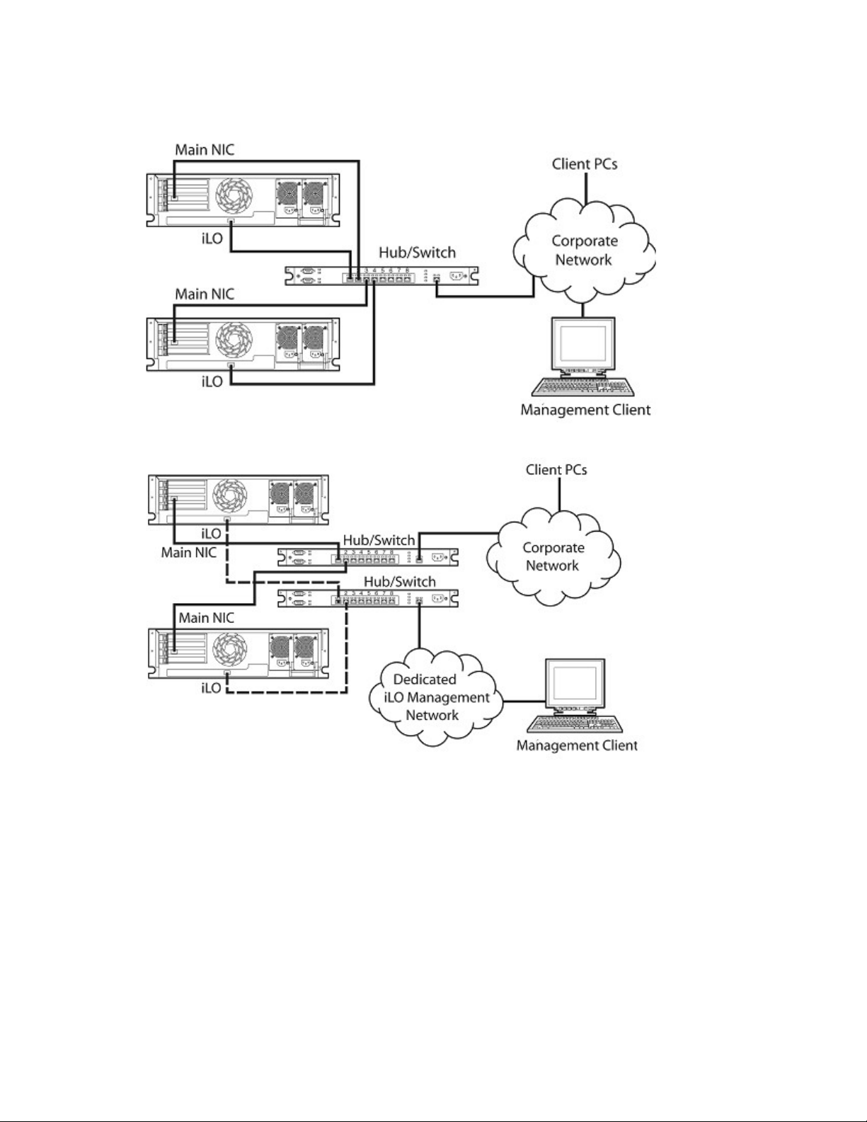
Network connection overview
There are three general network connection scenarios. iLO can be connected on:
• A corporate network with both ports connected to the corporate network. In this configuration, the
server has two network ports (one server NIC, and one iLO NIC) connected to a corporate network.
This connection enables access to iLO from anywhere on the network. On a corporate network,
however, network traffic can hinder iLO performance.
A corporate network configuration reduces the amount of networking hardware and infrastructure
required to support iLO because iLO uses existing DNS and DHCP servers and routers.
• A dedicated management network with the iLO port on a separate network. A separate network
improves performance and security, and provides redundant access to the server when a hardware
failure occurs on the corporate network. In this configuration, iLO cannot be accessed directly from
the corporate network.
A separate network increases the security of the management network because you can physically
control which workstations are connected to the network.
• An iLO Shared Network Port using the server's NIC instead of the dedicated iLO management NIC
for server management. This configuration simplifies the network and reduces total network cost.
Fewer cables, hubs, and switches are needed because both regular and iLO network traffic comes
through the system NIC.
The main disadvantage of using the iLO Shared Network Port for iLO server management is the lack
of speed compared to the dedicated iLO management NIC. As a result, not all iLO management
features are available through the iLO Shared Network Port configuration.
Connect to the network
Typically iLO is connected to the network in one of two ways. iLO can be connected through a:
Configuring iLO 16
Page 17
• Corporate network where both ports are connected to the corporate network. In this configuration,
the server has two network ports (one server NIC, and one iLO NIC) connected to a corporate
network.
• Dedicated management network where the iLO port is on a separate network.
Configure the IP address
This step is necessary only if you are using a static IP address. When using dynamic IP addressing, your
DHCP server will automatically assign an IP address for iLO. HP recommends using DNS or DHCP with
iLO to simplify installation
To configure a static IP address, use the iLO RBSU with the following procedure to disable DNS and
DHCP and configure the IP address and the subnet mask:
1. Restart or power up the server.
2. Press the F8 key when prompted during POST. The iLO RBSU runs.
3. Select Network>DNS/DHCP, press the Enter key, and then select DHCP Enable. Press the spacebar to
turn off DHCP. Be sure that DHCP Enable is set to Off, and save the changes.
Configuring iLO 17
Page 18

4. Select Network>NIC>TCP/IP, press the Enter key, and enter the appropriate information in the IP
Address, Subnet Mask, and Gateway IP Address fields.
5. Save the changes.
6. Exit iLO RBSU. The changes take effect when you exit iLO RBSU.
Installing iLO device drivers
The SmartStart Firmware Maintenance CD contains all of the necessary support for your server, or you
can download all the necessary iLO support drivers from the HP website
(http://www.hp.com/servers/lights-out
To download the drivers:
1. Click the iLO graphic.
2. Select Software and Drivers.
The iLO Management Interface Driver allows system software like SNMP Insight Agents and the Terminal
Services Pass-Through service to communicate with iLO.
Microsoft Windows NT, Windows 2000, and Windows Server 2003 Driver Support
The device drivers that support the iLO are part of the PSP that is located on the HP website
(http://www.hp.com/support
the Windows® documentation and the latest Windows® Service Pack.
) or on the SmartStart CD. Before you install the Windows® drivers, obtain
).
iLO pre-requisite files for Microsoft®
The CPQCIDRV.SYS file provides the iLO Management Interface Driver support.
The CPQASM2.SYS, SYSMGMT.SYS, SYSDOWN.SYS files provide the iLO Advanced Server
Management Controller Driver support.
Installing or updating the iLO drivers for Microsoft®
The PSP for Microsoft® Windows® products includes an installer that analyzes system requirements and
installs all drivers.
The PSP is available on the HP website (http://www.hp.com/support
NOTE: If you are updating the iLO drivers, be sure that the iLO is running the latest version of
the iLO firmware. The latest version can be obtained as a Smart Component from the HP
website (http://www.hp.com/servers/lights-out
To install the drivers in the PSP, download the PSP from the HP website (http://www.hp.com/support),
run the SETUP.EXE file included in the download, and follow the installation instructions. For additional
information about the PSP installation, read the text file included in the PSP download.
).
) or on the SmartStart CD.
Configuring iLO 18
Page 19

Novell NetWare Server Driver Support
The device drivers required to support iLO are part of the PSP that is located on the SmartStart CD and the
HP website (http://www.hp.com/support
iLO pre-requisite files for NetWare
The CPQHLTH.NLM file provides the Health Driver for NetWare.
).
The CPQCI.NLM file provides the iLO Management Interface Driver support.
Installing or updating iLO drivers for NetWare
The PSP for Novell NetWare includes an installer that analyzes system requirements and installs all
drivers. The PSP is available on the HP website (http://www.hp.com/support
) and on the SmartStart CD.
When updating iLO drivers, be sure iLO is running the latest version of the iLO firmware. The latest
version can be obtained as a Smart Component from the HP website (http://www.hp.com/servers/lights-
out).
To install the drivers, download the PSP from the HP website (http://www.hp.com/support
server. After the PSP has been downloaded, follow the NetWare component installation instructions to
complete the installation. For additional information about the PSP installation, read the text file included
in the PSP download.
When using NetWare 6.X, a RAGE-XL video driver is provided by the operating system and should be
used for best results.
Red Hat Linux and SuSE Linux server driver support
The device drivers required to support iLO for Red Hat Linux and SuSE Linux are located on the SmartStart
CD, Management CD, or on the HP website (http://www.hp.com/support
).
) to a NetWare
iLO pre-requisite files for Red Hat and SuSE Linux files
You can download the PSP files containing the iLO driver, the foundation agents, and health agents from
the HP website (http://www.hp.com/support
). The instructions on how to install or update the iLO driver
are available on the website. The HP Management Agents for Linux are:
• ASM package (hpasm) which combines the health driver, IML viewer, foundation agents, health
agent, and standard equipment agent into one package.
• RSM package (hprsm) which combines the RIB driver, rack daemon, RIB agent, and rack agent into
one package.
Configuring Linux font size
To change the font size:
1. Open the KDE Control Center panel and set the fonts.
2. Start Mozilla Firefox, and configure the fonts using the Fonts—Control Center. Set the minimum font
size to 12.
Configuring iLO 19
Page 20

Installing or updating iLO Linux and SUSE drivers
If necessary, uninstall earlier agents. To uninstall earlier agents, execute the following:
• rpm -e cmanic
• rpm -e hprssm
• rpm -e hpasm
To load the health and iLO driver packages use the following commands :
rpm –ivh hpasm-d.vv.v-pp.Linux_version.i386.rpm
rpm –ivh hprsm-d.vv.v-pp.Linux_version.i386.rpm
where: d is the Linux distribution and version and
vv.v-pp are version numbers.
For additional information, refer to the Software and Drivers website (http://www.hp.com/support
To remove the health and iLO drivers, use the following commands:
rpm –e hprsm
rpm –e hpasm
For additional information, refer to the Software and Drivers website (http://www.hp.com/support
Enabling advanced iLO functionality
The Licensing page enables you to view the current license status and enter a key to activate iLO license
features. The iLO version number and current license information appear in this section. If a license is
installed, the license number appears. Evaluation licenses are also shown. To install a license, see
"Activating iLO licensed features using a browser (on page 22)" to install a license.
You must use a license key to activate certain iLO features. Optional licenses activate features that are not
bundled with an unlicensed system.
iLO Select license enables access to the following iLO features in addition to iLO standard features:
• Directory-enabled authentication and authorization ("Directory-enabled remote management" on
page 134)
• Power regulator for ProLiant (on page 84)
• Scripted virtual media (on page 86)
).
).
• Applet virtual media (on page 86) (including Virtual Floppy and Virtual CD)
• Two-factor authentication ("Two-Factor Authentication Settings" on page 33)
In addition to iLO Standard and Select features, the iLO Advanced Pack enables access to the following
features in addition to iLO Standard and Select features:
• Graphical remote console (on page 71)
• Terminal Services pass-through option (on page 36)
Advanced features are enabled by licensing the optional iLO Advanced Pack. The iLO Advanced Pack
contains an activation key that you must enter to enable advanced features. Advanced features can be
evaluated using an evaluation key.
Configuring iLO 20
Page 21

A free 60-day evaluation license is available for download on the HP website
(http://h10018.www1.hp.com/wwsolutions/ilo/iloeval.html
accesses iLO Advanced features. You can only install one evaluation license per iLO. After the evaluation
period, an iLO Advanced license is required to continue using the advanced features. iLO Advanced
features automatically deactivate when the evaluation license key expires.
Licensing
License keys activate optional iLO features not bundled with an unlicensed system. For additional
information, see the HP website
(http://h18004.www1.hp.com/products/servers/proliantessentials/valuepack/licensing.html
An asterisk (*) indicates that a feature is not supported on all systems.
• iLO Standard (unlicensed):
o Virtual power and reset control
o Remote serial console through POST only
o Event logs
o UID light*
o DMTF SMASH CLP
). The evaluation license activates and
).
o RIBCL/XML scripting
o Browser access
o SSH access
o Shared network port*
o Serial access*
• iLO Select:
o Directory integration
o Power Regulator
o Scripted virtual media
o Remote Windows® Kernel debugging capability
o Applet-based virtual media
o Two-factor authentication
• iLO Advanced:
o Directory integration
o Power Regulator monitoring
o Scripted virtual media
o Kernel debugging
o Applet-based virtual media
o Two-factor authentication
o Terminal Services integration
o Remote Console
In addition to standard iLO single-server licenses, two other licensing options are available:
Configuring iLO 21
Page 22

• The Flexible Quantity License Kit allows customers to purchase a single software package, one copy
of the documentation, and a single license key to activate the exact number of licenses requested.
• The Activation Key Agreement is available for customers planning a volume purchase of ProLiant
Essentials and Insight Control software, typically in conjunction with new ProLiant servers that is
acquired on a regular basis.
Activating iLO licensed features using a browser
1. Log in to iLO through a supported browser.
2. Select the Administration tab.
3. Click Licensing to display the iLO Licensing activation screen.
4. Enter the activation key in the space provided.
5. Click Install. The EULA confirmation appears. The EULA details are available on the HP website
(http://www.hp.com/servers/lights-out
6. Click OK.
The advanced features of iLO are now enabled.
Administration
The options available in the Administration tab enable you to manage user settings, SNMP alerting
through integration with Systems Insight Manager, security settings, licensing, certificate administration,
directory settings, and network environment settings. This section also provides a firmware upgrade
option that enables you to keep iLO current.
) and with the Advanced Pack License kit.
Configuring iLO 22
Page 23

User administration
User Administration enables you to manage the user accounts stored locally in the secure iLO memory.
Directory user accounts are managed using MMC or ConsoleOne snap-ins. Using the User Administration
screen, you can add a new user, view or modify an existing user's settings, or delete a user.
iLO supports up to 12 users with customizable access rights, login names and advanced password
encryption. Individual user's abilities are controlled by privileges. Each user can have privileges customtailored to their access requirements.
To support more than 12 users, iLO Advanced enables integration with virtually unlimited directory-based
user accounts.
Adding a new user
IMPORTANT: Only users with the Administer User Accounts privilege can manage other users
on iLO.
You can assign a different access privilege to each user. Each user can have a unique set of privileges,
designed for the tasks that the user must perform. Access to critical functions, such as Remote Console,
Managing Users, Virtual Power button, and other features can be denied.
To add a new user to iLO:
1. Log on to iLO using an account that has the Administer User Accounts privilege. Click
Administration.
2. Click User Administration. A screen similar to the one shown appears.
3. Click Add.
4. Complete the fields with the necessary information for the user being added.
5. When the user profile is complete, click Save User Information to return to the User Administration
screen. To clear the user profile form while entering a new user, click Restore User Information.
Configuring iLO 23
Page 24

Viewing or modifying an existing user's settings
IMPORTANT: Only users with the Administer User Accounts privilege can manage other users
on iLO. All users can change their own password using the View/Modify User feature.
1. Log on to iLO using an account that has the Administer User Accounts privilege. Click
Administration.
2. Click User Administration, and select from the list the name of the user whose information you want
to change.
3. Click View/Modify.
4. Change the user information in the fields that require modification. After changing the fields, click
Save User Information to return to the User Administration screen. To recover the user's original
information, click Restore User Information. All changes made to the profile will be discarded.
To modify user certificate information, refer to the "Two-factor authentication user certificates (on page
Deleting a user
61)" section.
IMPORTANT: Only users with the Administer User Accounts privilege can manage other users
on iLO.
To delete an existing user's information:
1. Log on to iLO using an account that has the Administer User Accounts privilege. Click
Administration.
2. Click User Administration and select from the list the name of the user whose information you want to
change.
3. Click Delete User. A pop-up window is displayed asking, Are you sure you want to delete
the selected user? Click OK.
Global settings
The Global Settings option enables you to view and modify iLO security settings. With the Global Settings
option you can configure the Remote Console time-out and iLO ports to be used for the iLO Web Server,
Remote Console, and Virtual Media. These settings are applied globally, regardless of individual user
settings.
Configuring iLO 24
Page 25

You must have the Configure iLO Settings privilege to change these settings. Users that do not have the
Configure iLO Settings privilege can only view assigned settings. To manage this privilege, use the
Configure Local Device Settings in the directory administration snap-ins for directory users.
The Global Settings option enables you to define the following functions:
• Idle Connection Timeout (minutes)
• Enable Lights-Out Functionality
• Passthrough Configuration
• Enable iLO ROM-Based Setup Utility
• Require Login for iLO RBSU
• Show iLO during POST
• Remote Console Port Configuration
• Remote Console Data Encryption
• Enable Remote Console Acquire
• SSL Encryption Strength
• Current Cipher
• Web Server Non-SSL Port
• Web Server SSL Port
• Virtual Media Port
• Remote Console Port
• Terminal Services Port
• Secure Shell (SSH) Port
Configuring iLO 25
Page 26

• Secure Shell (SSH) Status
• Serial Command Line Interface Status
• Serial Command Line Interface Speed (bits/second)
• Minimum Password Length
• Remote Keyboard Model
To change iLO global settings:
1. Log in to iLO using an account that has the Configure iLO Settings privilege. Click Administration.
2. Click Global Settings.
3. Change global settings by entering your selections.
4. After completing any parameter changes, click Apply to save the changes.
For more information, see the HP Integrated Lights-Out Management Processor Scripting and Command
Line Resource Guide.
Network settings
The Network Settings option enables you to view and modify the NIC IP address, subnet mask, and other
TCP/IP-related settings. From the Network Settings screen, you can enable or disable DHCP and, for
servers not using DHCP, you can configure a static IP address.
You must have the Configure iLO Settings privilege to change these settings. Users that do not have the
Configure iLO Settings privilege can only view the assigned settings.
To change network settings for iLO:
1. Log in to iLO using an account that has the Configure iLO Settings privilege. Click Administration.
2. Click Network Settings.
3. Change the network settings as needed.
Configuring iLO 26
Page 27

4. After completing any parameter changes, click Apply to complete the changes.
When you click Apply, iLO restarts, and your browser connection to iLO terminates. To re-establish a
connection, wait 60 seconds before launching another web browser session and logging in.
For more information, see the HP Integrated Lights-Out Scripting and Command Line Resource Guide.
iLO diagnostic port configuration parameters
The iLO Diagnostic Port on the front of ProLiant BL p-Class servers enables you to access and troubleshoot
server issues by using a diagnostic cable. The iLO Diagnostic Port uses a static IP address. It does not use
DHCP to obtain an IP address, register with WINS or dynamic DNS, or use a gateway. The diagnostic
port cable should not be left plugged in without an active network connection, as it will cause degraded
network performance on the standard iLO network port.
In Network Settings, you can configure specific diagnostic port information. For more information on
using the diagnostic port and the diagnostic cable, refer to the Setup and Installation Guide for the blade
server.
The following are the fields that can be configured for the diagnostic port:
• Enable NIC
If Enable NIC is set to Yes, the diagnostic port is enabled.
• Transceiver Speed Autoselect
• Speed
• Duplex
• IP Address
Use this parameter to assign a static IP address to iLO on your network. By default, the IP address is
assigned by DHCP. By default, the IP address is 192.168.1.1 for all iLO Diagnostic Ports.
Configuring iLO 27
Page 28

• Subnet Mask
o Use the subnet mask parameter to assign the subnet mask for the iLO Diagnostic Port. By default,
the subnet mask is 255.255.255.0 for all iLO Diagnostic Ports.
o The use of the diagnostic port is automatically sensed when an active network cable is plugged
in to it. When switching between the diagnostic and back ports, you must allow 90 seconds for
the network switchover to complete before attempting connection through the Web browser.
NOTE: The diagnostic port will not switch over if an active Remote Console session or a
firmware update is in progress.
Recovering from a failed iLO firmware update
In the event that an iLO firmware update has failed, there are various recovery options. For all of these
options, you need a current firmware image. HP does not recommended downgrading iLO firmware, and
the version you have could be corrupt.
1. Download the latest iLO firmware. iLO downloads are available on the HP website
(http://h18004.www1.hp.com/support/files/lights-out/us/index.html
2. Determine if the update failed.
a. Can you ping iLO?
).
b. Can you log in?
c. Does the iLO Option ROM prompt appear during host POST?
d. Are the iLO status LEDs strobing in a regular pattern? Examine the iLO status LEDs inside the
server to see if they are strobing in a regular pattern from LED 8, 7, 6, 5, 4, 3, 2, 1. If the iLO
LED pattern is visible, proceed to step 4.
3. Attempt to re-flash over the network.
You might be able to initiate a firmware update using RIBCL or a browser.
If network flash failed, try the on-line flash component. Components are available for both
Windowst® and Linux.
4. If the on-line flash component failed, try the ROMPAQ diskette.
a. Build the ROMPAQ diskettes and boot the host using disk 1.
b. You might need to set the iLO Security Override Switch for ROMPAQ to succeed. Restore the
Security Override Switch after the flash process is complete.
SNMP/Insight Manager settings
The SNMP/Insight Manager Settings option enables you to configure SNMP alerts, generate a test alert,
Enabling SNMP alerts
and configure integration with Systems Insight Manager.
iLO supports up to three IP addresses to receive SNMP alerts. Typically, the addresses used are the same
as the IP address of the Systems Insight Manager server console.
You must have the Configure iLO Settings privilege to change these alert settings. Users that do not have
the Configure iLO Settings privilege can only view the assigned settings.
The following alert options are available in the SNMP/Insight Manager Settings screen:
Configuring iLO 28
Page 29

• Enable iLO SNMP Alerts
• Forward Insight Manager Agent SNMP Alerts
• Enable SNMP Pass-thru
• Enable p-Class Alert Fowarding (displayed on p-Class servers only)
For more information, see the HP Integrated Lights-Out Management Processor Scripting and Command
Line Resource Guide.
To configure alerts:
1. Log in to iLO using an account that has the Configure iLO Settings privilege.
2. Select SNMP/Insight Manager Settings in the Administration tab.
3. Enter up to three IP addresses to receive SNMP alerts.
4. Select the alert options you want iLO to support.
5. Click Apply Settings.
Generating test alerts
Test alerts are generated by means of the SNMP/Insight Manager Settings in the Administration section of
the iLO navigation frame. These alerts include an Insight Manager SNMP trap and are used to verify the
network connectivity of iLO in Systems Insight Manager. Only users with the Configure iLO Settings
privilege can send test alerts.
Click Apply Settings to save any changes made to SNMP Alert Destinations before sending a test alert.
To send a test alert:
1. Select SNMP/Insight Manager Settings in the Administration tab.
2. Click Send Test Alert to generate a test alert and send it to the TCP/IP addresses saved in the SNMP
Alert Destinations fields.
Configuring iLO 29
Page 30
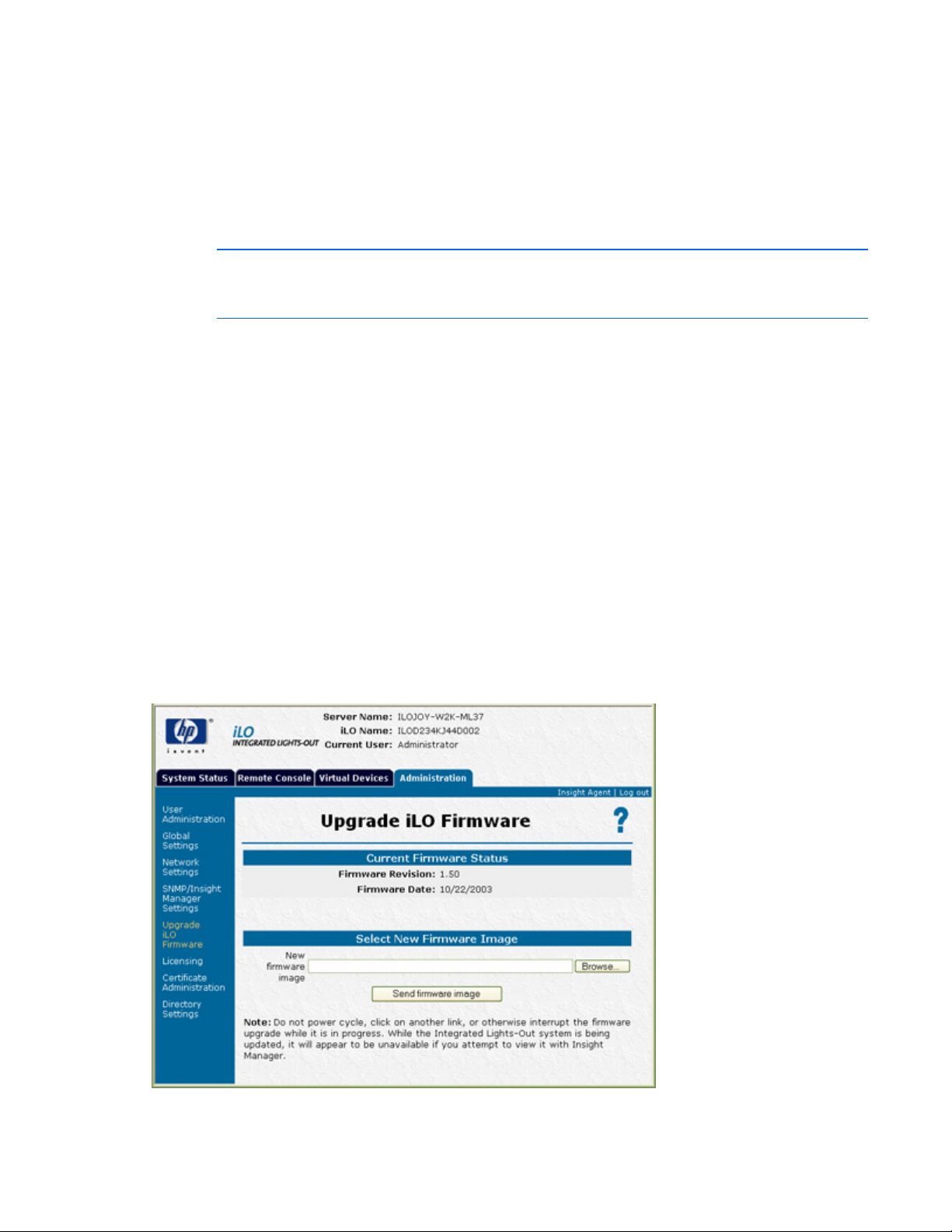
3. After generating the alert, a confirmation screen is displayed.
4. Check the Systems Insight Manager console for receipt of the trap.
Configure Insight Manager integration
iLO enables you to configure the URL (DNS name or IP address) of the Insight Manager Web Agents
running on the host server. You can also configure the level of data returned with Systems Insight
Manager identification information.
NOTE: The expected entry in the Insight Manager Web Agent URL field is the IP address or the
DNS name only. The protocol (for example, "http://") and a port ID (for example, ":2301")
The link to the Insight Web Agents is found on the blue header bar, next to the Log out link.
should not be entered.
Directory Settings
The Directory Settings screen enables you to configure and test your directory services. For additional
information on directories, refer to "Directory services (on page 104)." For additional information on
directory configuration parameters, refer to "Configuring Directory Settings (on page 64)."
Upgrade iLO firmware
Firmware upgrades enhance the functionality of iLO. The firmware upgrade can be done from any
network client using a supported Web browser. Only users with the Update iLO Firmware privilege can
upgrade the iLO firmware. The most recent firmware for iLO is available on the HP website.
To upgrade the iLO firmware using a supported Web browser:
1. Log on to iLO using an account that has the Configure iLO Settings privilege.
2. Click Upgrade iLO Firmware in the Administration tab.
3. Enter the file name in the New firmware image field or browse for the file.
Configuring iLO 30
Page 31

4. Click Send firmware image.
5. The firmware upgrade takes a couple of minutes. A progress bar displays the progress of the
firmware upgrade.
Do not interrupt an Upgrade iLO Firmware session that is in progress. If the upgrade process is
interrupted, refer to the "Inability to upgrade iLO firmware (on page 181)" section.
The iLO system automatically resets at the end of a successful firmware upgrade. The host operating
system and server are not affected by the iLO system being reset.
If the firmware upgrade was interrupted or failed, immediately attempt the upgrade again. Do not reset
the iLO system before reattempting a firmware upgrade. iLO provides an FTP-based firmware upgrade
disaster recovery ("Inability to upgrade iLO firmware" on page 181) if a firmware upgrade is interrupted
or failed.
NOTE: For systems with diskette drives, you can also update the iLO firmware using ROMPaq
diskettes. HP does not recommend updating iLO firmware using the Virtual Media floppy
diskette.
Certificate administration
The Certificate Information screen displays the information associated with the stored certificate.
Information is encoded in the certificate by the CA, and is extracted by iLO for display.
• Issued To is the entity to whom the certificate was issued.
• Issued By is the CA that issued the certificate.
• Valid From is the date from which the certificate is valid.
• Valid Until is the date that the certificate will expire.
• Serial Number is the serial number assigned to the certificate by the CA.
The Importing a Certificate page displays information about how to import a certificate. For more
information about importing certificates, see "Certificates (on page 54)" and the HP Integrated Lights-Out
Management Processor Scripting and Command Line Resource Guide.
Configuring iLO 31
Page 32

SSH Key Administration
This page displays the owner of each authorized SSH key. Any key can be selected and viewed in detail
or deleted by clicking View Selected Key or Delete Selected Key. Up to four keys may be authorized.
Multiple keys can belong to one user.
To authorize a new key:
1. Click Browse and locate the key file.
The public key file path must be submitted to iLO. The key file should contain the user name after the
end of the key. iLO will associate each key with a local user account. If the local account does not
exist or if it is deleted, the key will be invalid (the key will not be listed here if the local account does
not exist.) Alternatively, you can authorize SSH keys for an HP SIM server by running the
mxagentconfig tool from the HP SIM server, specifying the address and user credentials for iLO.
Refer to HP SIM documentation for more details.
2. Click Authorize Key.
Configuring iLO 32
Page 33

Two-Factor Authentication Settings
This page displays the configuration of two-factor authentication settings and the trusted CA certificate
information. It also provides a method of changing the configuration and importing or deleting a trusted
CA certificate.
The Enforce Two-Factor Authentication setting controls whether two-factor authentication will be used for
user authentication during login. Selecting Yes for this setting will require two-factor authentication. The
No value will disable this feature and allow login with user name and password only. iLO will not allow
this setting to be changed to Yes if a trusted CA certificate has not been configured. Changing this setting
causes iLO to reset for the change to take effect. To provide the necessary security, the following
configuration changes will also be made when two-factor authentication is enabled:
• Remote Console Data Encryption: Yes (Disables telnet access)
• Enable Secure Shell (SSH) Access: No
• Serial Command Line Interface Status: Disabled
If telnet, SSH, or Serial CLI access is required, re-enable these settings after two-factor authentication is
enabled. However, because these access methods do not provide a means of two-factor authentication,
only a single factor is required to access iLO with telnet, SSH or Serial CLI.
When two-factor authentication is enabled, access with the CPQLOCFG utiltiy is disabled, because
CPQLOCFG does not supply all authentication requirements. However, the HPONCFG utility is functional,
because administrator privileges on the host system are required to execute this utility.
The Check for Certificate Revocation setting controls whether iLO uses the certificate CRL distribution
points attribute to download the latest CRL and check for revocation of the client certificate. If the client
Configuring iLO 33
Page 34

certificate is contained in the CRL or if the CRL cannot be downloaded for any reason, access is denied.
The CRL distribution point must be available and accessible to iLO when Check Certificate Revocation is
set to Yes.
The Certificate Owner Field setting specifies which attribute of the client certificate to use when
authenticating with the directory. If SAN is specified, iLO will extract the User Principle Name from the
Subject Alternative Name attribute and the use User Principle Name when authenticating with the
directory, for example, username@domain.extension. If Subject is specified, iLO will derive the user's
distinguished name from the subject name attribute. For example, if the subject name is
/DC=com/DC=domain/OU=organization/CN=user, iLO will derive:
CN=user,OU=organization,DC=domain,DC=com.
The Certificate Owner Field setting is only used if directory authentication is enabled. Configuration of this
setting depends on the version of directory support being used, the directory configuration, and the
certificate issuing policy of your organization.
A trusted CA certificate is required for two-factor authentication to function. iLO will not allow the Enforce
Two-Factor Authentication setting to be set to Yes if a trusted CA certificate has not been configured. Also,
a client certificate must be mapped to a local user account if local user accounts are being used. If the
iLO is using directory authentication, client certificate mapping to local user accounts is optional.
To change two-factor authentication settings for iLO:
1. Log on to iLO using an account that has the Configure iLO Settings privilege. Click Administration.
2. Click Two-Factor Authentication Settings.
3. Change the settings as needed by entering your selections in the fields.
4. After completing any parameter changes, click Apply to save the changes.
Hot-plug keyboard
Hot-plug keyboard functionality was implemented for all servers with iLO. The hot-plug keyboard feature
supports connecting a local keyboard to the server while the server is in a powered-on state. It is not
necessary to power cycle the server to get local keyboard functionality after hot-plugging a keyboard. If a
keyboard is connected to the server after the operating system has booted, the hot-plugged keyboard is
Keyboard definitions
fully functional. The keyboard can be hot-plugged multiple times after the operating system has booted.
• Local keyboard—A keyboard physically connected to the PS2 connector on the server.
• Remote Console keyboard—The keyboard used during a Remote Console session.
• Hot-plug keyboard functionality—A fully-functioning local keyboard after hot-plugging it to a server.
• Hot-plugging a keyboard—Connecting a local keyboard to the keyboard PS2 connector on the
server while the server is in a powered-on state.
• Hot-unplugging a keyboard—Disconnecting a local keyboard from the server while the server is in a
powered on state.
Hot-plug keyboard recommended usage
For best results, follow these guidelines:
Configuring iLO 34
Page 35

• Only hot-plug a local keyboard after the operating system has booted.
• Do not hot-unplug the local keyboard before the operating system has booted. Hot-plugging or hot-
unplugging of the local keyboard before the operating system boots can lead to unpredictable
results.
WARNING: Do not change iLO network settings or port assignments, reset iLO, upgrade iLO
firmware, or otherwise make iLO unavailable while powering on the server or booting the
operating system without a local keyboard connected. Perform these actions before powering
on the server or after the operating system has booted. If performing these actions before
powering on the server, wait 30 seconds until applying power.
Failure to follow the preceding guidelines can result in loss of local and Remote Console keyboard
functionality.
Hot-plug keyboard troubleshooting
If the hot-plug keyboard is unavailable or locks up, review the following to correct the problem. For best
results, follow the guidelines in "Hot-plug keyboard recommended usage (on page 34)."
• If a Remote Console session is active on the server, the local keyboard will not be functional after
hot-plugging it. This configuration is by design, for security purposes.
• If iLO is unavailable from power-on through operating system boot and a local keyboard is not
present, Remote Console keyboard functionality might not function when iLO becomes available
again, depending on the operating system. iLO can become unavailable for various reasons,
including firmware upgrade, network settings change, or reassignment of ports. It might be
necessary to power cycle the system to regain Remote Console keyboard functionality.
• If iLO is unavailable from power-on through operating system boot and a local keyboard is hot-
plugged after operating system boot, the Remote Console and local keyboard might not function
when iLO becomes available again, depending on the operating system. iLO can become
unavailable for various reasons, including a firmware upgrade, network settings change, or
reassignment of ports. It might be necessary to power cycle the system to regain Remote Console
and local keyboard functionality.
• If iLO should become so busy that it is unable to respond in a timely fashion to keyboard commands
sent by operating system while the operating system is loading and a local keyboard is not present,
the operating system will assume that no keyboard is connected. This situation is unlikely but can
theoretically occur any time iLO becomes extremely busy. An example of this condition is when iLO
experiences a Denial of Service attack over its NIC. In this case, if a keyboard is hot-plugged after
the operating system is loaded, local and Remote Console keyboard functionality might not function,
depending on the operating system. It might be necessary to power cycle the system to
regain Remote Console keyboard functionality.
• If a local keyboard is hot-unplugged after the operating system boots with caps-lock, num-lock, or
scroll lock on and then is hot-plugged, the LED indicators on the local keyboard will not reflect the
current state of the keyboard. Press the lock key for the desired function until the correct LED
indicator state is reached.
• If the local keyboard locks up when hot-plugged, unplug the keyboard and plug it in again.
Configuring iLO 35
Page 36

Terminal Services pass-through option
Terminal Services is provided by the Microsoft® Windows® operating systems. The iLO Terminal Services
pass-through option provides a connection between the Terminal Services server on the host system and
the Terminal Services client on the client system. When the Terminal Services pass-through option is
enabled, iLO firmware sets up a socket, listening by default on port 3389. All data received from the
Terminal Services on this port is forwarded to the server and all data it receives from the server is
forwarded back to the socket. The firmware assumes anything received on this port is in an RDP packet.
RDP packets are exchanged between the iLO firmware and the server's Terminal Services (RDP) server
through the localhost address on the server. A service is provided to facilitate communications between
the iLO firmware and the RDP server, such that the RDP server believes that an external RDP connection
has been established. For more information on RDP service, refer to the "Windows® RDP Pass-Through
service (on page 37)" section.
A Terminal Services session provides a performance-enhanced view of the host system console. When the
operating system is unavailable (or the Terminal Services server or client is unavailable), the traditional
iLO remote console provides the view of the host system console. For more information on Remote
Console and Terminal Services, refer to the "Remote Console and Terminal Services clients (on page 39)"
section.
To configure the Terminal Services pass-through option, refer to "Terminal Services Client requirements (on
page 36)" and "Terminal Services Pass Through installation ("Terminal Services Pass-Through installation"
on page 37)."
Terminal Services Client requirements
The Terminal Services client is available on Microsoft® Windows® client machines running:
• Windows® 2000
Microsoft® Windows® 2000 servers require the installation of Microsoft® .NET Framework to
support the use of Terminal Services. After .NET Framework is installed, the Terminal Services client
must be installed from diskettes created by the Terminal Services server. Consult your Windows®
operating guides or help files for instructions. When installing the Terminal Services client on
Windows® 2000, use the default installation location. The Terminal Services client in Windows®
2000 generates a dialog box asking for which target Terminal Services server to use.
• Windows® Server 2003
On Windows® Server 2003 servers, the Terminal Services client and RDP connection is built in. The
client is an integral part of the operating system and is activated using Remote Desktop sharing. To
activate desktop sharing allow, select My Computer>Properties>Remote>Remote Desktop. The
Terminal Services client in Windows® Server 2003 provides command line options and seamless
launches from the Remote Console applet.
• Windows® XP
On Windows® XP servers, the Terminal Services client and RDP connection is built in. The client is
an integral part of the operating system and is executed by selecting
Start>Programs>Accessories>Communications>Remote Desktop. The Terminal Services client in
Windows® XP provides command line options and seamless launches from the Remote Console
applet.
Configuring iLO 36
Page 37

Windows® RDP Pass-Through service
To use the iLO Terminal Services Pass-Through feature, a service must be installed on the host system. This
service will show the name of iLO Proxy in the host's list of available services. The service utilizes the
Microsoft® .NET framework's security and reliability. After the service has started, the service polls the
iLO to find out if a an RDP connection with the client has been established. If an RDP connection with the
client has been established, it then establishes a TCP connection with localhost and begins exchanging
packets. The port used to communicate with localhost is read from the Windows® registry at
HKLM\SYSTEM\CurrentControlSet\Control\TerminalServer\Wds\rdpwd\Tds\tcp\P
ortNumber
This is typically port 3389.
Terminal Services Pass-Through installation
• Microsoft® Windows® 2000 and Windows® 2003
Microsoft® Windows® 2000 servers require Microsoft® .NET Framework to support the use of
Terminal Services. The Terminal Services pass-through service and the iLO Management Interface
Driver for Windows® 2000 and Windows® Server 2003 must be installed on the server that has
the iLO. The service and iLO driver are available as Smart Components on the HP website and on
the HP SmartStart CD. They are also part of the ProLiant Support Pack for Microsoft® Windows®
Server 2003 and Microsoft® Windows®.
a. Install the iLO Management Interface driver.
b. Install the service. To install the service, launch the component installer and follow the directions
in the installation wizard.
If the service is already installed, then it must be manually restarted or the server rebooted when
the driver is installed.
c. Install or activate the Terminal Services client.
Microsoft® Windows® 2000 servers require the installation of Microsoft® .NET Framework to
support the use of Terminal Services. After .NET Framework is installed, the Terminal Services
client must be installed from diskettes created by the Terminal Services server or by downloading
the client from the Microsoft® website and installed through the Control Panel using Add or
Remove Programs. Consult your Windows® operating guides or help files for instructions. When
installing the Terminal Services client on Windows® 2000, use the default installation location.
On Windows® Server 2003, you can activate Remote Desktop sharing by selecting the Remote
tab under My Computer and Properties.
If the iLO installation is complete and if Terminal Services pass-through is set to automatic, then
Terminal Services launches when the installation is complete.
• Microsoft® Windows® XP
On Windows® XP servers, Remote Desktop Connection is built in and has no other installation
requirements.
Errors during installation and during execution of the pass-through service will be logged in the server's
Application Event Log. The pass-through service may be removed using Add or Remove Programs in the
Control Panel.
Configuring iLO 37
Page 38

Windows® 2000 Terminal Services port change
If the Terminal Services port is changed, Windows® 2000 client must manually configure the Terminal
Services Client Connection Manager.
1. Start the Terminal Services Client Connection Manager, and create a new connection to the terminal
server.
2. Highlight the icon created, and select File>Export. Rename the file with a .cns extension. For
example: myilo.cns.
3. Edit the myilo.cns file by looking for the line Server Port=3389. Replace 3389 with your new port
number and save the file.
4. From the Client Connection Manager, highlight the New Connection icon, and click File>Import.
5. Double-click the newly created icon to launch terminal server and connect to the new port.
Enabling the Terminal Services Pass-Through option
By default, the Terminal Services pass-through feature is disabled and must be enabled in Global Settings.
Until the Terminal Services pass-through feature is enabled, the Remote Console has the Terminal Services
button deactivated, and the console session error message Remote Session already in use by
another user is misleading.
Use of the Terminal Services pass-through feature requires installation of the latest Lights-Out Management
Interface Driver and Terminal Services pass-through Service for Microsoft® Windows® on the server. The
interface driver must be installed before installing the service.
When the Terminal Services pass-through option is set to Enabled or Automatic on the Global Settings
page and the Terminal Services Client is installed on the Windows® client (installs by default on
Windows® XP), the Terminal Services button is enabled. When the Terminal Services button is clicked,
the applet tries to launch the Terminal Services, even if the server is not running a Windows® operating
system.
You must comply with Microsoft® license requirements which are the same as connecting through the
server's NIC. For instance, when set for administrative access, Terminal Services does not allow more
Terminal Services Pass-Through status
than two connections, regardless of whether the connections are through the server's NIC or iLO or both.
The iLO Status page displays the status of the Terminal Services pass-through feature, as follows:
• Server software not detected
• Available for use
• In use
The UID light flashes whenever a Terminal Services connection is active through the iLO. It flashes at the
same frequency and duty cycle as when the Remote Console is active.
Terminal Services warning message
Terminals Services users operating on Windows® 2003 Server might notice the following when using the
Terminal Services pass-through feature of iLO. If a Terminal Services session is established through iLO
and a second Terminal Services session is established by a Windows® administrator (Console mode), the
first Terminal Services session is disconnected. However, the first Terminal Services session does not
Configuring iLO 38
Page 39

receive the warning message indicating the disconnection until approximately one minute later. During
this one-minute period, the first Terminal Services session is available or active. This is normal behavior,
but it is different than the behavior observed when both Terminal Services sessions are established by
Windows® administrators. In that case, the warning message is received by the first Terminal Services
session immediately.
Terminal Services button display
This version of the iLO firmware does not accurately display through the Terminal Services button whether
the host operating system is enabled for Terminal Services operation. Even if the operating system is not
enabled (for example, the host operating system is Linux, which does not support Terminal Services
operation), the Terminal Services button might not appear inactive and might inaccurately imply that
Terminal Services operation is available.
Remote Console and Terminal Services clients
Using the management network connection to the iLO, an iLO Remote Console session can be used to
display a Terminal Services session to the host. When the iLO Remote Console applet runs, it launches the
Terminal Services client based on user preference. The Sun JVM must be installed to obtain full
functionality of this feature. If the Sun JVM is not installed, then the dual-cursor Remote Console cannot
automatically launch the Terminal Services client.
If Terminal Services pass-through is enabled, and the Terminal Services server is available, switching
between iLO Remote Console and the Terminal Services client will be seamless as the server progresses
from pre-OS environment to OS-running environment, to OS-not available environment. The seamless
operation is available as long as the Terminal Services client is not started before Remote Console is
available. If Remote Console is available, and the Terminal Services client is available, Remote Console
will start the Terminal Services client when appropriate.
When using the Terminal Services pass-through option with Windows® 2000, there is approximately a
one-minute delay after the CTRL-ALT-DEL dialog box appears before the Terminal Services client launches.
On Windows® Server 2003, the delay is about 30 seconds. The 30 second delay represents how long it
takes for the service to connect to the RDP client running on the server. If the server is rebooted from the
Terminal Services client, the Remote Console screen turns grey or black for up to one minute while iLO
determines that the Terminal Services server is no longer available.
If Terminal Services mode is set to Enabled, but you want to use the Remote Console, then the Terminal
Services client should be launched directly from the Terminal Services client menu. Launching directly from
the client menu allows simultaneous use of the Terminal Services client and the Remote Console.
Terminal Services can be disabled or enabled at any time. Changing the Terminal Services configuration
causes the iLO firmware to reset. Resetting the iLO firmware interrupts any open connections to iLO.
When the Terminal Services client is launched by the Remote Console, Remote Console goes into a sleep
mode to avoid consuming CPU bandwidth. Remote Console still listens to the Remote Console default port
23 for any commands from the iLO.
iLO passes-through only one Terminal Services connection at a time. Terminal Services has a limit of two
concurrent sessions.
The Remote Console activates and becomes available if the Remote Console is in sleep mode and the
Terminal Services client is interrupted by any of the following:
• The Terminal Services client is closed by the user.
Configuring iLO 39
Page 40

• The Windows® operating system is shut down.
• The Windows® operating system locks-up.
Terminal Services troubleshooting
If you are experiencing problems with iLO Terminal Services Pass-through, check the following:
1. Verify that Terminal Services is enabled on the host by selecting My
Computer>Properties>Remote>Remote Desktop.
2. Verify that the iLO pass-through configuration is enabled or automatic by checking iLO Global
Settings.
3. Verify whether iLO Advanced functionality is licensed.
4. Verify whether the iLO Management Interface Driver is installed on the host by selecting My
Computer>Properties>Hardware>Device Manager>Multifunction Adapters.
5. Verify if Terminal Services pass-through service and iLO Proxy is installed and running on the host by
selecting Control Panel>Administrative Tools>Services and attempting to restart the service.
6. Determine whether the Application Event Log is full.
The Terminal Services Pass-through service might experience start-up problems when the operating
system Application Event Log is full. To view the event log, select Computer Management>System
Tools>Event Viewer>Application.
7. Verify that the Terminal Services port assignment is correct. Verify that the Terminal Services client,
mstsc.exe is located in \WINDOWS\SYSTEM32.
If not, reconfigure the pass-through configuration to Enabled and manually activate the terminal
services client.
iLO Shared Network Port
The iLO Shared Network Port enables you to choose either the system NIC or the dedicated iLO NIC for
server management. Both regular network traffic and network traffic intended for iLO pass through the
system NIC when this feature is selected. The iLO Shared Network Port is only available on a limited
number of ProLiant servers, as shown in the “iLO Shared Network Port requirements (on page 40)”
section.
Not all iLO management features are available when using the iLO Shared Network Port. Refer to the
“iLO Shared Management Port features and restrictions (on page 41)” section for a list of supported and
iLO Shared Network Port requirements
unsupported iLO management features.
The iLO Shared Network Port feature is only available on servers with hardware that supports this feature.
In addition to the hardware, both the NIC and iLO firmware must support the feature.
ProLiant server Minimum iLO firmware version
DL320G3 1.64
DL360 G4 1.60
DL360 G4 1.64
DL380 G4 1.60
Configuring iLO 40
Page 41

ProLiant server Minimum iLO firmware version
DL385 G1 1.64
DL580 G3 1.64
ML370 G4 1.60
ML570 G3 1.64
When using the iLO Shared Network Port, flashing the iLO firmware through the XML interface will take
approximately 7 minutes to complete.
iLO Shared Management Port features and restrictions
Only the iLO Shared Network Port or the iLO Dedicated Management NIC port can be used for iLO
server management at one time. The iLO Shared Network Port and the iLO Dedicated Management NIC
port cannot operate simultaneously. Enabling the dedicated iLO NIC disables the iLO Shared Network
Port, and enabling the iLO Shared Network Port disables the dedicated iLO NIC.
Disabling the Shared Network Port does not completely disable the system NIC. Regular network traffic
still passes through the system NIC. When the Shared Network Port network traffic is disabled any traffic
going to or originating from iLO is not passed on to iLO through the shared Network Port because the
port is no longer shared with iLO.
The speed of the Shared Network Port is relatively low compared to the dedicated iLO Management Port.
Only a limited number of iLO features are supported through the Shared Network Port. These include:
• Command line interface
• XML scripting
• Virtual Serial Port
• Text based Remote Console
• SNMP protocol
Due to the relatively low performance of the Shared Network Port, certain operations performed over the
Virtual Serial Port connection may perform at less than optimum levels. In particular, display or text editing
operations involving the display of large amounts of data may result in some dropped characters. The loss
of characters affects the display only, and does not affect the data stored on the server.
The iLO Web interface is not supported through the Shared Network Port, including:
• Graphical Remote Console
• Virtual Media
When the Shared Network Port is selected, iLO must be configured through either the iLO RBSU or XML.
Configuration through RBSU requires that the system be rebooted.
Enabling the iLO Shared Network Port feature
The iLO Shared Network Port feature is disabled by default. This feature can be enabled through:
• iLO RBSU
• The iLO Web interface
• XML scripting
Configuring iLO 41
Page 42

When configured for iLO Shared Network Port, iLO's MTU is 320 bytes, and its DHCP request packets
are split into multiple packets (using IP fragmentation). This may be a problem if your DHCP server is on a
different subnet, and your DHCP relay agent (commonly your Layer 3 Ethernet Switch) does not support
forwarding of fragmented DHCP frames. The DHCP server will never receive the DHCP request from iLO,
and iLO will not be able to obtain an IP address. In this situation, you must configure iLO with a static IP
address.
Enabling the iLO Shared Network Port feature through the web interface
1. Connect iLO NIC port 1 to a LAN.
2. Open a browser, and browse to the iLO IP address or DNS name.
3. Select Administration>Network Settings.
4. On the Network Settings page, select Shared Network Port. The Shared Network feature is only
available on supported servers.
5. Click Apply at the bottom of the page.
6. Click Yes in the warning dialog box, and click OK.
After iLO resets, the Shared Network Port feature will be active. Any network traffic going to or
originating from iLO is directed through the system's NIC port 1.
The iLO web interface is no longer available after iLO resets. To restore the use of the web interface, iLO's
Dedicated Management NIC port must be re-enabled. Refer to the "Re-enabling the dedicated iLO
management port (on page 43)" section for more information.
Only the Shared Management NIC Port or the dedicated iLO NIC port is active for server management at
one time. They both cannot be enabled at the same time.
Enabling the iLO Shared Network Port feature through iLO RBSU
1. Connect the server's NIC port 1 to a LAN.
2. When prompted during POST, press the F8 key to enter iLO RBSU.
3. Select Network>NIC>TCP/IP and press the Enter key.
Configuring iLO 42
Page 43

4. In the Network Configuration menu, toggle the Network Interface Adapter Field to Shared Network
Port by pressing the space bar. The Shared Network Port option is only available on supported
servers.
5. Press the F10 key to save the configuration.
6. Select File>Exit, and press the Enter key.
After iLO resets, the Shared Network Port feature will be active. Any network traffic going to or
originating from iLO is directed through the system's NIC port 1.
Re-enabling the dedicated iLO management port
The iLO RBSU or XML scripting (described in the HP Integrated Lights-Out Management Processor
Scripting and Command Line Resource Guide) must be used to re-enable the iLO dedicated NIC
management port. Re-enabling iLO through RBSU requires that you reboot the system.
To re-enable the dedicated management port:
1. Connect the iLO dedicated management NIC port to a LAN from which the server is managed.
2. Reboot the server.
3. When prompted during POST, press the F8 key to enter iLO RBSU.
4. Select Network>NIC>TCP/IP, and press the Enter key.
5. In the Network Configuration menu, toggle the Network Interface Adapter Field to ON by pressing
the Space bar.
6. Press the F10 key to save the configuration.
7. Select File>Exit, and press the Enter key.
After iLO resets, the iLO dedicated management NIC Port is active.
Shared Network Port VLAN
The Shared Network Port VLAN feature is designed for customers who want to use the Shared Network
Port but want to keep their management network traffic separate from their regular network traffic. For
example, you can configure the management traffic for all of the iLO Shared Network Ports on a network
Configuring iLO 43
Page 44

to be on the same VLAN. Regular network traffic traveling through the Shared network Ports could be on
the same LAN, different LANs, different VLAN, and so on.
To communicate with iLO through a client system, the client must be on the same VLAN as the iLO Shared
Network Ports, and any network switches between the iLO Shared Network Port and the client must be
IEEE 802.1q compliant. IEEE 802.1q managed switches might need to be configured to enable VLAN
support.
The iLO Shared Network Port VLAN feature is disabled by default. This feature can be enabled and
configured through:
• iLO RBSU
• iLO web interface
• XML scripting
The VLAN feature is only available on systems that support SNP NIC. All VLANs must be configured with
a VLAN ID. The VLAN ID can be any number between 1 and 4094. Only users with the Configure iLO
Settings privilege are allowed change enable or disable VLAN support and to configure VLAN IDs.
Enabling and configuring VLAN using the iLO interface
1. Log on to iLO using an account that has the Configure iLO Settings privilege. Click Administration.
IMPORTANT: Only users with the Configure iLO Settings privilege can change these settings.
Users that do not have the Configure iLO Settings privilege can only view the assigned
settings.
2. Click Network Settings.
3. Click Yes in the Enable Virtual LAN option to enable the VLAN feature.
If the Shared Network Port is not selected, the choices for the Enable Virtual LAN radio button and
the VLAN ID field are deactivated and cannot be configured.
4. Enter a number between 1 and 4094 in the Virtual LAN ID field.
If the Virtual LAN feature is disabled, the Virtual LAN ID field is deactivated and cannot be
configured.
5. Click Apply. iLO will reset with the current VLAN ID settings.
Enabling and configuring VLAN using RBSU
1. Reboot the server and press the F8 key. When prompted, enter iLO RBSU.
2. Navigate to Network>NIC>TCP/IP, and press the Enter key.
3. Use the space bar to select Shared Network Port in the Network Interface Adapter field.
4. Navigate to the Virtual LAN field, and use the space bar to select Enabled. A user definable VLAN
ID field appears.
Configuring iLO 44
Page 45

5. Navigate to the Virtual LAN ID field, and enter any number between 1 and 4094.
Enabling and configuring VLAN using XML
You can enable or disable VLAN support through XML scripting using RIBCL. For more information, see
the HP Integrated Lights-Out Management Processor Scripting and Command Line Resource Guide.
ProLiant BL p-Class configuration
ProLiant BL p-Class servers can be accessed and configured through the:
• iLO Diagnostic Port on the front of the server
• "Browser-based setup (on page 15)" which initially configures the system through the iLO Diagnostic
Port
• Step-by-step installation wizard through HP BladeSystem Setup
On select p-Class blades in enclosures with updated management backplanes that support high-density
blades, iLO can be used for initial enclosure static IP configuration. Initial configuration of the blade in
bay 1 allows all subsequent iLOs in the enclosure to receive predetermined static IP assignments. This
feature is supported in iLO 1.55 and later.
ProLiant BL p-Class user requirements
• Users must have the Configure iLO Settings privilege.
• A network connection to iLO must be available and functioning properly.
Static IP bay configuration
Static IP bay configuration, implemented using the new Static IP Bay Settings on the BL p-Class tab, eases
the initial deployment of an entire enclosure or the subsequent deployment of blades within an existing
enclosure. While the preferred method for assigning IP addresses to the iLO in each blade server is
through DHCP and DNS, these protocols are not always available on non-production networks.
Configuring iLO 45
Page 46

Static IP bay configuration automates the first step of BL p-Class blade deployment by enabling the iLO
management processor in each blade slot to obtain a predefined IP address without relying on DHCP. iLO
is immediately accessible for server deployment using virtual media and other remote administration
functions.
Static IP bay configuration uses the Static IP Bay Configuration addressing method, which enables you to
assign IP addresses to each iLO based on slot location in the respective server enclosure. By providing a
set of IP addresses in the enclosure, you gain the advantages of a static IP bay configuration without
requiring each individual iLO to be configured locally.
Using iLO static IP bay configuration:
• Helps avoid the costs of a DHCP infrastructure to support the blade environment
• Provides easier setup with automatic iLO address generation for all or a few selected bays
Configuring a ProLiant BL p-Class blade enclosure
To configure a BL p-Class blade enclosure using static IP bay addressing:
1. Install a server blade in bay 1 of the BL p-Class enclosure. The server blade does not need to be
configured or have an operating system installed. The server blade must be configured before
installing any additional blades in the enclosure.
2. Connect a client device to the front-panel iLO port of the blade using the local I/O cable. The local
I/O cable connects to the I/O port on the front of the server blade. This connection enables the
static IP 192.168.1.1 for the iLO Web interface.
3. Configure the enclosure setting. Using the iLO Web interface, select the BL p-Class tab to access the
Enclosure Static IP Settings. The BL p-Class tab provides a user interface for configuring the
enclosure-level static IP addresses.
4. Select a reasonable starting IP address, with the last digit(s) of the address corresponding to the bay
number of each blade (example: 192.168.100.1 through 192.168.100.16), to build an easy-toremember numbering system.
5. Reset bay #1, if necessary. The blade in bay #1 must only be reset if you intend the blade to use a
Static IP bay Configuration address by marking the feature enable mask for bay #1. Before resetting
the blade, browse to the Network Settings page, select Enable Static IP Settings and click Apply to
force the blade to reboot and use the newly assigned enclosure static IP.
If multiple enclosures are deployed at the same time, the process can be repeated easily by moving a
single blade to bay #1 of each enclosure to perform the configuration.
Configuring static IP bay settings
Static IP bay settings available on the BL p-Class tab, enable you to configure and deploy the blade
server.
Configuring iLO 46
Page 47

The Enable Static IP Bay Configuration Settings checkbox, available on the Network Settings tab (not
shown), allows you to enable or disable Static IP Bay Configuration. The new Enable Static IP Bay
Configuration Settings option is only available on blade servers. When Static IP Bay Configuration is
enabled, all fields except iLO Subsystem Name are disabled. Only Static IP Bay Configuration or DHCP
can be enabled at one time. Disabling both Static IP Bay Configuration and DHCP signals iLO to use a
user defined IP address. The Enable Static IP Bay Configuration Settings option remains disabled if the
infrastructure does not support Static IP Bay Configuration.
ProLiant BL p-Class standard configuration parameters
Beginning IP Address (Bay 1)—Assigns the starting IP address. All IP addresses must be valid addresses.
Ending IP Address (Bay 16)—Assigns the ending IP address. All IP addresses must be valid addresses.
Subnet Mask—Assigns the subnet mask for the default gateway. This field may be filled in if either Static
IP Bay Configuration or DHCP is enabled. The entire IP address range must conform to the subnet mask.
Gateway IP Address—Assigns the IP address of the network router that connects the Remote Insight subnet
to another subnet where the management PC resides. This field may be filled in if either Static IP Bay
Configuration or DHCP is enabled.
ProLiant BL p-Class advanced configuration parameters
Domain Name—Enables you to assign the name of the domain in which the iLO will participate.
Primary DNS Server—Assigns a unique DNS server IP address on your network.
Secondary DNS Server—Assigns a unique DNS server IP address on your network.
Configuring iLO 47
Page 48

Tertiary DNS Server—Assigns a unique DNS server IP address on your network.
Primary WINS Server—Assigns a unique WINS server IP address on your network.
Secondary WINS Server—Assigns a unique WINS server IP address on your network.
Static Route #1, #2, and #3 (destination gateway)—Assigns the appropriate static route destination and
gateway IP address on your network (the default IP values are 0.0.0.0 and 0.0.0.0, where the first IP
address corresponds to the destination IP, and the second IP address corresponds to the gateway IP).
Enabling iLO IP address assignment
The bay #1 through bay #16 checkboxes enable you to select which BL p-Class blade servers will be
configured. You can Enable All, Clear All, or Apply your selection.
HP BladeSystem setup
The HP BladeSystem setup wizard provides step-by-step instructions to simplify single blade setup without
requiring DHCP or PXE. The HP BladeSystem Setup page launches after you authenticate to iLO from the
front port.
The server blade must be properly cabled for iLO connectivity. Connect to the server blade through the
server blade I/O port, while the blade is in the rack. This method requires you to connect the local I/O
cable to the I/O port and a client PC. Using the static IP address listed on the I/O cable label and the
initial access information on the front of the server blade, you can access the server blade through iLO
through its standard Web browser interface.
Although any blade can be used for access, if static IP bay configuration will be used to configure iLO
network settings, then the first blade in the enclosure should be used for access.
The first page of the wizard automatically launches if:
• This blade is new from the factory, and you have logged into iLO from the front port.
• You did not fully complete the wizard by selecting Finish on the final page, and you did not select
Do not show setup wizard again and clicked Cancel on the beginning page.
• You have cleared the iLO NVRAM or set iLO back to factory default settings.
Configuring iLO 48
Page 49

Click Cancel to close the automated setup wizard. Click Next to set up your blade server. The setup
wizard will guide you through:
1. iLO configuration
2. Server RAID verification
3. Virtual media connection
4. Software installation
iLO configuration screen
This screen enables you to:
• Change the administrator password. HP recommends changing the default password.
• Change network configuration settings. The default settings are:
o Enable DHCP—Yes
o Enable Static IP Bay Configuration—No
• If connected to the blade in enclosure slot 1, you can enable Static IP Bay configuration to
preconfigure the static address for other iLO processors in the enclosure.
In the default configuration, the iLO being updated gets its IP address through DHCP. Other iLO
processors in the enclosure must be configured separately. If these settings are not changed, clicking Next
displays the next page in the setup wizard. If either of these settings are changed, iLO reboots to invoke
the updated settings.
The other configuration combinations are:
• Enable DHCP—Yes and Enable Static IP Bay Configuration—Yes
This configuration causes the iLO being configured to get its IP address through DHCP. Clicking Next
displays the Static IP Bay Configuration page, enabling you to specify the IP addresses for other iLOs
in the enclosure. After you click Next, you are prompted to verify that you want to use DHCP for this
iLO IP address.
• Enable DHCP—No and Enable Static IP Bay Configuration—Yes
This configuration causes the iLO being configured to set its IP address according to the settings
specified through the Static IP Bay Configuration. Clicking Next displays the Static IP Bay
Configuration page.
• Enable DHCP—No and Enable Static IP Bay Configuration—No
This configuration causes the iLO being configured to set its IP address according to the settings
specified through the Network Settings page. Clicking Next displays the Network Settings page.
To save any network changes, you must have the configure iLO privilege.
Configuring iLO 49
Page 50

Click Next to save changes and continue.
Verify Server RAID Configuration screen
This step of the installation wizard enables you to verify and accept server RAID configuration settings.
• Verify the detected RAID level for the hard drives on the blade server displayed on the web page.
• Click Next to keep current RAID settings.
• Click Default Settings to automatically configure the RAID level based on the number of installed
drives. You are prompted to verify that you want to reset the RAID level because this could result in
loss of data. Resetting the RAID level requires a server power-on or reboot. iLO displays a page
indicating that this action is occurring. The page is refreshed automatically every 10 seconds. After
the server reboots, the next page in the installation wizard displays again. If an error occurs during
the RAID reset process, the RAID Configuration page will redisplay with an indication of the error.
An error is most likely to occur if the server is in POST. If this is the case, exit any RBSU program you
are running, allow POST to complete, and try the operation again.
• The RAID level can be changed manually through RBSU.
Configuring iLO 50
Page 51

If the operating system is already installed, changing the RAID level results in a loss of data.
Connect Virtual Media screen
This step of the installation wizard enables you to verify and accept the drive you will use during the
installation of the operating system. Under Settings, select the local drive and media type you intend to
use during operating system installation. Click Launch Virtual Media to launch the Virtual Media applet.
• Ensure the operating system media is connected. In the Virtual Media applet, a green icon appears
next to the media currently selected.
• Verify that the operating system media is in the appropriate local drive.
• Accept security certificates as they appear.
After making your selection, click Next to save your settings and continue. The Virtual Media applet
appears. After the applet is available, you can change the selected drive, or choose other options not
available on the installation wizard page.
Configuring iLO 51
Page 52

Install Software screen
This step of the installation wizard enables you to launch the Remote Console and install the operating
system. To start the operating system installation process:
• Click Launch Software Installation to launch the Remote Console. iLO automatically initiates a server
power-on or reboot to start the operating system installation through the previously selected virtual
media.
• Accept security certificates as they appear.
Click Finish to complete the setup process.
Configuring iLO 52
Page 53

iLO security
In this section
Security features..................................................................................................................................... 53
General security guidelines ..................................................................................................................... 53
Securing RBSU....................................................................................................................................... 55
Encryption............................................................................................................................................. 56
Remote Console Computer Lock ............................................................................................................... 56
User accounts ........................................................................................................................................ 57
Two-factor authentication ........................................................................................................................ 58
Directory settings.................................................................................................................................... 63
Security features
iLO provides the following security features:
• User-defined TCP/IP ports ("Network settings" on page 26)
• User actions logged in the iLO Event Log
• Progressive delays for failed login attempts ("Login security" on page 58)
• Support for X.509 CA signed certificates (on page 54)
• Support for RBSU settings ("Securing RBSU" on page 55)
• Support for optional LDAP-based directory services authentication and authorization (requires iLO
Advanced)
• Encrypted communication using SSL and SSH.
General security guidelines
The following are general guidelines concerning security for iLO:
• For maximum security, iLO should be set up on a separate management network.
• iLO should not be connected directly to the Internet.
Password guidelines
• A 128-bit cipher strength browser must be used.
The following is a list of recommended password guidelines. Passwords should:
• Never be written down or recorded
• Never be shared with others
• Not be words generally found in a dictionary, or easy to guess words, such as the company name,
product names, the user's name, or the user's User ID
iLO security 53
Page 54

• Include at least three of the four following characteristics:
o At least one numeric character
o At least one special character
o At least one lowercase character
o At least one uppercase character
Passwords issued for a temporary user ID, password reset, or a locked-out user ID should also conform to
these standards. Each password must be a minimum length of zero characters and a maximum length of
39 characters. The default minimum length is set to eight characters. Setting the minimum password length
to fewer than eight characters is not recommended unless you have a physically secure management
network that does not extend outside the secure data center.
Certificates
By default, iLO creates a self-signed certificate for use in SSL connections. This certificate enables the iLO
to work without any additional configuration steps. The security features of the iLO can be enhanced by
importing a trusted certificate.
• Create Certificate Request—iLO can create a CR (in PKCS #10 format), which can be sent to a CA.
This certificate request is base64 encoded. A CA processes this request and returns a response
(X.509 certificate) that can be imported into iLO.
The CR contains a public/private key pair that is used for validation of communications between the
client browser and iLO. The generated CR is held in memory until either a new CR is generated, a
certificate is imported by this process, or the iLO is reset, which means you can generate the CR and
copy it to the client clipboard, leave the iLO website to retrieve the certificate, then return to import
the certificate.
When submitting the request to the CA, be sure to:
o Use the iLO name as listed on the System Status screen as the URL for the server.
o Request the certificate be generated in the RAW format.
o Include the Begin and End certificate lines.
Every time you click Create Certificate Request, a new certificate request is generated, even though
the iLO name is the same.
• Import Certificate—If you are returning to the Create Certificate Request page with a certificate to
import, click Import Certificate to go directly to the Certificate Import screen without generating a
new CR. This is important in that a given certificate only works with the keys contained in the CR
from which the certificate was generated. If the iLO has been reset or another CR has been
generated since the CR that was used to request the certificate was generated, then another CR must
be generated and a new certificate procured from the CA.
You can create a certificate request or import an existing certificate using RIBCL XML commands. These
commands enable you to script and automate certificate deployment on iLO servers instead of manually
deploying certificates through the Web interface. For more information, refer to
"CERTIFICATE_SIGNING_REQUEST" and "IMPORT_CERTIFICATE" in the "Remote Insight Command
Language" section.
CERTIFICATE_SIGNING_REQUEST and IMPORT_CERTIFICATE cannot be used with the standard
CPQLOCFG utility. However, you can use the PERL version of CPQLOCFG in combination with these
commands.
iLO security 54
Page 55

iLO Security Override Switch administration
The iLO Security Override Switch allows the administrator full access to the iLO processor. This access
may be necessary for any of the following conditions:
• iLO must be re-enabled after it has been disabled.
• All user accounts with the Administer User Accounts privilege have been locked out.
• A bad configuration keeps the iLO from displaying on the network and RBSU has been disabled.
• The boot block must be flashed.
Ramifications of setting the Security Override Switch include:
• All security authorization checks are disabled while the switch is set.
• iLO RBSU runs if the host server is reset.
• iLO is not disabled and might display on the network as configured.
• iLO, if disabled while the Security Override Switch is set, does not log the user out and complete the
disable process until the power is cycled on the server.
• iLO Option ROMPaq is allowed to reprogram the iLO ROM even if the iLO firmware is not running.
• The boot block is exposed for programming.
A warning message is displayed on iLO browser pages indicating that the iLO Security Override Switch is
currently in use. An iLO log entry records the use of the iLO Security Override Switch. An SNMP alert can
also be sent upon setting or clearing the iLO Security Override Switch.
Setting the iLO Security Override Switch also enables you to flash the iLO boot block. HP does not
anticipate that you will need to update the iLO boot block. If an iLO boot block update is ever required,
physical presence at the server will be required to reprogram the boot block and reset iLO. The boot
block will be exposed until iLO is reset. For maximum security, HP recommends that you disconnect the
iLO from the network until the reset is complete. The iLO Security Override Switch is located inside the
server and cannot be accessed without opening the server enclosure.
To set the iLO Security Override Switch:
1. Power off the server.
2. Set the switch.
3. Power on the server.
Reverse the procedure to clear the iLO Security Override Switch.
Depending on the server, the iLO Security Override Switch might be a single jumper or a specific switch
position on a dip switch panel. To access and locate the iLO Security Override Switch, refer to the server
documentation. The iLO Security Override Switch can also be located using the diagrams on the server
access panel.
Securing RBSU
The iLO RBSU allows user access for viewing and modifying the iLO configuration. RBSU access settings
can be configured using RBSU, browser, RIBCL scripts, and the iLO Security Override Switch. RBSU has
three levels of security:
• RBSU Disabled (most secure)
iLO security 55
Page 56

If iLO RBSU is disabled, user access is prohibited. This prevents modification using the RBSU
interface.
• RBSU Login Required (more secure)
If RBSU login is required, then the active configuration menus are controlled by the authenticated
user's access rights.
• RBSU Login Not Required (default)
Anyone with access to the host during POST may enter the iLO RBSU to view and modify
configuration settings. This is an acceptable setting if host access is controlled.
Encryption
iLO provides strong security for remote management in distributed IT environments by using 128-bit SSL
encryption of HTTP data transmitted across the network. SSL encryption ensures that the HTTP information
is secure as it travels across the network.
Remote Console data is protected using 128-bit RC4 bidirectional encryption.
Remote Console Computer Lock
Remote Console Computer Lock enhances the security of an iLO managed server by automatically locking
an operating system or logging out a user when a remote console session terminates or the network link to
iLO is lost. Unlike the Remote Console, this feature is standard and does not require an additional license.
As a result, if you open a Remote Console Session window and have this feature configured, it will lock
the operating system when the window is closed even if additional feature licenses are not installed.
You can view and configure the Remote Console Computer Lock settings through the Administration or the
Remote Console tabs in the iLO interface.The Remote Console Computer Lock feature is disabled by
default.
To change the Remote Console Computer Lock settings:
1. Log in to iLO using an account that has the Configure iLO Settings privilege.
2. Select Computer Lock Settings. The Computer Lock Settings screen appears.
3. Modify the settings as required:
o Windows—Use this option to configure iLO to lock a managed server running a Windows®
operating system. The server automatically displays the Computer Locked dialog box when a
remote console session is terminated or the iLO network link is lost.
o Custom—Use this option to configure iLO to use a custom key sequence to lock a managed
server or log out a user on that server. You can select up to five keys from the list. The selected
key sequence is automatically sent to the server operating system when a remote console session
is terminated or the iLO network link is lost.
o Disabled—Use this option to disable the Remote Console Computer Lock feature. Terminating a
remote console session or losing an iLO network link will not lock the managed server.
iLO security 56
Page 57

You can create a Remote Console Computer Lock key sequence using the keys listed in the following
table.
ESC F4 1 e
L_ALT F5 2 f
R_ALT F6 3 g
L_SHIFT F7 4 h
R_SHIFT F8 5 i
L-CTRL F9 6 j
R_CTRL F10 7 k
L_GUI F11 8 l
R_GUI F12 9 m
INS " " (Space) : n
DEL ! ; o
HOME " < p
END # = q
PG_UP $ > r
PG_DN % ? s
ENTER & @ t
TAB ' [ u
BREAK ( \ v
BACKSPACE ) ] w
NUM PLUS * ^ x
NUM MINUS + _ y
SCRL LCK , ' z
SYS RQ - a {
F1 . b }
F2 / c |
F3 0 d ~
4. Click Apply to save changes.
This feature can also be configured using scripting or command lines. For more information, see the HP
Integrated Lights-Out Management Processor Scripting and Command Line Resource Guide.
User accounts
iLO supports the configuration of up to 12 local user accounts. Each of these accounts can be managed
through the use of the following features:
• Privileges
• Global Security Settings
• Login Security
An alternative to local iLO user accounts is to integrate iLO user authentication into directory services. This
configuration allows a virtually unlimited number of users, and easily scales to the number of Lights-Out
devices in an enterprise. Additionally, the directory provides a central point of administration for Lights-
iLO security 57
Page 58

Out devices and users, and the directory can enforce a stronger password policy. iLO enables you to use
local users, directory users, or both.
Privileges
iLO allows the administrator to control user account access to iLO functions through the use of privileges.
When a user attempts to use a function, the iLO system verifies that the user has the privilege before the
user is allowed to perform the function.
Each feature available through iLO can be controlled through privileges, including Administer User
Accounts, Remote Console Access, Virtual Power and Reset, Virtual Media, and Configure iLO Settings.
Privileges for each user can be configured on the User Administration page of the Administration tab.
Login security
iLO provides several login security features. After an initial failed login attempt, iLO imposes a delay of
five seconds. After a second failed attempt, iLO imposes a delay of 10 seconds. After the third failed
attempt, and any subsequent attempts, iLO imposes a delay of 60 seconds. All subsequent failed login
attempts cycles through these values. An information page is displayed during each delay. This will
continue until a valid login is completed. This feature assists in defending against possible dictionary
attacks against the browser login port.
iLO saves a detailed log entry for failed login attempts, which imposes a delay of 60 seconds.
Global security settings
Global security settings allow the administrator to control access to functions or to control specific actions
of functions that have been enabled globally. For example, you can control access to iLO RBSU, enable
or disable Lights-Out Functionality, set the Remote Console timeout, Web server SSL and non-SSL ports,
virtual media port, and set the minimum password length.
Two-factor authentication
iLO is a powerful tool for managing HP ProLiant servers. To prevent misuse of this tool, access to iLO
requires reliable user authentication. The 1.80 firmware release provides a stronger authentication
scheme for iLO using two factors of authentication. Users will be asked to verify their identities by
providing both of these factors. The two factors required are a password or PIN and private key for their
digital certificate. Users will store their digital certificates and private keys wherever they choose, for
Setting up two-factor authentication for the first time
example, smart card, USB token, or hard disk.
This section describes setting up Two-Factor Authentication for the first time using either local user
accounts or directory user accounts. For more information on Two-Factor Authentication settings, refer to
the "Two-Factor Authentication settings (on page 33)" section.
Setting up local user accounts:
1. Obtain the public certificate from the CA that issues user certificates or smart cards in your
organization.
2. Export this certificate in base64 encoded format to a file on your desktop, for example, CAcert.txt.
iLO security 58
Page 59

3. Obtain the public certificate of the user who needs access to iLO.
4. Export this certificate in base64 encoded format to a file on your desktop, for example, Usercert.txt.
5. Open the file CAcert.txt in Notepad, select all of the text, and copy by pressing the Ctrl+C keys.
6. Login to iLO and browse to the Two-Factor Authentication Settings page.
7. Click Import Trusted CA Certificate. Another page displays.
8. Click the white text area so that your cursor is in the text area, and paste the clipboard by pressing
the Ctrl+V keys.
9. Click Import Root CA Certificate. The Two-Factor Authentication Settings page displays again, with
information displayed under Trusted CA Certificate Information.
10. From your desktop, open the Usercert.txt file in Notepad, select all of the text, and copy it to the
clipboard by pressing the Ctrl+C keys.
11. Browse to the User Administration page on iLO, and select the user for which you have obtained a
public certificate or create a new user.
12. Click View/Modify.
13. Click Add a certificate.
14. Click on the white text area so that your cursor is in the text area, paste the contents of the clipboard
(CTRL+V).
15. Click Add user Certificate. The Modify User page displays again, with a 40 digit number in the
Thumbprint field. This number can be compared to the thumbprint displayed for the certificate in
Microsoft® Certificate Viewer.
16. Browse to the Two-Factor Authentication Settings page.
17. Change Enforce Two-Factor Authentication to Yes.
18. Change Check for Certificate Revocation to No (default).
19. Click Apply. iLO will reset. When iLO attempts to go to the login page again, your browser will
display the Client Authentication window with a list of certificates that are available to this system.
NOTE: If the user certificate is not registered on the client machine, you will not see it in the
list. The user certificate must be registered on the client system before you can use it. If there
are no client certificates on the client system you may not see the Client Authentication
window and instead see a Page cannot be displayed error page. To resolve this, the client
certificate must be registered on the client machine. For more information on exporting and
registering client certificates, refer to the documentation for your smart card, or certificate
20. Choose the certificate that was added to the user in iLO. Click OK.
21. If prompted to do so, insert your smart card, or enter your PIN or password.
authority.
After completing the authentication process, you will have access to iLO.
Setting up directory user accounts:
1. Obtain the public certificate from the CA that issues user certificates or smart cards in your
organization.
2. Export this certificate in bas64 encoded format to a file on your desktop, for example, CAcert.txt.
3. Open the CAcert.txt file in Notepad, select all of the text, and copy it to the clipboard by pressing
the Ctrl+C keys.
4. Login to iLO and browse to the Two-Factor Authentication Settings page.
iLO security 59
Page 60

5. Click Import Trusted CA Certificate. Another page displays.
6. Click the white text area so that your cursor is in the text area, and paste the clipboard by pressing
the Ctrl+V keys.
7. Click Import Root CA Certificate. The Two-Factor Authentication Settings page displays again, with
information displayed under Trusted CA Certificate Information.
8. Change Enforce Two-Factor authentication to Yes.
9. Change Check for Certificate Revocation to No (default).
10. Change Certificate Owner Field to SAN. For more information, refer to the "Two-Factor
Authentication Settings (on page 33)" section.
11. Click Apply. iLO resets. When iLO attempts to go to the login page again, your browser displays the
Client Authentication window with a list of certificates that are available to this system.
12. Select the certificate added to the user in iLO. Click Ok.
13. If prompted to do so, insert your smart card, or enter your PIN or password. The login page should
be displayed with the e-mail address for the user in the Directory User field. You cannot change this
field.
14. Enter the password for the directory user. Click Login.
After completing the authentication process, you will have access to iLO. Refer to the "Directory Settings
(on page 63)" section for more information on configuring directory users and privileges.
Two-factor authentication login
When you connect to an iLO configured to require two-factor authentication, the Client Authentication
window prompts you to select the certificate you want to use. The Client Authentication window displays
all of the certificates available to authenticate a client. Select the certificate mapped to a local user in iLO,
or that is the user's certificate issued for authenticating to the domain.
iLO security 60
Page 61

After you have selected a certificate, if the certificate is protected with a password or if the certificate is
stored on a smart card, a second window appears prompting you to enter the PIN or password
associated with the chosen certificate.
The certificate is examined by iLO to ensure is was issued by the trusted CA by checking the signature
against the CA certificate configured in iLO. iLO will determine if the certificate has been revoked and if it
maps to a user in the iLO local user database. If all of these tests pass, then the normal iLO user interface
appears.
If the user credential authentication fails, the Login Failed page displays. If login fails, you will be
instructed to close the browser, open a new browser window, and try connecting again. If directory
authentication is enabled, and local user authentication fails, iLO displays a login screen with the
directory user name field populated with either the User Principal Name from the certificate or the
Distinguished name (derived from the subject of the certificate). iLO requests the password for this user
account. After providing the password, the user is authenticated.
For this release iLO does not address passing two-factor authentication through the Remote Console.
Instead relies on smart card device support within RDP to provide access to systems that require smart
card authentication for the remote operating system. iLO provides access to RDP with the Terminal
Services pass-through function. Smart card authentication is only required for a remote server if an
operating system is up and running. Support for smart cards in RDP requires that the operating system of
the remote server be a version of Microsoft® Windows® Server 2003. Refer to the "Terminal Services
Pass-Through option (on page 36)" section for additional information.
Two-factor authentication user certificates
To have a user authenticated through the two-factor authentication locally on iLO, a certificate must be
associated with the user's local user name. On the Administration>Modify User page, if a certificate has
been mapped to the user a thumbprint (an SHA1 hash of the certificate) is displayed, as well as a button
iLO security 61
Page 62

allowing the removal of the certificate. If a certificate has not been mapped to the user, "Thumbprint:
A certificate has NOT been mapped to this user" is displayed, along with a button that
will start the certificate import process.
To set up a user for two-factor authentication and add a user certificate:
1. Log on to iLO using an account that has the Configure iLO Settings privilege. Click Administration.
2. Select a user.
3. Click View/Modify.
4. Under the User Certificate Information section, click Add a certificate.
5. On the Map User Certificate page, paste the user certificate into the text-box and click Import
Certificate.
For more information on user administration, refer to the "User administration (on page 23)" section.
Using two-factor authentication with directory authentication
In some cases, configuring two-factor authentication with directory authentication is complicated. iLO can
use HP Extended schema or Default Directory schema to integrate with directory services. To ensure
security when two-factor authentication is enforced, iLO uses an attribute from the client certificate as the
directory user's login name. Which client certificate attribute iLO uses is determined by the Certificate
Owner configuration setting on the Two-Factor Authentication Settings page. If Certificate Owner is set to
SAN, iLO obtains the directory user's login name from the UPN attribute of the SAN. If the Certificate
Owner setting is set to Subject, iLO obtains the directory user's distinguished name from the subject of the
certificate.
Which one of these settings to choose depends on which directory integration method is used, how the
directory architecture is designed, and what information is contained in user certificates that are issued.
The following examples assume you have the appropriate permissions.
Authentication using Default Directory Schema, part 1: The distinguished name for a user in the directory
is CN=John Doe,OU=IT,DC=MyCompany,DC=com, and the following are the attributes of John Doe's
certificate:
• Subject: DC=com/DC=MyCompany/OU=IT/CN=John Doe
• SAN/UPN: john.doe@MyCompany.com
Authenticating to iLO with username:john.doe@MyCompany.com and password, will work if two-factor
authentication is not enforced. After two-factor authentication is enforced, if SAN is selected on the TwoFactor Authentication Settings page, the login page automatically populates the Directory User field with
john.doe@MyCompany.com. The password can be entered, but the user will not be authenticated. The
user is not authenticated because john.doe@MyCompany.com, which was obtained from the certificate,
is not the distinguished name for the user in the directory. In this case, you must select Subject on the TwoFactor Authentication Settings page. Then the Directory User field on the login page will be populated
with CN=John Doe,OU=IT,DC=MyCompany,DC=com, which is the user's actual distinguished name. If
the correct password is entered, the user is authenticated.
Authentication using Default Directory Schema, part 2: The distinguished name for a user in the directory
is CN=john.doe@MyCompany.com,OU=IT,DC=MyCompany,DC=com, and the following are the
attributes of John Doe's certificate:
• Subject: DC=com/DC=MyCompany/OU=Employees/CN=John
Doe/E=john.doe@MyCompany.com
iLO security 62
Page 63

• SAN/UPN: john.doe@MyCompany.com
• Search context on the Directory Settings page is set to: OU=IT,DC=MyCompany,DC=com
In this example, if SAN is selected on the Two-Factor Authentication Settings page, the Directory User field
on the login page is populated with john.doe@MyCompany.com. After the correct password is entered,
the user is authenticated. The user is authenticated even though john.doe@MyCompany.com is not the
distinguished name for the user. The user is authenticated because iLO attempts to authenticate using the
search context fields (CN=john.doe@MyCompany.com, OU=IT, DC=MyCompany, DC=com) configured
on the Directory Settings page. Because this is the correct distinguished name for the user, iLO successfully
finds the user in the directory.
NOTE: Selecting Subject on the Two-Factor Authentication Settings page causes authentication
to fail, because the subject of the certificate is not the distinguished name for the user in the
directory.
When using the HP Extended schema method, HP recommends selecting the SAN option on the Twofactor Authentication Settings page.
Directory settings
iLO connects to Microsoft® Active Directory, Novell e-Directory, and other LDAP 3.0-compliant directory
services for user authentication and authorization. You can configure iLO to authenticate and authorize
users using the HP schema directory integration or the schema-free directory integration. iLO only
connects to directory services using SSL-secured connections to the directory server LDAP port. The default
secure LDAP port is 636. Directory services support is a licensed feature available with the purchase of
optional licenses. For more information, see "Licensing (on page 21)". For additional information about
directories, see "Directory services (on page 104)."
Locally-stored user accounts (found on the User Administration page) can be active while iLO directory
support is enabled. This support enables both local- and directory-based user directory-based user
accesses. Typically, an administrator can delete local user accounts (except, possibly an emergency
access account) after iLO is successfully configured to access the directory service. You can also disable
access to these accounts if directory support is enabled.
iLO security 63
Page 64

Configuring Directory Settings
The Directory Settings screen contains the following settings options:
• Disable Directory Authentication
• Use Directory Default Schema
• Use HP Extended Schema
• Enable Local User Accounts
• Directory Server Address
• Directory Server LDAP Port
• LOM Object Distinguished Name
• LOM Object Password Confirm
• Directory User Context 1
• Directory User Context 2
• Directory User Context 3
Click Apply Settings to save any changes. For more information, see the HP Integrated Lights-Out
Management Processor Scripting and Command Line Resource Guide.
To test the communication between the directory server and iLO, click Test Settings. See "Directory tests
(on page 65)" for additional information.
iLO security 64
Page 65

Directory tests
To validate current directory settings for iLO, click Test Settings on the Directory Settings page. The
Directory Tests page appears.
The test page displays the results of a series of simple tests designed to validate the current directory
settings. Additionally, it includes a test log that shows test results and any problems that have been
detected. After your directory settings are configured correctly, you do not need to re-run these tests. The
Directory Tests screen does not require the user to be logged-in as a directory user.
To verify your directory settings:
1. Enter the distinguished name and password of a directory administrator. A good choice would be
the same credentials used when creating the iLO objects in the directory. These credentials are not
stored by iLO. They are used to verify the iLO object and user search contexts.
2. Enter a test user name and password. Typically, this account would be intended to access the iLO
being tested. It can be the same account as the directory administrator. However, the tests cannot
verify user authentication with a superuser account. These credentials are not stored by iLO.
3. Click Start Test. Several tests begin in the background, starting with a network ping of the directory
user through establishing an SSL connection to the server and evaluating user privileges as they
would be evaluated during a normal login.
While the tests are running, the page periodically refreshes. At any time during test execution, you
can stop the tests or manually refresh the page.
4. Consult the help link on the page for test details and actions in the event of trouble.
iLO security 65
Page 66

Using iLO
In this section
Logging in to iLO for the first time............................................................................................................. 66
System Status......................................................................................................................................... 66
Remote Console ..................................................................................................................................... 71
Virtual Serial Port ................................................................................................................................... 78
Virtual devices ....................................................................................................................................... 83
ProLiant BL p-Class Advanced management............................................................................................... 95
Logging in to iLO for the first time
iLO is configured with a default user name, password, and DNS name. Default user information is located
on the iLO Network Settings tag attached to the server containing the iLO management processor. Use
these values to access iLO remotely from a network client using a standard Web browser.
For security reasons, HP recommends changing the default settings after logging in to iLO for the first
time.
The default values are:
• User name—Administrator
• Password—A random, eight-character, alphanumeric string
• DNS Name—ILOXXXXXXXXXXXX, where the Xs represent the serial number of the server
NOTE: User names and passwords are case sensitive.
Progressive delays for failed browser login attempts
After an initial failed log in attempt, iLO imposes a security delay. For more information on login security,
refer to "Login security (on page 58)."
Help
Assistance for all iLO options is available by means of the iLO Help option. These links provide summary
information about the features of iLO and helpful information for optimizing its operation. To access pagespecific help, click the ? on the right side of the browser window.
System Status
The following options are available within the System Status tab.
Using iLO 66
Page 67

Status Summary
The Status Summary screen provides general information about iLO, such as all logged in users, server
name and status, iLO IP address and name, and latest log entry data. The Status Summary screen also
shows whether iLO has been configured to use HP Web-Based Management and Insight Management
Web agents.
iLO Status
The iLO Status option provides comprehensive iLO status information, including:
• Current user
• Status and availability of the Remote Console
• Status and availability of Terminal Services pass-through
• Date and time currently in use by iLO
NOTE: Date and time are set during POST and maintained by the MP Management Agents.
• Revision information of the iLO firmware
• Product version (iLO Standard or iLO Advanced) of iLO
Server Status
The Server Status option provides comprehensive status information about the server, including:
• Server name associated with the iLO management processor
The Server Name field reports host is unnamed if the HP Management Agents are not loaded on the
host server.
• Server power status
Using iLO 67
Page 68

• Server video mode
• Server keyboard and mouse type as emulated by the Remote Console
• SMBIOS data such as host platform, system ROM, processors, embedded MAC addresses,
expansion slots, and memory modules present at POST
iLO Event Log
The iLO Event Log is a record of significant events detected by iLO. Logged events include major server
events such as a server power outage or a server reset. The Event Log also contains a record of iLO
events such as an unauthorized login attempt.
Other logged events include any successful or unsuccessful browser and Remote Console logins, virtual
power and power cycle events, and clear event log actions. Some configuration changes, such as
creating or deleting a user, are also logged.
iLO provides secure password encryption, tracking all login attempts and maintaining a record of all
login failures. When login attempts fail, iLO also generates alerts and sends them to a remote
management console.
Events logged by higher versions of iLO firmware may not be supported by lower version firmware. If an
event is logged by an unsupported firmware, the event will be listed as UNKNOWN EVENT TYPE. You
may clear the event log to eliminate these entries, or update firmware to the latest supported version to
resolve this cosmetic issue.
Using iLO 68
Page 69

To clear the <LOM_short_name:
1. Click Clear Event Log to clear the event log of all previously logged information.
2. Click OK to confirm that you want to clear the event log. A line indicating that the log has been
cleared is logged.
Integrated Management Log
The IML is a record of significant events that have occurred to the host platform. The events are generated
by the system ROM and by services like the System Management (Health) driver. iLO manages the IML,
which can be accessed by using a supported browser, even when the server is off. This capability can be
helpful when troubleshooting remote host server problems.
The IML enables you to view logged remote server events. Logged events include all server-specific events
recorded by the system health driver, including operating system information and ROM-based POST
codes. For more information, refer to the server guide.
1. Click Clear Event Log to clear the event log of all previously logged information.
2. Click OK to confirm that you want to clear the event log. A line indicating that the log has been
cleared is logged.
Server and iLO diagnostics
The Server and iLO Diagnostics option provides the following comprehensive diagnostic information:
• POST diagnostic results for the host server (on page 69)
• NVRAM environment variables listing (on page 70)
• Virtual NMI button (on page 70)
• iLO self-test results (on page 71)
NOTE: When connected through the Diagnostics Port, the directory server is not available.
POST Diagnostic results for the host server
As an integrated management processor, iLO monitors the progress of the boot process of the server. The
host server ROM writes POST codes as it is booting. iLO records and displays these codes.
The POST codes document the booting process of the ROM BIOS. A code indicates the start of a
particular phase of the boot process. The POST code results can be used to determine the general phase
in which the boot process stopped prematurely. Use of the POST codes alone is usually not sufficient to
diagnose the actual root cause of a stopped boot process. The POST codes should be used in conjunction
with other tools, such as the IML, the local or iLO Remote Console, and the Diagnostic utilities to
determine the root cause of a stopped boot process.
You can log in using a local account only.
The following list includes all of the POST codes and Diagnostic Results for the host server tracked by iLO
for a routine boot sequence on ProLiant servers.
Code Start of phase
FE04 EISA Initialization
FE08 PCI Initialization
Using iLO 69
Page 70

Code Start of phase
FE0C Processor Initialization
FE10 Video Initialization
FE14 Cache Initialization
FE18 USB Initialization
FE1C Memory Test
FE20 Memory Initialization
FE24 USB Startup
FE28 Floppy Controller Test
FE2C Option ROM Initialization
FE30 ATAPI Option ROM Initialization
FE34 BBS Initialization
FE38 Begin BOOT Process
FE3C Attempting SCSI CD Boot
FE40 Attempting Floppy Boot
FE44 Attempting HD Boot
FE48 Attempting CD Boot
FE4C Attempting PXE Boot
FE50 Passing control to boot sector code
FE54 No bootable devices
NVRAM environment variables listing
HP uses NVRAM to store server environment variable information, for example, host controller boot order.
This information can be useful to HP engineers and advanced customers who have detailed knowledge of
HP System Management architecture.
Virtual NMI button
The Virtual NMI button halts the operating system for debugging purposes. This functionality is an
advanced feature that should only be used for kernel-level debugging. The possible uses of this feature
include:
• Demonstrate ASR
If the system management (Health) driver is loaded, and ASR is enabled, then the host automatically
reboots after an NMI has occurred.
• Debug
If a software application hangs the system, the NMI capability can be used to engage the operating
system debugger.
• Initiate dump of an unresponsive host
A vendor might be interested in capturing the server context.
Using iLO 70
Page 71

iLO Self-Test results
The results of the iLO Self-Test are displayed on the Server and iLO Diagnostics screen. All tested
subsystems should display Passed under normal situations.
Remote Console
The Remote Console tab provides access to different views of the Remote Console and enables you to
define keystroke sequences that will be transmitted to the remote host server at the press of a hot key.
Standard iLO provides embedded hardware Remote Console capabilities on a text mode screen. The
operating system-independent console supports text modes that display remote host server activities, such
as shutdown and startup operations.
The Graphical Remote Console is enabled by licensing the optional iLO Advanced Pack. Graphical
Remote Console turns a supported browser into a virtual desktop, giving the user full control over the
display, keyboard, and mouse of the host server. The operating system-independent console supports
Remote Console option
graphic modes that display remote host server activities, such as shutdown and startup operations.
The Remote Console option redirects the host server console to the network client browser, providing full
text (standard) and graphical mode video, keyboard, and mouse access to the remote host server (if
licensed with the iLO Advanced Pack).
With the Remote Console, you have complete control over a remote host server as if you were in front of
it. You can access the remote file system and the network drives. The Remote Console enables you to
change hardware and software settings of the remote host server, install applications and drivers, change
remote server screen resolution, and gracefully shut down the remote system.
With the Remote Console, you can observe POST boot messages as the remote host server restarts and
initiate ROM-based setup routines to configure the hardware of the remote host server. When installing
operating systems remotely, the graphical Remote Console (if licensed) enables you to view and control
the host server screen throughout the installation process.
Using iLO 71
Page 72

For best performance, be sure to configure the host operating system display as described in "Optimizing
performance for graphical Remote Console (on page 73)."
Remote Console Information option
The Remote Console Information option displays the Remote Console options available, as well as a link
to download an updated Java™ Runtime Environment, which is necessary for using the Remote Console
with the single-cursor option ("Single-cursor mode" on page 77).
Although up to 10 users are allowed to simultaneously log in to iLO, only one user at a time can access
the Remote Console. If you attempt to open the Remote Console while it is already in use, a warning
message appears indicating that it is in use by another user. If the Enable Remote Console Acquire setting
on the Global Settings page is set to yes, an Acquire button is visible on the Remote Console page.
Clicking Acquire will end the other user's Remote Console session and start a Remote Console session in
your current window.
Remote Console will not be available if the Remote Console port configuration on the Global Settings tab
is set to Disabled.
Enhanced features of the Remote Console
The Remote Console applet contains buttons that provide iLO with enhanced features. These options have
the following functions:
• Refresh—Forces iLO to refresh the screen.
• Terminal Svcs—Launches the Microsoft® Terminal Services client installed on this system. This button
deactivated out if Terminal Services is disabled or is not installed on the server.
• Ctrl-Alt-Del—Enters the key sequence Ctrl+Alt+Del in the Remote Console.
Using iLO 72
Page 73

• Alt Lock—When selected, any key pressed is sent to the server as if you pressed the Alt key and
another key simultaneously.
• High Performance Mouse—When selected, changes the mouse from PS2 emulation to USB HID,
greatly improving mouse performance.
• Character Set—Changes the default character set used by the Remote Console. Modifying the
Remote Console character set ensures the correct display of characters.
• Close—Closes the Remote Console window and ends the Remote Console session.
• Acquire—Allows you to take control of a Remote Console session when in use by another user and
starts a new Remote Console session in your current window. The Enable Remote Console Acquire
setting on the Global Settings page must be set to Yes for this button to be visible.
Optimizing performance for graphical Remote Console
HP recommends the following client and server settings based on the operating system used.
Recommended client settings
Ideally, the remote server operating system display resolution should be the same resolution, or smaller,
than that of the browser computer. Higher server resolutions transmit more information, slowing the overall
performance.
Use the following client and browser settings to optimize performance:
• Display Properties
o Select an option greater than 256 colors.
o Select a greater screen resolution than the screen resolution of the remote server.
o Linux X Display Properties—On the X Preferences screen, set the font size to 12.
• Remote Console
o For Remote Console speed, HP recommends using a 700-MHz or faster client with 128 MB or
more of memory.
o For the Remote Console Java™ applet execution, HP recommends using a single processor client.
• Mouse Properties
o Set the Mouse Pointer speed to the middle setting.
o Set the Mouse Pointer Acceleration to low or disable the pointer acceleration.
High-performance mouse settings
When using the Remote Console, you have the option to enable the high-performance mouse feature. A
high-performance mouse greatly improves pointer performance and accuracy on Windows Server™
2003 and Windows Server™ 2000 Service Pack 3 or later. The high-performance mouse feature
changes the mouse emulation from a conventional PS/2 mouse to a USB HID mouse. The USB HID mouse
reports updates in an absolute coordinate system instead of a relative coordinate system (like a PS/2
mouse) and eliminates mouse synchronization problems.
The high-performance mouse feature works with Windows® operating systems only. Because it uses a
USB connection, this feature can potentially interfere with virtual media. You cannot enable or disable this
Using iLO 73
Page 74

feature when virtual media is connected. The host server should be running Windows Server™ 2000
Service Pack 3 or later or Windows Server™ 2003.
NOTE: When using remote console during a SmartStart assisted operating system installation,
disable High Performance Mouse support.
For best performance, configure the host server to use the hardware mouse cursor. Change the following
settings in Control Panel:
1. Select Mouse>Pointers>Scheme>Windows Default scheme. Click OK.
2. Deselect Mouse>Pointers>Enable pointer shadow. Click OK.
3. Select Display>Settings>Advanced>Troubleshoot>Hardware Acceleration>Full. Click OK.
4. Select System>Advanced>Performance Settings>Visual Effects>Adjust for best performance. Click
OK.
Alternatively, the HP online configuration utility (HPONCFG) automatically adjusts these settings. You can
also edit high-performance mouse settings using the XML command MOD_GLOBAL_SETTINGS. For more
information about using RIBCL, see the HP Integrated Lights-Out Management Processor Scripting and
Command Line Resource Guide.
Remote Console Linux settings
When using the iLO Remote Console to display text screens in Linux, border characters or other line
drawing characters might not display correctly.
To properly configure the Remote Console text mode character set:
1. Click the Character Set dropdown menu from the Remote Console applet.
2. Select the Lat1–16 character set.
Recommended server settings
The following is a list of recommended server settings based on the operating system used.
NOTE: To display the entire host server screen on the client Remote Console applet, set the
Microsoft® Windows NT® 4.0 and Windows® 2000 settings
Use the following settings to optimize performance:
• Server Display Properties
server display resolution less than or equal to that of the client.
o Plain Background (no wallpaper pattern)
o Display resolution of 800 x 600 or 1024 x 768 pixels
o 256-color or 24-bit color mode
• Server Mouse Properties
o Select None for mouse pointer Scheme.
o Deselect Enable Pointer Shadow.
o Select Motion or Pointer Options and set the pointer Speed slider to the middle position.
o Set pointer Acceleration to None.
Using iLO 74
Page 75

Microsoft® Windows® Server 2003 settings
Use the following settings to optimize performance:
• Server Display Properties
o Plain Background (no wallpaper pattern)
o Display resolution of 800 x 600 or 1024 x 768 pixels
o 256-color or 24-bit color mode
• Server Mouse Properties
o Select None for mouse pointer Scheme.
o Select Disable Pointer Trails.
o Deselect Enable Pointer Shadow.
o Select Motion or Pointer Options, and set the pointer Speed slider to the middle position.
o Deselect Enhanced pointer precision.
To automate the setting of the optimal mouse configuration, download the Lights-Out Optimization utility
from the HP website (http://www.hp.com/servers/lights-out
the Maximize Performance links.
). Click the Best Practices graphic, then click
Red Hat Linux and SuSE Linux server settings
Use the following settings to optimize performance:
• Server Display Properties
o 1024 x 768 pixels or lower screen resolution
o 256 colors
• Server Mouse Properties
o Set Pointer Acceleration to 1x. For KDE, access the Control Center, select Peripherals/Mouse,
then select the Advanced tab.
• X Display Properties
o On the X Preferences screen, set the font size to 12.
Novell NetWare settings
Use the following settings to optimize performance:
Server Display Properties
• 800 x 600 pixels or lower screen resolution
• 256 colors
Remote Console hot keys
The Remote Console hot keys feature ("Supported hot keys" on page 76) enables you to define up to six
multiple key combinations to be assigned to each hot key. When a hot key is pressed in the Remote
Console, on client systems, the defined key combination (all keys pressed at the same time) will be
transmitted in place of the hot key to the remote host server.
Using iLO 75
Page 76

The Remote Console hot keys are active during a remote console session through the Remote Console
applet and during a text remote console session through a telnet client.
To define a Remote Console hot key:
1. Click Remote Console Hot Keys in the Remote Console tab.
2. Select the hot key you want to define and use the dropdown boxes to select the key sequence to be
transmitted to the host server at the press of the hot key.
3. Click Save Hot Keys when you have finished defining the key sequences.
The Remote Console Hot Keys screen also contains a Reset Hot Keys option. This option clears all entries
in the hot key fields. Click Save Hot Keys to save the cleared fields.
Supported hot keys
The Program Remote Console Hot Keys page allows you to define up to 6 different sets of hot keys for use
during a Remote Console session. Each hot key represents a combination of up to 5 different keys which
are sent to the host machine whenever the hot key is pressed during a Remote Console session. The
selected key combination (all keys pressed at the same time) are transmitted in its place. For more
information, refer to "Remote Console hot keys (on page 75)." The following table lists keys available to
combine in a Remote Console hot key sequence.
ESC F12 : o
L_ALT " "
R_ALT ! > q
L_SHIFT # = r
R_SHIFT $ ? s
INS % @ t
< p
(Space)
DEL & [ u
HOME ~ ] v
END ( \ w
PG UP ) ^ x
PG DN * _ y
ENTER + a z
TAB - b {
BREAK . c }
F1 / d |
F2 0 e ;
F3 1 f ’
F4 2 g L_CTRL
F5 3 h R_CTRL
F6 4 i NUM PLUS
F7 5 j NUM MINUS
F8 6 k SCRL LCK
F9 7 l BACKSPACE
Using iLO 76
Page 77

F10 8 m SYS RQ
F11 9 n
Single- and dual-cursor modes for graphical Remote Console
The Graphical Remote Console can use either a single- or dual-cursor mode. A supported JVM might be
Single-cursor mode
required for support.
Single-cursor mode means the local cursor is not displayed when the mouse cursor is over the Remote
Console screen. Synchronization of two cursors is eliminated, making navigation easier in the Remote
Console window.
On the client, download and install Java™ 1.3.1_02 JVM for Microsoft® Internet Explorer or Java™
1.4.2 Runtime Environment, Standard Edition for Linux browsers. The remote server does not require any
other software to obtain a single mouse pointer.
Links to download the required JVMs are available on the Remote Console Information screen.
You will be redirected from the main site to the Java website (http://java.sun.com
the version specified in the Remote Console help pages. You can obtain the specified version for
Microsoft® Internet Explorer either from the Java website (http://java.sun.com
Dual-cursor mode
All the features discussed in the "Remote Console (on page 71)" section are available when using dualcursor mode. When selecting this option, two cursors are on the screen: the main cursor and a secondary
cursor within the dual cursor frame. When passing the main cursor across the Remote Console frame, the
secondary cursor tracks to the main cursor.
The mouse cursor of the client computer appears within the Remote Console as a cross-hair symbol. Some
iLO users prefer to see exactly where the client computer mouse cursor is located. For best performance,
configure the host operating system display as described in "Optimizing performance for graphical
Remote Console (on page 73)."
The dual-cursor option is your only Remote Console for Microsoft® Windows clients option if you choose
not to download an updated Java™ Runtime Environment. The dual-cursor option is supported with Java™
1.1 VM and later. To synchronize the remote and local cursors if they drift apart:
1. Right-click, drag, and move the local cross-hair cursor to align with the mouse cursor of the remote
server.
2. Press and hold the Ctrl key, and move the local cross-hair cursor to align with the mouse cursor of
the remote server.
). HP recommends using
) or on the SmartStart CD.
You might prefer the dual-cursor option because you can see where the cursor exits the Remote Console
applet window. HP recommends using the Remote Console dual-cursor mode with text-based operating
systems.
When operating in dual-cursor mode, the local cursor assumes the shape of the remote cursor. The cursor
appears as a single cursor if the local cursor and the remote cursor are perfectly aligned and the
hardware acceleration is set to Full on the managed server.
Using iLO 77
Page 78

Acquiring the Remote Console
When the Enable Remote Console Acquire setting on the Global Settings page is set to Yes, the Remote
Console page displays the Acquire button. If you have opened the Remote Console page and are notified
that another user is currently using Remote Console, clicking the Acquire button ends the other user's
Remote Console session and starts a Remote Console session in your current window.
When you click Acquire, you are prompted to verify that you want to interrupt the other user's Remote
Console session. The other user receives a notification that another user has acquired the Remote Console
session after losing the connection. No prior warning is given. After you confirm you want to proceed
with the acquire operation, you will are notified by an alert window that the operation could take 30
seconds or longer to complete. Do not click the Acquire button again during this time.
Only one acquire command is allowed every five minutes for all users. If another user has recently
acquired the Remote Console, clicking the Acquire button can result in a page informing you that the five
minute acquire disabled period is in effect. Close the window and re-launch Remote Console to try again.
The Acquire button is disabled in the new page until the acquire disable period expires. When the
Acquire button is enabled (this happens automatically; you do not have to refresh the page), you can
attempt to acquire the Remote Console session again.
Only one acquire attempt may be made per Remote Console session window. If you have successfully
acquired the Remote Console, and someone subsequently acquires it from you, you must open a new
Remote Console window to attempt to acquire the Remote Console session again.
Virtual Serial Port
The Virtual Serial Port function is a bidirectional data flow of the data stream appearing on the server
serial port through a Java™ applet which enables a connection to the server serial port. The Java™ applet
provides VT320 terminal emulation to access applications configured for the serial port. You can operate
as if a physical serial connection is present on the server serial port. Three types of data that can appear
on a ProLiant server serial port:
• Windows® EMS console
Using iLO 78
Page 79

• Linux user session through serial tty (ttyS0)
• System POST dialog (if BIOS serial console redirection is enabled)
If Remote Console Data Encryption is enabled, the Virtual Serial Port data stream is encrypted as data is
passed between the iLO system and the viewing applet.
Serial port configuration displays the server configuration information, the available serial ports, and the
virtual serial port status. Status appears as:
• Available—The virtual serial port is not in use
• In use—Normal mode when the virtual serial port is connected normally
• In use—Raw mode when the WiLODbg.exe utility is used to connect
When the virtual serial port is in use, the Disconnect button is enabled and can be used to terminate any
type of virtual serial port connection.
Windows® EMS Console
The Windows® EMS Console, if enabled, provides the ability to perform Emergency Management
Services in cases where video, device drivers, or other operating system features have prevented normal
operation and normal corrective actions from being performed.
iLO, however, enables you to use EMS over the network through a Web browser. Microsoft® EMS
enables you to display running processes, change the priority of processes, and halt processes. The EMS
console and the iLO Remote Console can be used at the same time.
The Windows® EMS serial port must be enabled through the host system RBSU. The configuration allows
for the enabling or disabling of the EMS port, and the selection of the COM port. The iLO system
automatically detects whether the EMS port is enabled or disabled, and the selection of the COM port.
To obtain the SAC> prompt, entering Enter might be required after connecting through the Virtual Serial
Port console.
Virtual serial port raw mode
For more information on using the EMS features, refer to the Windows® Server 2003 documentation.
You can use the virtual serial port capability of iLO to connect a Windows® Kernel Debugger® from a
remote client using WiLODbg.exe. WiLODbg.exe bypasses the decoding of bytes by the iLO firmware.
After bypassing the decoding of bytes, the virtual serial port is in RAW mode (unprocessed) and sent
directly to the serial port.
WiLODbg.exe is a utility that is executed on a client system with the Microsoft® application WinDBG.exe
or KD.exe installed. When you execute WiLODbg.exe, it establishes a virtual serial port connection to iLO
and enables RAW mode. WiLODbg.exe also automatically launches WinDBG.exe with the appropriate
switches necessary for WinDBG.exe to connect to the remote iLO device.
Using iLO 79
Page 80

To configure the server, you must configure the RBSU for the server:
1. Set virtual serial port to Enable.
2. Set the serial console port to Disable BIOS, or set it to the same port as an embedded serial port.
3. Set the EMS console to Disable EMS, or set it to the same port as an embedded serial port.
4. Set the Microsoft® Windows® debug port to the same port as the virtual serial port. You can use the
bootcfg command or modify the boot.ini file.
Example using the bootcfg command:
At the command prompt on a Windows® server, issue the following command:
Bootcfg /debug on /port com2 /baud 115200 /id 1
Example of a boot.ini file:
[boot loader]
timeout=5
default=multi(0)disk(0)rdisk(0)partition(1)\WINDOWS
[operating systems]
multi(0)disk(0)rdisk(0)partition(1)\WINDOWS="Windows Debug (com2)"
/fastdetect /debug /debugport=com2 /baudrate=115200
If the server is configured to boot into debug mode, and a normal virtual serial port connection is
established while the server is booting, several bytes of debug data are sent to the virtual serial port
client. To avoid this, do not boot the server into debug mode while a normal virtual serial port
connection is in use.
Serial port configuration displays the server configuration information, the available serial ports, and the
virtual serial port status. Status appears as:
• Available—The virtual serial port is not in use
• In use—Normal mode when the virtual serial port is connected normally
• In use—Raw mode when the WiLODbg.exe utility is used to connect
When the virtual serial port is in use, the Disconnect button is enabled and can be used to terminate any
type of virtual serial port connection. Using the Disconnect features to terminate a virtual serial port
connection that was established using SSH, completely disconnects the SSH connection and does not
return to the </>hpiLO-> prompt. A similar disconnect occurs if the virtual serial port connection is
established using telnet. If a remote serial connection applet is used to make the connection from a
browser, the applet is disconnected. The applet window must be closed and reopened to reestablish the
remote serial connection.
Using a remote Windows Kernel Debugger
To start a Windows® Kernel Debugger, you must launch the WiLODbg.exe utility on a client system that
has Microsoft® WinDBG.exe or KD.exe installed, and then reboot the remote server into debug mode to
attach the debugger. WiLODbg automatically launches WinDBG.exe or KD.exe. For example:
WiLODbg <IP Address>[ -c CommandLine][ -e][ -k][ -p Password][ -s
SocketNumber][
-t][ -u Username]
If a parameter has whitespace in it, enclose it in quotes.
Required Parameters:
IP Address = <String>—is the IP Address in dot format or full UNC name. <String> is a series of
characters. Required parameters must occur in the order shown in the example.
Using iLO 80
Page 81

Optional Parameters:
• -c CommandLine = <String>—Provides additional command line parameters to the selected
debugger. If there are embedded spaces or dashes (-) enclose them in quotation marks. <String> =
A series of characters.
• -e = <Boolean>—Turns on encryption for the communications link. Encryption only works with
the telnet option in this version. Default is disabled.
• -k = <Boolean>—Use KD instead of WinDbg. Default is to use WinDbg.
• -p Password = <String>—Sets the Password to use for iLO login. If not provided, password is
requested. <String> is a series of characters.
• -s SocketNumber = <Integer>—Sets the socket number for connection to iLO. SocketNumber
must match the Raw Serial Data Port setting on the iLO you are connecting to. Socket 3002 is the
default. <Integer> = [sign]digits.
• -t = <Boolean>—Uses a telnet connection indirectly through this utility from the debugger. Socket
connection to socket 3002 is the default setting.
• -u Username = <String>—Sets the Username for iLO login. If not provided username is
requested. <String> is a series of characters. Options can occur in any order.
Example command lines:
• To connect to iLO at 16.100.226.57, validate the user with the user name of admin with the
password mypass, and start WinDBG.exe with the additional command line:
wilodbg 16.100.226.57 -c "-b" -u admin -p mypass
This example starts WinDBG.exe with an additional command line of -b and uses a direct socket
connection from WinDBG.exe to iLO on port 3002.
• To connect to iLO at 16.100.226.57 and validate the iLO user with the username of admin and
password mypass, and start kd with an additional command line for kd of -b:
wilodbg 16.100.226.57 -k -c "-b" -u admin -p mypass -s 7734
This example starts kd with an additional command line for kd of -b, and uses a direct socket
connection from kd to iLO on port 7734. To use this example, you must configure iLO to use port
7734.
• To connect to iLO at 16.100.226.57 and request a user name and password:
wilodbg 16.100.226.57 -c "-b" -t -e
This example starts WinDBG.exe with an additional command line of -b and uses an encrypted
telnet connection from WiLODbg to iLO and passes WinDBG.exe data through the utility to the telnet
encrypted connection.
Virtual Serial Port and Linux
The /dev/ttyS0 device, if configured, provides the ability to obtain serial tty sessions through the iLO
Virtual Serial Port Console. The Linux system must be configured correctly. Refer to your specific Linux
system implementation for the appropriate commands. Some general guidelines include:
• The Virtual Serial Port must be enabled through the host system RBSU. The configuration allows
enabling or disabling of the Remote Virtual Serial Port. Refer to the host system RBSU documentation
for the specific server for exact details. Generally, the RBSU contains a tab called BIOS Serial
Using iLO 81
Page 82

Console/EMS Support tab. Selecting this tab displays the EMS Console tab, which should be set to
Remote. This enables both the Virtual Serial Port and the Windows® EMS Console.
• To begin a shell session on the configured UART, the appropriate Linux process must be started. This
process can be started from the shell, but is usually configured in the /etc/inittab file to have the
process available after the kernel has booted.
s0:2345:respawn:/sbin/agetty 115200 ttyS0 vt100
• Linux expects the serial port to appear at the standard UART I/O address (0x3F8); however,
LOM_short_name> presents the port at the non-standard address of 0x408. To inform Linux of the
non-standard address, the following command must be used. This command can be placed in the
rc.serial file which is commonly called from /etc/rc.local at system startup.
setserial /dev/ttyS0 uart 16550A port 0x0408 irq 4
Linux requires that the terminal be listed in the /etc/securetty file in order to logon. Add the
following line at the end of this file:
ttyS0
On some BL p-Class systems, the standard UART I/O address (0x3F8) is used when there is no conflict.
On these systems, the setserial command is not required.
Linux End-to-End support
The Virtual Serial Port, by default, uses the I/O address 0x0408 and INTERRUPT 4 for communication.
The Virtual Serial Port is configured and enabled when iLO RBSU is selected and the Virtual Serial Port
feature is enabled. This is a known limitation of the Virtual Serial Port feature for Linux support, as this I/O
address is not a standard supported I/O address. The setserial command can be used to configure
agetty, but the kernel requires rebuilding to support GRUB for booting redirection and kernel redirection.
Full configurability to standard UART I/O addresses are provided in the 1.60 version of the iLO firmware,
but a compatible host system ROM must be used. If the compatible host system ROM is available for the
specific server, then the setserial command does not need to be used, and GRUB booting redirection
will appear on the Virtual Serial Port using the standard kernel.
Virtual Serial Port and serial BREAK
iLO Virtual Serial Port supports serial BREAK. The serial BREAK event can be transmitted to the host system
through the Virtual Serial Port by pressing the Esc Ctrl-B key sequence. This key sequence allows the
Virtual Serial Port applet, telnet, and SSH applications that operate over TCP/IP networks to transmit the
serial BREAK event to the host when using Virtual Serial Port.
iLO serial BREAK supports the Linux operating system feature of Magic SysRq. The Linux kernel supports
the Magic SysRq feature on a console on tty0 through the Alt-SysRq key combination. When the kernel
supports a console on a serial connection, ttyS0 or other, the BREAK event is used to implement Magic
SysRq.
When Magic SysRq is correctly configured:
• The console is defined on serial tty (ttyS0 or other) in LILO or GRUB
• The appropriate kernel is configured with /proc/sys/kernel/sysrq
• The appropriate agetty (or equivalent) is configured for serial tty (ttyS0 or other)
The Esc Ctrl-B sequence will generate a serial BREAK event, which causes the Magic SysRq event. An
additional magic SysRq key after the Esc Ctrl-B sequence is used to select a specific command. Refer to
your Linux documentation for details and security implications of enabling Magic SysRq.
Using iLO 82
Page 83

Virtual devices
Within the Virtual Devices tab are the following options:
• Virtual power (on page 83)
• Power regulator for ProLiant (on page 84)
• Virtual media (on page 86)
• Virtual indicators (on page 95)
• Virtual serial port (on page 78)
Virtual power
The Virtual Power button enables control of the power state of the remote server and simulates pressing
the physical power button on the server. If the remote host server is not responding, this feature enables
an administrator to initiate a cold or warm reboot to bring the server back online.
Some of these features will not gracefully shut down the operating system. An operating system shutdown
should be initiated using the Remote Console before using the Virtual Power button.
Use the refresh feature of the browser to keep the status of the power indicator up to date.
To use the Virtual Power button, select the power option that you want and click Virtual Power to initiate
the power option.
The available power options are:
• Momentary Press—This option simulates a momentary press of the power button. A momentary press
is usually sufficient to turn off a server that is currently on or to turn on a server that is currently off.
Depending on the host operating system, this option can gracefully shut down the operating system.
To use this option, select Momentary Press, and click Virtual Power.
Using iLO 83
Page 84

• Press and Hold—This option presses and holds the power button for six seconds, which is useful in
forcing the system to power off if the operating system is not responding to the momentary press.
This feature will not gracefully shut down the operating system.
• Cold Boot of system—This option turns the server off, then back on. To reboot the system, select Cold
Boot of system and then click Virtual Power. This action immediately removes power from the system.
The system will restart after approximately six seconds. This option is not displayed when the server
is off.
• Warm Boot of system—This option causes the server to reset without turning it off. To use this option,
select Warm Boot of system and click Virtual Power. This option is not displayed when the server is
off.
This feature will not gracefully shut down the operating system.
• Manual Override for BL p-Class—This option appears only when you are connected to a ProLiant BL
p-Class server. This option enables you to forcibly power on a server, even if the rack reports
insufficient power. An improperly configured rack or rack communication problem can cause a
server to not power on when sufficient power is available. This option should only be used if you are
certain your rack has sufficient power capacity.
CAUTION: It is possible using the Manual Override for BL p-Class option to power on servers
that exceed the power available from the power supplies. Exceeding the available power can
cause loss of all servers in the rack, server failures, and loss or corruption of data. HP
recommends correcting configuration or communication problems to ensure reliable operation.
• Automatically Power On Server—This option automatically turns the server on when AC power is
restored if Yes is selected. AC power is applied when a UPS is activated after a power outage. The
server automatically powers on and begins the normal server booting process.
Power Regulator for ProLiant
The Power Regulator for ProLiant page is enabled by licensing the optional iLO Advanced Pack. If is it not
licensed, the message iLO feature not licensed displays.
The Power Regulator for ProLiant page enables dynamically modifying the processors' frequency and
voltage levels based on operating conditions to provide power savings with minimal effect on the
performance. Processors that support this feature have predefined voltage and frequency states known as
p-states. The software can dynamically switch the processor from one p-state to another. P-0 is the highest
frequency/voltage combination supported by the processor. Modifying the processor p-state based on
CPU utilization enables significant power savings with minimal performance degradation by reducing the
voltage and frequency on the processor when the system is idle and vice versa. To allow the processor to
dynamically set the power level based on usage, select Enable HP Dynamic Power Savings Mode. To set
the processor to minimum power, select Enable HP Static Low Power Mode. To set the processor to
maximum power, select Disable.
Using iLO 84
Page 85

NOTE: The system processor determines if the Power Regulator option is supported. The Power
Regulator option is only supported on the following servers:
• ProLiant ML350 G4
• ProLiant ML350 G4p
• ProLiant ML320 G3
• ProLiant DL360 G4
• ProLiant DL360 G4p
• ProLiant DL380 G4
• ProLiant DL380 G4p
• ProLiant BL20p G3
• ProLiant ML570 G3
• ProLiant DL580 G3
The system ROM firmware revision date must be dated at least 6/1/05. If your system
processor does not support the Power Regulator (different processor p-states), the Power
Regulator page displays the HP Power Regulator for ProLiant not supported by
iLO message.
The Power Regulator for ProLiant settings can only be invoked through iLO on servers that have host ROM
power regulator support. Some servers might support modifying the processor power level through the
system RBSU. Consult your system's user guide for more information.
• Enable HP Dynamic Power Savings Mode sets the processor to dynamically set the power level based
on usage.
• Enable HP Static Low Power Mode sets the processor to minimum power.
• Disabled sets the processor to maximum power.
Using iLO 85
Page 86

Click Apply to save the desired setting. A server reboot is required to invoke the new setting. If the server
does not support the feature the message HP Power Regulator for ProLiant not supported
by iLO on this server is displayed across the page.
Click View Data to navigate to the Power Regulator Data page to view the current p-state and a running
average of the percentage of time each processor has spent in each p-state. The View Data page requires
iLO Advanced. Refer to the Licensing page for information on acquiring an iLO Advanced Pack license.
P-state data for each logical processor in the host system is collected by iLO when the host system is
powered on and is not in POST. The current P-state and a rolling average of p-state data collected over
the last 12 hours is displayed. A multi-colored bar exhibits the percentage of time each logical processor
has spent in each p-state. The data is reset when iLO reboots.
Virtual media
Virtual media is enabled by licensing the optional iLO Advanced Pack. If not licensed, the message iLO
feature not licensed appears.
The iLO Virtual Media option provides you with a Virtual Floppy disk drive, USB key drive, and a Virtual
DVD/CD drive, which can direct a remote host server to boot and use standard media from anywhere on
the network. Virtual Media devices are available when the host system is booting. iLO Virtual media
devices connect to the host server using USB technology. Using USB also enables new capabilities for the
iLO Virtual Media devices when connected to USB-supported operating systems. Different operating
systems provide varying levels of USB support. The iLO Virtual Media is configurable to address these
varying levels of support ("Operating system USB support" on page 93).
• If the Virtual Floppy/USBKey capability is enabled, the floppy and USB key drive normally cannot be
accessed from the client operating system.
• If the Virtual CD-ROM capability is enabled, the CD-ROM drive cannot be accessed from the client
operating system.
Under certain conditions, you can access the Virtual Floppy and USB key drive from the client operating
system while it is connected. However, it is important that access to the Virtual Floppy or USB key drive
from the client operating system not be attempted while it is connected as a virtual media device. Doing
so could cause data loss on the floppy drive. Always disconnect virtual media before trying to access it
from the client operating system.
Using iLO 86
Page 87

Using iLO Virtual Media devices
You can access virtual media on a host server from a client through a graphical interface using a Java™
applet and through a script interface using an XML engine.
To access iLO Virtual Media devices using the graphical interface, select Virtual Media on the Virtual
Devices tab. An applet loads in support of the Virtual Floppy or Virtual CD/DVD-ROM device.
iLO Virtual Floppy/USB Key
The iLO Virtual Floppy disk is available during server boot time for all operating systems. Booting from the
iLO Virtual Floppy enables you to upgrade the host system ROM, deploy an operating system from
network drives, and perform disaster recovery of failed operating systems, among other tasks. If the host
server operating system supports USB mass storage devices, then the iLO Virtual Floppy/USBKey option is
also available after the host server operating system loads. You can use the iLO Virtual Floppy/USBKey
when the host server operating system is running to upgrade device drivers, create an emergency repair
diskette, and perform other tasks. Having the Virtual Floppy available when the server is running can be
especially useful if you must diagnose and repair a problem with the NIC driver.
The Virtual Floppy/USBKey option can be the physical floppy or USB key drive on which you are running
the web browser or an image file stored on your local hard drive or network drive. For maximum
performance, HP recommends using the local image files stored either on the hard drive of your client
computer or on a network drive accessible through a high-speed network link.
To use a physical floppy or USB key drive in your client computer:
1. In the Virtual Floppy/USBKey section, select Local Media Drive.
2. From the dropdown menu, select the drive letter of the desired local floppy or USB key drive on your
client computer. To ensure the source diskette or image file is not modified during use, select the
Force read-only access option.
3. Click Connect.
The connected drive icon and LED will change to reflect the current status of the Virtual Floppy Drive.
To use an image file:
1. In the Virtual Floppy/USBKey section of the Virtual Media applet, select Local Image File.
Using iLO 87
Page 88

2. Enter the path or file name of the image in the box, or click Browse to locate the image file using the
Choose Disk Image File dialog box. To ensure the source diskette or image file is not modified
during use, select the Force read-only access option.
3. Click Connect.
The connected drive icon and LED changes to reflect the current status of the Virtual Floppy or USB key
drive. When connected, the virtual devices are available to the host server until you close the Virtual
Media applet. When you are finished using the Virtual Floppy/USBKey, you can either choose to
disconnect the device from the host server or close the applet.
NOTE: The Virtual Media applet must remain open in your browser as long as you continue to
use a Virtual Media Device.
iLO Virtual Floppy/USBKey is available to the host server at run time if the operating system on the host
server supports USB floppy or key drives. See "Operating System USB Support (on page 93)" for
information about which operating systems currently support USB mass storage.
iLO Virtual Floppy/USBKey appears on your operating system just like any other drive. When using iLO
for the first time, the host operating system might prompt you to complete a New Hardware Found
wizard.
When you are finished using iLO Virtual Media and disconnect it, you might receive a warning message
from the host operating system regarding unsafe removal of a device. This warning can be avoided by
using the feature available through the operating system to stop the device before disconnecting it from
the Virtual Media.
Virtual Floppy/USB Key operating systems notes
• MS-DOS
During boot and MS-DOS sessions, the Virtual Floppy device appears as a standard BIOS floppy
drive. This device appears as drive A. If a physically attached floppy drive exists, is obscured and
unavailable during this time. You cannot use a physical local floppy drive and the Virtual Floppy
simultaneously.
• Windows® 2000 SP3 or later and Windows Server™ 2003
Virtual Floppy and USB key drives appear automatically after Microsoft® Windows® has
recognized the mounting of the USB device. Use it as you would a locally attached device.
To use Virtual Floppy during a Windows® installation as a driver diskette, disable the integrated
diskette drive in the host RBSU which forces the Virtual Floppy to appear as drive A.
To use Virtual USBKey during a Windows® installation as a driver diskette, change the boot order of
the USB key drive in the system RBSU. HP recommends placing the USB key drive first in the boot
order.
• Windows Vista™
Virtual media does not work correctly on Windows Vista™ using Internet Explorer 7 with Protected
Mode enabled. If you attempt to use virtual media with Protected Mode enabled, various error
messages appear, including could not open cdrom (the parameter is incorrect. To
use virtual media, click Tools/Internet Options/Security, clear Enable Protected Mode, then click
Apply. After disabling Protected Mode, you must close all open browser instances and restart the
browser.
• NetWare 6.5
Using iLO 88
Page 89

NetWare 6.5 supports the use of USB diskette and key drives. See "Mounting USB Virtual
Floppy/USBKey in NetWare 6.5 (on page 89)" for step-by-step instructions.
• Red Hat and SUSE Linux
Linux supports the use of USB diskette and key drives. See "Mounting USB Virtual Media/USBKey in
Linux (on page 89)" for step-by-step instructions.
Mounting USB Virtual Floppy/USBKey in NetWare 6.5
1. Access iLO through a browser.
2. Select Virtual Media in the Virtual Devices tab.
3. Insert the media into the local floppy drive, select a diskette drive, and click Connect. Alternatively,
select a diskette image to be used and click Connect.
In NetWare 6.5, use the lfvmount command on the server console to assign the device a drive letter.
The NetWare 6.5 operating system will pick the first available drive letter for the Virtual Floppy drive. The
volumes command can now be used by the server console to show the mount status of this new drive.
When the drive letter shows as mounted, the drive will now be accessible through the server GUI as well
as the system console.
When the Virtual Floppy Drive is mounted, if the media is changed in the local floppy drive, the
lfvmount command must be re-issued on the server console to see the new media in the NetWare 6.5
operating system.
Mounting USB Virtual Media/USBKey in Linux
1. Access iLO through a browser.
2. Select Virtual Media in the Virtual Devices tab.
3. Select a diskette drive or diskette image.
a. For a floppy drive or image, select a Local Media Drive or Local Image File and click Connect.
b. For a USB key drive or image, select a Local Image File and click Connect.
For a physical USB key drive, enter /dev/sda in the Local Image File text box.
4. Load the USB drivers, using the following commands:
modprobe usbcore
modprobe usb-storage
modprobe usb-ohci
5. Load the SCSI disk driver, using the following command:
modprobe sd_mod
6. Mount the drive.
o To mount the diskette drive, use the following command:
mount /dev/sda /mnt/floppy –t vfat
o To mount the USB key drive, use the following command:
mount /dev/sda1 /mnt/keydrive
NOTE: Use the man mount command for additional file system types.
Using iLO 89
Page 90

The floppy and key drive can be used as a Linux file system, if formatted as such, with the mount
command. However, 1.44-Mb diskettes are usually accessed utilizing the mtools utilities distributed with
both Red Hat and SLES. The default mtools configuration does not recognize a USB-connected floppy. To
enable the various m commands to access the Virtual Floppy device, modify the existing /etc/mtools.conf
file and add the following line:
drive v: file="/dev/sda" exclusive
To enable the various mtools commands to access the Virtual USBKey device, modify the existing
/etc/mtools.conf file and add the following line:
drive v: file="/dev/sda1" exclusive
To list the Virtual USBKey device partition table to find the desired partition, use the following command:
fdisk -l /dev/sda
This modification enables the mtools suite to access the Virtual Floppy as v. For example:
mcopy /tmp/XXX.dat v:
mdir v:
mcopy v:foo.dat /tmp/XXX
Changing diskettes
When using the iLO Virtual Floppy or USB key drive, and the physical diskette drive on the client machine
is a USB diskette drive, disk change operations will not be recognized. For example, in this configuration,
if a directory listing is obtained from a floppy diskette and the diskette is changed, a subsequent directory
listing will show the listing for the first diskette. If disk changes are necessary when using iLO Virtual
Floppy/USBKey, be sure the client machine contains a non-USB diskette drive.
iLO Virtual CD/DVD-ROM
The iLO Virtual CD/DVD-ROM is available during server boot time for operating systems specified in
"Operating system USB support (on page 93)." Booting from the iLO Virtual CD/DVD-ROM enables you
to deploy an operating system from network drives and perform disaster recovery of failed operating
systems.
If the host server operating system supports USB mass storage devices, then the iLO Virtual CD/DVD-ROM
is also available after the host server operating system loads. You can use the iLO Virtual CD/DVD-ROM
when the host server operating system is running to upgrade device drivers, install software, and perform
other tasks. Having the Virtual CD/DVD-ROM available when the server is running can be especially
useful if you must diagnose and repair a problem with the NIC driver.
The Virtual CD/DVD-ROM can be either the physical CD/DVD-ROM drive on which you are running the
web browser or an image file stored on your local hard drive or network drive.
NOTE: For best performance use image files. HP recommends using local image files stored
either on the hard drive of your client PC or on a network drive accessible through a high-
To use a physical CD/DVD-ROM drive in your client computer:
1. From the Virtual CD/DVD-ROM section, select Local Media Drive.
2. From the dropdown menu, select the drive letter of the desired physical CD/DVD-ROM drive on your
speed network link.
client computer.
Using iLO 90
Page 91

3. Click Connect.
To use an image file:
1. From the Virtual CD/DVD-ROM section of the Virtual Media applet, select Local Image File.
2. Enter the path or file name of the image in the text box or click Browse to locate the image file using
the Choose Disk Image File dialog.
3. Click Connect.
The connected drive icon and LED will change state to reflect the current status of the Virtual CD/DVDROM. When connected, virtual devices are available to the host server until you close the Virtual Media
applet. When you are finished using the Virtual CD/DVD-ROM, you can choose to disconnect the device
from the host server or close the applet. The Virtual Media applet must remain open when using a Virtual
Media Device.
The iLO Virtual Media CD/DVD-ROM will be available to the host server at run time if the operating
system on the host server supports USB floppy drives. See "Operating system USB support (on page 93)"
for information about which operating systems support USB mass storage.
The iLO Virtual Media CD/DVD-ROM appears on your operating system like any other CD/DVD-ROM.
When using iLO for the first time, the host operating system may prompt you to complete a New
Hardware Found wizard.
When you are finished using iLO virtual media and disconnect it, you might receive a warning message
from the host operating system regarding unsafe removal of a device. This warning can be avoided by
using the operating system-provided feature to stop the device before disconnecting it from the Virtual
Media.
Virtual Media CD/DVD-ROM operating system notes
• MS-DOS
The virtual CD/DVD-ROM is not supported in MS-DOS.
• Windows® 2000 SP3 or later and Windows® Server 2003
The virtual CD/DVD-ROM displays automatically after Windows® has recognized the mounting of
the USB device. Use it as you would a locally attached CD/DVD-ROM device.
Using iLO 91
Page 92

On Windows® 2000 SP3 or later, My Computer on the host server displays an additional CD-ROM
drive when the Virtual Media applet is connected. If the server operating system is up and running
and you attempt to disconnect and reconnect within the Virtual Media applet, it can fail. The icon
turns green, but the additional CD-ROM drive does not display in My Computer.
To resolve this problem, reboot the host server, and, after the operating system is available, the
Virtual Media CD/DVD-ROM is ready for use. This problem only occurs on servers with no physical
CD/DVD-ROM drive.
• Linux
o Red Hat Linux
On servers with a locally attached IDE CD/DVD-ROM, the virtual CD/DVD-ROM device is
accessible at /dev/cdrom1. However, on servers without a locally attached CD/DVD-ROM, such
as the BL-class blade systems, the virtual CD/DVD-ROM is the first CD/DVD-ROM accessible at
/dev/cdrom.
The virtual CD/DVD-ROM can be mounted as a normal CD/DVD-ROM device using:
mount /mnt/cdrom1
o SLES 9
The SLES 9 operating system places USB-connected CD/DVD-ROMs in a different location and
the virtual CD/DVD-ROM can be found at /dev/scd0, unless there is already a USB-connected
local CD/DVD-ROM, in which case, it would be /dev/scd1.
The virtual CD/DVD-ROM can be mounted as a normal CD/DVD-ROM device using:
mount /dev/scd0 /media/cdrom11
See "Mounting USB Virtual Media CD/DVD-ROM in Linux (on page 92)" for step-by-step
instructions.
Mounting USB Virtual Media CD/DVD-ROM in Linux
1. Access iLO through a browser.
2. Select Virtual Media in the Virtual Devices tab.
3. Select the CD/DVD-ROM to be used and click Connect.
4. Mount the drive using the following command:
mount /dev/cdrom1 /mnt/cdrom1
For SLES 9:
mount /dev/scd0 /media/cdrom1
Creating iLO disk image files
The iLO virtual media feature enables you to create diskette and CD-ROM image files within the same
applet. Creation of DVD image files using the Virtual Media applet is not supported. The image files
created from the applet are ISO-9660 file system images. The performance of iLO virtual media is faster
when image files are used. The utility to create iLO Virtual Floppy and CD-ROM disk image files is
integrated into the Virtual Media applet; however, images can also be created using industry-standard
tools, such as DD.
To create an image file:
1. Click Create Disk Image.
2. Select the local media drive from the dropdown menu.
Using iLO 92
Page 93

3. Enter the path or file name in the text box or click Browse to select an existing image file or to
change the directory in which the image file will be created.
4. Click Create. The virtual media applet begins the process of creating the image file. The process is
complete when the progress bar reaches 100%. To cancel the creation of an image file, click
Cancel.
The Disk>>Image option is used to create image files from physical diskettes or CD-ROMs. The
Image>>Disk option is not valid for a Virtual CD-ROM image. The Disk>>Image button changes to
Image>>Disk when clicked. Use this button to switch from creating image files from physical diskettes to
creating physical floppy diskettes from image files.
Operating system USB support
To use virtual media devices your operating system must have support for USB devices. Your operating
system must also support USB mass storage devices. Currently, Windows® 2000 SP4 and later,
Windows® 2003, Red Hat Enterprise Linux 3 and 4 and SUSE SLES 9 have the required support. Other
operating systems may also support USB mass storage devices.
During system boot, the ROM BIOS will provide the USB support until the operating system loads. Since
MS-DOS uses the BIOS to communicate with storage devices, utility diskettes that boot DOS will also
function with virtual media.
NOTE: Red Hat Enterprise Linux 3 will not allow you to provide a driver diskette using virtual
media.
Virtual Media multi-device support
Virtual media multi-device support allows both the Virtual Media Floppy/USBKey drive and the CD/DVDROM device to be connected to the host simultaneously. The drive selected can be a physical drive, an
image file, or a combination of the two devices.
Virtual media multi-device mode and multiple USB devices are only supported on Microsoft® Windows®
2000 with Service Pack 3 and Windows® 2003. Virtual media multi-device mode is not supported on
Linux. Some servers might require a system ROM update for this mode of operation.
Using iLO 93
Page 94

To enable a multi-device connection, select the Enable Virtual Media multi-device connection checkbox. A
multi-device connection only functions properly on server operating systems that support composite USB
devices. For each session, an initial notice message box appears.
To use a multi-device connection:
1. From the Virtual Floppy/USBKey section, select Local Floppy Drive and select one of the following
options:
o Select the drive letter of the desired physical floppy or USB key drive on your client PC from the
dropdown menu
o Select the Local Image File within the Virtual Floppy section of the virtual media applet and enter
the name of the diskette image in the text box
o Click Browse to locate image files
2. Click Connect.
If virtual media is configured for composite device support, whenever you connect only one of the
devices, both devices become visible to the operating system. However, the operating system can
only access the device you have connected. The other device shows a Please insert a disk
into drive message if you try to access it. After you connect the other device, the operating
system can correctly access both devices.
3. From the virtual CD-ROM section, select Local CD/DVD-ROM Drive and select one of the following
options:
o Select the drive letter of the desired physical CD-ROM drive on your client system from the
dropdown menu
o Select the Local Image File within the Virtual CD-ROM section of the virtual media applet and
enter the name of the CD-ROM image in the text-box
o Click Browse to locate image files
4. Click Connect.
The operating system can now access both the Virtual Media floppy drive and the Virtual Media CD-ROM
drive.
iLO Virtual Media privilege
The ability to use the iLO Virtual Media is restricted by an iLO User Privilege. Authorized users must have
the Virtual Media privilege to select a Virtual Media Device and connect it to the host server.
Using iLO 94
Page 95

Do not attempt to upgrade the iLO firmware from a ROMPaq diskette using the iLO Virtual Floppy. If you
attempt to remotely upgrade iLO using ROMPaq, iLO resets and you will lose the connection. iLO will not
reconnect. Using the browser to upgrade iLO remotely makes the lost connection temporary and you are
automatically reconnected. HP recommends remotely upgrading the iLO firmware using the Upgrade iLO
Firmware option on the Administration tab.
Virtual indicators
The Unit ID LED is the blue LED on the HP server that is used for identifying systems in a rack full of
servers. iLO enables you to view the status of the Unit ID LED and change the status using iLO Web
pages.
The Unit ID LED flashes whenever a critical Remote Management task that should not be interrupted is
currently active on the server.
The Unit ID LED flashes when the:
• Server is under active iLO Remote Console control.
• iLO settings are being modified through XML scripting.
• iLO firmware is being updated.
Never remove power from a server with a flashing Unit ID LED.
ProLiant BL p-Class Advanced management
iLO Advanced is a standard component of ProLiant BL p-Class server blades that provides server health
and remote server blade manageability. Its features are accessed from a network client device using a
supported Web browser. In addition to other features, iLO Advanced provides keyboard, mouse, and
video (text and graphics) capability for a server blade, regardless of the state of the host operating system
or host server blade.
iLO includes an intelligent microprocessor, secure memory, and a dedicated network interface. This
design makes iLO independent of the host server blade and its operating system. iLO provides remote
access to any authorized network client, sends alerts, and provides other server blade management
functions.
Using a supported Web browser, you can:
• Remotely access the console of the host server blade, including all text mode and graphics mode
screens with full keyboard and mouse controls.
• Remotely power up, power down, or reboot the host server blade.
• Remotely boot a host server blade to a virtual diskette image to perform a ROM upgrade or install
an operating system.
• Send alerts from iLO Advanced regardless of the state of the host server blade.
• Access advanced troubleshooting features provided by iLO Advanced.
• Launch a Web browser, use SNMP alerting, and diagnose the server blade using HP Systems Insight
Manager.
• Configure static IP bay settings for the dedicated iLO management NICs on each server blade in an
enclosure for faster deployment.
Using iLO 95
Page 96

The server blade must be properly cabled for iLO connectivity. Connect to the server blade with one of the
following methods:
• Through an existing network (in the rack)—This method requires you to install the server blade in its
enclosure and assign it an IP address manually or using DHCP.
• Through the server blade I/O port
o In the rack—This method requires you to connect the local I/O cable to the I/O port and a client
PC. Using the static IP address listed on the I/O cable label and the initial access information on
the front of the server blade, you can access the server blade with the iLO Advanced Remote
Console.
o Out of the rack, with the diagnostic station—This method requires you to power the server blade
with the optional diagnostic station and connect to an external computer using the static IP
address and the local I/O cable. For cabling instructions, refer to the documentation that ships
with the diagnostic station or to the Documentation CD.
o Through the server blade rear panel connectors (out of the rack, with the diagnostic station)—This
method enables you to configure a server blade out of the rack by powering the blade with the
diagnostic station and connecting to an existing network through a hub. The IP address is
assigned by a DHCP server on a network.
The BL p-Class tab enables you to control specific settings for the ProLiant BL p-Class blade server rack.
iLO also provides Web-based status for the ProLiant BL p-Class server rack.
Using iLO 96
Page 97

Rack View
The Rack View page presents an overview of all the enclosures and their contained blade servers,
network components, and power supplies. A component, when present, is indicated by the ability to
select the component from the Rack View. Blank or empty bays are not selectable. Component-specific
information, such as blade name, IP address, and product type is displayed as you move the mouse
cursor over each component. Clicking the component will display additional information and
configuration options in the adjacent screen.
The following fields are available on the Rack View screen:
• Rack name
• Logged-in iLO Location
This section annotates the blade into which the current user is logged in. The user is able to configure
blade settings for this blade only.
• Selected Bay Location
This section annotates the currently selected bay. You can view information for many different types
of components, including blades, power supplies, network components, and enclosures.
• Enclosure Details
Information about a particular enclosure is viewed by selecting Details located on the enumerated
enclosure headers.
A Refresh button is available to obtain current Rack View information. Click Refresh to force the entire
graphical representation of the rack to be redrawn. This will take a few moments.
If the rack view information cannot be properly obtained, an error message will display in place of the
rendered components. The Refresh button can be used to make another attempt to obtain the proper rack
Using iLO 97
Page 98

view data. Rack View functionality requires version 2.10 or later of the Server Blade and Power
Management Module firmware to display correctly.
Blade configuration and information
The blade configuration option provides information regarding the identity, location, and network address
of the blade selected on the Rack View page. To view these settings, select a blade component and select
Configure on the Rack View (on page 97) page. You can change some of the settings for the blade in
which you are currently logged in. To save changes, click Apply.
The following fields are available:
• Identification Information
o Bay Name
o Bay Number
• Power On Control
o Power Source
o Enable Automatic Power On
o Enable Rack Alert Logging (IML)
Using iLO 98
Page 99

Enclosure information
Enclosure information is specific to the selected enclosure. Information about a particular enclosure is
viewed by selecting Details located on the enumerated enclosure headers. A limited amount of rack
information is available, including:
• Rack Name
• Rack Serial Number
A basic set of information is available for the enclosures that do not contain the blade into which you are
logged in. This information includes:
• Enclosure Name
• Enclosure Serial Number
• Enclosure Type
An advanced set of details is available for the enclosure that contains the bay into which you are logged
in. These details include:
• Enclosure Name
• Enclosure Serial Number
• Enclosure Type
• Firmware Revision
• Hardware Revision
• Enclosure Temperature
• Management Module Unit ID
Certain fields can be changed and updated using the Apply button.
Using iLO 99
Page 100

Power enclosure information
The Power Enclosure Information page provides diagnostic information regarding the power management
module and the power components contained in the power enclosure. This information provides an
overview on the health and condition of the power enclosure and the power components.
The following fields are available:
• Rack Name
• Rack Serial Number
• Enclosure Name
• Enclosure Serial Number
• Enclosure type
• Firmware revision
• Hardware revision
• Load balance Wire
• Enclosure Temperature
• Enclosure Temperature Side A and B
• Management Module UID
Certain fields can be changed and updated using the Apply button.
Using iLO 100
 Loading...