

Page 1

HP Integrated Lights-Out 2 User Guide
HP Part Number: 394326-403
Published: June 2012
Edition: 1
Page 2

© Copyright 2012 Hewlett-Packard Development Company, L.P
Notices
The information contained herein is subject to change without notice. The only warranties for HP products and services are set forth in the express
warranty statements accompanying such products and services. Nothing herein should be construed as constituting an additional warranty. HP shall
not be liable for technical or editorial errors or omissions contained herein.
Confidential computer software. Valid license from HP required for possession, use or copying. Consistent with FAR 12.211 and 12.212, Commercial
Computer Software, Computer Software Documentation, and Technical Data for Commercial Items are licensed to the U.S. Government under
vendor's standard commercial license.
Microsoft, Windows, Windows Server, Windows Vista, Windows NT, and Windows XP are U.S. registered trademarks of Microsoft Corporation.
AMD is a trademark of Advanced Micro Devices, Inc. Intel is a trademark of Intel Corporation in the U.S. and other countries. Java is a registered
trademark of Oracle and/or its affiliates.
Intended audience
This document is for the person who installs, administers, and troubleshoots servers and storage systems. HP assumes you are qualified in the
servicing of computer equipment and trained in recognizing hazards in products with hazardous energy levels.
Page 3

Contents
1 Overview................................................................................................11
New in this release of iLO 2.....................................................................................................11
iLO 2 Overview......................................................................................................................11
Differences between iLO 2 and iLO......................................................................................12
HP Insight Control server deployment ...................................................................................12
Server management through IPMI version 2.0 compliant applications........................................13
WS-Management compatibility overview..............................................................................13
iLO 2 browser interface overview..............................................................................................14
Supported browsers and client operating systems...................................................................15
Supported server operating system software..........................................................................15
2 Setting up iLO 2.......................................................................................17
Quick setup...........................................................................................................................17
Preparing to set up iLO 2.........................................................................................................17
Connecting to the network.......................................................................................................18
Configuring the IP address.......................................................................................................19
Logging in to iLO 2 for the first time..........................................................................................20
Setting up user accounts..........................................................................................................20
Setting up iLO 2 using iLO 2 RBSU.......................................................................................20
Setting up iLO 2 with the browser-based option......................................................................21
Activating iLO 2 licensed features with a browser........................................................................21
Installing iLO 2 device drivers...................................................................................................21
Microsoft device driver support............................................................................................22
Linux device driver support..................................................................................................22
Novell NetWare device driver support..................................................................................22
3 Configuring iLO 2....................................................................................24
iLO 2 configuration overview....................................................................................................24
Upgrading iLO 2 firmware.......................................................................................................24
Upgrading iLO 2 with a browser..........................................................................................25
Updating the firmware using the maintenance CD..................................................................25
Recovering from a failed iLO 2 firmware update.....................................................................26
Downgrading the iLO 2 firmware.........................................................................................26
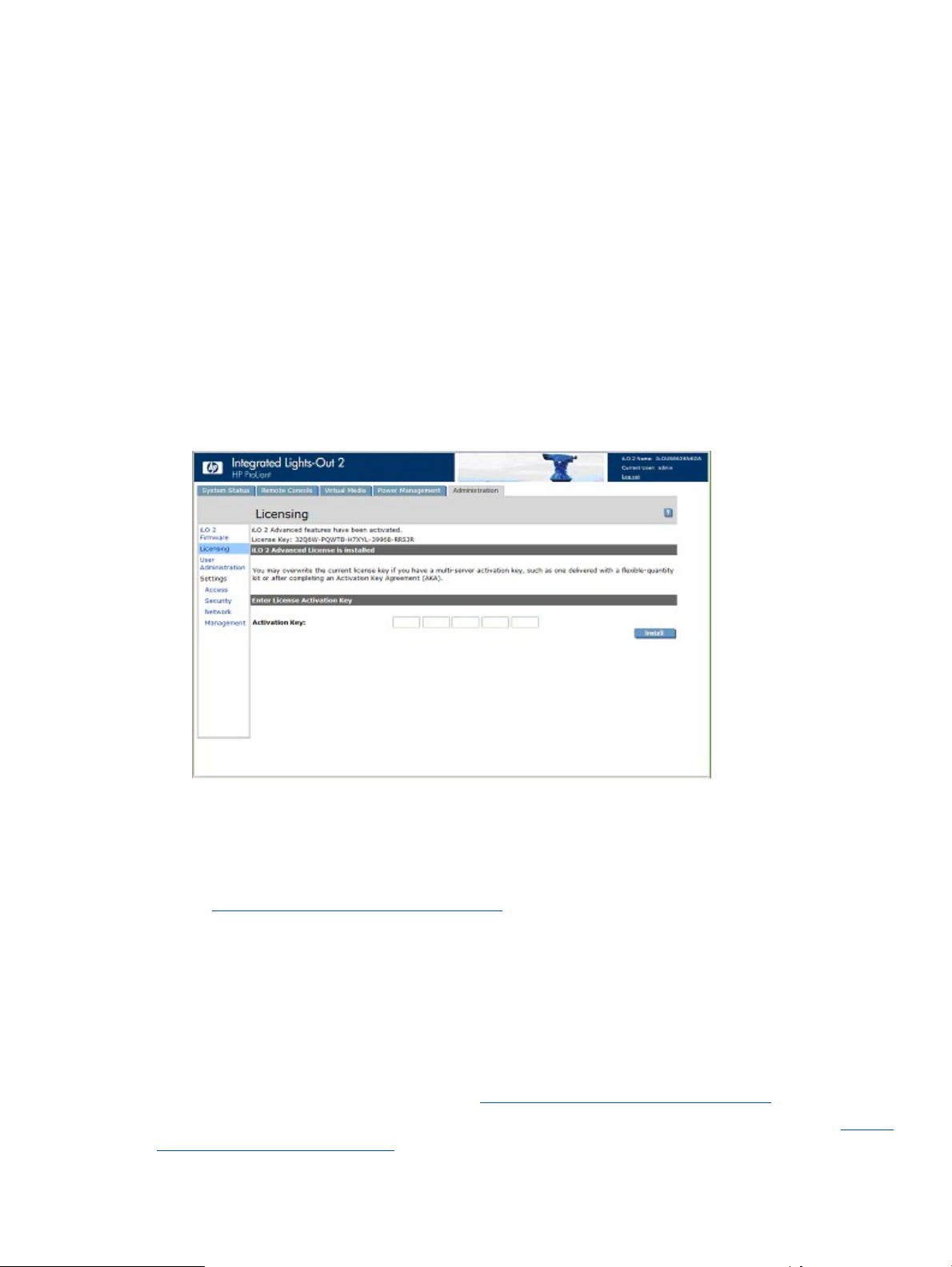
Licensing...............................................................................................................................26
User administration.................................................................................................................28
Adding a new user............................................................................................................29
Viewing or modifying existing user settings............................................................................31
Deleting a user..................................................................................................................31
Group administration.........................................................................................................32
Configuring iLO 2 access........................................................................................................33
Services options.................................................................................................................33
Terminal Services Passthrough option...............................................................................35
Terminal Services client requirements...........................................................................35
Enabling the Terminal Services Passthrough option.............................................................36
Terminal Services warning message............................................................................37
Terminal Services Passthrough option display...............................................................37
Remote Console and Terminal Services clients...................................................................37
Terminal Services troubleshooting....................................................................................38
Access options..................................................................................................................38
iLO 2 Remote Console and Remote Serial Console access.......................................................41
Security.................................................................................................................................41
General security guidelines.................................................................................................41
Contents 3
Page 4

Password guidelines......................................................................................................42
Securing RBSU..............................................................................................................42
iLO 2 Security Override Switch administration...................................................................42
Trusted Platform Module support..........................................................................................43
User accounts and access...................................................................................................43
Privileges.....................................................................................................................44
Login security................................................................................................................44
SSH key administration.......................................................................................................44
SSL certificate administration...............................................................................................45
Two-factor authentication....................................................................................................46
Setting up two-factor authentication for the first time...........................................................47
Setting up a user for two-factor authentication...................................................................48
Two-factor authentication login........................................................................................49
Using two-factor authentication with directory authentication...............................................50
Directory settings...............................................................................................................51
Configuring directory settings.........................................................................................51
Directory tests...............................................................................................................53
Encryption........................................................................................................................53
Encryption settings........................................................................................................54
Connecting to the iLO 2 using AES/3DES encryption.........................................................54
HP SIM single sign-on (SSO)...............................................................................................55
Setting up iLO 2 for HP SIM SSO....................................................................................55
Adding HP SIM trusted servers........................................................................................56
Setting up HP SIM SSO..................................................................................................57
Remote Console Computer Lock...........................................................................................58
Network................................................................................................................................60
Network Settings...............................................................................................................60
iLO 2 subsystem name limitations....................................................................................61
iLO 2 Shared Network Port.............................................................................................61
iLO 2 Shared Management Port features and restrictions................................................62
Enabling the iLO 2 Shared Network Port feature...........................................................62
Re-enabling the dedicated iLO 2 management port.......................................................63
DHCP/DNS Settings..........................................................................................................64
SNMP/Insight Manager settings...............................................................................................65
Enabling SNMP alerts........................................................................................................65
SNMP generated trap definitions.........................................................................................66
Configuring Insight Manager integration...............................................................................67
Static IP bay configuration.......................................................................................................68
Configuring a ProLiant BL p-Class blade enclosure..................................................................68
Configuring static IP bay settings..........................................................................................69
ProLiant BL p-Class standard configuration parameters............................................................69
ProLiant BL p-Class advanced configuration parameters...........................................................69
Enabling iLO 2 IP address assignment..................................................................................70
HP BladeSystem setup.........................................................................................................70
The iLO 2 firmware configuration screen...........................................................................71
Verify Server RAID Configuration screen...........................................................................71
Connect Virtual Media screen.........................................................................................72
Install Software screen...................................................................................................72
iLO 2 diagnostic port configuration parameters......................................................................72
4 Using iLO 2.............................................................................................74
System status and status summary information............................................................................74
System Information Summary...............................................................................................75
Fans............................................................................................................................76
Temperatures................................................................................................................76
4 Contents
Page 5

Power..........................................................................................................................77
Processors....................................................................................................................77
Memory.......................................................................................................................77
NIC.............................................................................................................................77
iLO 2 Log.........................................................................................................................77
IML..................................................................................................................................78
Diagnostics.......................................................................................................................79
Insight Agents....................................................................................................................80
iLO 2 Remote Console.............................................................................................................80
Remote Console overview and licensing options.....................................................................81
Remote Console settings.....................................................................................................81
Remote console hot keys.................................................................................................83
Supported hot keys........................................................................................................84
Hot keys and international keyboards..............................................................................85
Hot keys and Virtual Serial Port.......................................................................................85
IRC Fullscreen....................................................................................................................85
Integrated Remote Console option........................................................................................85
Optimizing mouse performance for Remote Console or Integrated Remote Console................88
High Performance Mouse settings....................................................................................88
Multi-user access to the Integrated Remote Console................................................................89
Using Console Capture.......................................................................................................90
Using HP iLO Video Player..................................................................................................90
iLO Video Player user interface.......................................................................................91
iLO Video Player controls...............................................................................................92
Acquiring the Remote Console.............................................................................................92
Remote Console.................................................................................................................93
Remote Console features and controls..............................................................................94
Recommended client settings..........................................................................................94
Recommended server settings.........................................................................................95
Microsoft Windows Server 2003 settings.....................................................................95
Red Hat Linux and SUSE Linux server settings...............................................................95
Text-based remote console overview.....................................................................................95
Text-based console during POST......................................................................................95
Text-based console after POST........................................................................................96
Using the iLO 2 Text Console.....................................................................................97
Customizing iLO 2 Text Console.................................................................................97
Using a Linux session................................................................................................99
Virtual serial port and remote serial console......................................................................99
Remote Serial Console............................................................................................100
Virtual Serial Port enhancements...............................................................................101
Windows EMS Console...........................................................................................102
Virtual media.......................................................................................................................104
Using iLO 2 Virtual Media devices.....................................................................................104
Virtual Media and Windows 7.....................................................................................105
iLO 2 Virtual Floppy/USBKey........................................................................................105
Virtual Floppy/USB Key operating systems notes.........................................................106
Operating system USB support.................................................................................107
Mounting USB Virtual Floppy/USBKey in NetWare 6.5...............................................107
Mounting USB Virtual Media/USBKey in Linux...........................................................108
Changing diskettes.................................................................................................109
iLO 2 Virtual CD/DVD-ROM.........................................................................................109
Virtual Media CD/DVD-ROM operating system notes..................................................110
Mounting USB Virtual Media CD/DVD-ROM in Linux..................................................110
Creating iLO 2 disk image files.....................................................................................111
Virtual folder...................................................................................................................111
Contents 5
Page 6

Virtual folder operating system notes..................................................................................112
Power management..............................................................................................................112
Server power settings.......................................................................................................113
Server power data...........................................................................................................115
Processor states...............................................................................................................116
Power efficiency...............................................................................................................117
Graceful shutdown...........................................................................................................118
Brown-Out recovery.........................................................................................................119
ProLiant BL p-Class Advanced management..............................................................................119
Rack View.......................................................................................................................120
Blade configuration and information..............................................................................121
Enclosure information...................................................................................................122
Power enclosure information.........................................................................................122
Network component information...................................................................................123
iLO 2 control of ProLiant BL p-Class server LEDs....................................................................123
Server POST tracking...................................................................................................123
Insufficient power notification........................................................................................124
ProLiant BL p-Class alert forwarding....................................................................................124
ProLiant BladeSystem HP Onboard Administrator......................................................................124
iLO 2 BL c-Class tab.........................................................................................................124
Enclosure bay IP addressing..............................................................................................125
Dynamic power capping for server blades..........................................................................127
iLO 2 Virtual Fan.............................................................................................................128
iLO option.......................................................................................................................128
Web Administration.........................................................................................................128
BL p-Class and BL c-Class features......................................................................................129
5 Directory services...................................................................................130
Overview of directory integration............................................................................................130
Benefits of directory integration..............................................................................................130
Advantages and disadvantages of schema-free directories and HP schema directory.....................131
Schema-free directory integration.......................................................................................131
Setting up Schema-free directory integration.............................................................................132
Active Directory preparation..............................................................................................132
Introduction to certificate services..................................................................................132
Installing certificate services..........................................................................................132
Verifying certificate services..........................................................................................133
Configuring Automatic Certificate Request......................................................................133
Schema-free browser-based setup.......................................................................................133
Schema-free scripted setup................................................................................................133
Schema-free HPLOMIG-based setup....................................................................................134
Schema-free setup options.................................................................................................134
Schema-free nested groups................................................................................................135
Setting up HP schema directory integration..............................................................................136
Features supported by HP schema directory integration.........................................................136
Setting up directory services..............................................................................................136
Schema documentation.....................................................................................................137
Directory services support.................................................................................................137
Schema required software.................................................................................................137
Schema installer..............................................................................................................138
Schema Preview..........................................................................................................138
Setup.........................................................................................................................138
Results.......................................................................................................................139
Management snap-in installer............................................................................................140
Directory services for Active Directory.................................................................................140
6 Contents
Page 7

Active Directory installation prerequisites........................................................................140
Installing Active Directory on Windows Server 2008.......................................................141
Directory services preparation for Active Directory...........................................................141
Snap-in installation and initialization for Active Directory..................................................142
Example: Creating and configuring directory objects for use with iLO 2 in Active Directory....143
Directory services objects.............................................................................................145
Active Directory snap-ins.........................................................................................146
Active Directory role restrictions................................................................................147
Active Directory Lights-Out management.........................................................................148
Directory services for eDirectory.........................................................................................149
eDirectory installation prerequisites................................................................................149
Snap-in installation and initialization for eDirectory..........................................................150
Creating and configuring directory objects for use with LOM devices in eDirectory..............150
Directory Services objects for eDirectory.........................................................................152
Role managed devices............................................................................................152
Members...............................................................................................................153
eDirectory Role Restrictions...........................................................................................154
Time restrictions......................................................................................................154
Enforced client IP address or DNS name access.........................................................154
eDirectory Lights-Out Management................................................................................155
User login using directory services.....................................................................................156
Directory-enabled remote management....................................................................................156
Introduction.....................................................................................................................156
Creating roles to follow organizational structure...................................................................157
Using existing groups..................................................................................................157
Using multiple roles.....................................................................................................157
How directory login restrictions are enforced.......................................................................158
Restricting roles...........................................................................................................158
Role time restrictions...............................................................................................159
Role address restrictions..........................................................................................159
User restrictions...........................................................................................................159
User address restrictions..........................................................................................159
How user time restrictions are enforced......................................................................160
Creating multiple restrictions and roles...........................................................................160
Using bulk import tools.....................................................................................................161
HPLOMIG directory migration utility........................................................................................162
Introduction to HPLOMIG utility..........................................................................................162
Compatibility..................................................................................................................162
HP Lights-Out directory package........................................................................................163
Using HPLOMIG..............................................................................................................163
Finding management processors...................................................................................163
Upgrading firmware on management processors.............................................................165
Selecting a directory access method..............................................................................166
Naming management processors..................................................................................167
Configuring directories when HP Extended schema is selected..........................................168
Configuring directories when schema-free integration is selected........................................169
Setting up management processors for directories............................................................170
Directory services schema......................................................................................................171
HP Management Core LDAP OID classes and attributes........................................................171
Core classes...............................................................................................................172
Core attributes............................................................................................................172
Core class definitions...................................................................................................172
hpqTarget..............................................................................................................172
hpqRole................................................................................................................172
hpqPolicy..............................................................................................................173
Contents 7
Page 8

Core attribute definitions..............................................................................................173
hpqPolicyDN.........................................................................................................173
hpqRoleMembership...............................................................................................173
hpqTargetMembership............................................................................................173
hpqRoleIPRestrictionDefault......................................................................................173
hpqRoleIPRestrictions...............................................................................................174
hpqRoleTimeRestriction............................................................................................174
Lights-Out Management specific LDAP OID classes and attributes...........................................175
Lights-Out Management classes.....................................................................................175
Lights-Out Management attributes..................................................................................175
Lights-Out Management class definitions........................................................................175
hpqLOMv100........................................................................................................175
Lights-Out Management attribute definitions....................................................................175
hpqLOMRightLogin.................................................................................................175
hpqLOMRightRemoteConsole...................................................................................176
hpqLOMRightVirtualMedia......................................................................................176
hpqLOMRightServerReset.........................................................................................176
hpqLOMRightLocalUserAdmin..................................................................................176
hpqLOMRightConfigureSettings................................................................................177
6 HP Systems Insight Manager integration....................................................178
Integrating iLO 2 with HP SIM................................................................................................178
HP SIM functional overview....................................................................................................178
Establishing SSO with HP SIM................................................................................................178
HP SIM identification and association......................................................................................179
HP SIM status..................................................................................................................179
HP SIM links....................................................................................................................179
HP SIM systems lists..........................................................................................................180
Receiving SNMP alerts in HP SIM...........................................................................................180
HP SIM port matching...........................................................................................................181
Reviewing Advanced Pack license information in HP SIM...........................................................181
7 Troubleshooting iLO 2.............................................................................182
iLO 2 POST LED indicators.....................................................................................................182
Event log entries...................................................................................................................183
Hardware and software link-related issues................................................................................186
JVM support........................................................................................................................186
Login issues.........................................................................................................................187
Login name and password not accepted.............................................................................187
Directory user premature logout.........................................................................................187
iLO 2 Management Port not accessible by name..................................................................187
iLO 2 RBSU unavailable after iLO 2 and server reset.............................................................188
Inability to access the login page.......................................................................................188
Inability to access iLO 2 using Telnet..................................................................................188
Inability to access virtual media or graphical remote console.................................................188
Inability to connect to iLO 2 after changing network settings..................................................188
Inability to connect to the iLO 2 Diagnostic Port...................................................................188
Inability to connect to the iLO 2 processor through the NIC...................................................189
Inability to log in to iLO 2 after installing the iLO 2 certificate................................................189
Firewall issues.................................................................................................................189
Proxy server issues...........................................................................................................190
Two-factor authentication error...........................................................................................190
Troubleshooting alert and trap issues.......................................................................................190
Inability to receive HP SIM alarms (SNMP traps) fromiLO 2....................................................191
iLO 2 Security Override switch...........................................................................................191
Authentication code error message.....................................................................................191
8 Contents
Page 9

Troubleshooting directory issues..............................................................................................191
Domain/name format login issues......................................................................................191
ActiveX controls are enabled and I see a prompt but the domain/name login format does not
work..............................................................................................................................192
User contexts do not appear to work..................................................................................192
Directory user does not logout after the directory timeout has expires......................................192
Troubleshooting Remote Console issues...................................................................................192
Remote Console applet has a red X when running Linux client browser....................................192
Inability to navigate the single cursor of the Remote Console to corners of the Remote Console
window..........................................................................................................................192
Remote Console no longer opens on the existing browser session...........................................193
Remote console text window not updating properly..............................................................193
Remote Console turns gray or black...................................................................................193
Remote Serial Console troubleshooting...............................................................................193
Troubleshooting Integrated Remote Console issues....................................................................194
Internet Explorer 7 and a flickering remote console screen.....................................................194
Configuring Apache to accept exported capture buffers........................................................194
No console replay while server is powered down.................................................................195
Skipping information during boot and fault buffer playback...................................................195
Out of Memory error starting Integrated Remote Console......................................................195
Session leader does not receive connection request when IRC is in replay mode.......................195
Keyboard LED does not display correctly.............................................................................195
Inactive IRC.....................................................................................................................196
IRC Failed to connect to server error message......................................................................196
IRC toolbar icons do not update........................................................................................196
GNOME interface does not lock........................................................................................197
Repeating keys on the Remote Console...............................................................................197
Remote Console playback does not work when the host server is powered off..........................197
Troubleshooting SSH and Telnet issues.....................................................................................197
Initial PuTTY input slow.....................................................................................................197
PuTTY client unresponsive with Shared Network Port.............................................................197
SSH text support from a Remote Console session..................................................................197
Troubleshooting terminal services issues...................................................................................197
Terminal Services button is not working...............................................................................197
Terminal Services proxy stops responding............................................................................198
Troubleshooting video and monitor issues................................................................................198
General guidelines...........................................................................................................198
Telnet displays incorrectly in DOS......................................................................................198
Video applications not displaying in the Remote Console......................................................198
User interface is not displaying correctly.............................................................................198
Troubleshooting Virtual Media issues.......................................................................................198
Virtual Media applet has a red X and does not display.........................................................199
Virtual Floppy media applet is unresponsive........................................................................199
Troubleshooting iLO Video Player issues...................................................................................199
Video capture file does not play........................................................................................199
Video capture file plays erratically......................................................................................199
Troubleshooting Remote Text Console issues.............................................................................199
Viewing the Linux installer in the text console.......................................................................199
Passing data through an SSH terminal................................................................................199
Troubleshooting miscellaneous issues.......................................................................................199
Cookie sharing between browser instances and iLO 2..........................................................199
Shared instances.........................................................................................................200
Cookie order behavior.................................................................................................200
Displaying the current session cookie.............................................................................201
Preventing cookie-related user issues..............................................................................201
Contents 9
Page 10

Inability to access ActiveX downloads.................................................................................201
Inability to get SNMP information from HP SIM....................................................................201
Incorrect time or date of the entries in the event log..............................................................201
Inability to upgrade iLO 2 firmware....................................................................................201
Diagnostic steps..........................................................................................................202
iLO 2 network flash recovery.............................................................................................202
Recovering from a bad iLO 2 flash image using network flash recovery...................................202
Recovering from a bad iLO 2 flash image using the HP Smart Update Firmware DVD...............203
The iLO 2 firmware does not respond to SSL requests............................................................204
Testing SSL......................................................................................................................204
Resetting iLO 2................................................................................................................204
Server name still present after ERASE utility is executed.........................................................204
Troubleshooting a remote host...........................................................................................205
8 Technical support...................................................................................206
Support information..............................................................................................................206
HP contact information..........................................................................................................207
Before you contact HP...........................................................................................................207
Acronyms and abbreviations.......................................................................208
Index.......................................................................................................211
10 Contents
Page 11

1 Overview
The iLO 2 firmware provides multiple ways to configure, update, and operate servers remotely.
The HP Integrated Lights-Out 2 User Guide describes these features and how to use them with the
browser-based interface and RBSU. Some features are licensed features and may only be accessed
after purchasing an optional license. For more information, see “Licensing” (page 26).
The HP Integrated Lights-Out Management Processor Scripting and Command Line Resource Guide
describes the syntax and tools available to use iLO 2 through a command-line or scripted interface.
Click the link for the guide http://h20000.www2.hp.com/bizsupport/TechSupport/
DocumentIndex.jsp?contentType=SupportManual&lang=en&cc=us&docIndexId=64179&
taskId=135&prodTypeId=18964&prodSeriesId=1146658.
This manual discusses HP Integrated Lights-Out 2 firmware version 2.09 for ProLiant ML/DL servers,
as well as ProLiant BladeSystem server blades.
New in this release of iLO 2
The iLO 2 firmware version 2.09 adds:
• iLO 2 Enhanced CLI prompt and Virtual Serial Port Log
• Support for SUSE Linux 10 and 11 (32– and 64–bit)
iLO 2 Overview
The iLO 2 firmware can remotely perform most functions that otherwise require a visit to servers at
the data center, computer room, or remote location. The following are just a few of the iLO 2
features.
• Remote Console and virtual power – Enables you to view a stalled remote server with blue
screen conditions and restart the server without onsite assistance.
• Remote Console – Enables you to change BIOS settings when necessary.
• Virtual KVM technology – Provides a high-performance remote console that enables you to
remotely administer operating systems and applications in everyday situations.
• Virtual CD/DVD or floppy – Enables you to install an operating system or flash system firmware
over the network from images on your workstations or on centralized web servers.
• Virtual Folder – Enables you to update operating system drivers or copy system files without
physical media or creating a disk image.
• Scripting – Enables you to use virtual power and virtual media in other scripting tools to
automate deployment and provisioning.
• Active participation in monitoring and maintaining server health, referred to as embedded
health. iLO 2 monitors temperatures in the server and sends corrective signals to the fans to
maintain proper server cooling. In addition to temperature monitoring, iLO 2 provides fan
status monitoring and monitoring of the status of the power supplies, voltage regulators, and
the internal hard drives.
These examples are just a few ways iLO 2 is used to manage HP ProLiant servers from your office,
home, or travel location. As you begin using iLO 2 and defining your specific infrastructure
requirements, refer to this guide for additional ways to simplify your remote server management
needs.
For information about the features available in each version of iLO 2, see “Licensing” (page 26).
New in this release of iLO 2 11
Page 12

Differences between iLO 2 and iLO
The iLO 2 firmware is based on the iLO and shares many common features. However, to use iLO
2 to access a pre-operating system, text-based remote console, you must use the remote serial
console. For more information, see “Text-based remote console overview” (page 95).
The following table highlights the differences between iLO 2 and iLO.
Standard features
port)
maintenance
Advanced features
iLOiLO 2Feature
Pre-OS and OSPre-OSText console
Pre-OS and OSPre-OS and OSRemote Serial Console (virtual serial
NoYesServer health monitoring and
Pre-OS and OSPre-OS and OSText console
YesYes (Virtual KVM )Remote console
NoYesIntegrated Remote Console
NoYesSupport for Microsoft JVM
HP Insight Control server deployment
HP Insight Control server deployment integrates with iLO 2 to enable the management of remote
servers and the performance of remote console operations, regardless of the state of the operating
system or hardware.
The deployment server provides the capability to use the power management features of iLO 2 to
power on, power off, or cycle power on the target server. Each time a server connects to the
deployment server, the deployment server polls the target server to determine whether a LOM
management device is installed. If installed, the server gathers information including the DNS
name, IP address, and user login name. Security is maintained by requiring the user to enter a
correct password.
For more information about the HP Insight Control server deployment, see the documentation that
ships on the HP Insight Software DVD, or the HP Insight Control webpage at http://www.hp.com/
go/insightcontrol.
YesYesRemote Console Acquire button
YesYesTerminal Services integration
YesYesHP schema directory integration
YesYesSchema-free directory integration
YesYesTwo-factor authentication
YesYesPower Regulator reporting
YesYesVirtual Floppy and CD/DVD-ROM
YesYesUSB key virtual media
NoYesVirtual folder
12 Overview
Page 13

Server management through IPMI version 2.0 compliant applications
Server management through the IPMI is a standardized method for controlling and monitoring the
server. iLO 2 provides server management based on the IPMI version 2.0 specification.
The IPMI specification defines a standardized interface for platform management. The IPMI
specification defines the following types of platform management:
• Monitoring of system information, such as fans, temperatures, and power supplies
• Recovery capabilities, such as system resets and power on/off operations
• Logging capabilities, for abnormal events such as over temperature readings or fan failures
• Inventory capabilities, such as identifying failed hardware components
IPMI communications are dependent on the BMC and the SMS. The BMC manages the interface
between the SMS and the platform management hardware. iLO 2 emulates the BMC functionality
and the SMS functionality can be provided by various industry-standard tools. For additional
information, see the IPMI specification on the Intel website at http://www.intel.com/design/servers/
ipmi/tools.htm.
The iLO 2 firmware provides the KCS interface, or open interface, for SMS communications. The
KCS interface provides a set of I/O mapped communications registers. The default system base
address for the I/O mapped SMS Interface is 0xCA2 and is byte aligned at this system address.
The KCS interface is accessible to SMS software that is running on the local system. Examples of
compatible SMS software applications include:
• IPMI version 2.0 Command Test Tool is a low-level MS-DOS command line tool that enables
hex-formatted IPMI commands to be sent to an IPMI BMC that implements the KCS interface.
You can locate this tool on the Intel website at http://www.intel.com/design/servers/ipmi/
tools.htm.
• IPMItool is a utility for managing and configuring devices that support the IPMI version 1.5
and version 2.0 specifications and can be used in a Linux environment. You can locate this
tool on the IPMItool website at http://ipmitool.sourceforge.net/index.html.
IPMI functionality provided by iLO 2
When emulating a BMC for the IPMI interface, iLO 2 supports all mandatory commands listed in
the IPMI version 2.0 specification. See the IPMI version 2.0 specification for a listing of these
commands. Also, the SMS uses the methods described in the specification for determining which
IPMI features are enabled or disabled in the BMC (for example, using the Get Device ID
command).
If the server operating system is running and the health driver is enabled, any IPMI traffic through
the KCS interface can affect the performance of the health driver and overall health performance
of the system. Do not issue any IPMI commands through the KCS interface that might detrimentally
affect the monitoring performed by the health driver. These commands include any commands that
sets or changes IPMI parameters, such as Set Watchdog Timer and Set BMC Global
Enabled. Any IPMI command that simply returns data is safe to use, such as Get Device ID
and Get Sensor Reading.
WS-Management compatibility overview
The iLO 2 firmware implementation of WS-Management is in accordance with the DTMF Web
Services for Management 1.0.0a specification.
iLO 2 Overview 13
Page 14

Authentication:
• The iLO 2 firmware uses basic authentication over SSL, compliant with profile:
wsman:secprofile/https/basic.
• Authenticated users are authorized to execute WS-Management commands in accordance
with designated privileges in their local or directory accounts.
• To enable basic authentication on Windows Vista, enter gpedit.msc at the command prompt
to launch the Group Policy Object Editor. Select Computer Configuration> Administrative
Templates> Windows Components> Windows Remote Management (WinRM)> WinRM Client.
Set Allow Basic authentication to Enabled.
Compatibility:
• WS-Management in iLO 2 is compatible with the Windows Vista WinRM utility, Microsoft
Operations Manager 3, and the Management Pack provided by HP.
• The full set of WS-Management commands is available on iLO 2 servers that support embedded
system health. A greatly reduced subset of these commands is available on servers without
embedded systems health support.
Commands:
The following commands are available for remote invocation of the following devices:
• Server power
• UID
Status:
The WS-Management in iLO 2 returns status information for fans, temperatures, power supplies,
and VRMs.
iLO 2 browser interface overview
The iLO 2 browser interface groups similar tasks for easy navigation and workflow. These tasks
are organized under high-level tabs across the top of the iLO 2 interface. These tabs appear on
the browser interface and include System Status, Remote Console, Virtual Media, Power
Management, and Administration.
Each high-level iLO 2 tab has a menu on the left side of the interface with various options. When
you select a different high-level tab, the menu changes, and displays the options available from
that tab. Each menu option displays a page title, which is a description of the information or settings
available on that page. This page title might not reflect the name that appears on the menu option.
Assistance for all iLO 2 pages is available from iLO 2 Help. Links on each iLO 2 page provide
summary information about the features of iLO 2 and helpful information to optimize its operation.
To access page-specific help, click the question mark (?) on the right side of the browser window.
Typical user tasks are found under the System Status, Remote Console, Virtual Media, and Power
Management tabs of the iLO 2 interface. These tasks are described in “Using iLO 2” (page 74).
The Administration tab is typically used by an advanced or administrative user who must manage
users, configure global and network settings, as well as configure or enable the more advanced
functions of iLO 2. These tasks are discussed in “Setting up iLO 2” (page 17) and “Configuring
iLO 2” (page 24).
Subject-specific areas of iLO 2 functionality and integration are detailed in:
• “Directory services” (page 130)
• “Directory-enabled remote management” (page 156)
• “HPLOMIG directory migration utility” (page 162)
• “HP Systems Insight Manager integration” (page 178)
14 Overview
Page 15

• “Troubleshooting iLO 2” (page 182)
• “Directory services schema” (page 171)
Supported browsers and client operating systems
• Microsoft Internet Explorer 7, Internet Explorer 8, Internet Explorer 9
These browsers are supported on Microsoft Windows products.◦
◦ HP supports Microsoft JVM and SUN Java 1.4.2_13. To download the recommended
JVM for your system configuration, see the website at http://h18006.www1.hp.com/
products/servers/management/ilo_table.html?jumpid=reg_r1002_usen.
• Mozilla Firefox versions 8, 9, and 10
This browser is supported on Red Hat Enterprise Linux Desktop 4 and Novell Linux Desktop
◦
9.
◦ HP supports Microsoft JVM and SUN Java 1.4.2_13. To download the recommended
JVM for your system configuration, see the HP website at http://h18006.www1.hp.com/
products/servers/management/ilo_table.html?jumpid=reg_r1002_usen.
Certain browsers and operating system combinations might not work correctly, depending on the
implementation of the required browser technologies.
Supported server operating system software
iLO 2 is an independent microprocessor running an embedded operating system. The architecture
ensures that the majority of iLO 2 functionality is available, regardless of the host operating system.
For graceful host operating system shutdown, HP SIM integration requires health drivers and
Management Agents or remote console access.
iLO 2 provides two interface drivers:
• The iLO 2 Advanced Server Management Controller Driver (health driver) – Provides system
management support, including monitoring of server components, event logging, and support
for the Management Agents.
• The iLO 2 Management Interface Driver – Enables system software and SNMP Insight Agents
to communicate with iLO 2.
These drivers and agents are available for the following network operating systems:
• Microsoft
Windows 2008 Server◦
◦ Windows 2008 Advanced Server
◦ Windows Server 2003
◦ Windows Server 2003, Web Edition
◦ Windows Small Business Server 2003 (ML300 series)
◦ Windows Vista
• Red Hat
RedHat Enterprise Linux 3 (x86)◦
◦ RedHat Enterprise Linux 3 (AMD64/EM64T)
◦ RedHat Enterprise Linux 4 (x86)
iLO 2 browser interface overview 15
Page 16

◦ RedHat Enterprise Linux 4 (AMD64/EM64T)
◦ RedHat Enterprise Linux 5 (x86)
◦ RedHat Enterprise Linux 5 (AMD64/EM64T)
• SUSE LINUX
◦ SUSE LINUX Enterprise Server 9 (x86)
◦ SUSE LINUX Enterprise Server (AMD64/EM64T)
◦ SUSE LINUX Enterprise Server 10
◦ SUSE LINUX 10 (32– and 64–bit)
◦ SUSE LINUX 11 (32– and 64–bit)
16 Overview
Page 17

2 Setting up iLO 2
Quick setup
To quickly set up iLO 2 by using the default settings for iLO 2 Standard and iLO Advanced features,
follow these steps:
1. To decide how you want to structure networking and security, see“Preparing to set up iLO 2”
(page 17)
2. To connect iLO 2 to the network, see “Connecting to the network” (page 18).
3. If you are not using dynamic IP addressing to configure a static IP address, use the iLO 2
RBSU. See “Configuring the IP address” (page 19).
4. To log into iLO 2 from a supported browser or command line using the default user name,
password, and DNS name provided on the iLO 2 Network Settings tag attached to the server,
see “Logging in to iLO 2 for the first time” (page 20).
5. Change the default user name and password on the administrator account to your predefined
selections.
6. To use the local accounts feature, set up your user accounts, see “Setting up user accounts”
(page 20).
7. To activate iLO 2 advanced features, see “Activating iLO 2 licensed features with a browser”
(page 21).
8. To install the iLO 2 device drivers, see “Installing iLO 2 device drivers” (page 21).
Preparing to set up iLO 2
Before setting up your iLO 2 management processors, you must decide how to handle networking
and security. The following questions can help you configure iLO 2 for your needs:
1. How should iLO 2 connect to the network?
For a graphical representation and explanation of the available connections, see “Connecting
to the network” (page 18). Typically iLO 2 is connected to the network using either:
• A corporate network where both the NIC and the iLO 2 port are connected to the corporate
network. This connection enables access to iLO 2 from anywhere on the network and
reduces the amount of networking hardware and infrastructure required to support iLO
2. However, on corporate networks, network traffic can impede iLO 2 performance.
• A dedicated management network with the iLO 2 port on a separate network. A separate
network improves performance and security because you can physically control which
workstations are connected to the network. A separate network also provides redundant
access to the server when a hardware failure occurs on the corporate network. In this
configuration, iLO 2 cannot be accessed directly from the corporate network.
2. How will iLO 2 acquire an IP address?
To access iLO 2 after connecting it to the network, the management processor must acquire
an IP address and subnet mask using either a dynamic or static process:
• Dynamic IP address is set by default. iLO 2 obtains the IP address and subnet mask from
DNS/DHCP servers. This method is the simplest.
• Static IP address is used to configure a static IP address if DNS/DHCP servers are not
available on the network. A static IP address can be configured in iLO 2 using the RBSU.
If using a static IP, you must have an IP address before starting iLO 2 setup.
Quick setup 17
Page 18

3. What access security is required and what user accounts and privileges are needed?
The iLO 2 firmware provides several options to control user access. You must select one of
the following methods to prevent unauthorized access to corporate IT assets:
• Local accounts with up to 12 user names and passwords can be stored on iLO 2. This is
ideal for small environments such as labs and small- and medium-sized businesses.
• Directory services use the corporate directory (Microsoft Active Directory or Novell
eDirectory) to manage iLO 2 user access. This is ideal for environments with a large
number of frequently changing users. If you plan to use Directory services leave at least
one local account enabled for alternate access. For more information, see “Security”
(page 41).
4. How do you want to configure iLO 2?
The iLO 2 firmware supports various interfaces for configuration and operation. This guide
discusses the following interfaces:
• Using iLO 2 RBSU when the system environment does not use DHCP, DNS, or WINS.
For more information, see “Setting up iLO 2 using iLO 2 RBSU” (page 20).
• Using a browser-based setup when you can connect to iLO 2 on the network using a
browser. This method can also reconfigure a previously configured iLO 2. For more
information, see “Setting up iLO 2 with the browser-based option” (page 21).
• Using SMASH CLP when a command line is accessible through Telnet, SSH, or physical
serial port. For more information, see the HP Integrated Lights-Out Management Processor
Scripting and Command Line Resource Guide at http://h20000.www2.hp.com/
bizsupport/TechSupport/DocumentIndex.jsp?contentType=SupportManual&lang=en&
cc=us&docIndexId=64179&taskId=135&prodTypeId=18964&prodSeriesId=1146658.
The iLO 2 default settings enable you to use most features with no additional configuration. However,
the extensive configuration flexibility of iLO 2 enables customization for multiple enterprise
environments. For all available options, see “Configuring iLO 2” (page 24).
For advanced setup of multiple iLO 2 management processors using scripting commands, the
following methods are available. Scripts are text files written in an XML-based scripting language
called RIBCL. You can use RIBCL scripts to configure iLO 2 on the network, during initial deployment,
or from an already deployed host. Each method is described in the HP Integrated Lights-Out
Management Processor Scripting and Command Line Resource Guide at http://
h20000.www2.hp.com/bizsupport/TechSupport/DocumentIndex.jsp?contentType=SupportManual&
lang=en&cc=us&docIndexId=64179&taskId=135&prodTypeId=18964&prodSeriesId=1146658
• CPQLOCFG is a Microsoft Windows utility that sends RIBCL scripts to iLO 2 over the network.
• HPONCFG is a local, online, and scripted setup utility that runs on the host and passes RIBCL
scripts to the local iLO 2 firmware. This utility has Windows and Linux versions, which require
the iLO 2 Management Interface Driver.
• Perl is a scripting language that you use from Linux clients to send RIBCL scripts to the iLO 2
firmware over the network.
Connecting to the network
Typically, iLO 2 is connected to the network in one of two ways:
• Corporate network, where both ports are connected to the corporate network. In this
configuration, the server has two network ports (one server NIC, and one iLO 2 NIC) connected
to a corporate network.
18 Setting up iLO 2
Page 19

• Dedicated management network, where the iLO 2 port is on a separate network.
Configuring the IP address
This step is necessary only if you are using a static IP address. When using dynamic IP addressing,
your DHCP server automatically assigns an IP address for iLO 2. To simplify installation, HP
recommends using DNS or DHCP with iLO 2.
To configure a static IP address, use the iLO 2 RBSU with the following procedure to disable DNS
and DHCP and configure the IP address and the subnet mask:
1. Restart or power the server on.
2. Press the F8 key when prompted during POST. The iLO 2 RBSU runs.
3. Select Network>DNS/DHCP, press the Enter key, and then select DHCP Enable.
4. Press the spacebar to turn off DHCP. Be sure that DHCP Enable is set to Off, and then save
the changes.
5. Select Network>NIC>TCP/IP, press the Enter key, and then enter the appropriate information
in the IP Address, Subnet Mask, and Gateway IP Address fields.
6. Save the changes.
7. Exit iLO 2 RBSU. The changes take effect when you exit iLO 2 RBSU.
Configuring the IP address 19
Page 20

Logging in to iLO 2 for the first time
The iLO 2 firmware is configured with a default user name, password, and DNS name. Default
user information is located on the iLO 2 Network Settings tag attached to the server containing
the iLO 2 management processor. Use these values to access iLO 2 remotely from a network client
using a standard Web browser.
For security reasons, HP recommends changing the default settings after logging in to iLO 2 for
the first time.
The default values are:
• User name – Administrator
• Password – A random, eight-character, alphanumeric string
• DNS Name – ILOXXXXXXXXXXXX
where XXXXXXXXXXXX represents the serial number of the server
NOTE: User names and passwords are case sensitive.
If you enter an incorrect user name and password, or a log in attempt fails, then iLO 2 imposes a
security delay. For more information on login security, see “Login security” (page 44).
Setting up user accounts
The iLO 2 firmware comes preconfigured with default factory settings, including a default user
account and password. For security reasons, HP recommends changing the default settings after
logging in to iLO 2 for the first time. These changes can be made using any of the iLO 2 user
interfaces. RBSU and browser procedures are explained in this user guide. Other options including
the SMASH CLP and scripting methods are described in the HP Integrated Lights-Out Management
Processor Scripting and Command Line Resource Guide at http://h20000.www2.hp.com/
bizsupport/TechSupport/DocumentIndex.jsp?contentType=SupportManual&lang=en&cc=us&
docIndexId=64179&taskId=135&prodTypeId=18964&prodSeriesId=1146658.
If iLO 2 is connected to a network running DNS or DHCP, you can use it immediately without
changing any settings.
Setting up iLO 2 using iLO 2 RBSU
HP recommends that you use the iLO 2 RBSU to initially set up iLO 2 and configure iLO 2 network
parameters for environments that do not use DHCP and DNS, or WINS. RBSU provides the basic
tools to configure iLO 2 network settings and user accounts to get iLO 2 on the network.
You can use RBSU to configure network parameters, global settings, and user accounts. The iLO
2 RBSU is not intended for continued administration. RBSU is available every time the server is
booted and can be run remotely using the iLO 2 Remote Console.
The iLO 2 RBSU can be disabled in the Global Settings preferences. Disabling iLO 2 RBSU prevents
reconfiguration from the host unless the iLO 2 Security Override Switch is set.
To run iLO 2 RBSU to set up local accounts:
1. Restart or power the server on.
2. Press the F8 key when prompted during POST. The iLO 2 RBSU runs.
3. If prompted, enter a valid iLO 2 user ID and password with the appropriate iLO 2 privileges
(Administer User Accounts>Configure iLO 2 Settings). Default account information is located
on the iLO 2 Default Network Settings tag attached to the server containing the iLO 2
management processor. If iLO 2 has not been configured to present a login challenge to the
RBSU, then no prompt appears.
4. Make and save any necessary changes to the iLO 2 configuration.
5. Exit iLO 2 RBSU.
20 Setting up iLO 2
Page 21
Setting up iLO 2 with the browser-based option
If you can connect to iLO 2 on the network with a browser, then use the browser-based setup
method. You can also use this method to reconfigure a previously configured iLO 2.
Access iLO 2 from a remote network client using a supported browser, and provide the default
DNS name, user name, and password. Default DNS name and account information is located on
the iLO 2 Network Settings tag attached to the server containing the iLO 2 management processor.
When you successfully log onto iLO 2, you can change the default values of the local user accounts
by selecting User Administration under the iLO 2 Administration tab.
Activating iLO 2 licensed features with a browser
The Licensing page enables you to view the current license status and enter a key to activate iLO
2 license features. The iLO 2 version and current license information appears in this section. If a
license is installed (including an evaluation license), the license number appears. For more
information about iLO 2 license options, see “Licensing” (page 26).
1. Log into iLO 2 through a supported browser.
2. To display the iLO 2 license activation screen, click Administration>Licensing.
3. Enter the license key. To move between fields, press the Tab key or click inside a field. The
Activation Key field advances automatically as you enter data. To clear the fields and reload
the page, click Licensing.
4. Click Install. The EULA confirmation appears. The EULA details are available on the HP website
at http://www.hp.com/servers/lights-out and with the license kit.
5. Click OK.
The advanced features of iLO 2 are now enabled.
Installing iLO 2 device drivers
The iLO 2 Management Interface Driver enables system software such as SNMP Insight Agents
and the Terminal Services passthrough service to communicate with iLO 2.
The device drivers required to support iLO 2 are part of the PSP located on the SmartStart CD,
Management CD, or on the HP website at http://www.hp.com/servers/lights-out.
All the support drivers for your server and iLO 2 can be downloaded from the HP website at http://
www.hp.com/servers/lights-out.
To download the drivers:
Activating iLO 2 licensed features with a browser 21
Page 22

1. Click the iLO 2 graphic.
2. Select Software and Drivers.
Microsoft device driver support
The device drivers that support the iLO 2 are part of the PSP that is located on the HP website at
http://www.hp.com/support or on the SmartStart CD. Before you install the Windows drivers,
obtain the Windows documentation and the latest Windows Service Pack.
iLO 2 prerequisite files:
• CPQCIDRV.SYS – Provides the iLO 2 Management Interface Driver support.
• CPQASM2.SYS, SYSMGMT.SYS, and SYSDOWN.SYS – Provide the iLO 2 Advanced Server
Management Controller Driver support.
PSP for Microsoft Windows products includes an installer that analyzes system requirements and
installs all drivers. The PSP is available on the HP website at http://www.hp.com/support or on
the SmartStart CD.
To install the drivers in the PSP:
1. Download the PSP from the HP website at http://www.hp.com/support.
2. Run the SETUP.EXE file included in the download, and then follow the installation instructions.
For additional information about the PSP installation, read the text file included in the PSP download.
Linux device driver support
You can download the LSP files containing the iLO 2 driver, the foundation agents, and health
agents from the HP website at http://www.hp.com/support. The instructions on how to install or
update the iLO 2 driver are available on the website. The HP Management Agents for Linux are:
• RPM package (hp-snmp-agents) combines the health driver, IML viewer, foundation agents,
health agent, and standard equipment agent into one package.
• RPM package (hp-iLO) combines the RIB driver, rack daemon, RIB agent, and rack agent
into one package.
To load the health and iLO 2 driver packages, enter the following commands:
rpm -ivh hp-snmp-agents-d.vv.v-pp.Linux_version.i386.rpm
rpm -ivh hp-iLO-d.vv.v-pp.Linux_version.i386.rpm
where:
d is the Linux distribution and version
vv.v-pp are version numbers
To remove the health and iLO 2 drivers, enter the following commands:
rpm -e hp-snmp-agents
rpm -e hp-iLO
For additional information, see the HP Software and Drivers website at http://www.hp.com/
support.
Novell NetWare device driver support
The device drivers required to support iLO 2 are part of the PSP that is located on the SmartStart
CD and the HP website at http://www.hp.com/support. The PSP for Novell NetWare includes an
installer that analyzes system requirements and installs all drivers.
iLO 2 requires the following files:
• The CPQHLTH.NLM file provides the Health Driver for Novell NetWare.
• The CPQCI.NLM file provides iLO 2 Management Interface Driver support.
22 Setting up iLO 2
Page 23

When updating iLO 2 drivers, be sure iLO 2 is running the latest version of iLO 2 firmware. You
can obtain the latest version as a Smart Component from the HP website at http://www.hp.com/
servers/lights-out.
Install the drivers download the PSP from the HP website at http://www.hp.com/support to a
NetWare server. After downloading the PSP, follow the Novell NetWare component installation
instructions to complete the installation. For additional information about the PSP installation, read
the text file included in the PSP download.
When using Novell NetWare 6.X, use the ATI ES1000 video driver that is provided by the operating
system for best results.
Installing iLO 2 device drivers 23
Page 24

3 Configuring iLO 2
iLO 2 configuration overview
Typically, an advanced or administrative user who must manage users and configure global and
network settings configures iLO 2. You can configure iLO 2 using the iLO 2 browser-based GUI
or scripting tools such as CPQLOCFG and HPONCFG (described in the HP Integrated Lights-Out
Management Processor Scripting and Command Line Resource Guide at http://
h20000.www2.hp.com/bizsupport/TechSupport/DocumentIndex.jsp?contentType=SupportManual&
lang=en&cc=us&docIndexId=64179&taskId=135&prodTypeId=18964&prodSeriesId=1146658.
The iLO 2 Administration tab enables you to configure and manage user settings, SNMP alerting
(through integration with HP SIM), security settings, licensing, certificate administration, directory
settings, and network environment settings. The Administration tab includes the following menu
options:
• iLO 2 Firmware. See“Upgrading iLO 2 firmware” (page 24).
• Licensing. See “Licensing” (page 26).
• User Admininstration. See “User administration” (page 28)
• Settings
Access. See “Configuring iLO 2 access” (page 33)◦
◦ Security. See “Security” (page 41)
◦ Network. See “Network” (page 60)
◦ Management. See “SNMP/Insight Manager settings” (page 65)
Upgrading iLO 2 firmware
Firmware upgrades enhance the functionality of iLO 2. You can find the latest firmware on the HP
website at http://www.hp.com/servers/lights-out. Select your iLO 2 product, and then select
Software & Drivers. After the software and drivers page appears, select your iLO 2 product and
operating system, and then click Locate Software. You can also locate your iLO 2 software by
selecting the Operating System and Category options.
You must have the Configure iLO 2 privilege (configure local device settings) to update the firmware
unless, you set the security override switch. For more information, see “iLO 2 Security Override
Switch administration” (page 42). If the security override switch is set, any iLO 2 user can update
the firmware. You must run firmware updates from an Administrator or root context on the host
operating system.
To update the iLO 2 choose one of the following methods:
• Online firmware update – Download the appropriate operating system component and run
it from the Administrator or root context of the operating system. The online firmware update
software runs on the host operating system and updates the iLO 2 firmware without requiring
you to log in to iLO 2.
• Offline firmware update for SmartStart maintenance – Download the iLO 2 firmware image
file you plan to install, and see “Upgrading iLO 2 with a browser” (page 25).
• Firmware Maintenance CD-ROM – Download the component to create a bootable CD that
contains many firmware updates for ProLiant servers and options.
• Scripting with CPQLOCFG – Download the CPQLOCFG component to get the network-based
scripting utility CPQLOCFG. CPQLOCFG enables you to use RIBCL scripts that perform firmware
24 Configuring iLO 2
Page 25

updates, iLO 2 configuration, and iLO 2 operations in bulk, securely over the network. HP
recommends that Linux users review the HP Lights-Out XML PERL Scripting Samples for Linux.
• Scripting with HPONCFG – Download the HPONCFG component to get the host-based scripting
utility HPONCFG. This utility enables you to use RIBCL scripts that perform firmware updates,
Lights-Out processor configuration and operations in bulk, from Administrator or root account
access on supported host operating systems.
• HP Directories Support for Management Processors – Download the HP Directories Support
for Management Processors executable file to get the directory support components. One of
the components, HPLOMIG, can be used to discover iLO 2 processors, and update the firmware.
You do not have to use directory integration to take advantage of this functionality.
Upgrading iLO 2 with a browser
You can complete the firmware upgrade from any network client using a supported browser. You
must have the Update iLO 2 Firmware privilege to upgrade the iLO 2 firmware. The most recent
firmware for iLO 2 is available on the HP website at http://www.hp.com/servers/lights-out. To
upgrade the iLO 2 firmware using a supported browser:
1. Log in to iLO 2 with an account that has the Configure iLO 2 Settings privilege.
2. Click Administration>Upgrade iLO 2 Firmware. The Upgrade iLO 2 Firmware page appears.
3. Enter the file name in the New firmware image field or browse for the file.
4. Click Send firmware image. The firmware upgrade takes a few minutes. A progress bar
displays the progress of the firmware upgrade.
Do not interrupt an Upgrade iLO 2 Firmware session. The iLO 2 system automatically resets after
a successful firmware upgrade. The iLO 2 system reset does not affect the host operating system
and server.
If the firmware upgrade is interrupted or fails, attempt the upgrade again immediately. Do not
reset the iLO 2 system before reattempting a firmware upgrade.
Updating the firmware using the maintenance CD
To use HP Smart Update Manager on the Firmware Maintenance CD:
1. Place the Firmware Maintenance CD on a USB key using the USB Key Creator Utility.
2. Copy CP009768.exe to the /compaq/swpackages directory on the USB Key.
3. Follow HP Smart Update Manager steps to complete firmware update.
Upgrading iLO 2 firmware 25
Page 26

Recovering from a failed iLO 2 firmware update
To recover from a failed firmware update using the HP Drive Key Boot Utility:
1. Copy the iLO 2 offline flash component to your USB drive key.
2. Verify that the iLO 2 security override switch is set to disabled.
3. Boot the USB drive key containing the iLO 2 flash component.
To download the HP Drive Key Boot Utility and for information on how to create a boot USB
key, see the HP website at http://www.hp.com/go/support.
4. After the first screen displays, switch to text console by pressing the Ctrl+Alt+F1 keys.
5. Switch to the directory where the flash component is stored by entering cd
/mnt/usb/components/ at the # prompt.
6. Remove the loaded HP Lights-Out driver by entering the following commands:
/etc/init.d/hp-snmp-agents stop
/etc/init.d/hp-ilo stop
or
/etc/init.d/hpasm stop
7. Run the component using the - -direct option. For example:
./CP00xxxx.scexe – –direct
8. Enter y at the Continue (y/n)? prompt.
9. After programming is successfully completed, set the security override switch to enabled and
reboot the server.
Downgrading the iLO 2 firmware
If you downgrade the iLO 2 firmware, you must remove the iLO 2 1.30 Remote Console ActiveX
applet 1.3.0.19 from your Internet Explorer client browser. To remove the applet:
1. Open Internet Explorer.
2. Select Tools>Internet Options>Settings>View objects.
3. To remove 1.30.19, right-click iLO2 Remote console 1.3.0.18.
Licensing
HP iLO Advanced Pack and HP iLO Advanced Pack for Blade System licenses activate optional
iLO 2 features that are not bundled with an unlicensed system.
If you purchase the iLO Advanced Pack or the iLO Advanced Pack for BladeSystem with any Insight
Control software suite or iLO Power Management Pack, HP provides Technical Support and Update
Services. For more information, see “Support information” (page 206).
If you purchase the iLO Advanced Pack or the iLO Advanced Pack for Blade System as a one-time
activation of licensed features, you must purchase future functional upgrades. For more information,
see “Support information” (page 206).
One iLO Advanced or iLO Advanced Pack for Blade System license is required for each server on
which the product is installed and used. Licenses are nontransferable. You cannot license an HP
ProLiant ML/DL server with an iLO Advanced for BladeSystem. For additional information, see the
EULA.
HP will continue to provide maintenance releases with fixes as well as iLO Standard and iLO
Standard Blade Edition feature enhancements at no extra charge.
A 60-day evaluation license key is available for download from the HP website. The evaluation
license activates and enables access to iLO 2 Advanced features. You can only install one evaluation
license per iLO 2. When the evaluation period expires, the iLO 2 features deactivate.
The following versions of iLO 2 are available:
26 Configuring iLO 2
Page 27

NOTE: The features annotated with an asterisk (*) are not supported on all systems.
reset control
through POST
POST
configuration
standard CLP
Scripting
iLO 2 AdvancedFeature
BladeSystem
iLO 2 StandardiLO 2 Advanced for
iLO 2 Standard Blade
Edition
XXXXVirtual power and
XXXXServer console access
– –– –XXText console after
XXXXEvent logs
XXXXSystem health* and
XXXXUID
XXXXDMTF SMASH
XXXXRIBCL/XML scripting
XXXXWS Management
XXXXBrowser access
XXXXSSH access
console
support*
passthrough
reporting*
reporting*
capping
– –X– –XShared network port
XXXXSerial access
XXXXRemote serial console
X– –XXIntegrated remote
X– –XXRemote console
X– –XXVirtual media applet
X– –XXSecure digital card
X– –XXTerminal services
– –– –XXVirtual media scripting
– –– –XXDirectory integration
XXXX24 hour power
– –– –XXReal-time power
– –– –XXDynamic power
authentication
– –– –XXGroup power capping
– –– –XXTwo-factor smart card
– –– –XXHP SIM single sign-on
Licensing 27
Page 28

iLO 2 Standard Blade
Edition
– –– –XXKernel debugger for
– –– –XXConsole replay
– –– –XXShared remote
– –– –XXBoot/fault console
XXXXiLO video player
XXXXEnhanced CLI prompt
– –– –XXVirtual Serial port log
Windows
console
capture
(license required for
capture)
iLO 2 AdvancedFeature
BladeSystem
iLO 2 StandardiLO 2 Advanced for
In addition to the standard iLO 2 single-server licenses, two other licensing options are available:
• The Flexible Quantity License Kit enables you to purchase a single software package, one
copy of the documentation, and a single license key to activate the exact number of licenses
requested.
• The Activation Key Agreement enables a volume purchase of ProLiant Essentials and Insight
Control software over time, typically in conjunction with new ProLiant servers that are acquired
on a regular basis.
User administration
The iLO 2 firmware enables you to manage user accounts stored locally in the secure iLO 2 memory
and directory group accounts. Use MMC or ConsoleOne to manage directory user accounts.
The iLO 2 firmware supports up to 12 users with customizable access rights, login names, and
advanced password encryption. Privileges control individual user settings. Users can have privileges
customized to their individual access requirements. To support more than 12 users, you must have
the Advanced Pack, which enables integration with an unlimited number of directory-based user
accounts.
You must have the Administer User Accounts privilege to view iLO 2 users, add new users, and
modify or delete existing users. If you do not have this privilege, you can view and modify only
your account.
To access local accounts, click Administration>User Administration>Local Accounts.
28 Configuring iLO 2
Page 29
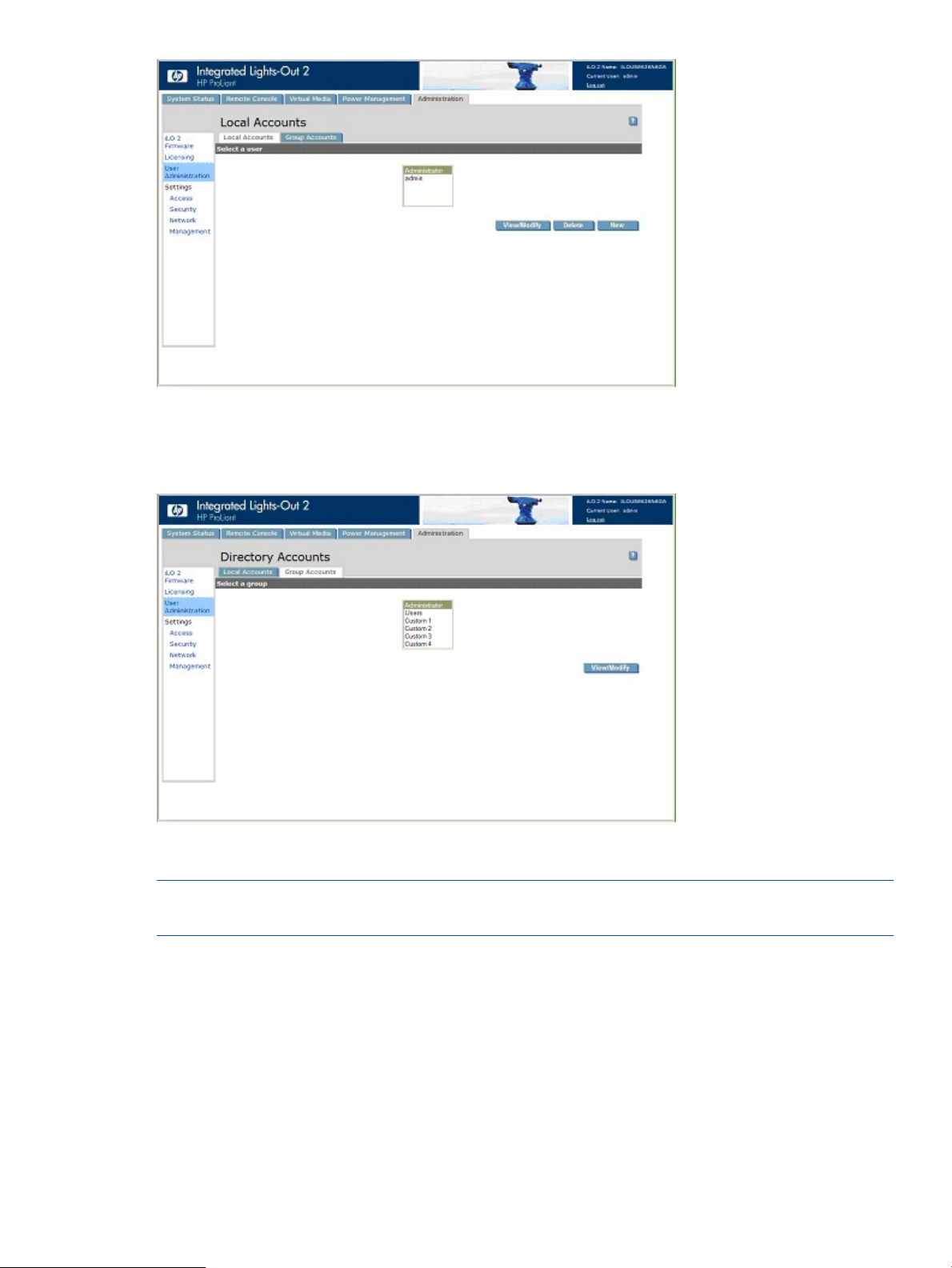
iLO 2 Directory Accounts enables you to view iLO 2 groups and modify the settings for those
groups. You must have the Administer Directory Groups privilege. To access Directory Accounts,
click Administration>User Administration>Group Accounts.
Adding a new user
NOTE: Only users with the Administer User Accounts privilege can manage other users on iLO
2.
You can assign a different access privilege to each user. Each user can have a unique set of
privileges designed for the tasks that the user must perform. You can grant or deny access to critical
functions such as remote access, user management, virtual power, and other features.
To add a new user to iLO 2:
1. Log in to iLO 2 using an account that has the Administer User Accounts privilege.
2. Click Administration.
3. Select User Administration>Local Accounts.
4. Click New.
User administration 29
Page 30
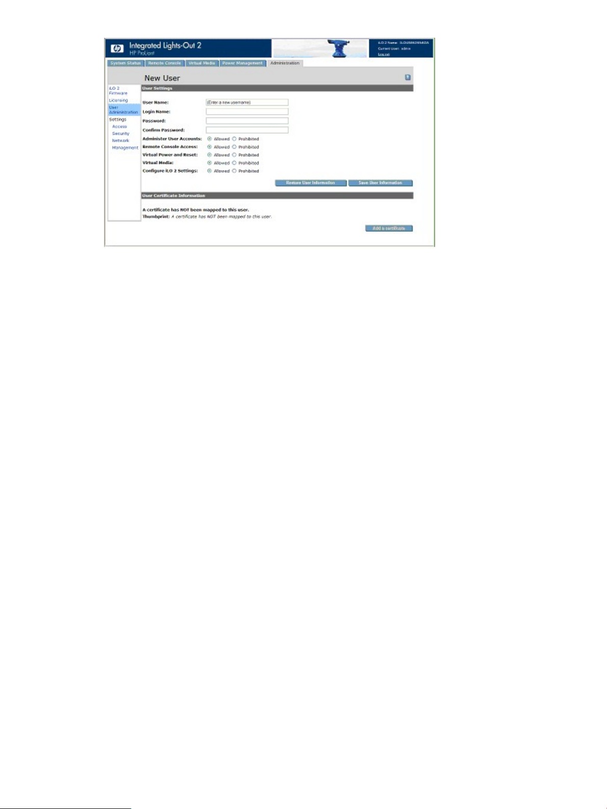
5. Complete the fields. The following options are available:
• User Name appears in the user list and on the home page. It is not necessarily the same
as the Login name. The maximum length for a User Name is 39 characters. The User
Name must use printable characters.
• Login Name is the name that you must use when logging in to iLO 2. The maximum length
for a login name is 39 characters. The login name can only use printable characters.
• Password and Confirm Password fields set and confirm the password that is used when
logging in to iLO 2. The minimum length for a password is set in the Access Options page.
The maximum length for a password is 39 characters. Enter the password twice for
verification.
• Administer User Accounts is a user privilege that allows you to add, modify, and delete
local iLO 2 user accounts. Administer User Accounts also allows you to alter privileges
for all users, including granting all permissions to yourself. Without this privilege, you
can only view your own settings and change your own password.
• Remote Console Access is a user privilege that allows you to remotely access the host
system Remote Console and Remote Serial Console, including video, keyboard and mouse
control. You are still required to have access to the remote system to use this capability.
• Virtual Power and Reset is a user privilege that allows you to power-cycle or reset the
host platform. Any of these activities interrupts the availability of the system. You can also
diagnose the system using the virtual NMI button.
• Virtual Media is a user privilege that allows you to use virtual media on the host platform.
• Configure iLO 2 Settings is a privilege that allows you to configure most iLO 2 settings,
• User Certificate Information maps a certificate to a user. User certificates are only required
30 Configuring iLO 2
including security settings. Configure iLO 2 Settings enables you to remotely update iLO
2 firmware. It does not include user account administration. These settings rarely change.
After correctly configuring iLO 2, revoking this privilege from all users prevents
reconfiguration. A user with the Administer User Accounts privilege can enable or disable
this privilege. If iLO 2 RBSU is enabled, you can also reconfigure iLO 2.
for two-factor authentication. If a certificate is not mapped to the user account, then the
following message displays A certificate has NOT been mapped to this
user, along with the Add a Certificate button. Click this button to map a certificate to
the user. After a certificate is mapped to the user account, a 40-digit thumbprint of the
certificate appears, along with the Remove this Certificate button, which can be used to
remove the certificate. If Two-Factor Authentication is enabled, map a different certificate
Page 31

to each user. A user who presents a certificate when connecting to iLO 2 is authenticated
as the user to whom the certificate is mapped. Two-Factor Authentication must be enabled
to authenticate using a certificate.
6. When the user profile is complete, return to the User Administration screen by clicking Save
User Information. To clear the user profile while entering a new user, click Restore User
Information.
Viewing or modifying existing user settings
1. Log in to iLO 2 using an account that has the Administer User Accounts privilege.
You must have the Administer User Accounts privilege to manage other users on iLO 2. All
users can change their own password using the View/Modify User feature.
2. Click Administration>User Administration, and select the name of the user whose information
you want to modify.
3. Click View/Modify.
4. Change user information as required.
5. After changing the fields, return to the User Administration screen by clicking Save User
Information. To recover the original user information, click Restore User Information. All
changes made to the profile are discarded.
Deleting a user
NOTE: Only users with the Administer User Accounts privilege can manage other users on iLO
2.
To delete existing user information:
1. Log in to iLO 2 using an account that has the Administer User Accounts privilege.
2. Click Administration.
3. Click User Administration and select from the list the name of the user whose information you
want to change.
4. Click Delete User.
A pop-up window displays:
Are you sure you want to delete the selected user?
5. Click OK.
User administration 31
Page 32
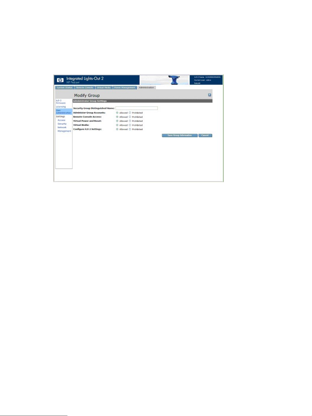
Group administration
The iLO 2 firmware enables you to view iLO 2 groups and modify settings for those groups. You
must have the Administer Directory Groups privilege. To view or modify a group:
1. Click Administration>User Administration>Group Accounts.
2. Select the group, and click View/Modify Group. The Modify Group page appears.
Click Cancel to return to the Group Administration page.
The following settings are available:
• Security Group Distinguished Name is the distinguished name of a group within the directory.
All members of this group are granted the privileges set for the group. The group specified in
the Security Group Distinguished Name must exist within the directory, and users who need
access to iLO 2 must be members of this group. Complete this field with a Distinguished Name
from the directory (for example, CN=Group1,OU=Managed Groups, DC=domain,
DC=extension).
• Administer Group Accounts enables users who belong to this group to alter privileges for any
group.
• Remote Console Access enables you to remotely access the host system Remote Console,
including the Remote Serial Console. You must have access to the remote system to use this
capability.
• Virtual Power and Reset enables you to power cycle or reset the host platform. These activities
interrupt the availability of the system. If selected, this option also allows you to diagnose the
system using the virtual NMI button.
• Virtual Media enables you to use virtual media on the host platform.
• Configure iLO 2 Settings enables you to configure most iLO 2 settings, including security
settings. If selected, you can remotely update iLO 2 firmware. This setting does not include
group account administration. These settings rarely change.
After iLO 2 is correctly configured, revoking this privilege from all groups prevents
reconfiguration. Users with the Administer Group Accounts privilege can enable or disable
this privilege. The iLO 2 firmware can also be reconfigured if iLO 2 RBSU is enabled.
To save updated information, click Save Group Information, or to discard changes and return to
the Group Administration page, click Cancel.
32 Configuring iLO 2
Page 33

Configuring iLO 2 access
The iLO 2 firmware enables you to configure which services are enabled on iLO 2 and user access
to iLO 2. To configure iLO 2 services options, click Administration>Access. The Services page (tab)
appears. To configure iLO 2 access options), click Administration>Access>Options (tab). You must
have the Configure iLO 2 Settings privilege to modify iLO 2 services and access options. For more
information, see “Access options” (page 38).
Services options
The Services tab enables you to select which services you want to enable on iLO 2, including SSH,
SSL, Remote Console, Telnet, and Terminal Services. The Services tab also enables you to set the
ports for each selected option. Settings on the Services page apply to all iLO 2 users. You must
have the Configure iLO 2 Settings privilege to modify settings on this page.
To access Services, click Administration>Access>Services. Click Apply to save updated information.
You must restart iLO 2 before any changes take effect. If any changes have been made to enable
or disable Lights-Out functionality, clicking Apply terminates your browser connection and restarts
iLO 2. You must wait at least 30 seconds before attempting to reestablish a connection.
The Services tab includes the following settings:
DescriptionDefault valueParameter
EnabledSecure Shell (SSH) Access
22Secure shell (SSH) Port
This setting enables you to specify whether the SSH feature on
the iLO 2 is enabled or disabled.
This setting enables you to configure the iLO 2 SSH port to be
used for SSH communications.
Configuring iLO 2 access 33
Page 34

DescriptionDefault valueParameter
DisabledTelnet Access
23Remote Console/Telnet Port
80Web Server Non-SSL Port
443Web Server SSL Port
DisabledTerminal Services Passthrough
This setting enables you to connect a Telnet client to the Remote
Console/Telnet port, providing access to the iLO 2 CLP. The
following settings are valid:
• Enabled – iLO 2 enables Telnet clients to connect to the
Remote Console/Telnet port. Network port scanners can
detect that iLO 2 is listening on this port. Unencrypted
communication is allowed between the iLO 2 CLP and Telnet
clients.
• Disabled – iLO 2 does not allow Telnet clients to connect to
the Remote Console/Telnet port. Network port scanners will
not normally detect if this port is open on iLO 2. iLO 2 listens
on this port for a few seconds when the Remote Console is
opened, but Telnet connections are not accepted.
Communication between the iLO 2 and Remote Console is
always encrypted.
This setting enables you to specify which port the iLO 2 Remote
Console uses for remote console communications.
This setting enables you to specify which port the embedded
web server in iLO 2 uses for unencrypted communications.
This setting enables you to specify which port the embedded
web server in iLO 2 uses for encrypted communications.
This setting enables you to control the ability to support a
connection through iLO 2 between a Microsoft Terminal Services
client and Terminal Services server running on the host. The
following settings are valid:
• Automatic – When remote console is started, the Terminal
Services client is launched.
• Enabled – The passthrough feature is enabled and can
connect the Terminal Services client directly to the iLO 2
without logging-into the iLO 2.
• Disabled – The passthrough feature is off.
3389Terminal Services Port
EnabledVirtual Media
17988Virtual Media Port
9300Shared Remote Console Port
17990Console Replay Port
This setting enables you to specify the Terminal Services Port
that the iLO 2 uses for encrypted communications with Terminal
Services passthrough software on the server. If the Terminal
Services port is configured to anything other than the default,
you must manually change the port number.
This setting enables you to specify whether the virtual media
port on the iLO 2 is enabled or disabled. The following settings
are valid:
• Enabled – iLO 2 enables the Virtual media port.
• Disabled – iLO 2 disables the Virtual media port.
This setting enables you to specify the port for virtual media
support in iLO 2 communications.
This setting enables you to specify the Shared Remote Console
Port. The Shared Remote Console Port is opened on the client
to allow additional users to connect to remote console in a
peer-to-peer fashion. This port is only open when Shared Remote
Console is in use.
This setting enables you to specify the Console Replay Port. The
Console Replay Port is opened on the client to enable the
transfer of internal capture buffers to the client for replay. This
34 Configuring iLO 2
Page 35

DescriptionDefault valueParameter
port is only open when a capture buffer is being transferred to
the client.
3002Raw Serial Data Port
Terminal Services Passthrough option
Terminal Services is provided by the Microsoft Windows operating systems. The iLO 2 Terminal
Services Passthrough option provides a connection between the Terminal Services server on the
host system and the Terminal Services client on the client system. When the Terminal Services
Passthrough option is enabled, the iLO 2 firmware enables a socket, listening by default on port
3389. All data received from Terminal Services on this port is forwarded to the server and all data
Terminal Services receives from the server is forwarded back to the socket. The iLO 2 firmware
reads anything received on this port as an RDP packet. RDP packets are exchanged between the
iLO 2 firmware and the server Terminal Services (RDP) server through the local host address on
the server. The service provided facilitates communications between the iLO 2 firmware and the
RDP server. The RDP server interprets the service as an established external RDP connection. For
more information on RDP services, see “Windows RDP Passthrough service” (page 36).
A Terminal Services session provides a performance-enhanced view of the host system console.
When the operating system is unavailable (or the Terminal Services server or client is unavailable),
the traditional iLO 2 Remote Console provides a view of the host system console. For more
information on Remote Console and Terminal Services, see “Remote Console and Terminal Services
clients” (page 37).
To configure the Terminal Services Passthrough option, see the “Terminal Services client
requirements” (page 35) and “Terminal Services Passthrough installation” (page 36).
This setting specifies the Raw Serial Data port address. The Raw
Serial Data port is only open while the WiLODbg.exe utility is
being used to debug the host server remotely.
Terminal Services client requirements
The Terminal Services client is available on Microsoft Windows client machines running:
• Windows Server 2003
On Windows Server 2003 servers, the Terminal Services client and RDP connection is built-in.
The client is part of the operating system and is activated using Remote Desktop sharing. To
activate desktop sharing, select My Computer>Properties>Remote>Remote Desktop. The
Terminal Services client in Windows Server 2003 provides command-line options and seamless
launches from the Remote Console applet.
• Windows Server 2008
On Windows Server 2008 servers, the Terminal Services client and RDP connection is built-in.
The client is part of the operating system and is activated using Remote Desktop sharing. To
activate desktop sharing, select My Computer>Properties>Remote>Remote Desktop. The
Terminal Services client in Windows Server 2008 provides command-line options and seamless
launches from the Remote Console applet.
• Windows XP
On Windows XP servers, the Terminal Services client and RDP connection is built in. The client
is part of the operating system and is activated using Remote Desktop sharing. To activate
desktop sharing, select Start>Programs>Accessories>Communications>Remote Desktop. The
Terminal Services client in Windows XP provides command-line options and launches from
the remote console applet.
Configuring iLO 2 access 35
Page 36

Windows RDP Passthrough service
To use the iLO 2 Terminal Services Passthrough feature, you must install a passthrough service on
the host system. This service displays the name of the iLO 2 Proxy in the host list of available
services. The service utilizes Microsoft .NET framework security and reliability. After the service is
started, the service polls iLO 2 to detect if an RDP connection with the client is established. If an
RDP connection with the client is established, the service establishes a TCP connection with local
host and begins exchanging packets. The port used to communicate with the local host is read
from the Windows registry at:
HKEY_LOCAL_MACHINE\System\CurrentControlSet\Control\TerminalServer\
Wds\rdpwd\Tds\tcp\PortNumber
The port is typically port 3389.
Terminal Services Passthrough installation
The following section describes how to install Terminal Services Passthrough on Windows Server
2008, Windows Server 2003, and Microsoft Windows XP.
• Windows Server 2003 and Windows Server 2008
Windows servers require Microsoft .NET Framework to support the use of iLO 2 Terminal
Services. The Terminal Services Passthrough service and the iLO 2 Management Interface
driver for Windows Server 2008 and Windows Server 2003 must be installed on the server
that has the iLO 2.
1. Install the iLO 2 Management Interface driver.
2. Install the passthrough service. To install the service, launch the component installer and
follow the directions in the installation wizard.
If the service is already installed, then you must manually restart or reboot the server when
the driver is installed.
3. Activate the Terminal Services client.
On Windows Server 2003 and Windows Server 2008, you can activate Remote Desktop
sharing by clicking the Remote tab under My Computer and Properties.
If the iLO 2 installation is complete, and if iLO 2 Terminal Services passthrough option is set
to automatic, then Terminal Services launches when the installation is complete.
• Microsoft Windows XP
On Windows XP, the Remote Desktop Connection is built-in and has no other installation
requirements.
Errors that occur during installation and execution of the passthrough service are logged in the
server Application Event Log. You can remove the passthrough service using Add or Remove
Programs in the Control Panel.
Enabling the Terminal Services Passthrough option
By default, the Terminal Services Passthrough feature is disabled and can be enabled on the
Administration>Access>Services page. The Terminal Services button in the Remote Console is
deactivated until the Terminal Services passthrough feature is enabled.
To use of the Terminal Services Passthrough feature, install the latest Lights-Out Management
Interface Driver and then install Terminal Services passthrough service for Microsoft Windows on
the server.
When the Terminal Services Passthrough option is set to Enabled or Automatic on the
Administration>Access>Services page and the Terminal Services Client is installed on the Windows
client (installs by default on Windows XP), the Terminal Services button is enabled. When you click
the Terminal Services button, the applet tries to launch the Terminal Services, even if the server is
not running a Windows operating system.
36 Configuring iLO 2
Page 37

You must comply with Microsoft license requirements which are the same as connecting through
the server's NIC. For instance, when set for administrative access, Terminal Services does not allow
more than two connections, regardless of whether the connections are through the server's NIC,
or iLO 2, or both.
Terminal Services warning message
Terminals Services users operating on Windows 2003 Server might notice the following when
using the Terminal Services passthrough feature of iLO 2. If a Terminal Services session is established
through iLO 2 and a second Terminal Services session is established by a Windows administrator
(Console mode), the first Terminal Services session is disconnected. However, the first Terminal
Services session does not receive the warning message indicating the disconnection until
approximately one minute later. During this one-minute period, the first Terminal Services session
is available or active. This is normal behavior, but it is different than the behavior observed when
both Terminal Services sessions are established by Windows administrators. In that case, the
warning message is received by the first Terminal Services session immediately.
Terminal Services Passthrough option display
The iLO 2 firmware might not accurately display the Terminal Services Passthrough option. The
Terminal Services Passthrough option might appear active even if the operating system is not
Terminal Services enabled (for example, if the host operating system is Linux, which does not
support Terminal Services operation).
Remote Console and Terminal Services clients
Using the management network connection to the iLO 2, an iLO 2 Remote Console session can
be used to display a Terminal Services session to the host. When the iLO 2 Remote Console applet
runs, it launches the Terminal Services client based on user preference. The Sun JVM must be
installed to obtain full functionality of this feature. If the Sun JVM is not installed, then the Remote
Console cannot automatically launch the Terminal Services client.
If Terminal Services passthrough is enabled, and the Terminal Services server is available, switching
between iLO 2 Remote Console and the Terminal Services client will be seamless as the server
progresses from pre-operating system environment to operating system-running environment, to
operating system-not available environment. The seamless operation is available as long as the
Terminal Services client is not started before Remote Console is available. If Remote Console is
available and the Terminal Services client is available, Remote Console will start the Terminal
Services client when appropriate.
When using the Terminal Services passthrough option with Windows Server 2003 and Windows
Server 2008, a 30-second delay occurs after the CTRL-ALT-DEL dialog box appears before the
Terminal Services client launches. The 30-second delay represents how long it takes for the service
to connect to the RDP client running on the server. If the server is rebooted from the Terminal Services
client, the Remote Console screen turns grey or black for up to one minute while iLO 2 determines
that the Terminal Services server is no longer available.
If Terminal Services mode is set to Enabled, but you want to use the Remote Console, then launch
the Terminal Services client directly from the Terminal Services client menu. Launching directly from
the client menu enables simultaneous use of the Terminal Services client and the Remote Console.
Terminal Services can be disabled or enabled at any time. Changing the Terminal Services
configuration causes the iLO 2 firmware to reset. Resetting the iLO 2 firmware interrupts any open
connections to iLO 2.
When the Terminal Services client is launched by the Remote Console, Remote Console goes into
a sleep mode to avoid consuming CPU bandwidth. Remote Console still listens to the Remote
Console default port 23 for any commands from iLO 2.
The iLO 2 firmware passes through only one Terminal Services connection at a time. Terminal
Services has a limit of two concurrent sessions.
Configuring iLO 2 access 37
Page 38

The Remote Console activates and becomes available if the Remote Console is in sleep mode and
the Terminal Services client is interrupted by any of the following events:
• The Terminal Services client is closed by the user.
• The Windows operating system is shut down.
• The Windows operating system locks up.
Terminal Services troubleshooting
To resolve issues with iLO 2 Terminal Services Passthrough:
1. Verify that Terminal Services is enabled on the host by selecting
My Computer>Properties>Remote>Remote Desktop.
2. Verify that the iLO 2 passthrough configuration is enabled or automatic in the iLO 2 Global
Settings.
3. Verify that iLO Advanced Pack is licensed.
4. Verify that the iLO 2 Management Interface Driver is installed on the host. To verify the driver,
select My Computer>Properties>Hardware>Device Manager>Multifunction Adapters.
5. Verify that the Terminal Services passthrough service and iLO 2 Proxy are installed and running
on the host. To verify these services, select Control Panel>Administrative Tools>Services and
attempting to restart the service.
6. Verify that the Application Event Log is not full.
The Terminal Services passthrough service might experience start-up issues when the operating
system Application Event Log is full. To view the event log, select Computer
Management>System Tools>Event Viewer>Application.
7. Verify that the Terminal Services port assignment is correct.
8. Verify that the Terminal Services client, mstsc.exe is located in \WINDOWS\SYSTEM32.
If not, set the passthrough configuration to Enabled, and manually activate the terminal services
client.
Access options
The iLO 2 firmware enables you to modify iLO 2 access, including connection idle time, iLO 2
functionality, iLO 2 RBSU, login requirements, CLI parameters, minimum password length, and
server name. Settings on the Access Options page apply to all iLO 2 users. You must have the
Configure iLO 2 Settings privilege to modify settings on this page.
To view or modify iLO 2 access, click Administration>Access>Options and click Apply to save any
updated information. You must restart iLO 2 before your updates take effect. If any changes enable
or disable Lights-Out functionality, click Apply to terminate your browser connection and restart
iLO 2. You must wait at least 30 seconds before attempting to reestablish a connection.
38 Configuring iLO 2
Page 39

The Options tab includes the following.
DescriptionsDefault valueParameter
(minutes)
Setup Utility
RBSU
POST
30 minutesIdle Connection Timeout
EnabledLights-Out Functionality
EnablediLO 2 ROM-Based
DisabledRequire Login for iLO 2
DisabledShow iLO 2 during
This setting specifies the interval of user inactivity, in minutes, before
the web server and Remote Console session automatically terminate.
The following settings are valid: 15, 30, 60, 120 minutes, or 0
(infinite). The infinite timeout value does not log out inactive users.
This setting enables connection to iLO 2. If disabled, all connections
to iLO 2 are prevented.
The iLO 2 10/100 network and communications with operating system
drivers are turned off if Lights-Out functionality is disabled. The iLO 2
Diagnostic Port for an HP ProLiant BL p Class server is also disabled.
If iLO 2 functionality is disabled (including the iLO 2 Diagnostic Port),
you must use the server Security Override Switch to enable iLO 2. See
your server documentation to locate the Security Override Switch and
set it to Override. Power the server on and use the iLO 2 RBSU to set
Lights-Out Functionality to Enabled.
This setting enables or disables the iLO 2 ROM-Based Setup Utility.
Normally, the iLO2 Option ROM prompts you to press F8 to enter
RBSU, but if iLO 2 is disabled or iLO 2 RBSU is disabled, the RBSU
prompt is bypassed.
This setting enables RBSU access with or without a user-credentials
challenge. If this setting is Enabled and you press F8 during POST to
enter iLO 2 RBSU, a login dialog box appears.
This setting enables the display of the iLO 2 network IP address during
the host server POST process.
prompt
DisablediLO 2 Enhanced CLI
The SMASH CLP can be enhanced by including the server name in the
“hpiLO” prompt. This button enables the user to enable or disable the
enhanced CLI prompt feature. By default, this feature is disabled. The
following settings are valid:
• Enabled – iLO 2 enables the enhanced CLI prompt feature.
• Disabled – iLO 2 disables the enhanced CLI prompt.
Configuring iLO 2 access 39
Page 40

DescriptionsDefault valueParameter
Serial Command Line
Interface Status
Interface Speed
Length
Server Name
Authentication Failure
Logging
Enabled-Authentication
Required
9600Serial Command Line
8Minimum Password
Enabled-Every 3rd
Failure
This setting enables you to change the login model of the CLI feature
through the serial port. The following settings are valid:
• Enabled – Authentication Required
• Enabled – No Authentication
• Disabled
This setting enables you to use the serial port to change the speed of
the serial port for the CLI feature. The following speeds (in bits/s) are
valid: 9600, 19200, 38400, 57600, and 115200. The serial port
configuration must be set to No parity, 8 data bits, and 1 stop bit
(N/8/1) for proper operation. The serial port speed that is set by this
parameter must match the speed of the serial port set in the System
ROM RBSU setup.
This setting specifies the minimum number of characters allowed when
a user password is set or changed. The character length can be set at
a value from 0 to 39.
This setting enables you to specify the host server name. This value is
assigned when using HP ProLiant Management Agents. If you do not
use the agents and the host unnamed message appears, you can
change it here. If the agents are running, the value you assign can be
overwritten.
To force the browser to refresh, save this setting, and press F5.
This setting enables you to configure logging criteria for failed
authentications. All login types are supported and every login type
works independently. The following are valid settings:
• Enabled-Every Failure – A failed login log entry is recorded after
every failed login attempt.
• Enabled-Every 2nd Failure – A failed login log entry is recorded
after every second failed login attempt.
• Enabled-Every 3rd Failure – A failed login log entry is recorded
after every third failed login attempt.
• Enabled-Every 5th Failure – A failed login log entry is recorded after
every fifth failed login attempt.
• Disabled – No failed login log entry is recorded.
When logging in to iLO 2 with Telnet or SSH clients, the number of login name and password
prompts offered by iLO 2 matches the value of the Authentication Failure Logging parameter (or
3 when it is disabled.) However, the number of prompts might also be affected by your Telnet and
SSH client configurations. Telnet and SSH logins also implement delays after login failure. During
the delay, login is disabled so no login failure occurs. As an example, to generate an SSH
authentication failure log with a default value (for instance, Enabled-Every 3rd Failure), three
consecutive login failures occur as follows (assuming the SSH client is configured with the number
of password prompts >= 3):
1. Run the SSH client and log in with an incorrect login name and password. You will receive
three password prompts. After the third incorrect password, the connection terminates, and
the first login failure is recorded. The SSH login failure counter is set to 1.
2. Run the SSH client until receiving the login prompt. Log in with an incorrect login name and
password. You will receive three password prompts. After the third incorrect password, the
40 Configuring iLO 2
DisabledVirtual Serial Port Log
This setting enables you to capture the serial port output messages into
a circular log buffer. The following settings are valid:
• Enabled - Virtual serial Port log feature is enabled.
• Disabled - Virtual serial Port log feature is disabled.
Page 41

connection terminates, and the second login failure is recorded. The SSH login failure counter
is set to 2.
3. Run the SSH client until receiving the login prompt. Log in with an incorrect login name and
password. You will receive three password prompts. After the third incorrect password, the
connection terminates and the third login failure is recorded. The SSH login failure counter is
set to 3.
At this point, iLO 2 firmware records an SSH login failure log entry and sets the SSH login failure
counter to 0.
iLO 2 Remote Console and Remote Serial Console access
For iLO 2 Remote Console recommended client settings, server settings, optimizing mouse support,
and Remote Serial Console settings, see “iLO 2 Remote Console” (page 80).
Security
The iLO 2 firmware enables you to customize iLO 2 security settings. To access iLO 2 security
settings, select Administration>Security. iLO 2 security options include:
• “SSH key administration” (page 44)
• “SSL certificate administration” (page 45)
• “Two-factor authentication” (page 46)
• “Directory settings” (page 51)
• “Encryption” (page 53)
• “HP SIM single sign-on (SSO)” (page 55)
• “Remote Console Computer Lock” (page 58)
iLO 2 security options enables iLO 2 to provide the following security features:
• User-defined TCP/IP ports
• User actions logged in the iLO 2 Event Log
• Progressive delays for failed login attempts
• Support for X.509 CA signed certificates
• Support for securing RBSU
• Encrypted communication using:
SSH key administration—
— SSL certificate administration
• Support for optional LDAP-based directory services
Some of these options are licensed features. To verify your available options, see “Licensing” (page
26).
General security guidelines
The following are general guidelines concerning security for iLO 2:
• For maximum security, iLO 2 must be set up on a separate management network.
• The iLO 2 firmware must not be connected directly to the Internet.
• A 128-bit cipher strength browser must be used.
Security 41
Page 42

Password guidelines
The following is a list of recommended password guidelines. Passwords must:
• Never be written down or recorded
• Never be shared with others
• Not be words generally found in a dictionary, or easy to guess words, such as the company
name, product names, the user's name, or the user's User ID
• Include at least three of the four following characteristics:
At least one numeric character◦
◦ At least one special character
◦ At least one lowercase character
◦ At least one uppercase character
Passwords issued for a temporary user ID, password reset, or a locked-out user ID must also conform
to these standards. Each password must be a minimum length of zero characters and a maximum
length of 39 characters. The default minimum length is set to eight characters. Setting the minimum
password length to fewer than eight characters is not recommended unless you have a physically
secure management network that does not extend outside the secure data center.
Securing RBSU
iLO 2 RBSU enables you to view and modify the iLO 2 configuration. RBSU access settings can
be configured using RBSU, a web browser, RIBCL scripts, or the iLO 2 Security Override Switch.
For more information, see “Access options” (page 38). RBSU has three levels of security:
• RBSU Login Not Required (default)
Anyone with access to the host during POST can enter the iLO 2 RBSU to view and modify
configuration settings. This is an acceptable setting if host access is controlled.
• RBSU Login Required (more secure)
If RBSU login is required, then the active configuration menus are controlled by the authenticated
user's access rights.
• RBSU Disabled (most secure)
If iLO 2 RBSU is disabled, user access is prohibited. This prevents modification using the RBSU
interface.
iLO 2 Security Override Switch administration
The iLO 2 Security Override Switch allows the administrator full access to the iLO 2 processor.
This access might be necessary for any of the following conditions:
• The iLO 2 firmware must be re-enabled after it has been disabled.
• All user accounts with the Administer User Accounts privilege have been locked out.
• A bad configuration keeps the iLO 2 from displaying on the network and RBSU has been
disabled.
• The boot block must be flashed.
Ramifications of setting the Security Override Switch include:
• All security authorization checks are disabled while the switch is set.
• The iLO 2 firmware RBSU runs if the host server is reset.
• The iLO 2 firmware is not disabled and might display on the network as configured.
42 Configuring iLO 2
Page 43

• The iLO 2 firmware, if disabled while the Security Override Switch is set, does not log the
user out and complete the disable process until the power is cycled on the server.
• The boot block is exposed for programming.
NOTE: The iLO 2 Security Override Switch is located inside the server and cannot be accessed
without opening the server enclosure.
A warning message appears on iLO 2 browser pages indicating that the iLO 2 Security Override
Switch is currently in use. An iLO 2 log entry records the use of the iLO 2 Security Override Switch.
An SNMP alert can also be sent upon setting or clearing the iLO 2 Security Override Switch.
Setting the iLO 2 Security Override Switch also enables you to flash the iLO 2 boot block. HP does
not anticipate you needing to update the iLO 2 boot block. If an iLO 2 boot block update is
required, you must perform the update at the server, then and reset iLO 2. The boot block update
cannot be done remotely. The boot block is exposed until iLO 2 is reset. For maximum security,
HP recommends that you disconnect the iLO 2 from the network until you complete the reset.
To set the iLO 2 Security Override Switch:
1. Power off the server.
2. Set the switch.
3. Power on the server.
Reverse the procedure to clear the iLO 2 Security Override Switch.
Depending on the server, the iLO 2 Security Override Switch might be a single jumper or a specific
switch position on a dip switch panel. To access and locate the iLO 2 Security Override Switch,
see the server documentation. The iLO 2 Security Override Switch can also be located using the
diagrams on the server access panel.
Trusted Platform Module support
TPM is a hardware based system security feature. It is a computer chip that securely stores artifacts
used to authenticate the platform. These artifacts can include passwords, certificates, or encryption
keys. You can also use a TPM to store platform measurements to help ensure that the platform
remains trustworthy. iLO 2 provides support for the TPM mezzanine module in ProLiant 100, 300,
and 500 series servers.
On a supported system, iLO 2 decodes the TPM record and passes the configuration status to iLO
2, CLP, and XML interface. The System Status page displays the TPM configuration status. If the
host system or System ROM does not support TPM, TPM Status is not displayed in Status Summary
page. The Status Summary displays the following TPM status information:
• Not Present – A TPM module is not installed.
• Present – when:
A TPM module is installed but it is disabled.◦
◦ A TPM module is installed and enabled.
◦ A TPM module is installed, enabled, and Expansion ROM measuring is enabled. If
Expansion ROM measuring is enabled, the Update iLO 2 Firmware page displays a legal
warning message when you click Send firmware image.
User accounts and access
The iLO 2 firmware supports the configuration of up to 12 local user accounts. Each of these
accounts can be managed through the use of the following features:
• “Privileges” (page 44)
• “Login security” (page 44)
Security 43
Page 44

The iLO 2 firmware iLO 2 can be configured to use a directory to authenticate and authorize its
users. This configuration enables a virtually unlimited number of users, and easily scales to the
number of Lights-Out devices in an enterprise. Additionally, the directory provides a central point
of administration for Lights-Out devices and users, and the directory can enforce a stronger password
policy. iLO 2 enables you to use local users, directory users, or both.
Two configuration options are available:
• To use a directory that has been extended with HP Schema, see “Setting up HP schema
• To use the directory default schema (schema-free), see “Setting up Schema-free directory
Privileges
The iLO 2 firmware enables the administrator to control user account access to iLO 2 functions
through the use of privileges. When a user attempts to use a function, the iLO 2 system verifies
that the user has the privilege before the user is allowed to perform the function.
Each feature available through iLO 2 can be controlled through privileges, including Administer
User Accounts, Remote Console Access, Virtual Power and Reset, Virtual Media, and Configure
iLO 2 Settings. Privileges for each user can be configured on the User Administration page of the
Administration tab.
Login security
directory integration” (page 136).
integration” (page 132).
iLO 2 provides several login security features. After an initial failed login attempt, iLO 2 imposes
a delay of five seconds. After a second failed attempt, iLO 2 imposes a delay of 10 seconds. After
the third failed attempt, and any subsequent attempts, iLO 2 imposes a delay of 60 seconds. All
subsequent failed login attempts cycles through these values. An information page appears during
each delay. This continues until a valid login is completed. This feature assists in defending against
possible dictionary attacks against the browser login port.
The iLO 2 firmware saves a detailed log entry for failed login attempts, which imposes a delay of
60 seconds.
SSH key administration
The iLO 2 firmware enables you to authorize up to four SSH keys at one time on the SSH Key tab.
The SSH Key tab also displays the owner (if any keys are authorized) of each authorized SSH key.
Multiple keys can belong to a single user.
To add an authorized key to iLO 2, the public key path must be submitted to iLO 2. The key file
must contain the user name after the end of the key. iLO 2 associates each key with a local user
account. If the local account does not exist or if it is deleted, the key is invalid (the key is not listed
if the local account does not exist).
Alternatively, you can authorize SSH keys for an HP SIM server by running the mxagentconfig tool
from the HP SIM server and specifying the address and user credentials for iLO 2. See your HP
SIM documentation for more details.
To authorize a new key:
1. In the iLO 2 interface, click Administration>Security>SSH Key.
2. Click Browse, and locate the key file.
3. Click Authorize Key.
You can view or delete any previously authorized key by selecting the key, and clicking View
Selected Key or Delete Selected Key. The View Selected Key and Delete Selected Key buttons only
appear when SSH keys are installed.
44 Configuring iLO 2
Page 45

SSL certificate administration
The iLO 2 firmware enables you to create a certificate signing request (CSR) with custom subject
information or default settings, import a certificate, and view certificate administration information
associated with a stored certificate. Certificate information is encoded in the certificate by the CA
and is extracted by iLO 2.
By default, iLO 2 creates a self-signed certificate for use in SSL connections. This certificate enables
iLO 2 to work without any additional configuration steps. The security features of the iLO 2 can
be enhanced by importing a trusted certificate. For more information on certificates and certificate
services, see “Introduction to certificate services” (page 132) and “Installing certificate services”
(page 132).
To access certificate information, click Administration>Security>SSL Certificate. The SSL Certificate
tab displays the following information:
• The Issued To field lists the entity to which the certificate was issued.
• The Issued By field lists the CA that issued the certificate.
• The Valid From field lists the first date that the certificate is valid.
• The Valid Until field lists the date that the certificate will expire.
• The Serial Number field lists the serial number assigned to the certificate by the CA.
• The Domain Name button to choose between the fully qualified domain name and the
shortname as CSR Common Name (CN).
• The SSL Key Length button to choose between 2048 or 1024 bit private key length for CSR.
• The Customized CSR radio button to choose between CSR with custom or default subject fields.
• The Country field for configuring the CSR subject country name.
• The State or Province field for configuring the CSR subject state name.
• The Organization Name field for configuring the CSR subject organization name.
• The Organization Unit field for configuring the CSR subject organization unit name.
• The City or Locality field for configuring the CSR subject city or locality name.
• The Common Name field for configuring the CSR subject common name.
The following options are available on the SSL Certificate tab:
• Apply Button – When you click the Apply button, custom CSR data is validated and stored in
iLO2. During the certificate generation request, the stored CSR settings are used by iLO2.
• Create Certificate Request – Use this button to create a certificate request. When you click
this button, a CR is created (in PKCS #10 format) that can be sent to a CA. This certificate
request is Base64-encoded. A CA processes this request and returns a response (X.509
certificate) that can be imported into iLO 2.
The CR contains a public/private key pair that validates communications between the client
browser and iLO 2. The generated CR is held in memory until a new CR is generated, iLO 2
is reset, or a certificate is imported by the generation process. You can generate the CR and
copy it to the client clipboard, leave the iLO 2 website to retrieve the certificate, and then
return to import the certificate.
When submitting the request to the CA, be sure to perform the following tasks:
1. Use the iLO 2 name as listed on the System Status screen as the URL for the server.
2. Request that the certificate is generated in the RAW format.
3. Include the Begin and End certificate lines.
Every time you click Create Certificate Request, a new certificate request is generated, even
though the iLO 2 name is the same. Generally SSL keys pairs are pre-generated. The CSR is
Security 45
Page 46

generated immediately on clicking the Create Certificate Request button. However, the
certificate request generation button is grayed out while the key generation is in progress. In
this scenario, you can close all active Remote Console sessions and try again later (around
2 minutes for a 1024-bit key, and 10 minutes for 2048-bit key).
• Import Certificate – Use this button when you are returning to the Certificate Administration
page with a certificate to import. Click Import Certificate to go directly to the Certificate Import
screen without generating a new CR. A certificate only works with the keys generated for the
original CR from which the certificate was generated. If iLO 2 has been reset, or another CR
was generated since the original CR was submitted to a CA, then a new CR must be generated
and submitted to the CA.
You can customize and create a CR or import an existing certificate using RIBCL XML commands.
These commands enable you to script and automate certificate deployment on iLO 2 servers instead
of manually deploying certificates through the browser interface. For more information, see HP
Integrated Lights-Out Management Processor Scripting and Command Line Resource Guide at
http://h20000.www2.hp.com/bizsupport/TechSupport/DocumentIndex.jsp?
contentType=SupportManual&lang=en&cc=us&docIndexId=64179&taskId=135&
prodTypeId=18964&prodSeriesId=1146658.
Two-factor authentication
Access to iLO 2 requires user authentication. This firmware release provides an enhanced
authentication scheme for iLO 2 using two factors of authentication: a password or PIN, and a
private key for a digital certificate. Using two-factor authentication requires that you verify your
identity by providing both factors. You can store your digital certificates and private keys wherever
you choose, for example, on a smart card, USB token, or hard drive.
The Two-Factor Authentication tab enables you to configure security settings and review, import,
or delete a trusted CA certificate. The Two-Factor Authentication Enforcement setting controls
whether two-factor authentication is used for user authentication during login. To require two-factor
authentication, click Enabled. To turn off the two-factor authentication requirement and allow login
with user name and password only, click Disabled. You cannot change the setting to Enabled if a
trusted CA certificate is not configured. To provide the necessary security, the following configuration
changes are made when two-factor authentication is enabled:
• Telnet Access: Disabled
• Secure Shell (SSH) Access: Disabled
• Serial Command Line Interface Status: Disabled
If Telnet, SSH, or Serial CLI access is required, re-enable these settings after two-factor authentication
is enabled. However, because these access methods do not provide a means of two-factor
authentication, only a single factor is required to access iLO 2 with Telnet, SSH, or Serial CLI.
When two-factor authentication is enabled, access by the CPQLOCFG utility is disabled because
CPQLOCFG does not meet all authentication requirements. However, the HPONCFG utility works
because administrator privileges on the host system are required to execute the utility.
A trusted CA certificate is required for two-factor authentication to function. You cannot change
the Two-Factor Authentication Enforcement setting to Enabled if a trusted CA certificate is not
configured. Also, you must map a client certificate to a local user account if local user accounts
are used. If iLO 2 is using directory authentication, client certificate mapping to local user accounts
is optional.
To change two-factor authentication security settings for iLO 2:
1. Log in to iLO 2 with an account that has the Configure iLO 2 Settings privilege.
2. Click Administration>Security>Two-Factor Authentication.
3. Change the settings by entering your selections in the fields.
4. To save the changes, click Applys.
46 Configuring iLO 2
Page 47

The Certificate Revocation Checking setting controls whether iLO 2 uses the certificate CRL
distribution points attribute to download the latest CRL and verify revocation of the client certificate.
If the client certificate is contained in the CRL, or if you cannot download the CRL, access is denied.
The CRL distribution point must be available and accessible to iLO 2 when Certificate Revocation
Checking is set to Yes.
The Certificate Owner Field setting specifies which attribute of the client certificate to use when
authenticating with the directory. Only use the Certificate Owner Field setting if directory
authentication is enabled. Configuration of the Certificate Owner Field depends on the version of
directory support used, the directory configuration, and the certificate issuance policy of your
organization. If SAN is specified, iLO 2 extracts the User Principle Name from the Subject Alternative
Name attribute and then uses the User Principle Name when authenticating with the directory (for
example, username@domain.extension). For example, if the subject name is /DC=com/DC=domain/
OU=organization/CN=user, iLO 2 will derive
CN=user,OU=organization,DC=domain,DC=com.
Setting up two-factor authentication for the first time
When setting up two-factor authentication for the first time, you can use either local user accounts
or directory user accounts. For more information on two-factor authentication settings, see “Two-factor
authentication” (page 46).
Setting up local user accounts
1. Obtain the public certificate from the CA that issues user certificates or smart cards in your
organization.
2. Export the certificate in Base64-encoded format to a file on your desktop (for example,
CAcert.txt).
3. Obtain the public certificate of the user who needs access to iLO 2.
4. Export the certificate in Base64-encoded format to a file on your desktop (for example,
Usercert.txt).
5. Open the file CAcert.txt in Notepad, select all of the text, and copy it by pressing the Ctrl+C
keys.
6. Log in to iLO 2, and browse to the Two-Factor Authentication Settings page.
7. Click Import Trusted CA Certificate. The Import Root CA Certificate page appears.
8. Click inside the white text area so that your cursor is in the text area, and paste the contents
of the clipboard by pressing the Ctrl+V keys.
9. Click Import Root CA Certificate. The Two-Factor Authentication Settings page appears again
with information displayed under Trusted CA Certificate Information.
10. From your desktop, open the file for the user certificate in Notepad, select all the text, and
copy the text to the clipboard by pressing the Ctrl+C keys.
11. Browse to the User Administration page on iLO 2, and select the user for which you have
obtained a public certificate or create a new user.
12. Click View/Modify.
13. Click Add a certificate.
14. Click inside the white text area so that your cursor is in the text area, and paste the contents
of the clipboard by pressing the CTRL+V keys.
15. Click Add User Certificate. The Modify User page appears again with a 40-digit number in
the Thumbprint field. You can compare the number to the thumbprint displayed for the certificate
by using Microsoft Certificate Viewer.
16. Browse to the Two-Factor Authentication Settings page.
17. Select Enabled for the Two-Factor Authentication option.
18. Select Disabled for the Certificate Revocation Checking option. This value is the default.
Security 47
Page 48

19. Click Apply to reset iLO 2. When iLO 2 attempts to go to the login page again, the browser
displays the Client Authentication page with a list of certificates that are available to the
system.
If the user certificate is not registered on the client machine, you will not see it in the list. The
user certificate must be registered on the client system before you can use it. If there are no
client certificates on the client system you might not see the Client Authentication page and
instead see a Page cannot be displayed error. To resolve the error, the client certificate must
be registered on the client machine. For more information on exporting and registering client
certificates, see the documentation for your smart card or contact your certificate authority.
20. Select the certificate that was added to the user in iLO 2. Click OK.
21. If prompted to do so, insert your smart card, or enter your PIN or password.
After completing the authentication process, you have access to iLO 2.
Setting up directory user accounts
1. Obtain the public certificate from the CA that issues user certificates or smart cards in your
organization.
2. Export the certificate in Base64-encoded format to a file on your desktop (for example,
CAcert.txt).
3. Open the file in Notepad, select all the text, and copy the contents to the clipboard by pressing
the Ctrl+C keys.
4. Log in to iLO 2, and browse to the Two-Factor Authentication Settings page.
5. Click Import Trusted CA Certificate. Another page appears.
6. Click inside the white text area so that your cursor is in the text area, and paste the contents
of the clipboard by pressing the Ctrl+V keys.
7. Click Import Root CA Certificate. The Two-Factor Authentication Settings page appears again
with information displayed under Trusted CA Certificate Information.
8. Change Enforce Two-Factor authentication to Yes.
9. Change Certificate Revocation Checking to No (default).
10. Change Certificate Owner Field to SAN. For more information, see “Two-factor authentication”
(page 46).
11. Click Apply. iLO 2 is reset. When iLO 2 attempts to go to the login page again, the browser
displays the Client Authentication page with a list of certificates that are available to the
system.
12. Select the certificate added to the user in iLO 2. Click OK.
13. If prompted to do so, insert your smart card, or enter your PIN or password. The login page
appears with the e-mail address for the user in the Directory User field. You cannot change
the Directory User field.
14. Enter the password for the directory user. Click Login.
After completing the authentication process, you have access to iLO 2. For more information on
configuring directory users and privileges, see “Directory settings” (page 51).
Setting up a user for two-factor authentication
To authenticate a user with a local iLO 2 account, a certificate must be associated with the user's
local user name. On the Administration>Modify User page, if a certificate has been mapped to
the user, a thumbprint (an SHA1 hash of the certificate) appears with a button that removes the
certificate. If a certificate has not been mapped to the user, the following message displays, as
well as a button that starts the certificate import process:
Thumbprint: A certificate has NOT been mapped to this user
To set up a user for two-factor authentication and add a user certificate:
1. Log in to iLO 2 using an account that has the Configure iLO 2 Settings privilege.
2. Click Administration>User Administration. Select a user.
48 Configuring iLO 2
Page 49

3. Click View/Modify.
4. Under the User Certificate Information section, click Add a certificate.
5. On the Map User Certificate page, paste the user certificate into the text-box, and click Import
Certificate. For more information on creating, copying, and pasting certificate information,
see “Setting up two-factor authentication for the first time” (page 47).
Two-factor authentication login
When you connect to iLO 2 and two-factor authentication is required, the Client Authentication
page prompts you to select the certificate you want to use. The Client Authentication page displays
all of the certificates available to authenticate a client. Select your certificate. The certificate can
be a certificate mapped to a local user in iLO 2, or a user specific certificate issued for authenticating
to the domain.
After you have selected a certificate, if the certificate is protected with a password, or if the certificate
is stored on a smart card, a second page appears prompting you to enter the PIN or password
associated with the chosen certificate.
The certificate is examined by iLO 2 to ensure it was issued by a trusted CA by checking the
signature against the CA certificate configured in iLO 2. iLO 2 determines if the certificate has
been revoked and if it maps to a user in the iLO 2 local user database. If all of these tests pass,
then the normal iLO 2 user interface appears.
If your credential authentication fails, the Login Failed page appears. If login fails, you are instructed
to close the browser, open a new browser page, and then try connecting again. If directory
authentication is enabled, and local user authentication fails, iLO 2 displays a login page with the
directory user name field populated with either the User Principal Name from the certificate or the
Distinguished Name (derived from the subject of the certificate). iLO 2 requests the password for
the account. After providing the password, you are authenticated.
Security 49
Page 50

Using two-factor authentication with directory authentication
In some cases, configuring two-factor authentication with directory authentication is complicated.
iLO 2 can use HP Extended schema or Default Directory schema to integrate with directory services.
To ensure security when two-factor authentication is enforced, iLO 2 uses an attribute from the
client certificate as the directory user's login name. Which client certificate attribute iLO 2 uses is
determined by the Certificate Owner Field configuration setting on the Two-Factor Authentication
Settings page. If Certificate Owner Field is set to SAN, iLO 2 obtains the directory user's login
name from the UPN attribute of the SAN. If the Certificate Owner Field setting is set to Subject,
iLO 2 obtains the directory user's distinguished name from the subject of the certificate.
Which Certificate Owner Field setting to choose depends on the directory integration method used,
the directory architecture, and what information is contained in the user certificates that are issued.
The following examples assume you have the appropriate permissions.
Authentication using Default Directory Schema, part 1: The distinguished name for a user in the
directory is CN=John Doe,OU=IT,DC=MyCompany,DC=com, and the following are the attributes
of John Doe's certificate:
• Subject: DC=com/DC=MyCompany/OU=IT/CN=John Doe
• SAN/UPN: john.doe@MyCompany.com
Authenticating to iLO 2 with username:john.doe@MyCompany.com and password works if
two-factor authentication is not enforced. After two-factor authentication is enforced, if SAN is
selected on the Two-Factor Authentication Settings page, the login page automatically populates
the Directory User field with john.doe@MyCompany.com. The password can be entered, but the
user is not authenticated. The user is not authenticated because john.doe@MyCompany.com,
which was obtained from the certificate, is not the distinguished name for the user in the directory.
In this case, you must select Subject on the Two-Factor Authentication Settings page. The Directory
User field on the login page is then populated with the user's actual distinguished name, as follows:
CN=John Doe,OU=IT,DC=MyCompany,DC=com
If the correct password is entered, the user is authenticated.
Authentication using Default Directory Schema, part 2: The distinguished name for a user in the
directory is CN=john.doe@MyCompany.com,OU=IT,DC=MyCompany,DC=com, and the following
are the attributes of John Doe's certificate:
• Subject: DC=com/DC=MyCompany/OU=Employees/CN=John Doe/
E=john.doe@MyCompany.com
• SAN/UPN: john.doe@MyCompany.com
• Search context on the Directory Settings page is set to: OU=IT,DC=MyCompany,DC=com
In this example, if SAN is selected on the Two-Factor Authentication Settings page, the Directory
User field on the login page is populated with john.doe@MyCompany.com. After the correct
password is entered, the user is authenticated. The user is authenticated even though
john.doe@MyCompany.com is not the distinguished name for the user. The user is authenticated
because iLO 2 attempts to authenticate using the search context fields
(CN=john.doe@MyCompany.com, OU=IT, DC=MyCompany, DC=com) configured on the
Directory Settings page. Because this is the correct distinguished name for the user, iLO 2 successfully
finds the user in the directory.
NOTE: Selecting Subject on the Two-Factor Authentication Settings page causes authentication
to fail, because the subject of the certificate is not the distinguished name for the user in the directory.
When authenticating using the HP Extended Schema method, HP recommends selecting the SAN
option on the Two-factor Authentication Settings page.
50 Configuring iLO 2
Page 51

Directory settings
iLO 2 connects to Microsoft Active Directory, Novell e-Directory, and other LDAP 3.0-compliant
directory services for user authentication and authorization. You can configure iLO 2 to authenticate
and authorize users using the HP schema directory integration or the schema-free directory
integration. iLO 2 only connects to directory services using SSL-secured connections to the directory
server LDAP port. The default secure LDAP port is 636. Directory services support is a licensed
feature available with the purchase of optional licenses. For more information, see “Licensing”
(page 26) and “Directory services” (page 130).
Locally-stored user accounts (found on the User Administration page) can be active while iLO 2
directory support is enabled. This support enables both local- and directory-based user
directory-based user accesses. Typically, an administrator can delete local user accounts (except
required accounts, such as an emergency access account) after iLO 2 is successfully configured
to access the directory service. You can also disable access to these accounts if directory support
is enabled.
Configuring directory settings
iLO 2 enables administrators to centralize user account administration using directory services.
You must have the Configure iLO 2 Settings privilege to configure and test the iLO 2 directory
services. To access Directory Settings, click Administration>Security>Directory.
iLO 2 directory settings enable you to control directory-related behavior for the iLO 2 directory
you are logged in to. These settings include:
• Disable Directory Authentication – Enables you to activate or deactivate directory support on
this iLO 2 directory.
— If directory authentication is enabled and configured properly, users can log in using
directory credentials.
— If directory authentication is disabled, user credentials are not validated using the directory.
• Use HP Extended Schema – Selects directory authentication and authorization using directory
objects created with HP schema. Select this option if the directory has been extended with HP
schema, and you plan to use it.
• Use Directory Default Schema – Selects directory authentication and authorization using user
accounts in the directory. Select this option if the directory is not extended with HP schema.
Security 51
Page 52

User accounts and group memberships are used to authenticate and authorize users. After
entering the directory network information, to grant users access to iLO 2, click Administer
Groups, and enter one or more valid directory distinguished names and privileges.
• Enable Local User Accounts – Enables you to limit access to local users.
If Local User Accounts are enabled, a user can login using locally stored user credentials.—
— If Local User Accounts are disabled, user access is limited to valid directory credentials
only.
Access using Local User Accounts is enabled if Directory Support is disabled and/or the iLO
2 Select or iLO 2 Advanced License is revoked. You cannot disable local user access if you
are logged in using a local user account.
iLO 2 directory server settings enables you to identify the directory server address and port. These
settings include:
• Directory Server Address – Enables you to specify the network DNS name or IP address of
the directory server. You can specify multiple servers, separated by a comma (,) or space ( ).
If Use Directory Default Schema is selected, enter a DNS name in the Directory Server Address
field to allow authentication with user ID. For example:
directory.hp.com
192.168.1.250, 192.168.1.251
• Directory Server LDAP Port – Specifies the port number for the secure LDAP service on the
server. The default value for this port is 636. However, you can specify a different value if
your directory service is configured to use a different port.
• iLO 2 Directory Properties – Identifies the LOM object in the directory tree. This information
is used to determine user access rights. You can configure iLO 2 with the password to the
LOM object at this time however, this information is not used until directory configuration
support is provided.
• LOM Object Distinguished Name – Specifies where this LOM instance is listed in the directory
tree. For example: cn=iLO 2 Mail Server,ou=Management Devices,o=hp.
User search contexts are not applied to the LOM Object Distinguished Name when accessing
the directory server.
• LOM Object Password – Specifies the password to the iLO 2 object that iLO 2 uses to verify
the directory for updates (LOM Object Distinguished Name).
• Confirm Password – Verifies your LOM Object Password. If you alter the LOM Object Password,
reenter the new password in this field.
• User Login Search Contexts enables you to specify common directory subcontexts so that users
do not need to enter their full distinguished name at login.
You can identify all objects listed in a directory using unique distinguished names. However,
distinguished names can be long and users might not know their distinguished names, or have
accounts in different directory contexts. iLO 2 attempts to contact the directory service by
distinguishing name, and then applies the search contexts in order until successful.
Directory User Contexts specify user name contexts that are applied to the login name.
Example 1:
Instead of logging in as cn=user,ou=engineering,o=hp a search context of
ou=engineering,o=hp allows login as user.
Example 2:
If a system is managed by Information Management, Services, and Training, search contexts
like:
52 Configuring iLO 2
Page 53

To test the communication between the directory server and iLO 2, click Test Settings. For more
information, see “Directory tests” (page 53).
Directory tests
To validate current directory settings for iLO 2, click Test Settings on the Directory Settings page.
The Directory Tests page appears.
The test page displays the results of a series of simple tests designed to validate the current directory
settings. Additionally, it includes a test log that shows test results and any issues that have been
detected. After your directory settings are configured correctly, you do not need to rerun these
tests. The Directory Tests screen does not require you to be logged in as a directory user.
To verify your directory settings:
1. Enter the distinguished name and password of a directory administrator. A good choice would
2. Enter a test user name and password. Typically, this account would be intended to access the
3. Click Start Test. Several tests begin in the background, starting with a network ping of the
While the tests are running, the page periodically refreshes. At any time during test execution, you
can stop the tests or manually refresh the page. Consult the help link on the page for test details
and actions in the event of trouble.
Directory User Context 1:ou=IM,o=hp
Directory User Context 2:ou=Services,o=hp
Directory User Context 3:ou=Training,o=hp
Allow users in any of these organizations to log in by using just their common names. If a user
exists in both the IM organizational unit and the Training organizational unit, login is first
attempted as cn=user,ou=IM,o=hp.
Example 3 (Active Directory only):
Microsoft Active Directory allows an alternate user credential format. Search contexts in this
format cannot be tested except by successful login attempt. A user can log in as:
user@domain.hp.com in which case a search context of @domain.hp.com allows the
user to login as user.
be the same credentials used when creating the iLO 2 objects in the directory. These credentials
are not stored by iLO 2. They are used to verify the iLO 2 object and user search contexts.
iLO 2 being tested. It can be the same account as the directory administrator. However, the
tests cannot verify user authentication with a superuser account. These credentials are not
stored by iLO 2.
directory user through establishing an SSL connection to the server and evaluating user
privileges as they would be evaluated during a normal login.
Encryption
iLO 2 provides enhanced security for remote management in distributed IT environments. Web
browser data is protected by SSL encryption. SSL encryption of HTTP data ensures that the data is
secure as it is transmitted across the network. iLO 2 provides support for two of the strongest
available cipher strengths; the Advanced Encryption Standard (AES) and the Triple Data Encryption
Standard (3DES). iLO 2 supports the following cipher strengths:
• 256-bit AES with RSA, DHE and a SHA1 MAC
• 256-bit AES with RSA and a SHA1 MAC
• 128-bit AES with RSA, DHE and a SHA1 MAC
• 128-bit AES with RSA and a SHA1 MAC
• 168-bit Triple DES with RSA and a SHA1 MAC
• 168-bit Triple DES with RSA, DHE and a SHA1 MAC
Security 53
Page 54

iLO 2 also provides enhanced encryption through the SSH port for secure CLP transactions. iLO 2
supports AES128-CBC and 3DES-CBC cipher strengths through the SSH port.
If enabled, iLO 2 enforces the usage of these enhanced ciphers (both AES and 3DES) over the
secure channels, including secure HTTP transmissions through the browser, SSH port, and XML
port. When AES/3DES encryption is enabled, you must use a cipher strength equal to or greater
than AES/3DES to connect to iLO 2 through these secure channels. Communications and connections
over less secure channels (such as the Telnet port) are not affected by the AES/3DES encryption
enforcement setting.
By default, remote console data uses 128-bit RC4 bi-directional encryption. The CPQLOCFG utility
uses a 168-bit Triple DES with RSA and a SHA1 MAC cipher to securely send RIBCL scripts to iLO
2 over the network.
Encryption settings
You can view or modify the current encryption settings using the iLO 2 interface, CLP, or RIBCL.
To view or modify current encryption settings using the iLO 2 interface:
1. Click Administration>Security>Encryption.
The Encryption page appears, displaying the current encryption settings for iLO 2. Both the
current negotiated cipher and the encryption enforcement settings appear on this page.
• Current Negotiated Cipher displays the cipher in use for the current browser session.
After logging in to iLO 2 through the browser, the browser and iLO 2 negotiate a cipher
setting to use during the session. The Encryption page Current Negotiated Cipher section
displays the negotiated cipher.
Encryption Enforcement Settings displays the current encryption settings for iLO 2. Enforce
AES/3DES Encryption (if enabled) enables iLO 2 to only accept connections through the
browser and SSH interface that meet the minimum cipher strength. A cipher strength of
at least AES or 3DES must be used to connect to iLO 2 if this setting is enabled. Enforce
AES/3DES Encryption can be enabled or disabled.
2. To save changes, click Apply.
When changing the Enforcement setting to Enable, close all open browsers after clicking
Apply. Any browsers that remain open might continue to use a non-AES/3DES cipher.
To view or modify current encryption settings through the CLP or RIBCL, see the HP Integrated
Lights-Out Management Processor Scripting and Command Line Resource Guide at http://
h20000.www2.hp.com/bizsupport/TechSupport/DocumentIndex.jsp?contentType=SupportManual&
lang=en&cc=us&docIndexId=64179&taskId=135&prodTypeId=18964&prodSeriesId=1146658.
Connecting to the iLO 2 using AES/3DES encryption
After enabling the Enforce AES/3DES Encryption setting, iLO 2 requires you to connect through
secure channels (web browser, SSH, or XML port) using a cipher strength of at least AES or 3DES.
To connect to iLO 2 through a browser, the browser must be configured with a cipher strength of
at least AES or 3DES. If the web browser is not using AES or 3DES ciphers, iLO 2 displays an
error message informing you to close the current connection and select the correct cipher.
See your browser documentation to select a cipher strength of at least AES or 3DES. Different
browsers use different methods of selecting a negotiated cipher. You must log out of iLO 2 through
the current browser before changing the browser cipher strength. Any changes made to the browser
cipher setting while logged in to iLO 2 might enable the browser to continue using a non-AES/3DES
cipher.
All client operating systems and browsers supported by iLO 2, support the iLO 2 AES/3DES
Encryption feature except when using Windows 2000 Professional with Internet Explorer. By
default, Windows 2000 Professional does not support AES or 3DES ciphers. If a client uses
Windows 2000 Professional, you must use another browser, or update the operating system.
54 Configuring iLO 2
Page 55

Internet Explorer does not have a user-selectable cipher strength setting. You must edit the registry
to enable Internet Explorer to connect to iLO 2 when the Enforce AES/3DES Encryption setting is
enabled. To enable AES/3DES encryption in Internet Explorer, open the registry and set
HKEY_LOCAL_MACHINE\SYSTEM\CurrentControlSet\Control\Lsa\
FIPSAlgorithmPolicy to 1.
NOTE: Incorrectly editing the registry can severely damage your system. HP recommends creating
a back up of any valued data on the computer before making changes to the registry. For
information on how to restore your registry, see the Microsoft Knowledge Base article at http://
support.microsoft.com/kb/307545.
To connect to iLO 2 through an SSH connection, see your SSH utility documentation to set the
cipher strength.
When connecting through the XML channel, the CPQLOCFG utility uses a secure 3DES cipher by
default. CPQLOCFG 2.26 or later displays the following current-connection cipher strength on the
XML output. For example:
Connecting to Server..
Negotiated cipher: 168-bit Triple DES with RSA and a SHA1 MAC
AES encryption is not supported by Internet Explorer on a Windows 2000 Professional client. To
use AES encryption with this operating system, use another browser (such as Mozilla).
HP SIM single sign-on (SSO)
HP SIM SSO enables you to browse directly from HP SIM to your LOM processor, bypassing an
intermediate login step. To use SSO, a current version of HP SIM is required, and you must configure
your LOM processor to accept the links from HP SIM. HP SIM requires the latest updates and
patches to function correctly. For more information about HP Systems Insight Manager and available
updates, see the HP website at http://www.hp.com/go/hpsim.
HP SIM SSO is a licensed feature available with the purchase of optional licenses. For more
information, see “Licensing” (page 26).
The HP SIM SSO page enables you to view and configure SSO settings through the iLO 2 interface.
For more information, see “Setting up HP SIM SSO” (page 57).
You can also access HP SIM SSO configuration settings using scripts, text files, and through a
command-line using text-based clients such as SSH over the network or from the operating system
on the host computer. Scripting SSO enables you to use the same SSO settings on all your LOM
processors. For more information, example scripts, and CLP extensions to read, modify, and write
HP SIM SSO configuration settings, see the HP Integrated Lights-Out Management Processor
Scripting and Command Line Resource Guide at http://h20000.www2.hp.com/bizsupport/
TechSupport/DocumentIndex.jsp?contentType=SupportManual&lang=en&cc=us&
docIndexId=64179&taskId=135&prodTypeId=18964&prodSeriesId=1146658.
Setting up iLO 2 for HP SIM SSO
Before you start SSO setup, you must have the network address of HP SIM and ensure that a license
key is installed. To setup SSO:
1. Enable Single Sign-On Trust Mode by selecting either Trust by Certificate (recommended),
Trust by Name, or Trust All.
2. Add the HP SIM certificate of the server to iLO 2.
a. Click Add an HP SIM Server.
b. Enter the HP SIM server network address.
c. Click Import Certificate.
The certificate repository is sized to allow five typical iLO 2 certificates. However, certificate
sizes can vary if typical certificates are not issued. There is 6KB of combined storage allocated
Security 55
Page 56

for certificates and iLO 2 server names. When the allocated storage is used, no more imports
are accepted.
After setting up SSO in iLO 2, log in to HP SIM, locate the LOM processor, select Tools>System
Information>iLO as... HP SIM launches a new browser that is logged in to the LOM management
processor.
Adding HP SIM trusted servers
You can install HP SIM server certificates using scripting that is suitable for mass deployment. For
more information, see the HP Integrated Lights-Out Management Processor Scripting and Command
Line Resource Guide at http://h20000.www2.hp.com/bizsupport/TechSupport/DocumentIndex.jsp?
contentType=SupportManual&lang=en&cc=us&docIndexId=64179&taskId=135&
prodTypeId=18964&prodSeriesId=1146658. To add HP SIM server records using a browser:
1. Click Administration>Security>HP SIM SSO.
2. Click Add an HP SIM Server.
3. To authenticate the server, choose one of the following:
• To add an HP SIM server using Trust by Name authentication, enter the full network name
of the HP SIM server in the Add a Trusted HP SIM Server Name section. Click Add Server
Name.
Trust by Name authentication uses fully qualified domain names; for example,
sim-host.hp.com instead of sim-host. If you are unsure of the fully qualified domain
name, use the nslookup host command.
• To retrieve and import a certificate from a trusted HP SIM server, enter the full network
name of an HP SIM Server in the Retrieve and import a certificate from a trusted HP SIM
Server section. Click Import Certificate to request the certificate from the HP SIM server
and automatically import it. This record supports SSO Trust by Name and SSO Trust by
Certificate.
To prevent any certificate tampering directly import an HP SIM server certificate. To
directly import an HP SIM server certificate, retrieve the HP SIM certificate date using one
of the following options:
◦ Using a separate browser window, browse to the HP SIM server at http://<sim
network address>:280/GetCertificate.
Cut and paste the certificate data from HP SIM into iLO 2.
◦ Export the HP SIM server certificate from the HP SIM user interface by selecting
Options>Security>Certificates>Server Certificate. Open the file using a text editor,
and copy and paste all the certificate raw data into iLO 2.
◦ Using command-line tools on the HP SIM server, the HP SIM certificate can be
extracted using the tomcat-coded alias for the HP SIM certificate. For example:
mxcert -l tomcat
The certificate data resembles:
-----BEGIN CERTIFICATE----.
.
.
several lines of encoded data
.
.
.
-----END CERTIFICATE-----
56 Configuring iLO 2
Page 57

After pasting the HP SIM server base-64 encoded x.509 certificate data into the Directly
import a HP SIM Server Certificate section, click Import Certificate to record the data.
This type of record supports SSO Trust by Name and SSO Trust by Certificate.
There are other ways to retrieve HP SIM server certificate data. For more information, see your HP
SIM documentation.
Setting up HP SIM SSO
The HP SIM SSO page allows you to view and configure the existing iLO 2 Single Sign-On settings.
You must have the Configure iLO 2 privilege to alter these settings. To access iLO 2 SSO settings,
click Administration>Security>HP SIM SSO.
The HP Systems Insight Manager Single Sign-On Settings page includes the following fields and
options:
• Single Sign-On Trust Mode – Enables you to control how SSO-initiated connections are
accepted:
— Trust None (default) – Rejects all SSO connection requests.
— Trust by Certificate (most secure) – Enables only SSO connections from an HP SIM server
matching a certificate previously imported into iLO 2.
— Trust by Name – Enables SSO connections from an HP SIM server matching a DNS name
or certificate previously imported into iLO 2.
— Trust All (least secure) – Accepts any SSO connections initiated from any HP SIM server.
Users who log in to HP SIM are authorized based upon the role assignment at the HP SIM
server. The role assignment is passed to the LOM processor when SSO is attempted. You can
configure iLO 2 privileges for each role in the Single Sign-On Settings section. For more
information about each privilege, see “User administration” (page 28).
Using directory-based user accounts, SSO attempts to receive only the privileges assigned in
this section. Lights-Out directory settings do not apply. Default privilege assignments are:
◦ User – Login only
◦ Operator – Login, Remote Console, Power and Reset, and Virtual Media
◦ Administrator – Login, Remote Console, Power and Reset, Virtual Media, Configure iLO
2, and Administer Users
• HP SIM Trusted Servers – Enables you to view the status of trusted HP SIM servers configured
to use SSO with the current LOM processor. Click Add a SIM Server to add a server name,
Security 57
Page 58
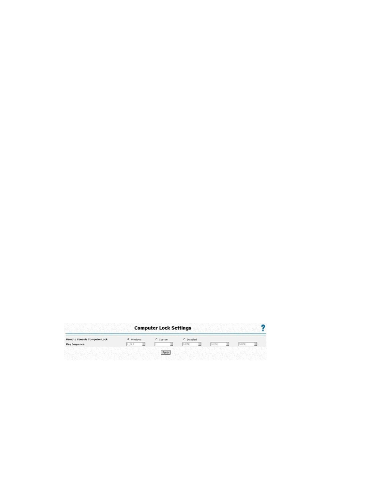
import a server certificate, or directly install a server certificate. For more information, see
“Adding HP SIM trusted servers” (page 56).
The server table displays a list of registered HP SIM servers with the status of each. The actual
number of systems allowed depends on the size of the stored certificate data.
Although a system might be registered, SSO might be refused because of the current trust level
or certificate status. For example, if an HP SIM server name is registered and the trust level is
set to Trust by Certificate, SSO is not allowed from that server. Likewise, if an HP SIM server
certificate is imported, but the certificate has expired, SSO is not allowed from that server.
Additionally, the records are not used when SSO is disabled. iLO 2 does not enforce SSO
server certificate revocation.
— Status – Indicates the status of the record (if any are installed).
— Description – Displays the server name (or certificate subject). A thumbnail of a certificate
indicates that the record contains a stored certificate.
— Actions – Displays the actions you can take on a selected record. The actions displayed
depend on the type and number of records installed:
◦ Remove Name – Removes the server name record.
◦ Remove Certificate – Removes the certificate record.
Remote Console Computer Lock
Remote Console Computer Lock enhances the security of an iLO 2 managed server by automatically
locking an operating system, or logging out a user when a remote console session terminates or
the network link to iLO 2 is lost. Unlike Remote Console or Integrated Remote Console, this feature
is standard and does not require an additional license. As a result, if you open a Remote Console
Session or an Integrated Remote Console window and have this feature configured, it will lock the
operating system when the window is closed even if additional feature licenses are not installed.
You can view and configure the Remote Console Computer Lock settings through the Administration
or Remote Console tabs in the iLO 2 interface. The Remote Console Computer Lock feature is
disabled by default.
To change the Remote Console Computer Lock settings:
1. Log in to iLO 2 using an account that has the Configure iLO 2 Settings privilege.
2. Click Administration>Security>Remote Console. The Computer Lock Settings page appears.
3. Modify the settings as required:
• Windows – Use this option to configure iLO 2 to lock a managed server running a
Windows operating system. The server automatically displays the Computer Locked dialog
box when a remote console session is terminated or the iLO 2 network link is lost.
• Custom – Use this option to configure iLO 2 to use a custom key sequence to lock a
• Disabled – Use this option to disable the Remote Console Computer Lock feature.
58 Configuring iLO 2
managed server or log out a user on that server. You can select up to five keys from the
list. The selected key sequence is automatically sent to the server operating system when
a remote console session is terminated or the iLO 2 network link is lost.
Terminating a remote console session or losing an iLO 2 network link does not lock the
managed server.
Page 59

You can create a Remote Console Computer Lock key sequence using the keys listed in the
following table.
e1F4ESC
f2F5L_ALT
g3F6R_ALT
h4F7L_SHIFT
i5F8R_SHIFT
j6F9L-CTRL
k7F10R_CTRL
l8F11L_GUI
m9F12R_GUI
INS
" " (Space)
n:
o;!DEL
p<"HOME
q=#END
r>$PG_UP
s?%PG_DN
t@&ENTER
u['TAB
v\(BREAK
w])BACKSPACE
x^*NUM PLUS
y_+NUM MINUS
z',SCRL LCK
{a-SYS RQ
}b.F1
|c/F2
~d0F3
4. Click Apply to save changes.
This feature can also be configured using scripting or command lines. For more information, see
the HP Integrated Lights-Out Management Processor Scripting and Command Line Resource Guide
at http://h20000.www2.hp.com/bizsupport/TechSupport/DocumentIndex.jsp?
contentType=SupportManual&lang=en&cc=us&docIndexId=64179&taskId=135&
prodTypeId=18964&prodSeriesId=1146658.
Security 59
Page 60

Network
The Network Settings and DCHP/DNS tabs of the Network section enable you to view and modify
network settings for iLO 2.
Only users with the Configure iLO 2 Settings privilege can change these settings. Users that do
not have the Configure iLO 2 Settings privilege can view the assigned settings.
To change network settings for iLO 2:
1. Log in to iLO 2 using an account that has the Configure iLO 2 Settings privilege. Click
Administration>Network.
2. Select Network Settings or DHCP/DNS.
3. Change the settings as needed.
4. After completing any parameter changes, click Apply to complete the changes.
iLO 2 restarts, and the connection of your browser to iLO 2 terminates. To reestablish a connection,
wait 60 seconds before launching another browser session and logging in.
Network Settings
The Network Settings page displays the NIC IP address, subnet mask, and other TCP/IP-related
information and settings. From the Network Settings screen, you can enable or disable DHCP and
configure a static IP address for servers not using DHCP. All users can view the network settings,
but only users with the Configure iLO 2 Settings privilege can change these settings. To access the
Network Settings page, click Administration>Network>Network. The Network Settings page
appears with the following information and settings:
• NIC enables you to set the iLO 2 NIC to Enabled, Disabled, or to Shared Network Port.
Enabled – Enables the primary iLO 2 network interface.◦
◦ Disabled – Disables the iLO 2 network interface. You must use the iLO 2 RBSU or other
host-based scripting utility to re-enable the network interface.
◦ Shared Network Port – Enables networking using the designated host Ethernet port. The
port appears as two separate Ethernet MACs and IP addresses on the network. For more
information, see “iLO 2 Shared Network Port” (page 61).
• DHCP enables you to select static IP (disabled) or enables the use of a DHCP server to obtain
an IP address for the Integrated Lights-Out 2 subsystem.
You cannot set the iLO 2 IP Address and Subnet Mask if DHCP is enabled. Disabling DHCP
enables you to configure the IP address. The IP Address field also appears on the DHCP/DNS
Settings page for convenience. Changing the value on either page changes the DHCP setting.
• IP Address is the iLO 2 IP address. If DHCP is used, the iLO 2 IP address is automatically
supplied. If not, enter a static IP address. The IP Address field appears on the DHCP/DNS
page for convenience. Entering values in the field on either page changes the IP address of
the iLO 2.
• Subnet Mask is the subnet mask of the iLO 2 IP network. If DHCP is used, the Subnet Mask is
automatically supplied. If not, enter the subnet mask for the network.
• Gateway IP Address displays the IP address of the network gateway. If DHCP is in use, the
Gateway IP Address is automatically supplied. If not, enter the network gateway address.
60 Configuring iLO 2
Page 61

• iLO 2 Subsystem Name is a name used by the iLO 2 subsystem. If DHCP and DNS are
configured correctly, this name can be used to connect to the iLO 2 subsystem instead of the
IP address. For more information, see “iLO 2 subsystem name limitations” (page 61).
• Link controls the speed and duplex of the iLO 2 network transceiver. The current link speed
of the primary dedicated iLO 2 NIC can be highlighted. Link settings include the following:
— Automatic (default) enables iLO 2 to negotiate the highest supported link speed and
duplex when connected to the network.
— 100Mb/FD forces a 100-Mb connection using full duplex.
— 100Mb/HD forces a 100-Mb connection using half duplex.
— 10Mb/FD forces a 10-Mb connection using full duplex.
— 10Mb/HD forces a 10-Mb connection using half duplex.
NOTE: If autosense is disabled, the network switch must match the iLO 2 settings to prevent
iLO 2 access issues.
You are not permitted to modify the NIC speed settings and autosense options on blade
servers. These settings are auto negotiated between iLO 2 and the Onboard Administrator.
iLO 2 subsystem name limitations
The iLO 2 subsystem name represents the DNS name of the iLO 2 subsystem. For example, ilo
instead of ilo.hp.com. This name can only be used, if DHCP and DNS are configured properly
to connect to the iLO 2 subsystem name instead of the IP address.
• Name service limitations – The subsystem name is used as part of the DNS name and WINS
name. However DNS and WINS limitations differ:
— DNS allows alphanumeric and hyphen. WINS allows alphanumeric, hyphen and
underscore.
— WINS subsystem names are truncated at 15 characters, DNS are not.
If you require underscores, they can be entered in RBSU or using the iLO 2 scripting utility.
NOTE: Name service limitations also apply to the domain name.
To avoid name space issues:
◦ Do not use the underscore character.
◦ Limit subsystem names to 15 characters.
◦ Verify you can ping iLO by IP address and by DNS/WINS name.
◦ Verify NSLOOKUP correctly resolves the iLO network address and that there are no
namespace conflicts.
◦ Verify DNS and WINS both correctly resolve the name (if you are using both).
◦ Flush the DNS name if you make any name space changes.
iLO 2 Shared Network Port
The iLO 2 Shared Network Port enables you to choose either the system NIC or dedicated iLO 2
Dedicated Management NIC for server management. When you enable the iLO 2 Shared Network
Port, both regular network traffic, and network traffic intended for iLO 2 pass through the system
NIC.
Network 61
Page 62

iLO 2 provides support for servers that might not have an iLO 2 Dedicated Management NIC. On
servers using the iLO 2 Dedicated Management NIC, the standard hardware configuration provides
iLO 2 network connectivity only through the iLO 2 Shared Network Port connection. iLO 2 detects
the lack of an iLO 2 Dedicated Management NIC and automatically defaults to the Shared Network
Port. On some of these servers, an iLO 2 Dedicated Management NIC might be available as a
hardware option. If an iLO 2 Dedicated Management NIC is available as a hardware option, iLO
2 defaults to the installed iLO 2 Dedicated Management NIC. On servers using the iLO 2 Dedicated
Management NIC, you can enable shared network port operation through the iLO 2 interface.
The iLO 2 Shared Network Port uses the network port labeled NIC 1 on the rear panel of the
server. NIC numbering in the operating system can be different from system numbering. The iLO
2 Shared Network Port does not incur an iLO 2 performance penalty. Peak iLO 2 traffic is less
than 2 MB (on a NIC capable of 1000-Mb speeds), and average iLO 2 traffic is infrequent and
low.
The Shared Network Port is not available on HP ProLiant ML310 G3, ML310 G4, BL20p G4, and
all c-Class blade servers.
iLO 2 Shared Management Port features and restrictions
iLO 2 Shared Network Port and the iLO 2 Dedicated Management NIC port are used for iLO 2
server management. You can only use the iLO 2 Shared Network Port and the iLO 2 Dedicated
Management NIC port for iLO 2 server management. The iLO 2 Shared Network Port and the iLO
2 Dedicated Management NIC port cannot operate simultaneously. If you enable the dedicated
iLO 2 NIC, you will disable the iLO 2 Shared Network Port. If you enable the iLO 2 Shared Network
Port, you will disable the dedicated iLO 2 Dedicated Management NIC.
However, disabling the Shared Network Port does not completely disable the system NIC. Regular
network traffic still passes through the system NIC. When Shared Network Port network traffic is
disabled, any traffic going to or originating from iLO 2 will not pass on to iLO 2 through the Shared
Network Port because the Shared Network Port is no longer shared with iLO 2.
The Shared Network Port must not be considered an availability feature. The Shared Network Port
is intended to allow managed network port consolidation. The use of this feature can create a
single failure point, that is, if the port fails or is unplugged, both the host and iLO 2 become
unavailable to the network.
Enabling the iLO 2 Shared Network Port feature
The iLO 2 Shared Network Port feature is disabled by default. This feature can be enabled through
one of the following:
• The iLO 2 RBSU
• The iLO 2 web interface
• XML scripting
Enabling the iLO 2 Shared Network Port feature through iLO 2 RBSU
1. Connect the server's NIC port 1 to a LAN.
2. When prompted during POST, press the F8 key to enter iLO 2 RBSU.
3. Select Network>NIC>TCP/IP, and press the Enter key.
4. In the Network Configuration menu, toggle the Network Interface Adapter Field to Shared
Network Port by pressing the space bar. The Shared Network Port option is only available
on supported servers.
62 Configuring iLO 2
Page 63

5. Press the F10 key to save the configuration.
6. Select File>Exit, and press the Enter key.
After iLO 2 resets, the Shared Network Port feature is active. Any network traffic going to or
originating from iLO 2 is directed through the system's NIC port 1.
Enabling the iLO 2 Shared Network Port feature through the web interface
1. Connect iLO 2 NIC port 1 to a LAN.
2. Open a browser, and browse to the iLO 2 IP address or DNS name.
3. Select Administration>Network Settings.
4. On the Network Settings page, select Shared Network Port. The Shared Network feature is
available on supported servers only.
5. Click Apply at the bottom of the page.
6. Click Yes in the warning dialog box, and click OK.
After iLO 2 resets, the Shared Network Port feature is active. Any network traffic going to or
originating from iLO 2 is directed through the system's NIC port 1.
Only the Shared Network Port or the iLO 2 Dedicated Management NIC is active for server
management. They cannot be enabled at the same time.
Re-enabling the dedicated iLO 2 management port
The iLO 2 web interface, RBSU, or XML (described in the scripting and command line reference
guide) scripting must be used to re-enable the iLO 2 Dedicated Management NIC. Re-enabling
iLO 2 through RBSU requires that the system be rebooted.
To re-enable the iLO 2 Dedicated Management NIC using RBSU:
1. Connect the iLO 2 dedicated management NIC port to a LAN from which the server is
managed.
2. Reboot the server.
3. When prompted during POST, press the F8 key to enter iLO 2 RBSU.
4. Select Network>NIC>TCP/IP, and press the Enter key.
5. In the Network Configuration menu, toggle the Network Interface Adapter Field to ON by
pressing the space bar.
6. Press the F10 key to save the configuration.
7. Select File>Exit, and press the Enter key.
After iLO 2 resets, the iLO 2 Dedicated Management NIC port is active.
To re-enable the iLO 2 Dedicated Management NIC using iLO 2 interface:
Network 63
Page 64

1. Open a browser and navigate to the iLO 2 IP address or DNS name
2. On the Network Settings page, select Enabled for the iLO 2 NIC.
3. Click Apply. A warning dialog appears.
4. Click Yes, and then OK.
After iLO 2 resets, the iLO 2 Dedicated Management NIC is active. When using IRC through iLO
2 Dedicated Management NIC port and depending on the network traffic, you might not have
sufficient time to press the RBSU keys during POST.
DHCP/DNS Settings
The iLO 2 DHCP/DNS Settings page displays DHCP/DNS configuration information for iLO 2.
All users can view the DHCP/DNS settings, but you must have the Configure iLO 2 Settings privilege
to change them. These settings can also be changed using the iLO 2 RBSU (F8 during POST). To
access DHCP/DNS settings, click Administration>Network>DHCP/DNS. The DHCP/DNS Settings
page appears.
The following options are available:
• DHCP allows you to select static IP (disabled) or enable the use of a DHCP server to obtain
an IP address for the iLO 2 subsystem.
You cannot set the iLO 2 IP address if DHCP is enabled. Disabling DHCP allows you to
configure the IP address. The IP Address field also appears on the Network Settings page for
your convenience. Changing the value on either page changes the DHCP setting.
• IP Address is the iLO 2 IP address. If DHCP is used, the iLO 2 IP address is automatically
supplied. If not, enter a static IP address. The IP Address field appears on the Network Settings
page for your convenience. Changing the value on either page changes the IP address of iLO
2.
64 Configuring iLO 2
Page 65

• Domain Name is the name of the domain where the iLO 2 subsystem resides. This name is
assigned by DHCP (if DHCP is enabled). Enabling DHCP allows you to configure the following
DHCP options:
— Use DHCP Supplied Gateway – Toggles if iLO 2 uses the DHCP server-supplied gateway.
If not, enter an gateway address in the Gateway IP Address box.
— Use DHCP Supplied DNS Servers – Toggles if iLO 2 uses the DHCP server-supplied DNS
server list. If not, enter the DNS server address in the Primary, Secondary, and Tertiary
DNS Server fields.
— Use DHCP Supplied WINS Servers – Toggles if iLO 2 uses the DHCP server-supplied
WINS server list. If not, enter the WINS server address in the Primary and Secondary
WINS Server fields.
— Use DHCP Supplied Static Routes – Toggles if iLO 2 uses the DHCP server-supplied static
route. If not, enter the static route address in Static Route #1, Static Route #2, or Static
Route #3 fields.
— Use DHCP Supplied Domain Name – Toggles if iLO 2 uses the DHCP server-supplied
domain name. If not, enter a domain name in the Domain Name box.
• WINS Server Registration toggles if iLO 2 registers its name with a WINS server.
• DDNS Server Registration toggles if iLO 2 registers its name with a DDNS server.
• Ping Gateway on Startup option causes iLO 2 to send four ICMP echo request packets to the
gateway when iLO 2 initializes. This option ensures that the ARP cache entry for iLO 2 is
up-to-date on the router responsible for routing packets to and from iLO 2.
• DHCP Server is the IP address of the DHCP server. This field cannot be assigned. It is received
from DHCP if DHCP is enabled and represents the last known valid DHCP server address.
• Primary, Secondary, and Tertiary DNS Server are the IP addresses of the DNS servers. If
supplied by the DHCP server, these fields are automatically populated. Otherwise, enter the
IP addresses manually.
• Primary and Secondary WINS Server are the IP addresses of the WINS servers. If supplied
by the DHCP server, these fields are automatically populated. Otherwise, enter the IP addresses
manually.
• Static Route #1, Static Route #2, and Static Route #3 (destination, gateway) are the network
destination gateway addresses. Enter up to three network destination/gateway routing pairs.
SNMP/Insight Manager settings
The Management option of the Administration section displays the SNMP/Insight Manager Settings
page. The SNMP/Insight Manager Settings page enables you to configure SNMP alerts, generate
a test alert, and configure integration with HP SIM.
Enabling SNMP alerts
iLO 2 supports up to three IP addresses to receive SNMP alerts. Typically, the addresses used are
the same as the IP address of the HP SIM server console.
Only users with the Configure iLO 2 Settings privilege can change these settings. Users that do
not have the Configure iLO 2 Settings privilege can only view the assigned settings.
The following alert options are available in the SNMP/Insight Manager Settings screen:
• SNMP Alert Destination(s)
• iLO 2 SNMP Alerts
• Forward Insight Manager Agent SNMP Alerts
SNMP/Insight Manager settings 65
Page 66

• SNMP Pass-thru
• p-Class Alert Forwarding (displayed on p-Class servers only)
For more information see to the HP Integrated Lights-Out Management Processor Scripting and
Command Line Resource Guide at http://h20000.www2.hp.com/bizsupport/TechSupport/
DocumentIndex.jsp?contentType=SupportManual&lang=en&cc=us&docIndexId=64179&
taskId=135&prodTypeId=18964&prodSeriesId=1146658.
To configure alerts:
1. Log in to iLO 2 using an account that has the Configure iLO 2 Settings privilege.
2. Select Management in the Administration tab. The SNMP/Insight Manager Settings screen
appears.
3. In the SNMP Alert Destination(s) fields, enter up to three IP addresses that you want to receive
the SNMP alerts and select the alert options you want iLO 2 to support.
4. Click Apply Settings.
Test alerts include an Insight Manager SNMP trap and are used to verify the network connectivity
of iLO 2 in HP SIM. Only users with the Configure iLO 2 Settings privilege can send test alerts.
Be sure you have saved any changes to the SNMP Alert Destination(s) fields before sending a test
alert.
To send a test alert:
1. Select Management in the Administration tab. The SNMP/Insight Manager Settings screen
appears.
2. Click Send Test Alert in the Configure and Test SNMP Alerts section to generate a test alert
and send it to the TCP/IP addresses saved in the SNMP Alert Destinations fields.
3. After generating the alert, a confirmation screen appears.
4. Check the HP SIM console for receipt of the trap.
SNMP generated trap definitions
You can generate the following SNMP traps on BL c-Class servers and iLO 2:
• ALERT_TEST – Verifies that the SNMP configuration, client SNMP console, and network are
operating correctly. You can use the iLO 2 interface to generate this alert to verify receipt of
the alert at the SNMP console. You can also generate this alert using the iLO 2 Option ROM
to verify SNMP configuration settings.
• ALERT_SERVER_POWER – Occurs when the iLO 2 management processor detects an
unexpected transition of the host system power, either from ON to OFF, or OFF to ON.
66 Configuring iLO 2
Page 67

Transitions of the host system power are unexpected when the change takes place because
of events unknown to the management processor. This alert is not generated when the system
is powered up or down using the iLO 2 interface, CLI, RIBCL or other management feature. If
the server is powered down because of the operating system, physical power button presses,
or other methods, the alert is generated and sent.
• ALERT_SERVER_RESET – Occurs when the iLO 2 management processor is used to perform
a cold boot or warm boot of the host system. This alert is also sent when the iLO 2 management
processor detects the host system is in reset because of events unknown to the management
processor. Certain operating system behavior or actions can cause this type of event to be
detected, and the alert transmitted.
• ALERT_ILLEGAL_LOGIN – An SNMP alert transmitted when a connection is attempted using
an invalid username and password. This alert is transmitted regardless of connection type;
web interface, serial port, Telnet, SSH, or RIBCL.
• ALERT_LOGS_FULL – An SNMP alert transmitted when the iLO 2 Event Log is full and an
attempt to log a new event occurs.
• ALERT_SELFTEST_FAILURE – An SNMP alert transmitted when iLO 2 detects an error in
any one of the monitored internal components. If an error is detected an SNMP alert is
transmitted.
• ALERT_SECURITY_ENABLED – Alert is transmitted when the iLO 2 management processor
detects a change in the Security Override Switch to enabled.
• ALERT_SECURITY_DISABLED – An SNMP alert transmitted when the iLO 2 management
processor detects a change in the Security Override Switch to disabled.
• ALERT_HOST_GENERATED – An SNMP alert generated when the iLO 2 management processor
was asked to transmit a Host (SNMP passthrough) alert and the management processor was
unable to transmit the original SNMP alert. iLO 2 attempts to transmit this generic alert in
order to notify the SNMP management console that an alert intended to be transmitted from
the host system was not transmitted.
Configuring Insight Manager integration
The Insight Manager Web Agent URL (DNS name or IP address) sets the browser destination of
the Insight Agent link on iLO 2 pages. Typically, this link is the IP address or DNS name of the
management agent running on the host server operating system.
Enter the IP address of the host server. The protocol (https://) and port number (:2381) are
automatically added to the IP address or DNS name to allow access to the Insight Management
Web Agents from iLO 2.
If the Insight Manager Web Agent URL is set through another method (for example, CPQLOCFG),
click the refresh button of your browser to display the updated URL.
The Level of Data Returned setting controls the content of an anonymous discovery message received
by iLO 2. The information returned is used for Insight Manager HTTP identification requests. The
following options are available:
• Enabled (default) – Enables Insight Manager to associate the management processor with the
host server and provides sufficient data to allow integration with HP SIM.
• Disabled – Prevents iLO 2 from responding to the HP SIM requests.
• View XML Reply – Enables you to examine the data returned at the settings.
View the response that is returned to Insight Manager when it requests Management Processor
identification using this link.
To see the results of changes made, click Apply Settings to save the changes. To return the page
to its previous state and clear the fields, click Reset Settings. The Reset Settings button does not
save any changes.
SNMP/Insight Manager settings 67
Page 68

For more information on Insight Agents, click System Status>Insight Agent.
Static IP bay configuration
Static IP bay configuration is implemented using the Static IP Bay Settings option on the BL p-Class
tab. This option eases the initial deployment of an entire enclosure or the subsequent deployment
of blades within an existing enclosure. While the preferred method for assigning IP addresses to
the iLO 2 in each blade server is through DHCP and DNS, these protocols are not always available
on nonproduction networks.
For example, after configuring Static IP Bay configuration for the blade in bay 1, subsequent blade
additions to the enclosure assume subsequent addresses without DHCP. The network addresses
are assigned by blade position bay 1: 192.168.1.1, bay 2: 192.168.1.2, and so on.
Deploying subsequent blades does not demand extra configuration, and the network address
corresponds to the bay number.
Static IP bay configuration automates the first step of BL p-Class blade deployment by enabling the
iLO 2 management processor in each blade slot to obtain a predefined IP address without relying
on DHCP. iLO 2 is immediately accessible for server deployment using Virtual Media and other
remote administration functions.
Static IP bay configuration uses the Static IP Bay Configuration addressing method, which enables
you to assign IP addresses to each iLO 2 based on slot location in the respective server enclosure.
By providing a set of IP addresses in the enclosure, you gain the advantages of a static IP bay
configuration without requiring each individual iLO 2 to be configured locally.
Using iLO 2 static IP bay configuration:
• Helps avoid the costs of a DHCP infrastructure to support the blade environment
• Provides easier setup with automatic iLO 2 address generation for all or a few selected bays
Static IP Bay Configuration is not supported in G1 BL-series blade enclosures. To view the enclosure
generation, click BL p-Class>Rack View>Details for a specific enclosure. Static IP Bay configuration
is not supported on an enclosure when Enclosure Type details displays the message BL
Enclosure G1
When a blade is redeployed, Static IP Bay Configuration might not complete as expected. To
correct this, verify that the blade is using the current iLO 2 firmware, and then reset the iLO 2
configuration to factory default settings using iLO 2 RBSU.
Configuring a ProLiant BL p-Class blade enclosure
To configure a BL p-Class blade enclosure using static IP bay addressing:
1. Install a server blade in bay 1 of the BL p-Class enclosure. The server blade does not need to
be configured or have an operating system installed. The server blade must be configured
before installing any additional blades in the enclosure.
2. Connect a client device to the front-panel iLO 2 port of the blade using the local I/O cable.
The local I/O cable connects to the I/O port on the front of the server blade. This connection
enables the static IP 192.168.1.1 for the iLO 2 Web interface.
3. Configure the enclosure setting. Using the iLO 2 Web interface, select the BL p-Class tab to
access the Enclosure Static IP Settings. The BL p-Class tab provides a user interface for
configuring the enclosure-level static IP addresses.
4. Select a reasonable starting IP address, with the last digit(s) of the address corresponding to
the bay number of each blade (example: 192.168.100.1 through 192.168.100.16), to
build an easy-to-remember numbering system.
5. Reset bay #1, if necessary. The blade in bay #1 must only be reset if you intend the blade to
use a Static IP bay Configuration address by marking the feature enable mask for bay #1.
Before resetting the blade, browse to the Network Settings page, select Enable Static IP Settings
and click Apply to force the blade to reboot and use the newly assigned enclosure static IP.
68 Configuring iLO 2
Page 69

If multiple enclosures are deployed at the same time, the process can be repeated easily by moving
a single blade to bay #1 of each enclosure to perform the configuration.
Configuring static IP bay settings
Static IP bay settings are available on the BL p-Class tab and enable you to configure and deploy
the blade server. When configuring these settings, you must use the blade in bay 1.
The Enable Static IP Bay Configuration Settings checkbox, available on the Network Settings tab
(not shown), allows you to enable or disable Static IP Bay Configuration. The new Enable Static
IP Bay Configuration Settings option is only available on blade servers. When Static IP Bay
Configuration is enabled, all fields except iLO 2 Subsystem Name are disabled. Only Static IP
Bay Configuration or DHCP can be enabled at one time. Disabling both Static IP Bay Configuration
and DHCP signals iLO 2 to use a user-defined IP address. The Enable Static IP Bay Configuration
Settings option remains disabled if the infrastructure does not support Static IP Bay Configuration.
ProLiant BL p-Class standard configuration parameters
Beginning IP Address (Bay 1) – Assigns the starting IP address. All IP addresses must be valid
addresses.
Ending IP Address (Bay 16) – Assigns the ending IP address. All IP addresses must be valid
addresses.
Subnet Mask – Assigns the subnet mask for the default gateway. This field might be filled in if either
Static IP Bay Configuration or DHCP is enabled. The entire IP address range must conform to the
subnet mask.
Gateway IP Address – Assigns the IP address of the network router that connects the Remote Insight
subnet to another subnet where the management PC resides. This field might be filled in if either
Static IP Bay Configuration or DHCP is enabled.
ProLiant BL p-Class advanced configuration parameters
Domain Name – Enables you to assign the name of the domain in which the iLO 2 will participate.
Primary DNS Server – Assigns a unique DNS server IP address on your network.
Secondary DNS Server – Assigns a unique DNS server IP address on your network.
Tertiary DNS Server – Assigns a unique DNS server IP address on your network.
Static IP bay configuration 69
Page 70

Primary WINS Server – Assigns a unique WINS server IP address on your network.
Secondary WINS Server – Assigns a unique WINS server IP address on your network.
Static Route #1, #2, and #3 (destination gateway) – Assigns the appropriate static route destination
and gateway IP address on your network (the default IP values are 0.0.0.0 and 0.0.0.0, where
the first IP address corresponds to the destination IP, and the second IP address corresponds to the
gateway IP).
Enabling iLO 2 IP address assignment
The bay #1 through bay #16 checkboxes enable you to select which BL p-Class blade servers will
be configured. You can Enable All, Clear All, or Apply your selection.
HP BladeSystem setup
The HP BladeSystem setup wizard provides step-by-step instructions to simplify single blade setup
without requiring DHCP or PXE. The HP BladeSystem Setup page launches after you authenticate
to iLO 2 from the front port.
The server blade must be properly cabled for iLO 2 connectivity. Connect to the server blade
through the server blade I/O port, while the blade is in the rack. This method requires you to
connect the local I/O cable to the I/O port and a client PC. Using the static IP address listed on
the I/O cable label and the initial access information on the front of the server blade, you can
access the server blade through iLO 2 through its standard Web browser interface.
Although any blade can be used for access, if you use a static IP bay configuration to configure
iLO 2 network settings, then the first blade in the enclosure must be used for access.
The first page of the wizard automatically launches if:
• This blade is new from the factory, and you have logged into iLO 2 from the front port.
• You did not fully complete the wizard by selecting Finish on the final page, and you did not
select Do not show setup wizard again and clicked Cancel on the beginning page.
• You have set iLO 2 back to factory default settings.
Click Cancel to close the automated setup wizard. Click Next to set up your blade server. The setup
wizard will guide you through:
70 Configuring iLO 2
Page 71

1. iLO 2 configuration
2. Server RAID verification
3. Virtual media connection
4. Software installation
The iLO 2 firmware configuration screen
This screen enables you to change the following settings:
• Administrator password. HP recommends changing the default password.
• Network configuration settings. The following are the default settings:
Enable DHCP – Yes◦
◦ Enable Static IP Bay Configuration – No
• If connected to the blade in enclosure slot 1, you can enable Static IP Bay configuration to
preconfigure the static address for other iLO 2 processors in the enclosure.
In the default configuration, the iLO 2 being updated gets its IP address through DHCP. Other iLO
2 processors in the enclosure must be configured separately. If these settings are not changed,
clicking Next displays the next page in the setup wizard. If either of these settings are changed,
iLO 2 reboots to invoke the updated settings.
The following configuration combinations are also available (the default setting is in parentheses):
• Enable DHCP (Yes) and Enable Static IP Bay Configuration (Yes)
This configuration causes the iLO 2 being configured to get its IP address through DHCP.
Clicking Next displays the Static IP Bay Configuration page, enabling you to specify the IP
addresses for other iLO 2s in the enclosure. After you click Next, you are prompted to verify
that you want to use DHCP for this iLO 2 IP address.
• Enable DHCP (No) and Enable Static IP Bay Configuration (Yes)
This configuration causes the iLO 2 being configured to set its IP address according to the
settings specified through the Static IP Bay Configuration. Clicking Next displays the Static IP
Bay Configuration page.
• Enable DHCP (No) and Enable Static IP Bay Configuration (No)
This configuration causes the iLO 2 being configured to set its IP address according to the
settings specified through the Network Settings page. Clicking Next displays the Network
Settings page.
To save any network changes, you must have the Configure iLO 2 privilege.
Click Next to save changes and continue.
Verify Server RAID Configuration screen
This step of the installation wizard enables you to verify and accept server RAID configuration
settings. Verify the detected RAID level for the hard drives on the blade server displayed on the
web page and do one of the following:
• Click Next to keep current RAID settings.
• Click Default Settings to automatically configure the RAID level based on the number of installed
drives. You are prompted to verify that you want to reset the RAID level because this could
result in loss of data. Resetting the RAID level requires a server power-on or reboot. iLO 2
displays a page indicating that this action is occurring. The page is refreshed automatically
every 10 seconds. After the server reboots, the next page in the installation wizard displays
again. If an error occurs during the RAID reset process, the RAID Configuration page will
redisplay with an indication of the error. An error is most likely to occur if the server is in
Static IP bay configuration 71
Page 72

POST. If this is the case, exit any RBSU program you are running, allow POST to complete,
and try the operation again.
You can change the RAID level manually through RBSU. If the operating system is already installed,
changing the RAID level results in a loss of data.
Connect Virtual Media screen
This step of the installation wizard enables you to verify and accept the drive you will use during
the installation of the operating system. Under Settings, select the local drive and media type you
intend to use during operating system installation. Click Launch Virtual Media to launch the Virtual
Media applet.
• Ensure the operating system media is connected. In the Virtual Media applet, a green icon
appears next to the media currently selected.
• Verify that the operating system media is in the appropriate local drive.
• Accept security certificates as they appear.
After making your selection, click Next to save your settings and continue. The virtual media applet
appears. After the applet is available, you can change the selected drive, or select other options
not available on the installation wizard page.
Install Software screen
This step of the installation wizard enables you to launch the Remote Console and install the
operating system. To start the operating system installation process:
• Click Launch Software Installation to launch the Remote Console. iLO 2 automatically initiates
a server power-on or reboot to start the operating system installation through the previously
selected virtual media.
• Accept security certificates as they appear.
Click Finish to complete the setup process.
iLO 2 diagnostic port configuration parameters
The iLO 2 Diagnostic Port on the front of ProLiant BL p-Class servers enables you to access and
troubleshoot server issues by using a diagnostic cable. The iLO 2 Diagnostic Port uses a static IP
address. It does not use DHCP to obtain an IP address, register with WINS or dynamic DNS, or
use a gateway. The diagnostic port cable must not be left plugged in without an active network
connection because it will cause degraded network performance on the standard iLO 2 network
port.
In Network Settings, you can configure specific diagnostic port information. For more information
on using the diagnostic port and the diagnostic cable, see to the setup and installation guide for
the blade server.
The following are the fields that can be configured for the Diagnostic Port:
• Enable NIC
If Enable NIC is set to Yes, the diagnostic port is enabled.
• Transceiver Speed Autoselect
• Speed
• Duplex
72 Configuring iLO 2
Page 73

• IP Address
Use this parameter to assign a static IP address to iLO 2 on your network. By default, the IP
address is assigned by DHCP. By default, the IP address is 192.168.1.1 for all iLO 2
Diagnostic Ports.
• Subnet Mask
— Use the subnet mask parameter to assign the subnet mask for the iLO 2 Diagnostic Port.
By default, the subnet mask is 255.255.255.0 for all iLO 2 Diagnostic Ports.
— The use of the Diagnostic Port is automatically sensed when an active network cable is
plugged in to it. When switching between the diagnostic and back ports, you must allow
90 seconds for the network switchover to complete before attempting connection through
the web browser.
NOTE: The diagnostic port does not switch over if an active Remote Console session
or a firmware update is in progress.
Static IP bay configuration 73
Page 74
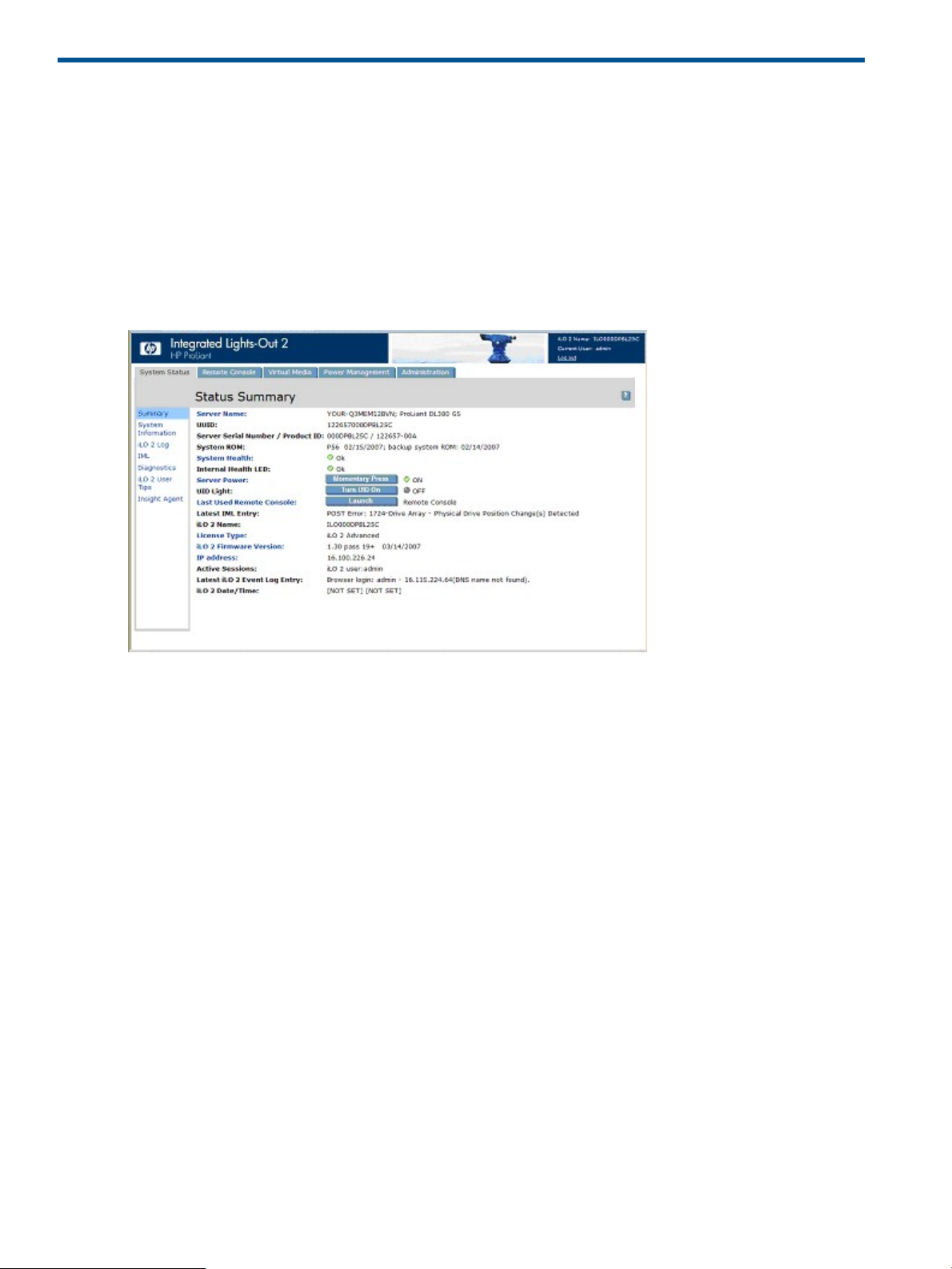
4 Using iLO 2
System status and status summary information
When you first access iLO 2, the interface displays the Status Summary page with system status
and status summary information, and provides access to health information, system logs, and
Insight Agent information. The options available in the System Status section are: Summary, System
Information, iLO 2 Log, IML, Diagnostics, iLO 2 User Tips, and Insight Agents.
The Status Summary page displays high-level details about the system and iLO 2 subsystem, as
well as links to commonly used features. To access the Status Summary page from other areas of
the iLO 2 interface, click System Status>Summary.
Status information includes:
• Server Name – Displays the name of the server and is a link to Administration>Options>Access.
• UUID – Displays the ID of the server.
• Server Serial Number/Product ID – Displays the serial number of the server, which is assigned
when the system is manufactured. You can change this setting using the system RBSU during
POST. Product ID distinguishes between different systems with similar serial numbers. Although
the Product ID is assigned when the system is manufactured, you can change this setting using
the system RBSU during POST.
• System ROM – Displays the family and version of the active system ROM. If the system supports
a backup system ROM, the backup date is also shown.
• System Health – Summarizes the condition of the monitored subsystems including overall status
and redundancy (ability to handle a failure) and is a link to System>Status>System Information
Summary.
• Internal Health LED – Represents the server internal health indicator (if supported). It summarizes
issues with fans, temperature sensors, VRMs, and other monitored subsystems in the server.
For more information, see “System Information Summary” (page 75).
• TPM Status – Displays TPM status configuration. If the host system or System ROM does not
support TPM. TPM Status does not appear in Status Summary page. For more information,
see “Trusted Platform Module support” (page 43).
• Server Power – Displays the current power state of the server (ON/STANDBY) when the page
was loaded and is a link to Server>Power Management. Users with virtual power and reset
privilege can also use the Momentary Press button.
74 Using iLO 2
Page 75

• UID Light – Displays the state of the UID light when the page was loaded. You can control the
UID state using the Turn UID On button in addition to the physical UID buttons on the server
chassis.
The UID helps you identify and locate a system, especially in high-density rack environments.
Additionally, the UID indicates that a critical operation is underway on the host, such as
Remote Console access or firmware update.
CAUTION: Never remove power from a server with a flashing UID.
The current state of the UID (on or off) is the last state chosen using one of these methods. If
a new state is chosen while the UID is blinking, the new state becomes the current state and
takes effect when the UID stops blinking. While the UID is blinking, the current state of the
UID is shown along with the tag flashing. When the UID stops blinking, the tag is removed.
The UID is not supported on the HP ProLiant ML310 G3.
• Last Used Remote Console – Displays the previously launched remote console and its
availability, which enables you to quickly launch your preferred Remote Console. You can
use the Remote Console if it is available and you have the appropriate user privilege. You
can pick a different console by following the Last Used Remote Console link.
• Latest IML Entry – Displays the most recent entry in the IML.
• iLO 2 Name – Displays the name assigned to the iLO 2 subsystem. By default, this is the word
iLO added to the system serial number. This value is used for the network name and must be
unique.
• License Type – Displays whether the system has a feature license installed and is a link to
Administration>Licensing. Some features of iLO 2 cannot be accessed unless licensed.
• iLO 2 Firmware Version – Displays information about the version of iLO 2 firmware currently
installed and is a link to the iLO 2 Release Notes page which highlights new capabilities in
the current firmware release and in selected previous releases
• IP Address – Displays the network IP address of the iLO 2 subsystem and is a link to
Administration>Network Settings.
• Active Sessions – Displays all users currently logged in to iLO 2.
• Latest iLO 2 Event Log Entry – Displays the most recent entry in the iLO 2 Event Log.
• iLO 2 Date – Displays the date (MM/DD/YYYY) as indicated by the iLO 2 subsystem internal
calendar. The iLO 2 internal calendar is synchronized with the host system at POST and when
the Insight Agents run.
• iLO 2Date/Time – Displays the iLO 2 subsystem internal clock. The iLO 2 internal clock is
synchronized with the host system at POST and when the Insight Agents run.
System Information Summary
System Information displays the health of the monitored system. Many of the features necessary to
operate and manage the components of the HP ProLiant server have migrated from the health
driver to the iLO 2 microprocessor. These features are available without installing and loading the
health driver for the installed operating system. The iLO 2 microprocessor monitors these devices
when the server is powered on during server boot, operating system initialization, and operation.
Monitoring continues through an unexpected operating system failure. To access System Information,
click System Status>System Information. The System Health Summary tab appears. System
Information also displays the following embedded health tabs: “Fans” (page 76), “Temperatures”
(page 76), “Power” (page 77), “Processors” (page 77), “Memory” (page 77), and “NIC” (page
77).
The Summary tab displays the state of monitored host-platform subsystems status at a glance,
summarizing the condition of the monitored subsystems, including overall status and redundancy
System status and status summary information 75
Page 76

(ability to handle a failure). The subsystems can include fans, temperature sensors, power supplies,
and voltage regulator modules.
• Fans – Displays the state of the replaceable fans in the server chassis. This data includes the
area that is cooled by each fan and current fan speeds.
• Temperatures – Displays the temperature conditions monitored at sensors in various locations
in the server chassis, and the processor temperature. The temperature is monitored to maintain
the location temperature below the caution threshold. If the temperature exceeds the caution
threshold, the fan speed is increased to maximum.
• VRMs – Displays VRM status. A VRM is required for each processor in the system. The VRM
adjusts the power to meet the power requirements of the processor supported. A failed VRM
prevents the processor from being supported and must be replaced.
• Power Supplies – Displays the presence and condition of installed power supplies.
OK – Indicates that the power supply is installed and operational.—
— Unpowered – Indicates that the power supply is installed, but not operational. Verify that
the power cord is connected.
— Not present – Indicates that the power supply is not installed. Power is not redundant in
this condition.
— Failed – Indicates that the power supply must be replaced.
To access the Summary tab from other areas of the iLO 2 interface, click System Status>System
Information>Summary.
Fans
iLO 2, in conjunction with additional hardware, controls the operation and speed of the fans. Fans
provide essential cooling of components to ensure reliability and correct operation. Fan location,
placement, design and speed control take into account various temperatures monitored throughout
the system to provide appropriate cooling with minimal noise levels.
Fan operation policies might differ from server to server based on fan configuration and cooling
demands. Fan control takes into account the internal temperature of the system, increasing the fan
speed to provide more cooling, and decreasing the fan speed if cooling is sufficient. In the unlikely
event of a fan failure, some fan operation policies might increase the speed of the other fans,
record the event in the IML, and turn LED indicators on.
Monitoring the fan sub-system includes the sufficient, redundant, and non-redundant configurations
of the fans. Fan failure is a rare occurrence, but to ensure reliability and uptime, ProLiant servers
have redundant fan configurations. In ProLiant servers that support redundant configurations, fan
or fans might fail and still provide sufficient cooling to continue operation. iLO 2 increases fan
control to continue safe operation of the server in the event of fan failure, maintenance operations,
or any event that alters cooling of the server.
In non-redundant configurations, or redundant configurations where multiple fan failures occur,
the system might become incapable of providing the necessary cooling to protect the system from
damage and to ensure data integrity. In this condition, in addition to the cooling policies, the
system might start a graceful shutdown of the operating system and server.
The Fan tab displays the state of the replaceable fans within the server chassis. This data includes
the area cooled by each fan and the current fan speed.
Temperatures
The Temperatures tab displays the location, status, temperature, and threshold settings of temperature
sensors in the server chassis. The temperature is monitored to maintain the location temperature
76 Using iLO 2
Page 77

Power
below the caution threshold. If one or more sensors exceed this threshold, iLO 2 implements the
recovery policy to prevent damage to server components.
• If the temperature exceeds the caution threshold, the fan speed is increased to maximum.
• If the temperature exceeds the critical temperature, a graceful server shutdown is attempted.
• If the temperature exceeds the fatal threshold, the server is immediately turned off to prevent
permanent damage.
Monitoring policies differ depending on server requirements. Policies usually include increasing
fan speed to maximum cooling, logging the temperature event in the IML log, providing visual
indication of the event using LED indicators, and starting a graceful shutdown of the operating
system to avoid data corruption.
After correcting the excessive temperature conditions additional polices are implemented including
returning the fan speed to normal, recording the event in the IML, turning off the LED indicators,
and if appropriate, canceling shutdowns in progress.
The VRMs/Power Supplies tab displays the state of each VRM or power supply. VRMs are required
for each processor in the system. VRMs adjust the power to meet the needs of the processor
supported. A VRM can be replaced if it fails. A failed VRM prevents the processor from being
supported.
iLO 2 also monitors power supplies in the system to ensure the longest available uptime of the
server and operating system. Power supplies can be affected by the brownouts and other electrical
conditions, or AC cords can be accidentally unplugged. These conditions result in a loss of
redundancy if redundant power supplies are configured, or result in loss of operation if redundant
power supplies are not in use. Additionally, if a power supply failure is detected (hardware failure)
or the AC power cord is disconnected, then these events are recorded in the IML and the LED
indicators light.
iLO 2 monitors power supplies to ensure that they are correctly installed. This information appears
on the System Information page. Reviewing the System Information page and IML will assist you
in deciding when to repair or replace a power supply, preventing a disruption in service.
Processors
The Processors tab displays the available processor slots, the type of processor installed in the slot,
and a brief status summary of the processor subsystem. If available, installed processor speed in
MHz and cache capabilities are displayed.
Memory
The Memory tab displays the available memory slots and the type of memory, if any, installed in
the slot.
NIC
The NIC tab displays the MAC addresses of the integrated NICs. This page does not display add-in
network adapters.
iLO 2 Log
The iLO 2 Log page displays the iLO 2 Event Log, which is a record of significant events detected
by iLO 2. Logged events include major server events such as a server power outage or a server
reset and iLO 2 events such as unauthorized login attempts. Other logged events include successful
or unsuccessful browser and Remote Console logins, virtual power and power cycle events, clear
event log actions, and some configuration changes, such as creating or deleting a user.
iLO 2 provides secure password encryption, tracking all login attempts and maintaining a record
of all login failures. Authentication Failure Logging allows you to configure logging criteria for
System status and status summary information 77
Page 78

IML
failed authentications. You can configure tracking failed login attempts for every attempt or every
second, third, or fifth attempt, and captures the client name for each logged entry to improve
auditing capabilities in DHCP environments, as well as recording account name, computer name,
and IP address. When login attempts fail, iLO 2 also generates alerts and sends them to a remote
management console.
Events logged by higher versions of iLO 2 firmware might not be supported by earlier versions. If
an event is logged by an unsupported firmware, the event is listed as UNKNOWN EVENT TYPE.
You can clear the event log to eliminate these entries, or update the firmware to the latest supported
version.
To access the iLO 2 Log, click System Status>iLO 2 Log.
To clear the event log:
1. Click Clear Event Log to clear the event log of all previously logged information.
2. Click OK to confirm that you want to clear the event log. A line indicating that the log has
been cleared is logged.
The IML page displays the Integrated Management Log, which is a record of historical events that
have occurred on the server as reported by various software components. Events are generated
by the system ROM and by services like the System Management (health) driver. The IML enables
you to view logged remote server events. Logged events include all server-specific events recorded
by the system health driver, including operating system information and ROM-based POST codes.
For more information, see to the server guide.
Entries in the IML can assist during issue diagnosis or help identify possible issues before they
occur. Preventative action might be recommended to avoid possible disruption of service. iLO 2
manages the IML, which can be accessed using a supported browser, even when the server is off.
The ability to view the event log even when the server is off can be helpful when troubleshooting
remote host server issues.
You can sort the log by clicking the header of any column of data. After the sort completes, clicking
the same column header again sorts the log in reverse of its current order. Very large logs will take
several minutes to sort and display. You can clear the events in this log on the server's Insight
Manager Web Agents home page.
The iLO 2 processor records the following information to the IML based upon the occurrences in
the system.
• Fan inserted
• Fan removed
• Fan failure
• Fan degraded
• Fan repaired
• Fan redundancy lost
• Fans redundant
• Power supply inserted
• Power supply removed
• Power supply failure
• Power supplies redundancy lost
• Power supplies redundant
• Temperature over threshold
78 Using iLO 2
Page 79

• Temperature normal
• Automatic shutdown started
• Automatic shutdown cancelled
Diagnostics
The Diagnostics option on the System Status tab displays the Server and iLO 2 Diagnostics screen.
The Server and iLO 2 Diagnostic screen displays iLO 2 self-test results, and provides options to
generate an NMI to the system and to reset iLO 2.
NOTE: When connected through the Diagnostics Port, the directory server is not available. You
can log in using a local account only.
The Diagnostics page contains the following sections:
• Non-Maskable Interrupt (NMI) button
The Non-Maskable Interrupt (NMI) button section contains the Generate NMI to System button
which enables you to halt the operating system for debugging. This functionality is an advanced
function and must only be used for kernel-level debugging. The possible uses of the Generate
NMI to System feature include the following:
— Use the Demonstrate ASR feature only if the System Management (health) driver is loaded
and ASR is enabled. The host automatically reboots after an NMI has occurred.
— Use the Debug feature if a software application hangs the system. The Generate NMI to
System button can be used to engage the operating system debugger.
— Initiate the dump of an unresponsive host if you want to capture the server context.
The Virtual Power and Reset privilege is required to generate an NMI. An unexpected NMI
typically signals a fatal condition on the host platform. A blue-screen, panic, ABEND, or other
fatal exception occurs when an unexpected NMI is received by the host operating system,
even when the operating system is unresponsive or locked-up. Generating an unexpected
NMI can be used to diagnose a catatonic or deadlocked operating system. Generating an
NMI crashes the operating system, resulting in lost service and data.
Generating an NMI must only be used in extreme diagnostic cases in which the operating
system is not functioning properly and an experienced support organization has recommended
that you proceed with an NMI. Generating an NMI as a diagnostic and debugging tool is
primarily used when the operating system is no longer available. Generating an NMI must
not be used during normal operation of the server. The Generate NMI to System button does
not gracefully shut down the operating system.
• iLO 2 Self-Test Results
The iLO 2 Self-Test Results sections displays the results of iLO 2 internal diagnostics. iLO 2
performs a series of initialization and diagnostic procedures on the subsystems of the iLO 2
system. The results display on the Server and iLO 2 Diagnostics screen. All tested subsystems
display Passed under normal circumstances. Each test displays one of three results: Passed,
Fault, or N/A.
The status of these self-tests is indicated by the test results and is intended to identify issue
areas. If a Fault test condition is indicated, follow information noted on the screen. The specific
tests that are run is system-dependant. Not all tests are run on all systems. See the iLO 2
Diagnostics page to verify which tests are automatically performed on your system.
• Reset Integrated Lights-Out 2
The Reset Integrated Lights-Out 2 section contains the Reset button which enables you to reboot
the iLO 2 processor. Using Reset does not make any configuration changes. Reset disconnects
any active connections to iLO 2 and completes any firmware updates in progress. You must
System status and status summary information 79
Page 80

have the Configure iLO 2 privilege (configure local device settings) to reset iLO 2 using this
option.
Insight Agents
The HP Insight Management Agents support a browser interface for access to runtime management
data through the HP System Management Homepage. The HP System Management Homepage is
a secure web-based interface that consolidates and simplifies the management of individual servers
and operating systems. By aggregating data from HP Insight Management Agents and other
management tools, the System Management Homepage provides an intuitive interface to review
in-depth hardware configuration and status data, performance metrics, system thresholds and
software version control information.
The agents can automatically provide the link to iLO 2, or you can manually enter the link using
Administration/Management.
For more information, see “HP Systems Insight Manager integration” (page 178), and the HP web
site at http://www.hp.com/servers/manage.
iLO 2 Remote Console
iLO 2 Remote Console redirects the host server console to the network client browser, providing
full text (standard), graphical mode video, keyboard, and mouse access to the remote host server
(if licensed). iLO 2 uses virtual KVM technology to improve remote console performance comparable
with other KVM solutions.
With remote console access, you can observe POST boot messages as the remote host server
restarts and initiate ROM-based setup routines to configure the hardware of the remote host server.
When installing operating systems remotely, the graphical remote consoles (if licensed) enable
you to view and control the host server screen throughout the installation process.
Remote console access provides you complete control over a remote host server as if you were in
front of the system, including access to the remote file system and network drives. Remote Console
enables you to change hardware and software settings of the remote host server, install applications
and drivers, change remote server screen resolution, and gracefully shut down the remote system.
Up to 10 users are allowed to simultaneously log in to iLO 2. However, only four users can access
a shared Integrated Remote Console. If you attempt to open the Remote Console while it is already
in use, a warning message appears, indicating that it is in use by another user. To view the remote
console session already in progress, see “Multi-user access to the Integrated Remote Console”
(page 89). To take control of the session, use the Remote Console Acquire feature, see “Acquiring
the Remote Console” (page 92).
The Remote Console Information page provides access links to the different remote console access
options. After deciding which console option you want to use, click the appropriate link. iLO 2
provides the following remote console access options:
• “Integrated Remote Console option” (page 85) – Provides access to the system KVM, allowing
control of Virtual Power and Virtual Media from a single console using Microsoft Internet
Explorer.
• “IRC Fullscreen” (page 85) – Resizes the Integrated Remote Console to the same display
resolution as the remote host.
The Integrated Remote Console and Integrated Remote Console Fullscreen uses ActiveX and
requires Microsoft Internet Explorer.
• “Remote Console” (page 93) – Provides access to the system KVM through a Java applet-based
console. Remote Console is the familiar Remote Console support carried forward from the
original iLO product. Remote Console support requires that Java be installed on the client
80 Using iLO 2
Page 81

system. Remote Console operates with all operating systems and browsers supported by iLO
2.
• “Remote Serial Console” (page 100) – Provides access to a VT320 serial console through a
Java applet-based console connected to the iLO 2 Virtual Serial Port. The Remote Serial Console
is available without an additional license and is suitable for host operating systems that do
not require access to the graphical console.
Standard iLO 2 provides server console access from server power-on through POST. Integrated
Remote Console, Integrated Remote Console Fullscreen, and Remote Console are graphical remote
consoles that turn a supported browser into a virtual desktop, allowing you full control over the
display, keyboard, and mouse of the host server. The operating-system-independent console supports
graphic modes that display remote host server activities, including shutdown and startup operations
(if licensed).
Remote console access to the host server after server POST is a licensed feature available with the
purchase of optional licenses. For more information, see “Licensing” (page 26). To access iLO 2
Remote Console, click Remote Console. The Remote Console Information page appears.
Remote Console overview and licensing options
Remote Console and Integrated Remote Console connections are graphical and must be rendered
using a client program that can process iLO 2 graphics commands. Two clients are provided to
render the iLO 2 graphics:
• Java-based Remote Console
• Windows Active X-based Integrated Remote Console
For those clients that do not understand iLO 2 graphics, SSH and Telnet, you must use the iLO 2
Remote Serial Console or purchase an iLO Advanced license to use the text-based console after
POST.
ESX consoles, in particular ESX console 1, do not fully support iLO 2 Remote Console and Integrated
Remote Console. ESX does not support Remote Serial Console.
iLO 2 blades ship with the iLO 2 Standard Blade Edition, which includes the Remote Console.
However, the HP ProLiant ML and HP ProLiant DL models ship with the iLO Standard license, which
does not include the Remote Console or Integrated Remote Console. As soon as the server starts
to boot an operating system, the iLO 2 Standard on the HP ProLiant ML and ProLiant DL models
displays a message that indicates the need for the iLO 2 Advanced license. For more information,
see “Licensing” (page 26).
Remote Console settings
The iLO 2 Remote Console settings and options are configured on the Remote Console Settings
page. To access the Remote Console Settings page, click Remote Console>Settings.
iLO 2 Remote Console 81
Page 82

The Remote Console Settings page includes three tabs:
Settings
• High Performance Mouse settings can help alleviate remote console mouse synchronization
issues, but this feature is not supported on all operating systems. The effects of changing the
settings take place when remote console is started or restarted. The following options are
available:
— Disabled – Enables the mouse to use the relative coordinates mode which is compatible
with most host operating systems.
— Enabled – Enables the mouse to use the absolute coordinates mode, eliminating
synchronization issues on supported operating systems.
— Automatic – Enables iLO 2 to select the appropriate mouse mode when the iLO 2 driver
is loaded on the host operating system. The selected mode is persistent unless a different
mode is indicated when the operating system driver is loaded or if you choose another
setting.
• Remote Console Acquire enables one user to take the remote console session away from
another user. This setting enables or disables the acquire functionality.
• Shared Remote Console enables multiple users to view and control the server console at the
same time. This setting enables or disables the shared functionality.
• Interactive Console Replay allows you to replay the captured console video of boot and fault
sequences along with user-initiated manual console captures.
• The Key-Up/Key-Down setting allows you toggle between using the HID report keyboard
• Boot/Fault Console Capture enables you to capture console video to internal buffers of any
82 Using iLO 2
model and the ASCII and ESC codes keyboard model in the IRC. The HID report keyboard
model is enabled by default but might cause repeating characters on high latency networks.
If you experience repeating characters when using IRC, set Key-Up/Key-Down to Disabled.
boot and fault sequences. Internal buffer space is limited to the capture of the most recent boot
or fault sequence. Buffer space is limited. The more dynamic and the higher the graphical
resolution of the server console, the less amount of data that can be stored in the buffer. Select
which type of video to capture using the following options:
— Console Capture buffer allows you to select which type of console sequence to capture.
You can enable either buffer or enable both buffers at the same time. The buffers share
the same internal data area, so enabling both reduces the amount of console video that
Page 83

can be captured. You can change the enabled buffers at any time to maximize buffer
utilization. When the buffer configuration is changed, both buffers are reset and
information currently in the buffers at that time is lost.
— Auto Export/Fault Buffer allows you to enable or disable automatically exporting captured
console data.
• Export Boot/Fault Buffer enables you to specify the URL location of a web server that accepts
a PUT or POST Method data transfer. For example: http://192.168.1.1/images/
capture%h%t.ilo transfers the internal-capture buffers to a web server at the IP address
192.168.1.1, and stores the data in the images folder using the filename
captureServerNameDateTime-Boot(or Fault).ilo.
Where:
— %h specifies the addition of the server name to the filename
— %t specifies that a time stamp will be included in the filename
— Boot or Fault is automatically added to denote the buffer type as either a
boot-sequence or fault-sequence event
For more information about web server configuration, and how to configure an Apache web
server to accept exported capture buffers, see “Configuring Apache to accept exported capture
buffers” (page 194).
◦ Export enables you to trigger an export manually.
◦ Export username is the username for the web server that is specified in the URL.
◦ Password is the password of the web server that is specified in the URL.
After making changes, click Apply.
• Serial Port Configuration displays the current settings of the system serial ports and the Virtual
Serial Port. The Settings for the system and virtual serial ports are also displayed, showing the
COM ports in use and IRQ numbers.
• iLO 2 Virtual Serial Port displays the current status of the Virtual Serial Port connection. The
possible modes available are: in use raw mode, or in use normal mode. If the connection is
in use, the Disconnect button is available and can be used to disconnect a Virtual Serial Port
connection. Raw mode indicates that a client is connected using the WiLODbg.exe utility
which is used for remote Windows kernel debugging.
Hot Keys enable you to define keystroke sequences that are transmitted to the remote host server
by pressing a hot key. Remote Console hot keys allow specific key sequences such as Alt+Tab and
Alt+SysRq to be passed to the server from the Remote Console Java session. For more information,
see “Remote console hot keys” (page 83).
Java displays the Java requirements for each supported operating system and a link to download
Java. For more information, see “Supported browsers and client operating systems” (page 15).
Remote console hot keys
The Program Remote Console Hot Keys page enables you to define up to six multiple key
combinations assigned to each hot key. When a hot key is pressed in the Remote Console, on
client systems, the defined key combination (all keys pressed at the same time) are transmitted in
place of the hot key to the remote host server. To access AltGr symbols on international keyboards,
use hot keys to define these symbols. For a list of support hot keys, see (“Supported hot keys” (page
84).
Remote console hot keys are active during a Remote Console session through the IRC, Remote
Console applet, and during a text Remote Console session through a Telnet client. When using
the IRC, keyboard LED states for NumLock, CapsLock and ScrollLock on the client keyboard do
iLO 2 Remote Console 83
Page 84

not necessarily reflect the state of the server keyboard. However, pressing any of the locking keys
will change that Lock state on the server.
To define a Remote Console hot key:
1. Click Remote Console>Hot Keys.
2. Select the hot key you want to define, and use the drop-down boxes to select the key sequence
to be transmitted to the host server when you press the hot key.
3. Click Save Hot Keys when you have finished defining the key sequences.
The Program Remote Console Hot Keys page also contains a Reset Hot Keys option. This option
clears all entries in the hot key fields. Click Save Hot Keys to save the cleared fields.
Supported hot keys
The Program Remote Console Hot Keys page allows you to define up to 6 different sets of hot keys
for use during a Remote Console session. Each hot key represents a combination of up to 5 different
keys which are sent to the host machine whenever the hot key is pressed during a Remote Console
session. The selected key combination (all keys pressed at the same time) are transmitted in its
place. For more information, see “Remote console hot keys” (page 83). The following table lists
keys available to combine in a Remote Console hot key sequence.
o:F12ESC
p<" " (Space)L_ALT
q>!R_ALT
r=#L_SHIFT
s?$R_SHIFT
t@%INS
u[&DEL
v]~HOME
w\(END
x^)PG UP
y_*PG DN
za+ENTER
{b-TAB
}c.BREAK
|d/F1
;e0F2
'f1F3
L_CTRLg2F4
84 Using iLO 2
R_CTRLh3F5
NUM PLUSi4F6
NUM MINUSj5F7
SCRL LCKk6F8
BACKSPACEl7F9
Page 85

Hot keys and international keyboards
To set up hot keys on an international keyboard, select keys on your keyboard in the same position
on a US keyboard. To create a hot key using the international AltGR key, use R_ALT in the key list.
Use the US keyboard layout shown to select your keys.
Shaded keys do not exist on a US keyboard.
SYS RQm8F10
n9F11
• The green shaded key is known as the Non-US \ and | keys on an international keyboard.
• The purple shaded key is known as the Non-US # and ~ key on an international keyboard.
Hot keys and Virtual Serial Port
When connected to the Virtual Serial Port feature of iLO 2 using Telnet, the key sequence CTRL+P+!
(CTRL key, P key, SHIFT key, and 1 key pressed simultaneously) normally causes the remote server
to reboot.
To power the remote server off, use the key sequence CTRL+P 6. To power the remote server on,
use the key sequence CTRL+P 1.
If iLO 2 becomes unresponsive, close the Virtual Serial Port session. iLO 2 automatically resets in
approximately three minutes and returns to normal operation.
IRC Fullscreen
Integrated Remote Console Fullscreen allows you to re-size the IRC to the same display resolution
as the remote host. To return to your client desktop, exit the console.
Integrated Remote Console Fullscreen causes your client to resize to the same resolution as the
remote server. Integrated Remote Console Fullscreen attempts to pick the best client display settings
for that resolution; however, some monitors might have trouble with the highest screen refresh rates
supported by the video adapter. If this occurs, check your desktop properties by right-clicking on
the Desktop and selecting Properties>Settings>Advanced>Monitor and select a lower screen refresh
rate.
For more information on the Integrated Remote Console Full screen display, see “Integrated Remote
Console option” (page 85).
Integrated Remote Console option
The Integrated Remote Console offers a high-performance remote console interface for Windows
clients, combining KVM, Virtual Power, and Virtual Media functionality. The Integrated Remote
Console option is an ActiveX control that runs from Microsoft Internet Explorer. Integrated Remote
iLO 2 Remote Console 85
Page 86

Console is a licensed feature available with the purchase of optional licenses. For more information,
see “Licensing” (page 26).
The Integrated Remote Console supports four simultaneous remote console sessions with the same
server if enabled through the Remote Console Settings screen, SMASH CLI (OEM), or RIBCL. For
more information about using multiple remote console sessions, see “Multi-user access to the
Integrated Remote Console” (page 89).
Integrated Remote Console and Integrated Remote Console Fullscreen display a menu bar and
buttons rendered on the screen. The menu bar has the following options:
• Remote Console Replay (play icon) – Displays the Replay Menu dialog (if Boot/Fault Console
Capture is enabled) or starts the Open File dialog box if Boot/Fault Console Capture is not
enabled.
— Replay Current BOOT buffer and Replay Current FAULT buffer – Enables you to transfer
the internally captured buffers to the client using the Console Replay port specified on
the Administration>Access tab. Click Replay Current BOOT buffer or Replay Current FAULT
buffer to change the Remote Console menu to the Replay Console menu.
— Replay file – Displays an Open dialog box enabling you to view a previously saved file.
After you select a file and click Open, the Remote Console menu changes to the Replay
Console menu.
86 Using iLO 2
Page 87

• Replay (play icon on the main menu) – Displays the Replay Console. The Replay Console
provides playback control of the selected data buffer and displays elapsed playback time.
The Replay Console has the following options:
◦ Click Play to start the playback. After you click Play, you can:
Click Pause to stop the playback and hold the current position. To resume playback,
–
click Play from the paused state and the playback resumes from the current position.
– Click Stop to halt the playback and reset the playback to the beginning of the data
buffer.
– Click Fast-forward to increases the playback rate 2x, 4x, or 8x of normal speed.
◦ Close appears when playback is complete. Click Close to exit the Replay Console and
display the Remote Console menu bar.
• Record (camera icon) – Enables you to manually record current server console video. Press
Record to display a Save dialog box enabling you to specify the file name and the location
to save the current recording session. During a recording session, Record will appear depressed
and change to green. While enabled, any server console activity appearing on the Integrated
Remote Console is saved to the file specified. If you click Record during a recording session,
the recording session stops and returns the Record button to the normal unpressed state. To
replay the recording, click Replay.
• Control – Enables the session leader to reclaim full control if control was authorized for a
satellite client.
• Lock – Enables you to prevent any additional satellite client requests from appearing on the
session leader console.
• Client List – Displays the user name and DNS name (if available) or IP address of the current
satellite clients.
• Drive – Displays all available media.
iLO 2 Remote Console 87
Page 88

• Power (green power icon) – Displays the power status and allows you to access the power
options. The power button is green when the server is powered up. When you press Power
the Virtual Power Button screen appears with four options: Momentary Press, Press and Hold,
Cold Boot, and Reset System.
When either the Drives or Power button is pressed, the menu displayed remains open even
when the mouse is moved away from the menu bar.
• CAD – Enables you to start a dialog to send the Ctrl-Alt-Del keys (or any one of the six hotkeys)
to the server.
• Thumb tack – Enables you to keep the Remote Console main menu open or to retract the main
menu when the mouse is moved away.
• Exit (red X icon) – Enables you to close and exit the remote console.
Internet Explorer 7 security enhancements display the address bar in any recently opened windows.
If you want to remove the address bar from the IRC, you must change the Security setting from the
default level. To remove the address bar, set Set Allow websites to open windows without address
or status bars to Enable.
Optimizing mouse performance for Remote Console or Integrated Remote Console
In some Microsoft Windows configurations the mouse acceleration must be set correctly for remote
console mouse to behave properly.
SLES 9
Determine which mouse device is the Remote Console mouse by using the xsetpointer -l
command to list all mice.
1. Determine which mouse you want to modify by cross-referencing the output of xsetpointer
with the X configuration (either /etc/X11/XF86Config or /etc/X11/xorg.conf)
2. Select the remote console mouse as the mouse you want to modify. For example:
xsetpointer Mouse[2]
3. Set the acceleration parameters. For example:
xset m 1/1 1
Red Hat Enterprise Linux
Set the acceleration parameters using:
xset m 1/1 1
Windows mouse synchronization
The default High Performance mouse setting on the Global Setting page is designed to use the
best setting based on the server operating system. To function correctly requires the HP ProLiant
Lights-Out Management Interface Driver is loaded and the server has been rebooted after the driver
installation. If you experience mouse synchronization issues under Windows, change the High
Performance Mouse setting to Yes.
High Performance Mouse settings
When using the Remote Console, you can enable the High Performance Mouse feature. This feature
greatly improves pointer performance and accuracy on supported operating systems. iLO 2 High
Performance Mouse is a pointing device that provides absolute position coordinates to describe
its location similar to a USB tablet mouse. A conventional mouse sends relative position information
(such as the mouse has moved 12 pixels to the right). The host computer can modify relative position
information to enable features like mouse acceleration. When using the Remote Console, the client
is not aware of these modifications. Therefore, synchronization between the client and host mouse
cursors fails.
88 Using iLO 2
Page 89

Both the Integrated Remote Console and the Remote Console applets send absolute and relative
mouse cursor coordinates to iLO 2. When iLO 2 is in High Performance Mouse mode, it discards
the relative coordinates and sends the absolute coordinates to the USB tablet mouse emulator. The
result is that the server "sees" the mouse move as if the coordinate information had originated from
a local USB tablet mouse. When iLO 2 is not in High Performance Mouse mode, the absolute
coordinates are discarded and the relative coordinates are sent to the USB relative mouse emulator.
High-Performance Mouse is supported only on operating systems that support USB tablet mouse.
Windows users must enable the High Performance Mouse option on the Remote Console Settings
screen. Linux users must enable the High Performance mouse option once the iLO 2 High
Performance Mouse for Linux driver is installed. Other operating system servers experiencing
Remote Console mouse trouble must disable the High Performance Mouse option.
When using Integrated Remote Console from iLO 2 and SmartStart, the local mouse and remote
mouse do not stay aligned. The High Performance Mouse setting must be disabled while in
SmartStart. If the local mouse and remote mouse get out of alignment while you are using the High
Performance Mouse feature, you can use the right Ctrl key to realign them. Alternatively, you can
use the Java Remote Console instead of Integrated Remote Console.
The High Performance Mouse option alleviates all mouse synchronization issues on supported host
operating systems. You can select this mode on the Remote Console Settings page before starting
a Remote Console. However, it might not be supported by all operating systems, particularly during
installation. For best performance:
• Select a lower remote server screen resolution to improve the performance of the Remote
Console. The maximum supported resolution is 1280 x 1024 pixels.
• Set the client screen resolution higher than the remote server resolution to maximize Remote
Console visibility.
• The color quality of the remote server has no effect on the performance of the remote console.
The Remote Console is rendered in 4096 (12-bit) colors.
• Use a non-animated mouse pointer on the remote system.
• Disable mouse trails on the remote system.
To configure the host server adjust the following settings in the Control Panel:
1. Select Mouse>Pointers>Scheme>Windows Default scheme. Click OK.
2. From the Mouse>Pointers page, select Enable pointer shadow. Click OK.
3. Select Display>Settings>Advanced>Troubleshoot>Hardware Acceleration>Full. Click OK.
4. Select System>Advanced>Performance Settings>Visual Effects>Adjust for best performance.
Click OK.
Alternatively, the HP online configuration utility (HPONCFG) can automatically adjust these settings.
You can also edit High Performance Mouse settings using the XML command
MOD_GLOBAL_SETTINGS. For more information about using the RIBCL command
MOD_GLOBAL_SETTINGS, see the HP Integrated Lights-Out Management Processor Scripting and
Command Line Resource Guide at http://h20000.www2.hp.com/bizsupport/TechSupport/
DocumentIndex.jsp?contentType=SupportManual&lang=en&cc=us&docIndexId=64179&
taskId=135&prodTypeId=18964&prodSeriesId=1146658.
Multi-user access to the Integrated Remote Console
Shared Remote Console is an iLO 2 feature that allows the connection of up to four sessions on
the same on the same server. This feature does not replace the Acquire feature described in
“Acquiring the Remote Console” (page 92), or allow full-access clients (read/write) to control
power. Shared Remote Console does not support passing server host designation to another user
or a failed user connection to reconnect after failure. You must restart the remote console session
to allow user access after failure.
iLO 2 Remote Console 89
Page 90

Shared Remote Console is a licensed feature available with the purchase of optional licenses. For
more information, see “Licensing” (page 26).
Shared Remote Console and Forced Switch mode are disabled by default. You must enable and
configure these features through the browser, SMASH CLI (OEM), or RIBCL. All console sessions
are encrypted by authenticating the client first, and then the session leader decides whether to
allow the new connection.
The first user to initiate a Remote Console session connects to the server normally and is designated
as the session leader (session host.) Any subsequent user requesting Remote Console access initiates
an access request, requesting a satellite client connection, calling the session leader. A pop-up for
each satellite client request appears on the session leader's desktop, identifying the requester's
user name and DNS name (if available) or IP address.
Session hosts have the option to grant or deny access. A list of users and session host names
appears within the remote console browser frame. Satellite client sessions terminate when the
session host is terminated.
Shared sessions do not operate well with the Console Capture and replay features of iLO 2. If a
satellite session is viewing a captured session, during the playback time, the satellite session will
not receive session leader control messages. If the session host starts to view captured video data
during a shared session, the video appears on all satellite Remote Console sessions.
Using Console Capture
Console Capture is a Remote Console feature that enables you to record and replay a video stream
of events such as booting, ASR events, and sensed operating system faults. You can also manually
start and stop the recording of console video. Console Capture is only available through the iLO
2 user interface and cannot be accessed through XML scripting or the CLP. Console Capture is a
licensed feature available with the purchase of optional licenses. For more information, see
“Licensing” (page 26).
A buffer area is set aside in the management processor to store captured video data. This buffer
area is shared with the firmware update buffer, so any information captured is lost when you start
the firmware update process. You cannot capture video data during the firmware update process.
Buffer space is limited. Only one of each type of event is stored in the buffer area at a time. You
can transfer captured data buffers to a client running the IRC for replay. You can also configure
iLO 2 to automatically send captured video data to a web server on the same network as the iLO
2 when an event occurs. The web server must accept POST-method data transfers. You can select
Boot buffer only, Fault buffer, or combine them both as one large buffer to have more room to
capture Linux boot sequences.
Exported buffer data is given a unique name to easily identify the data for playback. Playback
requires a licensed iLO 2 on the network. Some operating systems (such as Linux) can fill the buffer
quickly. If you leave the system console in text mode, it helps maximize the amount of information
captured. Also, closing or reducing the number of active graphical console elements helps optimize
internal buffer space.
You can manually capture video of the server console using the IRC Record feature. All manually
captured data is stored in a local file on the client for later playback.
Using HP iLO Video Player
HP iLO Video Player enables you to playback iLO 2 console capture files without installing iLO 2
on your local system. iLO Video Player is designed as a typical media player with similar controls.
You can run iLO Video Player as a standalone application on either a server or client. Typically,
the application is located on the client. iLO 2 capture files are created using iLO 2 Console Capture
feature, see “Using Console Capture” (page 90).
To use iLO Video Player, you must have a Microsoft Windows 2000, Windows XP, or Windows
Vista operating systems, and Internet Explorer (version 7 or later) installed on your system.
90 Using iLO 2
Page 91

iLO Video Player user interface
When you launch HP iLO Video Player, the user interface appears and serves as the control point
for all playback functions.
iLO Video Player menu options:
• File
Open – Opens a video capture file.◦
◦ Exit – Closes the iLO Video Player.
• Controls
Play – Plays or restart the current video capture file.◦
◦ Stop – Stop playback of the current video capture file.
◦ Skip to Start – Restarts playback of the current video capture file.
◦ Change Speed – Changes playback speed of the current iLO video capture file.
• Help
Help Topics – Opens the iLO Video Player help file.◦
◦ About – Opens the iLO Video Player About page.
iLO 2 Remote Console 91
Page 92

iLO Video Player controls
FunctionNameControl
Play/Pause
Skip to Start
Seek
Change Speed
File Position
Starts playback if the currently selected file is not playing
or is paused. If playback is in progress, it pauses the file. If
no file is selected, the button is disabled.
Stops playback. If no file is selected, the button is disabled.Stop
Restarts playback from the beginning of the file. If no file is
selected, the button is disabled.
Moves the playback video forward or backward. If no file
is selected, the button is disabled.
Changes the playback speed of the currently selected file.
The available playback speeds are 1x, 2x, 4x, 8x, and
16x. The speeds are cycled through with successive presses
in the following order: 2x, 4x, 8x, 16x, and 1x. If no file is
selected, the button is disabled.
Displays the time parameters of the currently selected file
and appears as in a HH:MM:SS format.
• The left time on the left indicates the current playback
position of the file.
• The time on the right indicates the total playback time of
the file.
Acquiring the Remote Console
When the Remote Console Acquire setting on the Remote Console Settings screen is enabled, the
Remote Console page displays the Acquire button. If you have opened the Remote Console page
and are notified that another user is currently using Remote Console, clicking the Acquire button
ends the other user's Remote Console session and starts a Remote Console session in your current
window.
92 Using iLO 2
Page 93

When you click Acquire, you are prompted to verify that you want to interrupt the other user's
Remote Console session. The other user receives a notification that another user has acquired the
Remote Console session after losing the connection. No prior warning is given. After you confirm
you want to proceed with the acquire operation, you are notified by an alert window that the
operation could take 30 seconds or longer to complete. The Acquire button becomes disabled
after it is clicked and the acquire operation is started. On browsers that support it, the button
changes to light gray to indicate it is disabled. Other browsers might not visibly indicate that the
button is disabled.
Only one acquire command is allowed every five minutes for all users. If another user has recently
acquired the Remote Console, clicking the Acquire button can result in a page informing you that
the five-minute acquire-disabled period is in effect. Close the window and re-launch Remote Console
again. The Acquire button is disabled in the new page until the acquire-disabled period expires.
When the Acquire button is enabled (this operation happens automatically, and you do not have
to refresh the page), you can attempt to acquire the Remote Console session again. On browsers
that support it, the button appears light gray to indicate it is disabled during this five-minute time
period. On other browsers, there may be no visible indication that the button is disabled. Therefore
you do not receive a visual indication when the timeout period expires.
Only one acquire attempt can be made per Remote Console session window. If you have successfully
acquired the Remote Console, and someone subsequently acquires it from you, you must open a
new Remote Console window to attempt to acquire the Remote Console session again.
Remote Console
Remote Console is a Java applet that renders the remote console with broad browser compatibility
including Windows and Linux browsers. Supported browsers are listed in “Supported browsers
and client operating systems” (page 15). Remote Console is a licensed feature available with the
purchase of optional licenses. For more information, see “Licensing” (page 26).
iLO 2 Remote Console 93
Page 94

Remote Console uses dual cursors to help you distinguish between the local and remote mouse
pointers. The client computer's mouse cursor appears in the Remote Console as a crosshair symbol.
For best performance, be sure to configure the host operating system display as described in
“Recommended client settings” (page 94)and “Recommended server settings” (page 95).
To synchronize the remote and local cursors if they drift apart, do one following:
• Right-click, drag, and move the local crosshair cursor to align with the mouse cursor of the
remote server.
• Press and hold the right Ctrl key, and move the local crosshair cursor to align with the mouse
cursor of the remote server.
The local cursor takes the shape of the remote cursor. The cursor appears as a single cursor if the
local cursor and the remote cursor are perfectly aligned and the hardware acceleration is set to
Full on the managed server.
Remote Console features and controls
The Remote Console applet contains buttons that provide iLO 2 with enhanced features and control.
These options are:
• Refresh causes iLO 2 to refresh the screen.
• Terminal Svcs launches the Microsoft Terminal Services client installed on the system. This
button is deactivated if Terminal Services is disabled or is not installed on the server.
• Ctrl-Alt-Del enters the key sequence Ctrl+Alt+Del in the Remote Console.
• Alt Lock, when selected, sends any key pressed to the server as if you pressed the Alt key and
another key simultaneously.
• Character Set changes the default character set used by the Remote Console. Modifying the
Remote Console character set ensures the correct display of characters.
• Close ends the Remote Console session and closes the Remote Console window.
Recommended client settings
Ideally, the remote server operating system display resolution must be the same resolution, or
smaller, than that of the browser computer. Higher server resolutions transmit more information,
slowing the overall performance.
94 Using iLO 2
Page 95

Use the following client and browser settings to optimize performance:
• Display Properties
Select an option greater than 256 colors.—
— Select a greater screen resolution than the screen resolution of the remote server.
— Linux X Display Properties—On the X Preferences screen, set the font size to 12.
• Remote Console
For Remote Console speed, HP recommends using a 700-MHz or faster client with 128
—
MB or more of memory.
— For the Remote Console Java applet execution, HP recommends using a single processor
client.
• Mouse Properties
Set the Mouse Pointer speed to the middle setting.—
— Set the Mouse Pointer Acceleration to low or disable the pointer acceleration.
Recommended server settings
The following is a list of recommended server settings based on the operating system used.
NOTE: To display the entire host server screen on the client Remote Console applet, set the
server display resolution less than or equal to that of the client.
Microsoft Windows Server 2003 settings
To optimize performance, set the server Display Properties to plain background (no wallpaper
pattern) and set the Server Mouse Properties to Disable Pointer Trails.
Red Hat Linux and SUSE Linux server settings
To optimize performance, set the server Mouse Properties>Pointer Acceleration to 1x. For KDE,
access the Control Center, select Peripherals/Mouse, then select the Advanced tab.
Text-based remote console overview
iLO and its predecessors support a true text-based remote console. Video information is obtained
from the server and the contents of the video memory are sent to the management processor,
compressed, encrypted, and forwarded to the management client application. iLO uses a
screen-frame buffer, which detects changes in text information, encrypts the changes, and sends
the characters (including screen positioning information) to text-based client applications. This
method provides compatibility with standard text-based clients, good performance, and simplicity.
However, you cannot display non-ASCII or graphical information, and screen positioning information
(displayed characters) might be sent out of order.
The Remote Console uses Virtual KVM and does not provide a true text-based console. iLO 2 uses
the video adapter DVO port to access video memory directly. This method significantly increases
iLO 2 performance. However, the digital video stream does not contain useful text data. Data
obtained from the DVO port represents graphical data (non-character-based), and is not
comprehensible ASCII or text data. This video data cannot be rendered by a text-based client
application such as Telnet or SSH.
Text-based console during POST
The standard iLO 2 text-based remote console remains available on iLO 2 until the operating system
POST is complete. iLO 2 standard firmware continues to use the virtualized serial-port functionality
of the management processor. On the iLO 2 firmware, the virtual serial port was renamed Remote
Serial Console. iLO 2 uses the Remote Serial Console to access a pre-operating system, text-based
iLO 2 Remote Console 95
Page 96

remote console. The iLO 2 Remote Serial Console applet appears as a text-based console, but the
information is rendered using graphical video data. iLO 2 displays this information through the
remote console applet while in the server pre-operating system state, enabling a non-licensed iLO
2 to observe and interact with the server during POST activities.
For an iLO 2 blade (and an iLO blade running Linux in a graphical format), enter getty() on
the server's serial port, and then use iLO 2 Remote Serial Console or iLO Virtual Serial Port (CLP
command start /system1/oemhp_vsp1) to view a login session to the Linux operating system
through the serial port.
A non-licensed iLO 2 cannot use Remote Console access after the server completes POST and
begins to load the operating system. To use Remote Console and iLO Text Console after POST,
you must have an iLO 2 Advanced or iLO 2 Advanced for BladeSystem.
Text-based console after POST
The iLO 2 Text Console after POST feature is a text-based console accessible from Telnet or SSH
after POST. When using SSH, the data stream, including authentication credentials, is protected
by the encryption method supported by the SSH client and iLO 2. HP recommends using SSH to
connect to the iLO 2 Text Console.
iLO 2 also supports using Telnet to connect to the iLO 2 Text Console. However, the data stream
is not encrypted when using a normal Telnet connection. As part of the default security policy,
using Telnet is disabled. You must enable Telnet to allow access to the CLI, and iLO 2 Text Console.
For more information about the security of the communication methods used by iLO 2, see the
Integrated Lights-Out security technology brief on the HP website at http://h20000.www2.hp.com/
bc/docs/support/SupportManual/c00212796/c00212796.pdf.
The presentation of colors, characters, and screen control depends upon the client you are using
and can be any standard Telnet (if enabled) or SSH client compatible with iLO 2. The iLO 2 Text
Console is enabled by default on iLO 2 firmware version 1.50 and later. Features and support
include:
• Displaying text mode screens that are 80 x 25 (standard color configurations) when the system
is on including:
— System boot process (POST)
— Standard Option ROMS
— Text boot-loaders (LILO or GRUB)
— Linux operating system in VGA 80x25 mode
— DOS
— Other text-based operating systems
Text mode screen support does not include graphics, other VGA text resolutions (132 x 48,
80 x 48), or other text resolutions implemented through a driver (implemented graphically).
• Remote Console hot keys
• International language keyboards (if the server and client system are configured similarly)
• Line-drawing characters when correct font and code-page are selected in the client application
96 Using iLO 2
Page 97

To use the iLO 2 Text Console feature successfully, you must update the HOST ROM. iLO 2 supports
iLO 2 Text Console on the following HP ProLiant servers:
• BL685c G6• DL380 G6• SE326 M1• ML350 G5
• BL280c G6• DL360 G6• DL320 G6• ML370 G5
• BL460c G6• BL2x220c G6• ML330 G6• DL360 G5
• BL460c G1• ML/DL 370 G6• DL380 G5
• BL480c G1• DL785 G6• DL580 G5
• BL680c G5• ML350 G6• SE316 M1
Using the iLO 2 Text Console
To start an iLO 2 Text Console session:
1. Start an SSH or Telnet session.
Be sure the terminal application character encoding is set to Western (ISO-8859-1).
2. Log in to iLO 2.
3. At the prompt, enter Textcons.
A message indicating that the iLO 2 Text Console software is initiating appears.
To exit a iLO 2 Text Console and return to the CLI session, press the ESC ( keys simultaneously.
Customizing iLO 2 Text Console
When starting iLO 2 Text Console, use the Textcons command options and arguments to customize
the operation of the display. In general, you do not need to change these options.
• Controlling rate of sampling
You can use the Textcons speed option to indicate in milliseconds the between sampling
periods. A sampling period is where the iLO 2 firmware examines screen changes and updates
the iLO 2 Text Console. Adjusting the speed can alleviate unnecessary traffic on long or slow
network links, reduce the bandwidth used, and reduce iLO 2 CPU time consumed. Reasonable
values are between 1 and 5000 (1ms to 5 seconds). For example:
Textcons speed 500
• Controlling smoothing
iLO 2 attempts to only transmits data when it changes and becomes stable on the screen. If
a line of the text screen is constantly changing faster than iLO 2 can sample the change, the
line is not be transmitted until it becomes stable. For example, during an ls -R of a large
file-system, the physical monitor displays text more rapidly than it can be interpreted. The
same is true for a iLO 2 Text Console session. In this case, the data appears rapidly, and is
essentially indecipherable. In this case however, the data is transmitted by iLO 2 across the
network and consuming bandwidth. The default behavior is smoothing (delay 0) which only
transmits data when the changes become stable on the screen. You can control or disable
smoothing feature using the delay option. For example:
Textcons speed 500 delay 10
• Controlling international keyboard support
When using iLO 2 Text Console, iLO 2 can emulate character mapping between the client,
Telnet, and the server. The default mapping is the USB 101-keyboard translation (or no
translation).
iLO 2 Remote Console 97
Page 98

To control the translation, use the xlt option with the appropriate reference number. For
example to set iLO 2 Text Console to a sampling rate of 50 ms using the translation of a British
keyboard, enter:
Textcons speed 50 xlt 41
To translate to another language, use one of the following:
Reference numberKeyboard
0United States
1British
2Belgian
3Danish
4Finnish
5French
6French Canadian
7German
8Italian
9Latin American
10Norwegian
11Portuguese
12Spanish
13Swedish
14Swiss - French
16Swiss - German
• Configuring Remote Console hot keys
To use special key sequences that you cannot duplicate in the remote console client, the Remote
Console hot keys configured for Remote Console operate in iLO 2 Text Console. For more
information, see “Remote console hot keys” (page 83).
• Configuring character mapping
In general, under the ASCII character set, CONTROL (ASCII characters than 32) are not
printable and cannot be displayed. These characters can be used to represent items such as
arrows, stars, or circles. Some of these characters are mapped to equivalent ASCII
representations. The following are supported equivalents:
Mapped equivalentDescriptionCharacter value
98 Using iLO 2
*Small dot0x07
*Sun0x0F
>Right pointer0x10
<Left pointer0x11
^Up arrow0x18
vDown arrow0x19
>Left arrow0x1A
Page 99

Mapped equivalentDescriptionCharacter value
>Right arrow0x1B
^Up pointer0x1E
vDown pointer0x1F
blank spaceShaded block0xFF
Using a Linux session
You can run an iLO 2 virtual serial port on a Linux system, if the system is configured to present a
terminal session on the serial port. This feature enables you to use a remote logging service. You
can remotely log on to the serial port and redirect output to a log file. Any system messages directed
to the serial port are logged remotely.
Some Linux text modes are actually graphical modes and cannot be displayed using the iLO 2
Text console. For example, SLES terminals are text on graphics mode even though they appear to
be text-based it does not display correctly in iLO 2 Text Console. If you attempt to use an
unsupported mode, iLO 2 Text Console display a message indicating that the server is using a
graphical mode.
Some keyboard character sequences required by Linux in the text mode might not be passed
through to iLO 2 Text Console. For example, the alt + tab keyboard combination might be
intercepted by the client. To work around these issues, configure a hot key for the keyboard
combination. For more information, see “Remote console hot keys” (page 83).
Virtual serial port and remote serial console
The management processor contains serial-port hardware that can replace the physical serial port
on the server's motherboard. Using an electronic switch, the iLO 2 firmware disconnects the server's
physical serial port and commands its own serial-port hardware to connect. The iLO 2 serial-port
hardware establishes a connection between the server and the management processor network.
The firmware encapsulates the characters sent by the server to the serial port into network packets
and sends the network packets to the remote serial console applet or application (the application
can be a Telnet or SSH client). Characters sent by the remote applet or application are encapsulated
into network packets and sent to the iLO 2 firmware, which then extracts the characters and feeds
them to the server. The iLO 2 remote serial console provides a bi-directional serial communication
path between the remote user and the server.
iLO 2 Remote Console 99
Page 100

Using the iLO 2 remote serial console, the remote user is able to perform operations such as
interacting with the server POST sequence and operating system boot sequence; establishing a
login session with the operating system, interacting with the operating system; and executing and
interacting with applications on the server operating system. Users of the Microsoft Windows Server
2003 operating system have the ability to execute the EMS subsystem through the remote serial
console. EMS is useful for debugging operating system boot and issues at the operating system
kernel level.
Remote Serial Console
The Remote Serial Console enables you to access a VT320 serial console from a Java applet-based
console connected to the iLO 2 Virtual Serial Port through a browser. Launching the Remote Serial
Console enables you to exchange text data with the host. The Remote Serial Console option is
compatible with both Windows and Linux host operating systems and requires JVM.
The flow of data is a bi-directional stream sent to the server serial port. Three types of data can
appear on a HP ProLiant server serial port:
• Windows EMS console
• Linux user session through serial tty (ttyS0)
• System POST dialog (if BIOS serial console redirection is enabled)
The current configuration appears on the Remote Console Information page when you click the
Remote Console tab. You can alter the current settings using the host system RBSU, accessed during
a server reset.
Configuring Remote Serial Console
To successfully use the Remote Serial Console, the server software and firmware must be configured
correctly. To configure the server POST firmware, the server System RBSU must be invoked to set
the serial port parameters. You must configure the RBSU to enable BIOS Serial Console Redirection
mode. This mode instructs the server system ROM to send data to, and receive data from, the server
serial port. When the iLO 2 firmware enters Remote Serial Console mode, iLO 2 enables a serial
port in place of the server serial port, intercepts and retransmits outgoing data to the Remote Serial
Console client, receives incoming data (from the Remote Serial Console client), and retransmits it
to the system ROM.
100 Using iLO 2
 Loading...