

Page 1

HP Indigo Division Installation Instructions
Installation Manual
Purpose
To provide information and instructions for performing the installation of the HP Indigo press w3250.
Installation instruction details
Item Details
Objective
Scope
Document number
Kit number
Date
Related ECO
Security level
Modification available - performance/ Modification available reliability
HP Indigo press w3250
CA294-03070
As per press
13 Feb 07
N/A
HP confidential
Contents
Installation instruction details ...................................................................................................................1
Overview...................................................................................................................................................6
Warranty disqualifier.................................................................................................................................7
Quick reference checklist .........................................................................................................................8
General information................................................................................................................................17
How to use this manual.....................................................................................................................17
Packing list ........................................................................................................................................17
The alignment jig ...............................................................................................................................19
The parallel jig ...................................................................................................................................20
Prerequisites...........................................................................................................................................22
Estimated installation time......................................................................................................................22
Special skills ...........................................................................................................................................22
Special jigs and tools..............................................................................................................................22
Pre-installation procedure ......................................................................................................................23
Verifying site preparation...................................................................................................................23
Marking the pressroom floor for press components..........................................................................23
Unpacking the boxes.........................................................................................................................23
Procedure ...............................................................................................................................................24
Installing the electrical cabinets ........................................................................................................24
Installing the printing engines............................................................................................................24
Mounting the turnbar .........................................................................................................................44
Mounting the PE1..............................................................................................................................45
Leveling the printing engines ............................................................................................................46
filename: CA294-03070-00.doc page 1 of 153
Page 2

Installation Manual
Securing the turnbar..........................................................................................................................54
Electrical cabling ...............................................................................................................................58
Installing the vacuum hoses..............................................................................................................70
Install the floor platform.....................................................................................................................72
Installing the chiller and cooling water hoses....................................................................................72
Install the UPS...................................................................................................................................75
Install the writing head.......................................................................................................................76
Install the HVPS (High Voltage Power Supply).................................................................................77
Install the roof covers ........................................................................................................................79
Install system components................................................................................................................80
Unpacking the ILP, unwinder, utility cabinets, and ink cabinets .......................................................80
Installing the ILP................................................................................................................................81
Installing the ILP web rollers .............................................................................................................97
Installing the unwinder.....................................................................................................................100
Unwinder electrical connections......................................................................................................104
ILP electrical connections................................................................................................................105
Connect the air supply.....................................................................................................................108
Install the ILP vacuum hoses ..........................................................................................................112
Installing the ink cabinets ................................................................................................................113
Adjusting the web guide ..................................................................................................................116
Install the utility cabinet ...................................................................................................................117
Connect the computers ...................................................................................................................121
Install the master console ...............................................................................................................127
Connecting the master computer ....................................................................................................128
Production flow................................................................................................................................130
Install the finishing components ......................................................................................................130
Installing the turnbar stepping plate ................................................................................................130
Install the main power connection and transformer ........................................................................130
Initial power-up ................................................................................................................................131
Emergency stop tests......................................................................................................................136
Threading the web...........................................................................................................................138
Configure the press software ..........................................................................................................139
Install PIP and blankets...................................................................................................................139
Testing and calibrating the press ....................................................................................................139
Customer acceptance test procedure (CATP) ................................................................................145
CATP specification checklist ...........................................................................................................147
Complete the installation.................................................................................................................150
Appendix A: Image placement parameters ..........................................................................................151
Revision history ....................................................................................................................................153
Confidentiality Notice............................................................................................................................153
List of figures
Figure 1 The HP Indigo press w3250 ...................................................................................................6
Figure 2 The alignment jig ..................................................................................................................19
Figure 3 The alignment jigs mounted .................................................................................................19
Figure 4 Sections of the new Parallel jig ............................................................................................20
Figure 5 Mounting the v-section of the Parallel jig..............................................................................21
Figure 6 Mounting the dial bracket on the extension..........................................................................22
Figure 7 Positioning the u-bases ........................................................................................................25
Figure 8 Remounting the u-base slip plates .......................................................................................26
Figure 9 Adjusting the u-base height..................................................................................................27
Figure 10 Placing the foresight on the PE2 u-base ............................................................................28
CA294-03070 rev 00 page 2 of 153
Page 3

Installation Manual
Figure 11 Setting up the surveying tool ..............................................................................................29
Figure 12 Focusing the surveying tool on the foresight stand target..................................................30
Figure 13 Leveling the surveying tool.................................................................................................30
Figure 14 Loosening the u-base connecting rods ..............................................................................31
Figure 15 Installing the junction bars between the u-bases ...............................................................31
Figure 16 Removing the front exit service door..................................................................................33
Figure 17 The lifting and positioning assembly ..................................................................................34
Figure 18 Positioning the link bar under the feed side .......................................................................35
Figure 19 Positioning the link bar under the exit side of the engine - view from rear.........................36
Figure 20 Positioning the lifting frames against the engine................................................................37
Figure 21 Leveling pad .......................................................................................................................38
Figure 22 Placing the leveling pads on the u-base.............................................................................38
Figure 23 Moving the raised engine to the u-base .............................................................................39
Figure 24 Press positioned over u-base .............................................................................................40
Figure 25 Lowering the engine on to the u-base and leveling pads...................................................41
Figure 26 Engine mounted on the u-base ..........................................................................................42
Figure 27 Final position of printing engine on u-base.........................................................................43
Figure 28 Identifying the turnbar components ....................................................................................44
Figure 29 Inserting the turnbar into the exit side of PE2 ....................................................................45
Figure 30 Using a level at the printing engine front ............................................................................46
Figure 31 Leveling at the printing engine input – PE2 shown ............................................................47
Figure 32 Mounting an alignment jig on the ITM end cap ..................................................................48
Figure 33 Aligning the printing engines - alignment jigs.....................................................................50
Figure 34 Identifying the u-base adjustment screws ..........................................................................51
Figure 35 Aligning the surveying tool crosshairs and sights ..............................................................51
Figure 36 Measuring the parallelism between rollers of opposing printing engines...........................52
Figure 37 The link brackets ................................................................................................................53
Figure 38 Mounting the front link bracket ...........................................................................................53
Figure 39 Inserting the rear connection bracket .................................................................................54
Figure 40 Securing the front connection bracket and input idler ........................................................55
Figure 41 Securing the rear connection bracket and input idler.........................................................56
Figure 42 Connecting the main electrical power in the electrical cabinet...........................................58
Figure 43 Securing the electrical cabinet cables ................................................................................59
Figure 44 Components of electrical cabinet M1 .................................................................................60
Figure 45 Components of electrical cabinet M2 .................................................................................61
Figure 46 The Unidrive assembly and components ...........................................................................65
Figure 47 The Unidrive unit ................................................................................................................66
Figure 48 Electrical cabinet M1 PLC, MPI, and Profibus connections ...............................................68
Figure 49 Routing the MPI (MODBUS) cable.....................................................................................69
Figure 50 Installing the vacuum hoses and adaptors .........................................................................70
Figure 51 Routing vacuum hoses to PE1 ...........................................................................................71
Figure 52 Routing vacuum hoses to PE2 ...........................................................................................72
Figure 53 Chiller pipe routing (Europe)...............................................................................................73
Figure 54 Chiller pipe routing (Japan) ................................................................................................74
Figure 55 The rear UPS panel............................................................................................................75
CA294-03070 rev 00 page 3 of 153
Page 4

Installation Manual
Figure 56 Connecting the UPS to the PDU ........................................................................................76
Figure 57 HVPS installation................................................................................................................77
Figure 58 The HVPS cage assembly..................................................................................................77
Figure 59 Installing the HVPS on the baseplate.................................................................................78
Figure 60 Installing the baseplate on the press..................................................................................78
Figure 61 Attaching the top cover to the baseplate ............................................................................79
Figure 62 Connecting the cables to the HVPS ...................................................................................79
Figure 63 ILP rollers............................................................................................................................81
Figure 64 Distinguishing the ILP feed and exit stepping plate assemblies ........................................82
Figure 65 Mounting the ILP stepping plate assemblies on the ILP ....................................................83
Figure 66 Installing the stepping plates to the ILP..............................................................................84
Figure 67 Installing the ILP exit cover on the exit-side stepping plate assembly ...............................85
Figure 68 Positioning the ILP next to PE1..........................................................................................86
Figure 69 Aligning the stepping plate to the PE1 front wall................................................................87
Figure 70 Unlocking the ILP alignment plates ....................................................................................88
Figure 71 Leveling and aligning the ILP ............................................................................................89
Figure 72 Adjust the ILP feet height ...................................................................................................90
Figure 73 Leveling the ILP..................................................................................................................91
Figure 74 Leveling the ILP at the rollers.............................................................................................92
Figure 75 Aligning the PE1 and ILP using the Parallel jig ..................................................................93
Figure 76 Aligning the ILP feed stepping plate rollers........................................................................94
Figure 77 Aligning the ILP feed stepping plate rollers - between stepping plate rollers.....................95
Figure 78 The priming unit rollers - position in the ILP .......................................................................97
Figure 79 Identifying the rollers ..........................................................................................................98
Figure 80 Installing the priming rollers - outer and inner stations.......................................................99
Figure 81 Moving the unwinder into its final position........................................................................100
Figure 82 Leveling the unwinder.......................................................................................................101
Figure 83 Checking the level at the unwinder exit............................................................................102
Figure 84 Aligning the unwinder with the ILP feed stepping plate assembly ...................................103
Figure 85 Aligning the unwinder with the ILP ...................................................................................104
Figure 86 Install cable securing clamps at the ILP ...........................................................................106
Figure 87 ILP rear connection panel.................................................................................................107
Figure 88 Connection the air supply at the ILP ................................................................................108
Figure 89 Routing the air hose from the ILP.....................................................................................109
Figure 90 Routing and connecting the air hoses at PE1 and PE2 ...................................................110
Figure 91 Installing the safety cover on the ILP rear panel ..............................................................111
Figure 92 Routing the vacuum hose to the ILP ................................................................................112
Figure 93 The 4-color configuration – front view ..............................................................................113
Figure 94 The 7-color configuration – front view ..............................................................................113
Figure 95 The ink cabinet – rear view...............................................................................................114
Figure 96 Mapping the BID hoses from the ink cabinet to the BIDs.................................................115
Figure 97 Removing the transport securing screws ..........................................................................116
Figure 98 Hinging the utility cabinet to the printing engine...............................................................117
Figure 99 Connecting the utility cabinet to the printing engine.........................................................118
Figure 100 Closing the utility cabinet on the sealing gasket ............................................................119
CA294-03070 rev 00 page 4 of 153
Page 5

Installation Manual
Figure 101 Adjusting the height of the utility cabinet ........................................................................120
Figure 102 The network configuration ..............................................................................................121
Figure 103 The switchbox unit..........................................................................................................121
Figure 104 Identifying the slave computer connections ...................................................................122
Figure 105 Mounting the slave computer and switchbox in electrical cabinet M2 ...........................123
Figure 106 Connecting a slave computer to its printing engine .......................................................124
Figure 107 Connecting the master console computer......................................................................127
Figure 108 Installing the monitor base..............................................................................................128
Figure 109 switching the UPS on .....................................................................................................132
Figure 110 The web feed system .....................................................................................................138
Figure 111 The image placement parameters..................................................................................151
CA294-03070 rev 00 page 5 of 153
Page 6
Installation Manual
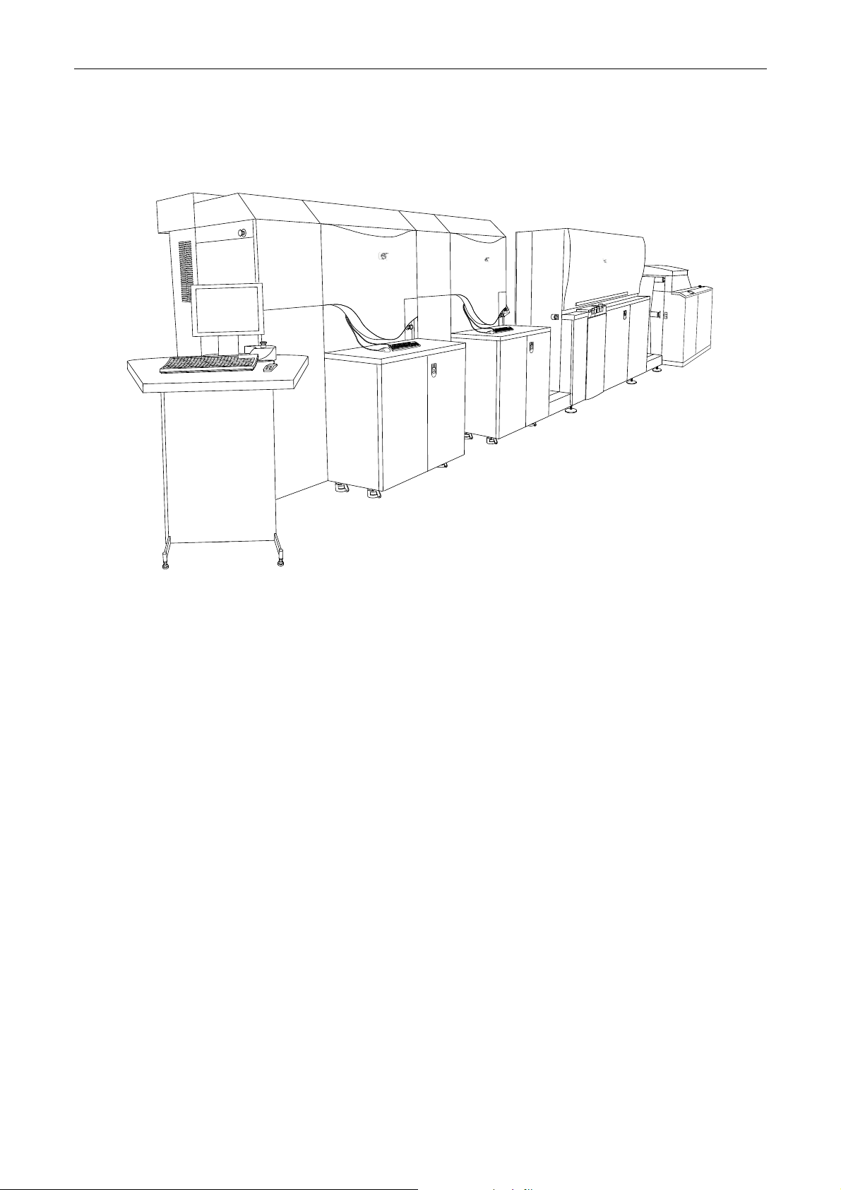
Overview
Figure 1 The HP Indigo press w3250
The procedure to install the HP Indigo press w3250 involves the following main steps:
• Verifying site preparation
• Marking the pressroom floor
• Unpacking the boxes
• Install the electrical cabinets
• Install the printing engines and turnbar
• Install the In-Line Primer (ILP)
• Installing the unwinder
• Install the main electrical cabling
• Install the slave computers and switchboxes
• Install the printing engine vacuum hoses
• Install the cooling water hoses
• Install the floor platform
• Install system components such as ink cabinets, utility cabinets, and writing heads
• Install the master console and computer
• Powering up the press
• Installing the system electrical cabling
• Configuring the press software
• Testing and calibrating press systems
• Performing CATP
CA294-03070 rev 00 page 6 of 153
Page 7

Installation Manual
Warranty disqualifier
The boxes addressed to the customer may be opened only by a qualified HP Indigo Customer
Engineer. Any unauthorized opening of the boxes may void the warranty on the press and its parts.
This manual and the corresponding Quick Reference Checklist are intended for use by the Customer
Engineer. The engineer should obtain the manual prior to the installation of the press.
CAUTION: The HP Indigo press w3250 printing engines,
unwinder and rewinder may be lifted or transported
only by specially trained and qualified personnel
using lifting bars, lifting straps, and other
specialized equipment that meet HP Indigo
specifications as well as any additional
requirements imposed by central and local
government regulations.
Improper lifting may cause serious personal injury
and/or damage to the press or other property.
Do not lift the printing engines (PE) from the paper
input or paper exit side.
When lowering the printing engines from the fork
lift, place wedges on the floor in front of the wheels
to prevent slipping.
The press must be hard connected to the mains by a qualified local electrician in accordance with
local safety regulations. The connection must be through a lockable mains supply disconnect switch
rated at 32 A 5000 AIC type G. The cables must be protected by a conduit.
CA294-03070 rev 00 page 7 of 153
Page 8

Installation Manual
Quick reference checklist
The following procedure is a quick reference guide of the installation procedure intended for two
integrators and extended over five days.
Step
Heading
Reference Procedure
1st Day
Pre-installation
Site
preparation
Measuring
and marking
Unpacking 3. Unpacking the boxes
Installation
Electric
cabinets
(20 mins)
U-bases
(40 mins)
Printing
engines
(160 mins)
1. Verifying site
preparation on page
23
2. Marking the
pressroom floor on
e 23
pag
on page 23
4. Installing the
electrical cabinets on
pag
e 24
5. Position the u-bases
on page 24
6. Position the foresight
stand on page 28
7. Install the junction
bars on page 32
8. Mount the PE2 on
page 33
9. install the platform on
page 43
10. Mounting the turnbar
on page 44
11. Mounting the PE1 on
page 45
12. level each printing
engine on page 46
13. align the printing
engines on page 49
14. Securing the turnbar
on page 54
15. connect the printing
ines on page 56
eng
y site preparation as per Site
Verif
Preparation Guide
Use marker pen to mark profile of press,
cabinets, unwinder, ILP and Finisher on
floor
Unp
ack the boxes and verify their contents
either with the BOM or Packing list on page
17.
Install electrical cabinet M1 and M2 in their
marked position.
n the u-bases on the floor. Adjust
Positio
distance between u-bases to 693.0 mm at
a height of 200 mm. from the floor.
Use surve
accurately. Raise the tripod and surveying
tool to 1550.0 mm.
Install the junction bars between the two ubases.
Mount the PE2 on the u-base. Use the
lifting and positioning assembly.
Install the platform between the printing
engines.
Mount the turn
Mount the PE1 on the u-base. Use the
lifting and positioning assembly.
Leve
of 0.0 ± 0.1 mm
Accuratel
horizontally using the surveying tool.
Mount the front
brackets on the extended shaft of idler 3.
Install using M5 screws at front and rear.
Install collar on idler at rear.
Recheck the alignment using the surveying
tool.
Install front link
Recheck alignment using surveying tool.
Check parallelism between PEs using the
parallel jig. Measure to an accuracy of
0.00 ± 0.01 mm
ying tool to align u-bases
bar assembly to PE1.
l each printing engine to an accuracy
y align the printing engines
and rear connection
brackets to attach two PEs.
Notes and
check
Site Preparation
check list
Marker pen
Cable meter
Packing list
Packed with PE2
CA294-03070 rev 00 page 8 of 153
Page 9

Installation Manual
Step
Heading
Electrical
wiring
(180 mins)
Vacuum
hoses
(40 mins)
Reference Procedure
16. Install the electrical
cabinet-to-cabinet
cables on page 61
17. Install the electrical
cabinet M1 cables to
PE1, PE2 on page 62
18. Install the electrical
cabinet M2 to PE1,
PE2 on page 62
19. Install the electrical
cabinet M1-to-master
console cables on
e 63
pag
20. Install all Unidrive
cables on page 66
21. Install the PE1-toPE2 cables on page
67
22. Install the PROFIBUS
cables as on page 67
23. Install the CTNET
cables on page 68
24. Route the MPI
(MODBUS) cables on
pag
e 69
25. Connect the ProfiBus
and CT
Net cable
connections on page
69
26. Installing the vacuum
hoses on page 70
2nd Day
Floor platform 27. Install the floor
platform on page 72
Install electrical cabinet M2 to cabinet M1
cabling.
Install electrical cabinet M1 to cabinet M2
cabling.
Install electrical cabinet M1 to PE1 and
PE2.
Install electrical cabinet M2 to PE1 and
PE2.
Install the electrical cabinet M1-to-master
console cables.
Leave the cables ends at the cabinet until
installation of the raised floor and master
console.
Install al
electrical cabinets M1 and M2.
Install the PE1-
Install ProfiBus
between electrical cabinets M1 and M2 and
PLC in cabinet M1.
Install CT
at electrical cabinets M1 and M2.
Route the MPI (MODBUS) cable through
the ILP connection panel to the front of
PE1 and connect JTBD of the cable to
PTBD of the TBD.
Route the remaining connector JTBD to the
exit are of PE2 and connect it to PTBD of
the TBD.
Con
cable connections at electrical cabinets M1
and M2
Remov
Install and route all vacuum hoses from
electrical cabinets M1 and M2 to PE1, PE2
(short hoses 2-3 m), and ILP.
Wait for the raised floor and ILP to install
long hose (3-4 m).
Reinstall lower under-panel
Install floor p
specifications in Site Preparation Guide.
Start at unwinder and ILP area. For press,
start at corners of press or wall.
l PE1 and PE2 Unidrive cables in
to-PE2 cables.
communication cable
Net cables between all Unidrives
nect the following ProfiBus and CTNet
e under-panel
latform according to
Notes and
check
Wait for floor and
ILP to connect.
CA294-03070 rev 00 page 9 of 153
Page 10

Installation Manual
Heading
Chiller and
chiller pipes
(60 mins)
UPS
(10 mins)
Writing head
(30 mins)
HVPS
(40 mins)
Roof
(15 mins)
Utility cabinet
top cover
(15 mins)
Various
components
(45 mins)
3rd Day
Lift ILP,
unwinder,
utility
cabinets, ink
cabinets
(20 mins)
ILP
(120 mins)
Step
Reference Procedure
Notes and
check
28. Installing the chiller
on page 72
29. Install the UPS on
e 75
pag
30. Install the writing
head on page 76
31. Install the HVPS on
page 77
32. Install the HVPS on
page 77
33. install on page 117 Install utility cabinet top cover.
34. Install system
nents on page
compo
80
35. Lift and move the ILP,
unwinder, utility
cabinets, and ink
cabinets on page 80
36. Installing the ILP on
page 81
Install chi
connections.
Install chiller according to specifications.
Refer to the UltraFilter ultracool 0400
installation guide:
Flow rate of 56 ±5 liters/minute
Temperature (measured at the press
Make sure that the external filter supplied
by the supplier is installed. The filter should
be installed at the chiller return pipe.
Connect the cooling water hoses to the
press as shown in Figure 53 and Figure 54
(dep
Install and connect the UPS cables.
Cables to be found in cabinet M1.
Check the installation of all UPS cables
between the electrical cabinet M1, PE1,
and PE2.
Connect the cables to the internal battery.
Remov
Remove under-plate at heater window.
Install and align writing head.
Install HVPS units and covers.
Install roof covers.
Install the foll
PTE/air knife.
Scorotron units.
Cleaning station and wiper blade.
ITM cover.
BID units.
Ametek filters.
Lift the ILP, unw
ink cabinets to the raised platform floor.
Position ILP near PE1. Position ILP feed
and exit stepping plate assemblies near
ILP.
ller pipes adapters and
inlet) of 6°C
ending on country of installation).
e writing head from box 8.
owing in each engine:
Thoroughly clean the BID units.
inder, utility cabinets, and
Hoses from chiller
should be prepared
CA294-03070 rev 00 page 10 of 153
Page 11

Installation Manual
Heading
Unwinder
(60 mins)
ILP wiring and
air hose
connections
(160 mins)
Step
Reference Procedure
Notes and
check
37. install the ILP exit
stepping plate on
pag
e 83
38. align the ILP and
stepping plate
assembly on page 86
39. Measure on page 87 Measure distance between stepping plate
40. Release on page 88 Release (do not remove) six ILP alignment
41. Lower on page 88 Lower four ILP feet until castors
42. level and align the
ILP on page 89
43. align the ILP on page
93
44. level and align the
ILP exit stepping
plate rollers on page
94
45. Install the ILP feed
stepping plate on
pag
e 96
46. install the priming
rollers on page 99
47. Installing the
unwinder on page
100
48. align the unwinder on
page 103
49. Unwinder electrical
conn
ections on page
104
50. ILP electrical
connections on page
105
51. Install on page 105 Install cables between cabinet M1and the
52. Connect on page 105 Connect air hoses and cables to the ILP
53. Install on page 106 Install the cable securing clamps on the
Install the ILP exit stepping plate assembly
to the ILP.
Align the ILP and stepping plate assembly
with the press. Verify gap between ILP exit
cover and web entrance cover at PE1 is
approximately 4-5 mm.
front edge and PE1 front wall. Distance
should measure 30 mm.
plate locking screws.
approximately 5 mm above floor platform
and feet touch floor.
Leve
l the the ILP
Align the ILP using the parallel jig.
Level and align the ILP exit stepping plate
rollers.
Install the ILP feed stepping plate. Align
and level the stepping plate to the ILP.
Install the ILP primin
n, install, level and align the
Positio
unwinder.
Align the unwinder with the ILP feed
stepping plate.
Install an
and air hoses.
Install cab
panel and cabinet M1.
ILP connections panel
connections panel
clamp rail.
d connect all appropriate wiring
les between the ILP connections
g rollers
CA294-03070 rev 00 page 11 of 153
Page 12

Installation Manual
Step
Heading
Ink cabinets
(90 mins)
Web guide
(10 mins)
Utility
cabinets
(20 mins)
Computers
installation
(40 mins)
Reference Procedure
54. Connect on page 108 Connect the following air hoses at the ILP
55. Install the ILP rear
panel safety cover on
e 111
pag
56. Install the ILP
vacuum hoses on
pag
e 112
57. Installing the ink
cabinets on page 113
58. Place on page 116 Mount and install the corian working
59. Adjusting the web
de on page 116
gui
60. Install the utility
net on page 117
cabi
61. Connect the
computers on page
121
62. Install the computer
cables on page 126
63. Install the master
le on page 127
conso
front:
Input hose from mains air supply to
Inlet connection.
Long outlet hose from Outlet to PE
connection to PE1.
Long outlet hose from Outlet to UW
connection to unwinder.
Install safety cover at the ILP front.
Connect the vacuum hose to the ILP.
Install eac
order shown in Figure 93 on page 113 for
four colors, and Figure 94 on page 113 for
seven colors.
If more than four colors to be
make sure that relevant calibration kit is
ordered for extra colors.
surface.
Mount the mo
on working surface.
Remov
adjust the web guide.
Customer to save screws.
To troubleshoot, refer to w3200 service
manual Calibrations.
Install the util
hoses from utility cabinets to the printing
engines.
Cooling water in
Cooling water out
Solid add compressed air
Impression drum cooling drain
Vacuum
Air flow
Connect control cable and power cable to
utility cabinets.
Check the n
Figure 103, and Figure 104 on page 121 -
122.
Install Slav
electrical cabinet M2.
Install the com
computers.
Install master c
master computer.
h ink cabinet according to color
installed,
nitor, keyboard and mouse
e the two securing screws and
ity cabinets and connect
etwork diagrams in Figure 102,
es 1 and 2 computers in
puter cables to both slave
onsole, and connections to
Notes and
check
CA294-03070 rev 00 page 12 of 153
Page 13

Installation Manual
Heading
Production
flow
4th Day
Rewinder jig
and finishing
components
Turnbar
stepping plate
Transformer
Initial
power-up
Thread web
Configure
press
PIP and
blankets
5th Day
ATP
Step
Reference Procedure
64. Production flow on
page 130
65. Install the finishing
components on page
130
66. Installing the turnbar
ng plate on
steppi
e 130
pag
67. Install the main power
conn
ection and
transformer on page
130
68. Initial power-up on
e 131
pag
69. Threading the web on
e 138
pag
70. Configure the press
software on page 139
71. Install PIP and
blankets on page 139
72. Testing and
calibrating the press
on page 139
Emergency stop tests on page 139.
Checking the web flow on page 140.
Checking the ILP priming unit on page 140.
Testing the printing engine on page 141.
Testing printing engine voltages on page
Performing integration and testing on page
Organize and install network cabling, RIP
systems, HPPF units to aid production
flow.
Install the re
After testing, install finishing components
according to customers design and Site
Preparation Guide.
Install turnbar stepping plate.
A local qualified electrician should install
and connect the transformer and electrical
mains power connections.
Perform initial power up as detailed on
page 131.
Local electrician to be present at startup to
check mains power connections.
Mount a roll at unwinder and thread to
finisher according to
Install latest version of press soft
authorization codes.
Mount an
relevant drums.
Test and calibrate press:
In the Diagnostics>Elements Ink Flow
tab perform tests
142.
143:
1.
2. Verify that the ink flows.
3. Verify that the second transfer
4. Install a new blanket and PIP foil.
5. Adjust the BID pressure.
6. Perform the first transfer pressure
7. Verify the writing head skew.
Changing the skew may affect focus.
winder jig to test the press.
ware with
d install PIP and blankets on
Build the inks.
pressure is correct.
calibration.
Notes and
check
CA294-03070 rev 00 page 13 of 153
Page 14

Installation Manual
Heading
Step
Reference Procedure
Notes and
check
8. Verify the writing head focus.
9. Verify the accuracy of the front to
back and side to side prints:
a. Perform the natural web length
calibration for duplex. See HP
Indigo Service Instruction
Calibrations,
MNU-1633-01.
b. Perform the eye mark sensor
vertical positioning. See HP
Indigo Service Instruction
Calibrations, MNU-1633-01.
c. Perform the eye mark sensor
lateral positioning. See HP Indigo
Service Instruction Calibrations,
MNU-1633-01.
d. Perform the eye mark distance to
nip adjustment. See HP Indigo
Service Instruction Calibrations,
MNU-1633-01.
e. Make sure that the substrate is
centered at PE1. Print and check.
f. Make sure that the substrate is
centered at PE2. Print and check.
10. Perform color adjustment using the
paper roll supplied with the press.
If a different substrate is to be
installed on the press, perform the
following:
a. Load glossy paper on the press.
b. From the Adjustments menu,
click Color Adjustment &
Calibration.
The Color Adjustment Wizard
Manager window opens.
c. In the Automatic Color
Adjustment area, click Custom
Color Adjustment.
The Custom Color Adjustment
wizard opens.
d. Select the desired matrix.
e. In the Electrode Voltage
Calibration field, select Include
Velectrode Calibration.
f. Click Next. The OD step opens.
g. In the Select Method of Substrate
OD Usage field, select Read
Substrate OD.
CA294-03070 rev 00 page 14 of 153
Page 15

Installation Manual
Heading
Step
Reference Procedure
Notes and
check
h. Click Next and Print.
The color adjustment is
performed.
Make sure that the wizard
completes all of its steps, and that
all colors pass the color adjust
procedure.
i. Click Finish.
j. Load the desired substrate on the
press.
k. Print the CATP job.
l. In the 9th and 10th copy of the
CATP printout, measure the solid
patches (J area), and calculate
the average values.
Note the values.
m. Change the press software to
technician mode.
n. From the Options menu, click
Systab Editor.
The Systab editor window opens.
o. Expand the mmiCATopic tree.
p. In the right window, double-click
SpecOdLowerDeltaOsm.
The mmiCATopic
SpecOdLowerDeltaOsm window
opens.
q. In the Saved field, type -0.7.
r. Click OK. The window closes.
s. Double-click
SpecOdLowerDelta5.
The mmiCATopic
SpecOdLowerDelta5 window
opens.
t. In the Saved field, type -0.7.
u. Click OK. The window closes.
v. Close the Systab Editor.
w. From the Adjustments menu,
click Color Adjustment &
Calibration.
The Color Adjustment Wizard
Manager window opens.
x. In the Automatic Color
Adjustment area, click Custom
Color Adjustment.
The Custom Color Adjustment
wizard opens.
y. In the Electrode Voltage
Calibration field, make sure that
Include Velectrode Calibration is
not selected.
z. Click Next. The OD step opens.
CA294-03070 rev 00 page 15 of 153
Page 16

Installation Manual
Step
Heading
COI 74. Complete the
Reference Procedure
Testing during normal operation on page
73. CATP on page 145 Perform CATP test procedure:
Printing CATP test on page 147.
Check CATP against CATP specification
installation on page
150
aa. Click Setup.
The Setup OD of 100% Spec
Values window opens.
bb. Enter the optical density values
noted in step l above in the
opriate color fields.
appr
cc. Click OK.
A warning may appear. Click OK
to close the warning.
dd. In the wizard, complete the wizard
steps.
Make sure that the color
calibration is completed
successfully.
ee. From the Diagnostics menu,
click Writing Head.
The Writing Head window opens.
ff. Click the Laser Power tab.
gg. Check that the Laser Power
values do not approach the upper
or lower limits (30 to 1).
If the values are at either
extremity, perform the Machine
LUT Calibration wizard from
Adjustments > Machine LUT
Calibration.
11. If necessary, perform the Machine
LUT using 180 lpi.
145.
checklist on page 147.
Compl
ete installation as detailed on page
150.
Notes and
check
CA294-03070 rev 00 page 16 of 153
Page 17

Installation Manual
General information
How to use this manual
Read the manual carefully prior to installing the press. This manual is intended to guide the CE
throughout the installation of the press.
The packing list in the boxes takes priority over the list in this manual. Check off parts against the
packing list in the boxes.
The Quick Reference Installation Guide at the end of the document is intended to provide the
experienced installer with reminders of the key steps and information.
Packing list
The table below lists the main contents of each box. The full contents list provided with the boxes
takes priority over this table.
Box no.
1
2
3 MPQ-0620-51 U-base assembly 2 U-base
4
5
6 CA290-0523X Vacuum hose pipes kit for
7
Part number Contents Qty Name and weight (kg)
CA254-01592
CA294-03070
CA254-00322
CA271-00263
EBC-3005-01
CA290-05140
MPQ-0024-33
MSQ-0017-02
MJX-2427-51
MZH-0328-02
CA290-05130
MPQ-0024-33
MSQ-0017-02
MZH-0328-02
MPT-3515-54
MPT-8636-51
EAS-2041-52
MPT-2609-55
MKT-3354-02
MPT-6787-53
MPQ-0028-01
MZH-0333-06
MPT-7387-52
WHS electrical cabinet M1b
Keys
Installation Manual
WHS electrical cabinet M2b
Keys
Computer Slave #1 and #2
Network Ethernet SW1
Printing engine 2 (PE2)
Working surface
Leveler 75x150-55 Airloc
Fixing bracket assembly
Pipe Insulation 1-1/8”
Printing engine 1 (PE1)
Working surface
Leveler 75x150-55 Airloc
Exit inverter roller
Pipe Insulation 1-1/8”
w3250
Back right cover assy
Roof top cover assy
HVPS assy
Utility cabinet
Kit ink cabinet- s3200
Cover t4
Cover guide closure (stage)
Pipe flex od-1+5/16
Bottom cover for pub
1
3
1
1
4
2
2
1
1
4
2
1
1
1
4
1
1
1 Vacuum pipes kit for w3250
1
1
2
1
1
2
1
2
1
Electric Cabinet
Electric Cabinet
PE2 engine
PE1 engine
Miscellaneous PE2
CA294-03070 rev 00 page 17 of 153
Page 18

Installation Manual
Box no.
8
9
10
11
12
Part number Contents Qty Name and weight (kg)
CA245-15320
CA290-00121
CA245-00132
CA245-00332
MPT-3989-51
CA245-09891
MPT-3515-54
MPT-8636-51
MPT-2609-55
MKT-3354-02
CA270-00101
CA290-06290
CA290-05260
CA297-00350
MPK-3072-05
MPQ-0028-01
CA244-05941
CA245-08182
CA245-08352
CA245-01234
CA240-47210
CA245-16791
CA245-04963
5188-1250
CA240-60860
5188-4872
PX848AA#ABB
MPT-7383-53
CA271-00263
DD817AV
MPT-7646-32
EHE-4069-51
CA261-07420
CA248-00230
DD837AV
SRO-0070-01
MNU-1050-82
EMS-2008-81
CA290-05580
Air Knife
Kit S/P Cleaning station and
wiper
Scorotron
BID unit
Filter box assembly
Arms, Cover holder assembly
Back right cover assembly
Roof top assembly
Utility cabinet
Kit ink cabinet
Writing head assembly for u\s
Kit acc. Installation For w3250
Kit access for w3250
Sp UPS w/extension cables
Skid pallet
Cover guide closure (stage)
Keyboard & mouse
Screws M8x40, flat
Washers, Spring Washers
Cover for left ramp
Left ramp assembly – ILP
Right ramp assembly -ILP
ILP
Air pipe black dia.=12
Upper rubber roller assy
ILP, lower roller assy
UW6 - Unwinder for w3250
Pipe air 8mm
Panel front
Perspex covers for uw6
Feed roller
Unwinder book
Monitor
Console assy
Emergency stop panel
Computer
Keyboard ps/2 hp
Working surface master
console
Cable assy cc69
Cable assy cc70
PC software kit
Mouse PS/2 HP
Siemens software
Machine system info
Mouse pad
Kit S/W 6.7 w3250
1
2
6
8
2
2
1
1
1
1
2
1
1
2
1
1
2
8 of
each
1
1
1
1
2
2
2
1
1
1
1
1
1
1
1
1
1
1
1
1
1
3
1
1
1
3
1
Miscellaneous PE1
Ramp
ILP
Unwinder
Master Console
CA294-03070 rev 00 page 18 of 153
Page 19
Installation Manual
Box no.
13 Q5391-00680 Kit cons. Instl. W3250 1 Consumables kit
14 MPR-1309-11 Pap. Roll condat 115 1 Paper roll condat 115
Part number Contents Qty Name and weight (kg)
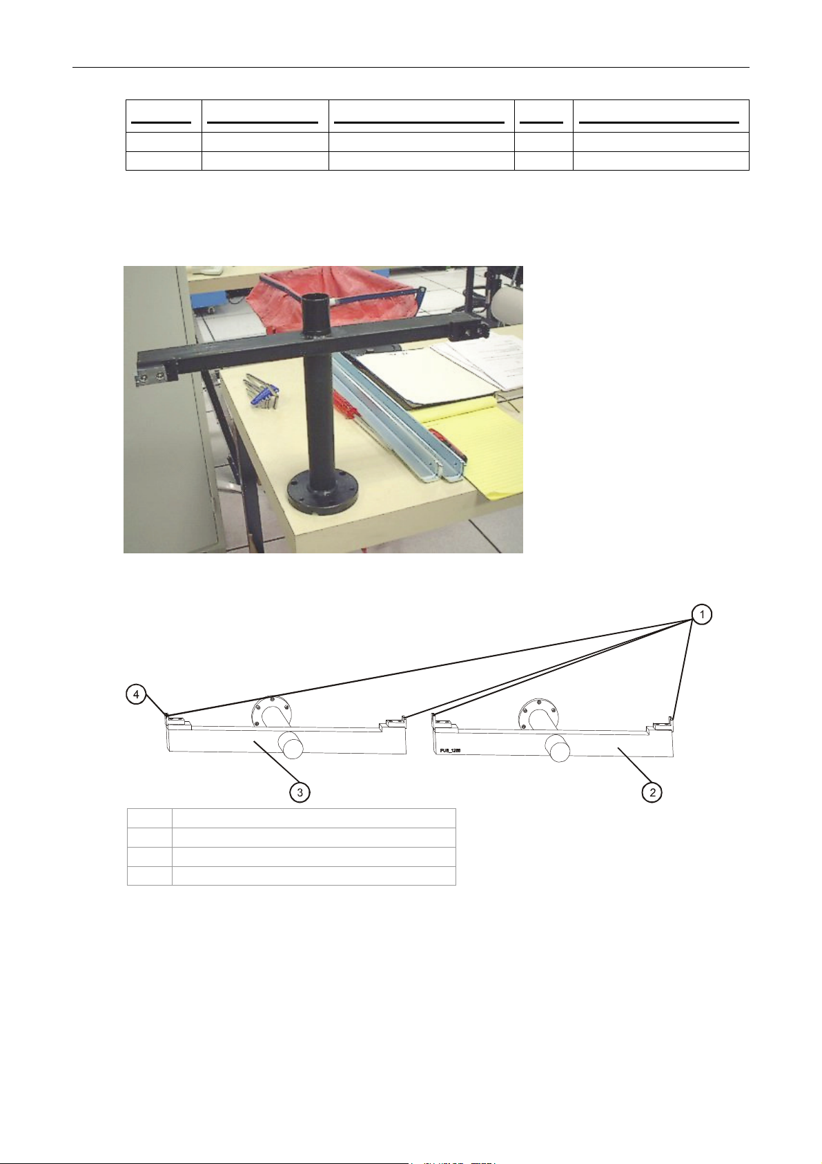
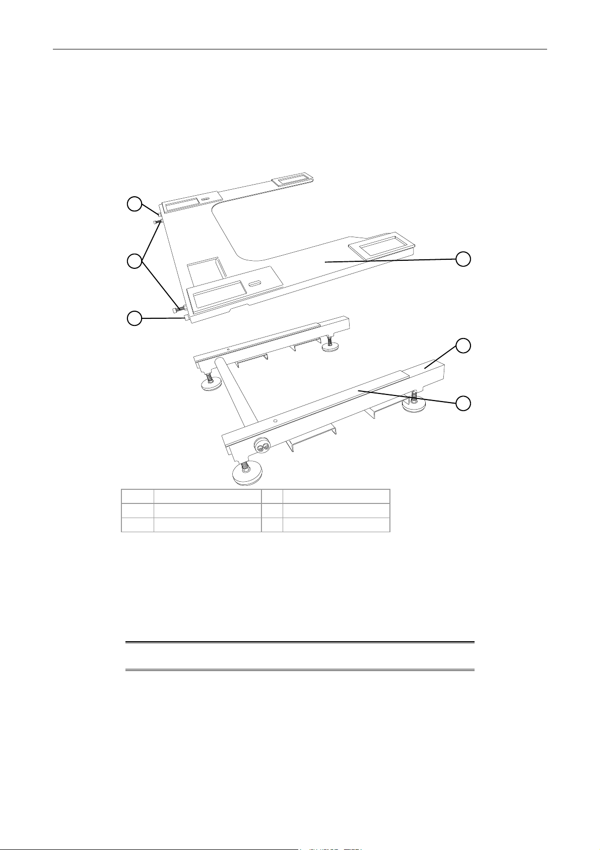
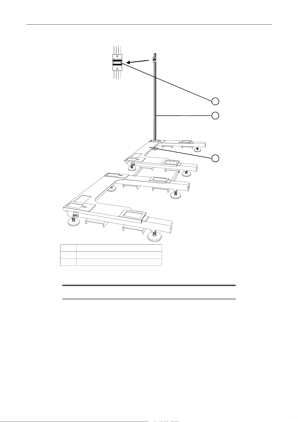
The alignment jig
Figure 2 The alignment jig
Figure 3 The alignment jigs mounted
1 Sights increasing in height from PE1 to PE2
2 PE1 jig
3 PE2 jig
4 Highest sight
Alignment jigs are used to adjust the forward/rearward alignment of the printing engines.
The jigs are used with a surveying tool (scope). They are not identical. When mounted properly, the
sights on the jigs increase in height going from PE1 to PE2. The increase in height allows all the sites
to be visible in the surveying tool. Adjustments can then be made to the position of the printing
CA294-03070 rev 00 page 19 of 153
Page 20
Installation Manual
engines until all the sights are lined up with the crosshairs in the surveying tool (Figure 2 and
Figure 3).
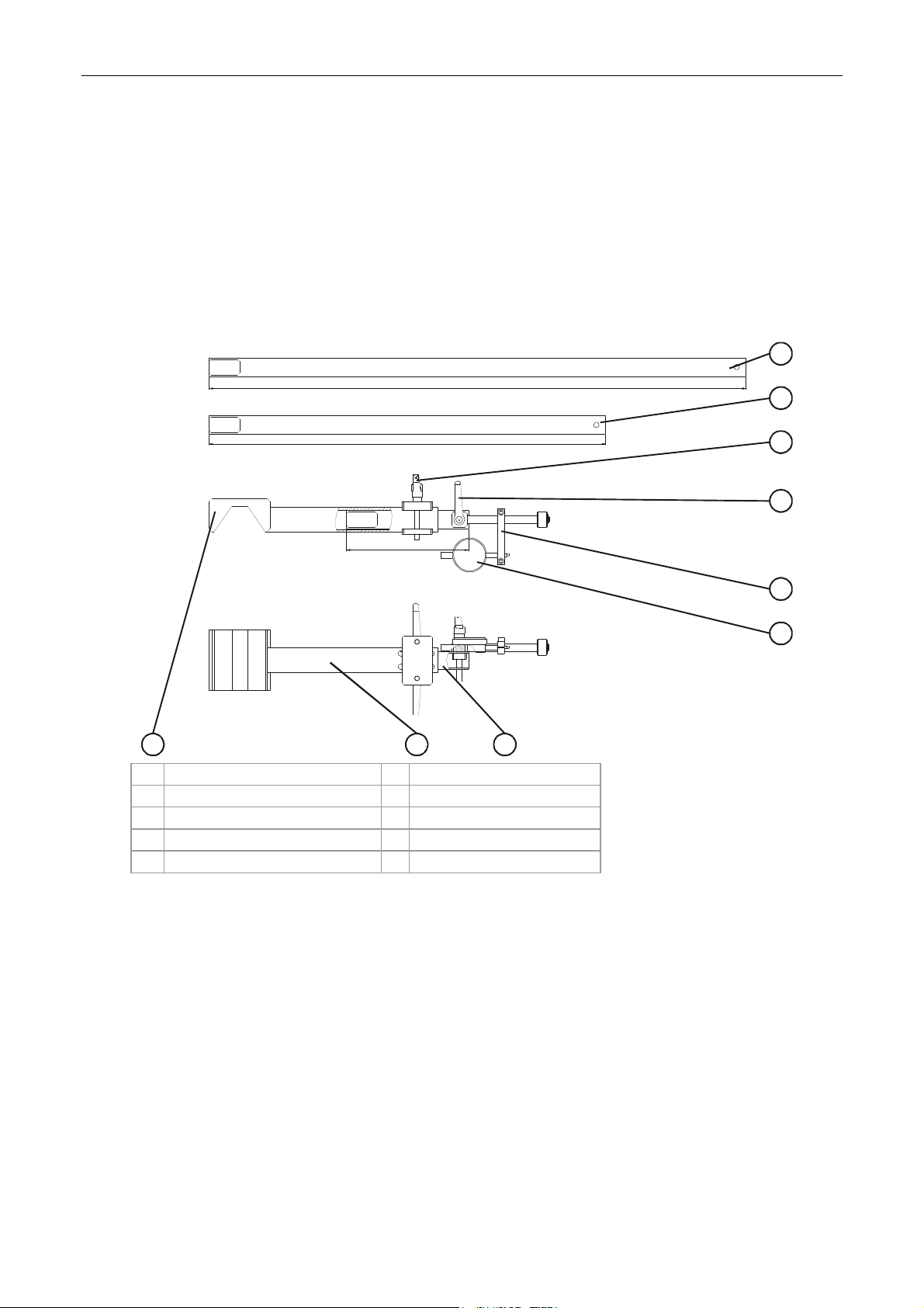
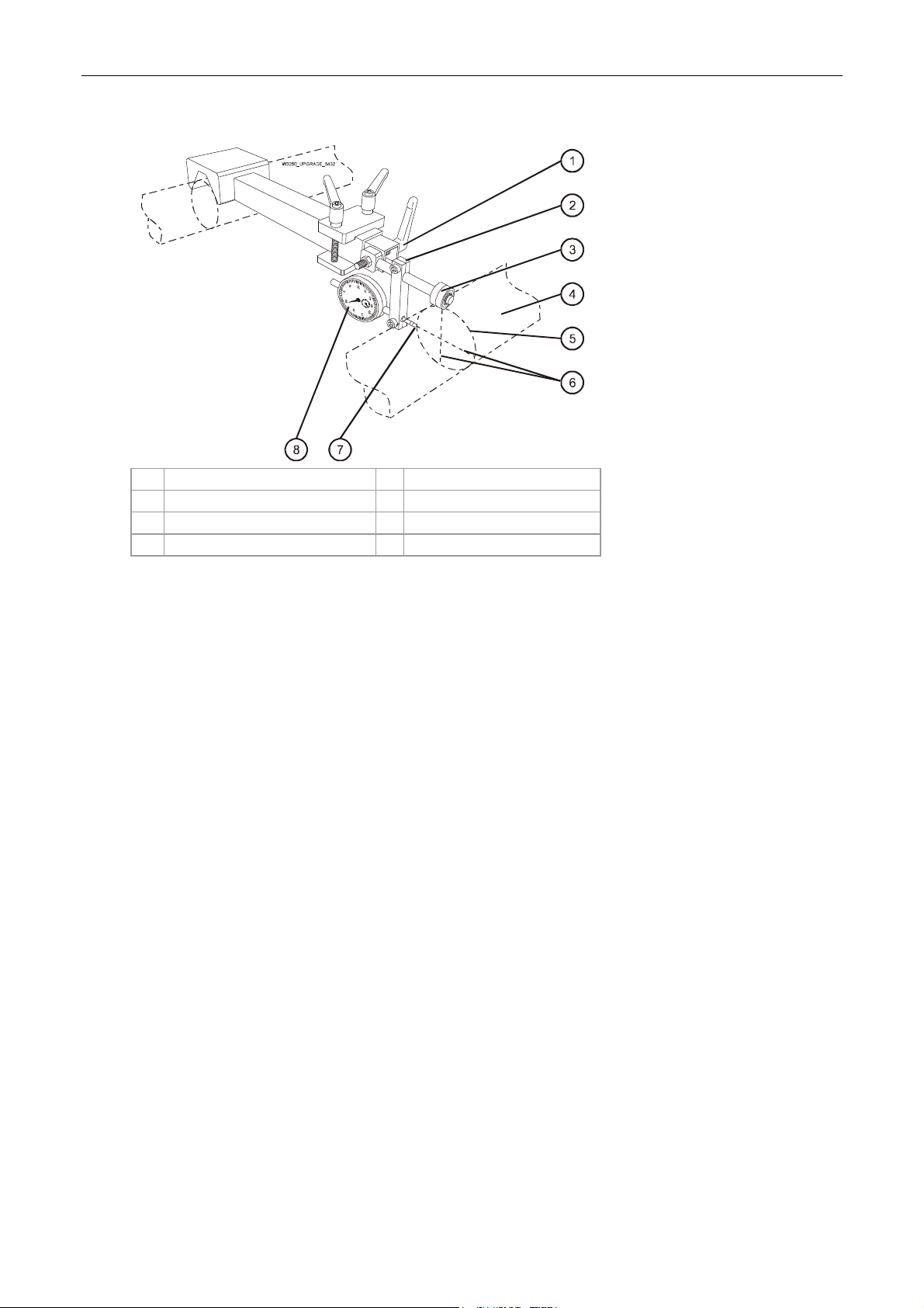
The parallel jig
The Parallel jig measures the variation in distance (parallel) along the length of two rollers. It is used
to accommodate the various adjustments necessary to bring the rollers of all the press components
(printing engines, ILP, unwinder) into parallel with the rollers of the adjacent one. Adjustments can
then be made to the press component position until the variation in distance is either zero or minimal.
Figure 4 Sections of the new Parallel jig
880
650
200
9
1 880 mm long extension 6 Dial
2 650 mm medium extension 7 Base
3 Extension securing screw 8 200 mm short extension
4 Dial bracket securing screw 9 V-section
5 Dial bracket
87
1
2
3
4
5
6
The jig may be extended between rollers of distances using the three extensions which are attached
to the base. The v-section is suitable for rollers of diameter 50 - 79 mm, whereas the dial bracket,
buffer and dial are suitable for rollers 79 - 80 mm in diameter (Figure 4).
The long
•
configuration is used to make the following alignments (Figure 4):
To align the ILP to PE1
• To align the unwinder to the ILP
The intermediate configuration is used to make the following alignments (Figure 4):
•
To align one of the rollers in the exit-side stepping plate of the ILP to PE1
• To align one of the rollers in the input-side stepping plate of the ILP to the ILP itself
CA294-03070 rev 00 page 20 of 153
Page 21
Installation Manual
The short configuration is used to align the remaining roller in each stepping plate to its companion
roller aligned previously (Figure 4).
To assem
1.
ble the new Parallel jig to align two rollers (Figure 4):
Insert the measuring gauge fixture into the desired extension (long, intermediate, short).
Tighten the handle.
2. Insert the extension into the base so that the V-section and the gauge are facing the same
direction.
Tighten the two handles to secure the extension.
NOTE: Disassembly is the reverse of the above two steps.
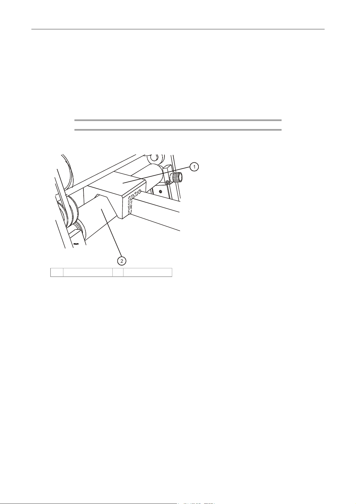
Figure 5 Mounting the v-section of the Parallel jig
1 Base v-section 2 Roller
3. Mount the v-section on the first roller (Figure 5).
Make sure that the extension reaches the second roller and tighten the extension securing
screws.
CA294-03070 rev 00 page 21 of 153
Page 22
Installation Manual
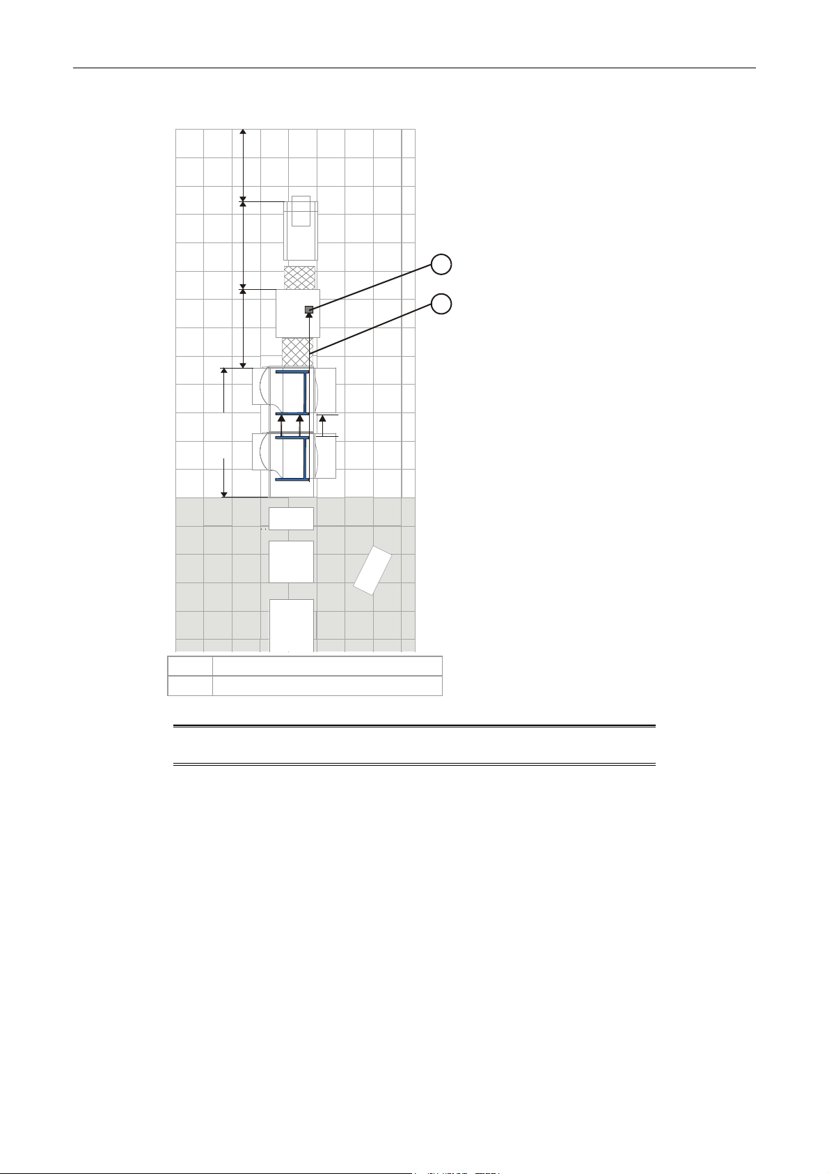
Figure 6 Mounting the dial bracket on the extension
1 Dial bracket securing screw 5 Positioning circle
2 Dial bracket 6 Center lines of roller
3 Buffer 7 Position of dial sensor tip
4 Roller 8 Dial
4. Mount the gauged end of the jig on the specified roller needing to be aligned.
5. Loosen the screw securing the gauge support on the fixture, and slide it back so it does not
interfere with placing the wheel.
6. Loosen the lock nut for the handle securing the gauge fixture in the extension.
7. Adjust the position of the gauge fixture in the extension so that the wheel rests on the roller
and coincides with the vertical centerline of the roller.
Tighten the handle and the lock nut.
8. Slide the gauge support back until the contact touches the roller.
Continue sliding the gauge until the needle makes one complete turn.
Tighten the screw to secure the gauge support in place.
Prerequisites
Completion of site preparation.
Estimated installation time
4 days
Special skills
Only specially trained personnel should perform this installation.
Special jigs and tools
All special jigs and tools required for the installation of the press are included in the installation kit.
Confirm the contents of the installation kit with the Bill of Materials (BOM).
CA294-03070 rev 00 page 22 of 153
Page 23

Installation Manual
Pre-installation procedure
Verifying site preparation
Verify that the pressroom has been equipped with the following per the HP Indigo press w3250 site
preparation guide:
Chiller input and output
Power for press
Air conditioning of work area
Fast Ethernet networking
Parts cleaning station
External densitometer
Lockable main switch
Electrical outlets installed near pluggable equipment and are easily accessible
The printing engines may be mounted on the u-bases on-site or off-site. Make sure that the entrance
to the site is large enough to allow an object 2200 mm high to enter.
Marking the pressroom floor for press components
1. Open the installation kit and select the marking pen.
2. Use the marking pen to mark the pressroom floor with the profile of the main press
components and indicate their placement. Refer to the HP Indigo press w3250 site
preparation guide for details of the floor area.
Unpacking the boxes
1. Before opening the boxes, check that the shock and tilt sensors have not changed color to
red. If either of the sensors has changed color to red, then the boxes were mishandled. Notify
the Regional Service Manager or Installation Manager immediately.
2. Unpack the box containing the accessories kit.
Open the accessories kit, and remove the System Information File.
Remove the customer letter about residual ink (P/N SV8-0039-00) from the System
Information File.
3. Give the letter to the customer.
4. The boxes are opened in the order of installation. At each stage of the installation open each
box carefully and inspect the part for damage before installing. If any part shows signs of
damage, immediately notify the Response Center or Regional Service Manger.
Verify the contents of each box according to the contents list included with the boxes.
5. Notify the Regional Manager or Installation Manager regarding any installation problems or
damage found when unpacking the boxes.
CA294-03070 rev 00 page 23 of 153
Page 24

Installation Manual
Procedure
NOTE: Two persons are required for this installation.
Installing the electrical cabinets
1. Place electrical cabinet M1 and electrical cabinet M2 in their positions.
2. If any of the finishing components include electrical cabinets, position that cabinet opposite its
corresponding finishing component and in line with the main electrical cabinets.
Installing the printing engines
Positioning the printing engines
1. Position the u-bases as follows
a. Unpack the u-bases and loosen the front two securing screws to remove the u-base
slip plates.
Place the slip plates aside for later use.
CA294-03070 rev 00 page 24 of 153
Page 25
Installation Manual
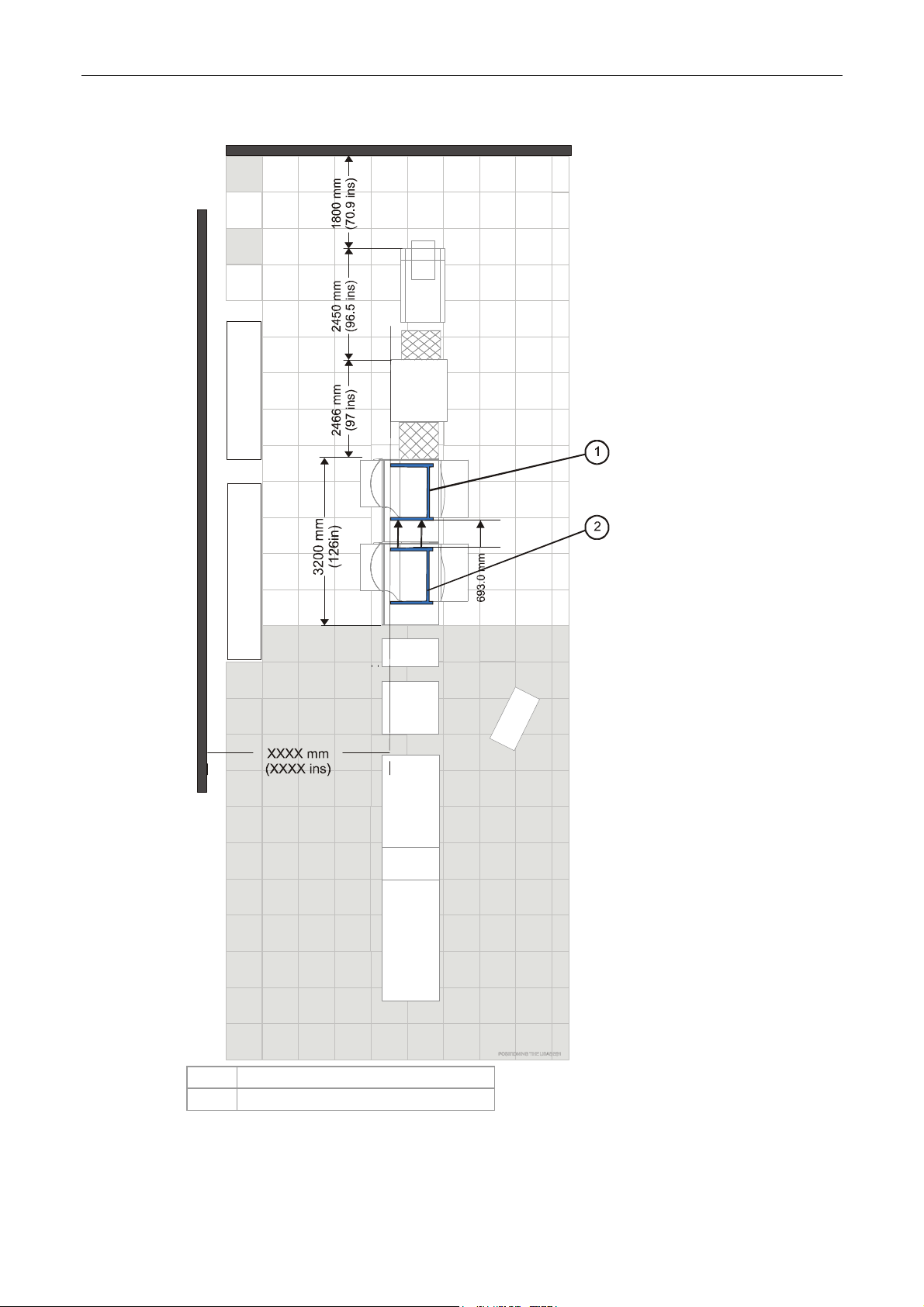
Figure 7 Positioning the u-bases
1 PE1 u-base
2 PE2 u-base
CA294-03070 rev 00 page 25 of 153
Page 26
Installation Manual
b. Lay the u-bases on the floor at a distance of 6716 mm (1800+2450+2466 mm
(264.4 ins)) from the wall at the unwinder end and at a distance of 693.0 mm
(27.3 ins) apart (Figure 7).
. Measure a distance of XXX mm (XXX ins) from the rear of the u-base to the wall at
c
the electrical cabinets.
Figure 8 Remounting the u-base slip plates
4
5
4
1 U-base slip plate 4 Securing screws (2)
2 U-base 5 Adjustment screws
3 Grease applied here
1
2
3
d. Remount the u-base slip plates on the u-bases (Figure 8).
Grease the u-bases before mounting the u-base slip plates.
The grease facilitates easy adjustment during the aligning procedure.
e. Secure the slip plates with the outer screws.
NOTE: The inner screws are for adjusting. They move the slip plate
from front to rear a total of 10.0 mm.
CA294-03070 rev 00 page 26 of 153
Page 27

Installation Manual
Figure 9 Adjusting the u-base height
1
2
3
4
1 U-base
2 U-base slip plate
3 Height of 200.00 mm
4 Height adjustment screw
f. Adjust the u-base feet to give a height of 200.0 mm from the floor to the u-base top
side (Figure 9).
CA294-03070 rev 00 page 27 of 153
Page 28
Installation Manual
Figure 10 Placing the foresight on the PE2 u-base
5
1 12 23 34 45
0.5 mm
0.5 mm
1
2
3
PUB_1596
1 Sight
2 Foresight stand
3 PE2 u-base
g. Position the foresight stand on the PE2 u-base at the front left corner (Figure 10).
NOTE
: The initial position of the foresight stand is used as the
reference for leveling both u-bases.
CA294-03070 rev 00 page 28 of 153
Page 29
Installation Manual
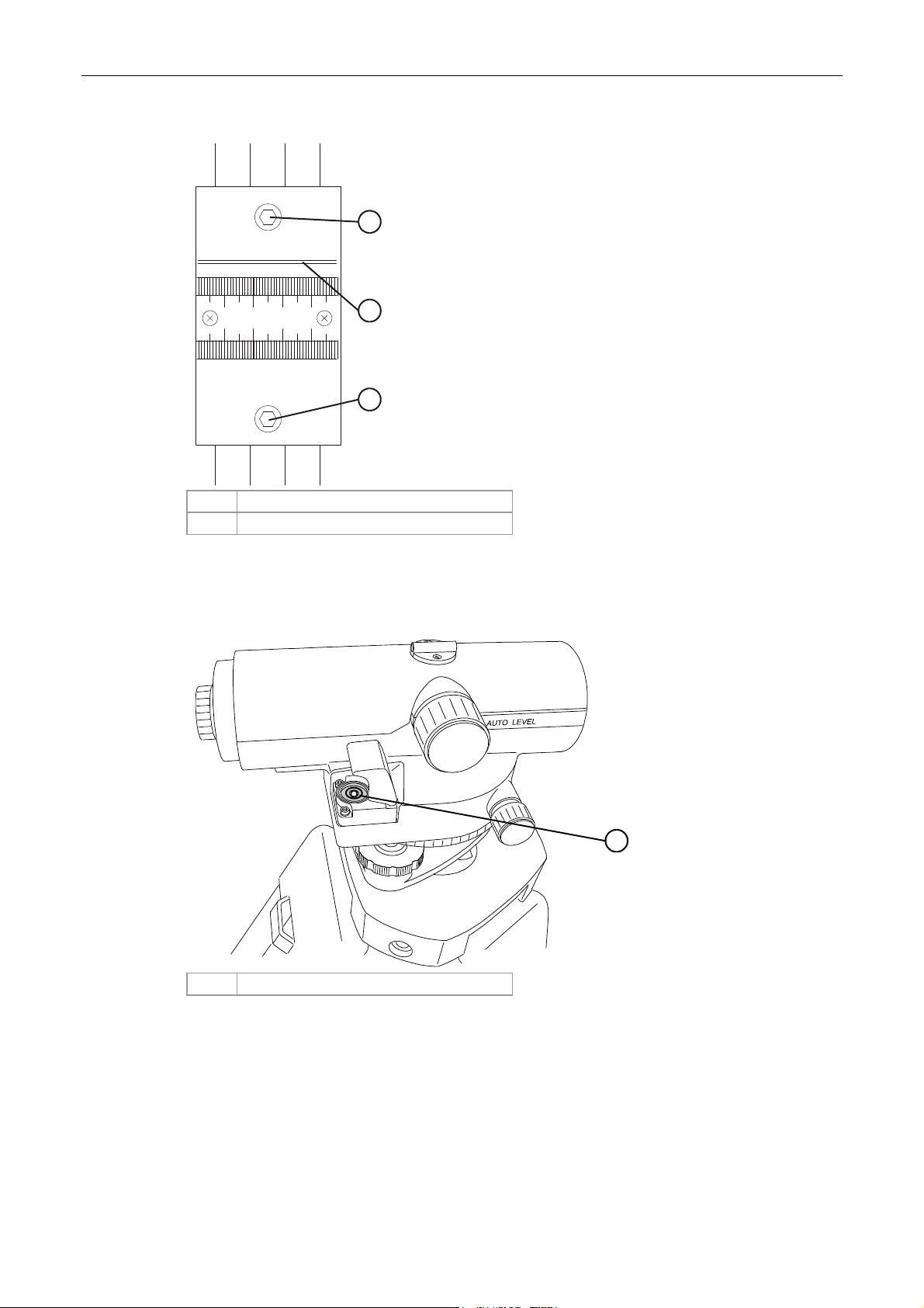
Figure 11 Setting up the surveying tool
XXX
1
2
(125in)
3175 mm
693.0 mm
1 Position of surveying tool
2 Surveying line
NOTE: The surveying tool is setup on its tripod in accordance with
its instruction manual at the position shown in Figure 11.
h. Raise the height of the tripod and surveying tool to 1550.0 mm.
CA294-03070 rev 00 page 29 of 153
Page 30
Installation Manual
Figure 12 Focusing the surveying tool on the foresight stand target
1
2
1234
0.5 mm
5
1
1 Height adjustment screws
2 Crosshair target
i. Position the surveying tool facing and parallel to the foresight stand (Figure 12).
Figure 13 L
1 Level bubble
eveling the surveying tool
PUB_1346
1
j. Adjust the level of the surveying tool until the bubble is centered in the level
(Figure 13).
k.
Focus the surveying tool so that the cross target on the foresight is clearly seen and
centered with the crosshairs of the surveying tool (Figure 11).
If necessary, adjust the height of the cross target on the foresight stand.
CA294-03070 rev 00 page 30 of 153
Page 31

Installation Manual
l. Tighten the lock nut to secure the height of the u-base foot at that corner.
m. Move the foresight stand to the next corner facing the surveying tool.
Adjust the height of the u-base foot at this corner so that the foresight cross target is
centered in the crosshairs of the surveying tool.
n. Repeat step m for all the corners of the u-bases.
Tighten the u-base foot lock nuts at each corner after it is leveled.
o. Recheck all the corners to confirm the heights. Re-adjust if necessary.
p. Use a marker pen to mark the position of the u-base feet on the floor.
Figure 14 Loosening the u-base connecting rods
1
PUB_455
1 Connecting rod
q. Loosen the four screws securing the connecting rod of each u-base (Figure 14).
Figure 15 Installing the j
unction bars between the u-bases
1
2
3
4
1 Junction bars 3 Junction bar securing screws
2 PE1 u-base 4 PE2 u-base
CA294-03070 rev 00 page 31 of 153
Page 32

Installation Manual
r. Install the junction bars (P/N MJX-1852-01) between the two u-bases using two M6
Allen screws, spring washers and flat washers to secure each bar (Figure 15).
NOTE: Make sure to mount each PE to the correct u-base. PE1 has
The lifting jig should only be used if a forklift is either
The distance between the u-bases is now fixed at 693.0 mm.
a web feed door. PE2 has a web exit door.
unavailable or the site does not allow entry to a forklift.
CAUTION: Each section of the lifting jig has a diagram label
describing the position of the section when lifting
the press. Use each specific section in its correct
position as labeled.
Make sure to adhere to all the safety warnings
labeled on the lifting jig. The lifting jig should only
be used on horizontal surfaces and the maximum
lifting weight for the jig is 1800 Kg.
CA294-03070 rev 00 page 32 of 153
Page 33

Installation Manual
Figure 16 Removing the front exit service door
1 Remove these screws
2 Door lower hinge
3 Front exit service door
2. Mount the PE2 on the u-base as follows:
At PE2
a. Remove the three screws securing the upper shaft of the front exit service door
frame.
b. Remove the door by lifting it out of its frame.
CA294-03070 rev 00 page 33 of 153
Page 34

Installation Manual
c. Remove the three screws securing the front exit door lower hinge (Figure 16).
Keep the hinge and screws for later reinstallation.
Figure 17 The lifting and positioning assembly
1 Orientation labels 6 Link bar
2 Support wedges 7 Maximum lifting weight label
3 Pneumatic gun connector /adapter for wheel jack 8 CE label
4 Wheel jack 9 Support wedges
5 Warning label
For use on horizontal surfaces only
CAUTION: Do not use a pneumatic gun to raise or lower the
wheel jack.
CA294-03070 rev 00 page 34 of 153
Page 35

Installation Manual
Figure 18 Positioning the link bar under the feed side
1 Engine rear 4 Positioning label
2 Base frame 5 Feed link bar
3 Support wedges
d. Position the feed link bar under the base frame (Figure 18).
Make sure to insert the support wedges under the engine feed base frame.
CA294-03070 rev 00 page 35 of 153
Page 36

Installation Manual
Figure 19 Positioning the link bar under the exit side of the engine - view from rear
1 Rear electronic cabinet door 5 Support wedge
2 Support wedge 6 Exit link bar
3 Positioning label 7 Exit base frame
4 Rear engine frame
e. Fully open the rear electronic cabinet door (Figure 19).
f.
Position the exit link bar under the exit engine frame (Figure 19).
Make sure to insert the support wedges under the exit base frame (Figure 19).
CA294-03070 rev 00 page 36 of 153
Page 37

Installation Manual
Figure 20 Positioning the lifting frames against the engine
1 Engine frame 5 Metal securing peg
2 Rear lifting frame 6 Lifting frame slot securing end of exit link
bar.
3 Front lifting frame 7 Metal securing peg
4 Lifting frame slot securing end of feed link bar
g. Position the front and rear lifting frames against the engine so that the feed and exit
link bars are inserted in the lifting frame slots (Figure 20).
h.
Make sure that the link bars are inserted sufficiently to the lifting frame slots so that
metal securing pegs can be fully inserted to the holes between the link bars and the
lifting frames.
i. Insert the metal securing pegs to the holes between the link bars and the lifting
frames.
j. Turn each wheel jack (Figure 17) at the four corners of the lifting frames an equal
numbe
r of turns, in steps of 3-4 turns, to raise the engine 20 cm.
This will allow mounting of the engine on the u-base (Figure 17).
CAUTION: Do not tilt the press, as this could cause the press
to fall and become damaged.
CA294-03070 rev 00 page 37 of 153
Page 38

Installation Manual
Figure 21 Leveling pad
1 Pad 3 Allen M10 screw
2 Default height adjustment wedge position 4 Height adjustment wedge
Figure 22 Placing the leveling pads on the u-base
1 Leveling pad slots 4 Leveling pad slots
2 U-base cover 5 Leveling pads
3 Allen M10 height adjustment screw 6
k. Mount four leveling pads (Figure 21) at the four corner slots of the u-base (Figure 22).
Make sure that the pads are mounted centrally on the slotted areas of the u-base
cover as shown in Figure 22.
CA294-03070 rev 00 page 38 of 153
Page 39

Installation Manual
The Allen M10 height adjustment screw (Figure 21) should be facing towards the
outer si
des of the press for easy access.
l. Make sure that the leveling pads are at their default height (Figure 21-4).
If not use an Allen M10 key to lower or raise the height adjustment wedges to their
default level (Figure 21).
Figure 23 M
oving the raised engine to the u-base
1 Front lifting frame 3 Leveling pads
2 U-base 4 Direction of lifting jig and engine over u-base
CA294-03070 rev 00 page 39 of 153
Page 40

Installation Manual
Figure 24 Press positioned over u-base
1 Feed base frame underside slot 4 Feed base frame underside slot
2 Leveling pad 5 Leveling pads
3 U-base 6 Exit base frame underside slot
m. Carefully move the lifting jig and press over the u-base until the feed and exit base
frame underside slots (Figure 30) are aligned correctly with the top surfaces of the
leveling pad
If necessary, move the u-base to correctly align the underside slots with the leveling
s (Figure 23 and Figure 24).
pads top surfaces.
CA294-03070 rev 00 page 40 of 153
Page 41

Installation Manual
Figure 25 Lowering the engine on to the u-base and leveling pads
1 Printing engine raised above u-base 3 Printing engine correctly positioned on leveling
pads and u-base
2 Correct position of leveling pads 4 Correct position of leveling pad
n. Turn each wheel jack (Figure 17) an equal number of turns, in steps of 3-4 turns, to
lowe
r the engine on the leveling pads and u-base (Figure 32, Figure 25).
CA294-03070 rev 00 page 41 of 153
Page 42

Installation Manual
Figure 26 Engine mounted on the u-base
1 Position of link bar secured against
press frame beam
2 Frame slot 5 Leveling pad
3 U-base 6 Frame slot
4 Leveling pad
o. Make sure that the pads are correctly aligned within their slots on the u-base and
under the press (Figure 26).
CA294-03070 rev 00 page 42 of 153
Page 43

Installation Manual
Figure 27 Final position of printing engine on u-base
1 Securing bracket 2 U-base
p. Disassemble the lifting and positioning jig away from the printing engine.
The printing engine and u-base should appear as shown in Figure 27.
CAUTION: When transporting the printing engine, secure the
engine to the u-base using the securing brackets
(Figure 27).
3. To install the platform between the two printing engines:
a. Insert the platform between the two engines.
b. Use two bolts, washers, and nuts to install the platform at each engine side.
CA294-03070 rev 00 page 43 of 153
Page 44

Installation Manual
Mounting the turnbar
Figure 28 Identifying the turnbar components
1 Turnbar end roller 7 Front connection bracket
2 Turnbar idler 1 8 Rear connection bracket
3 Turnbar air pressure valve and dial 9 Turnbar idler 2
4 Turnbar air vacuum control valve 10 Turnbar idler 3
5 Turnbar lateral adjust control 11 Turnbar cross lower roller
6 Air pressure supply 12 Turnbar air pressure cross upper roller
CA294-03070 rev 00 page 44 of 153
Page 45

Installation Manual
Figure 29 Inserting the turnbar into the exit side of PE2
1 Notch for turnbar end roller shaft
2 Turnbar end roller shaft
1. Mount the turnbar in the exit side of PE2.
The turnbar end roller shaft fits into the notches in the output assembly of the PE2 WHS
(Figure 29).
Mounting the PE1
At the PE1
1. Repeat step 2. on page 33 for the PE1.
2.
Make sure to move PE1 close to PE2, but leave a gap of at least 1 cm between the engines.
3. Use an Allen M6 key to verify the tightness of the junction bar securing screws between PE1
4. Tighten all other securing screws of the two u-bases.
CA294-03070 rev 00 page 45 of 153
Use a manual forklift to move the presses and u-bases to their fixed marked positions on the
floor
and PE2 u-bases.
Page 46

Installation Manual
5. Reinstall the front exit door lower hinge using the original screws.
6. Remount the front exit service door within its frame.
7. Reinstall the top bracket to secure the door.
Use the original screws to secure the bracket.
Leveling the printing engines
Figure 30 Using a level at the printing engine front
1
2
3
1
PUBLISHER-1022
1 Front base
2 Level
3 Leveling bar jig
8. To level each printing engine, do the following (Figure 30):
a.
Remove the grounding cable screws at the front base.
Place the jig and level on the flat surface of the front base.
CA294-03070 rev 00 page 46 of 153
Page 47

Installation Manual
Figure 31 Leveling at the printing engine input – PE2 shown
1 Level
2 Idler
WARNING AVERTISSEMENT
WARNIN G
1
2
b. Place the level at the following positions, and level the printing engine:
• On the input idler (Figure 31)
•
Exit idlers. Remove the ILD securing bracket and place aside temporarily.
If necessary, adjust the leveling pads until the printing engine is level.
Use a 19 mm wrench to turn the nut at the front of the pads to adjust the level.
If necessary, use the following to adjust the position and level of the engine:
• A long crow-bar to slightly adjust the position of the engine.
• 2 mm spacers placed between the pads and the engine frame. Use a
lift-jack to slightly raise the engine and insert the pads.
Level to an accuracy of 0.00 ± 0.01 mm.
c. After the printing engine is level, make sure that the four wheels are not in contact
with the ground.
If not, use the pads to lift the wheels evenly off the ground.
d. Make sure that the printing engine is still level. Re-level if required.
e. Repeat steps a through d to level the remaining printing engine.
NOTE
: There are two parts to the printing engine alignment
procedure. The first part uses the alignment jigs to align both
printing engines horizontally. The second part uses the
CA294-03070 rev 00 page 47 of 153
Page 48

Installation Manual
parallel jig to bring the centerlines of the printing engines into
parallel.
Both adjustments are then checked and repeated, if
necessary, until the centerlines of the printing engines are
collinear.
Figure 32 Mounting an alignment jig on the ITM end cap
1 ITM bearing housing plate 3 Sights
2 Alignment jig adapter 4 Alignment jig mounted on ITM end cap
CAUTION: When installing the alignment jigs, make sure not
to damage the ITM lamp or any wires exiting from
the lamp.
NOTE: See General information on page 17 for details on mounting
and using the jigs.
CA294-03070 rev 00 page 48 of 153
Page 49

Installation Manual
At the engine front
9. To align the printing engines horizontally: (Figure 32):
For each pri
nting engine
a. Remove three screws securing the ITM front bearing housing plate.
Save the screws for immediate reinstallation.
b. Install the alignment jig adapter on the plate. Insert the three screws previously
removed in the same holes.
Make sure of the following:
• The ITM heater cable is routed through the adapter inner groove.
• The adapter is suitable for the plate and there is no gap between the plate
and the adapter. On some engines, three of the plate securing screws
protrude, and only the specific adapter suitable should be used.
c. Mount the PE1 alignment jig (P/N MJX-3055-51) on the ITM end cap of PE1.
Make sure that the jig is oriented as shown in Figure 32.
Secure the jig using four screws.
d. Repeat step c for PE2 using its alignment jig (P/N MJX-3056-51).
CA294-03070 rev 00 page 49 of 153
Page 50

Installation Manual
Figure 33 Aligning the printing engines - alignment jigs
1 Surveying tool
2 Line of sight
3 Alignment jigs
4 PE front
CA294-03070 rev 00 page 50 of 153
Page 51

Installation Manual
Figure 34 Identifying the u-base adjustment screws
1
1 Inner screws - for aligning the PE accurately
Figure 35 Aligning the surveying tool crosshairs and sights
NOTE: When adjusting the u-base slip plates, tightening the inner
screws moves the printing engine towards the rear and
loosening them moves it towards the front.
Each turn of the u-base slip plate inner screws moves the
printing engine by 0.3 mm.
e. Adjust the inner screws on the u-base slip plate of each printing engine until the
sights on both alignment jigs are aligned with the crosshairs in the surveying tool
(Figure 33 - Figure 35).
They should be aligned such that the crosshairs of the surveying tool are located at
the center of the four sights.
f. Adjust the printing engines until each one is aligned to ±0.1 mm.
CA294-03070 rev 00 page 51 of 153
Page 52

Installation Manual
Figure 36 Measuring the parallelism between rollers of opposing printing engines
1 Parallel jig
10. Align the printing engines as follows to make the rollers parallel:
a. Place the V-section of the parallel jig on idler 9 of PE2 (Figure 36). Refer also to the
se
ction General information on page 17.
b.
Place the gauged end of the jig on idler 3 of PE1.
c. Move the jig along the length of the rollers (Figure 36).
Note the difference in the readings between the front and the rear.
If the readings differ by more than 0.02 mm, then adjust the u-base slip plate screws
shown in Figure 34 to correct the alignment.
d. Rep
eat step c until the difference between the front and rear readings is less than
0.01 mm.
e.
Check the level of each printing engine.
Readjust it, if necessary.
CA294-03070 rev 00 page 52 of 153
Page 53

Installation Manual
Figure 37 The link brackets
1 Front link bracket
2 Rear link bracket
Figure 38 Mounting the front link bracket
1 PE2 5 Plate bracket
2 PE1 6 Front corner bracket
3 Joining screw 7 M6 Allen screws
4 19 mm bolts
NOTE: Use caution when installing the link brackets, as the printing
engines can move if the link bracket is closed too tightly.
CA294-03070 rev 00 page 53 of 153
Page 54

Installation Manual
Securing the turnbar
Figure 39 Inserting the rear connection bracket
1 Turnbar 4 Rear connection bracket
2 Turnbar idler 3 5 Idler extended shaft
3 Turnbar idler 2
1. Mount the front and rear connection brackets on the extended shaft of idler 3 (Figure 39).
2.
Lower the turnbar towards PE2.
Make sure that the rear and front connection brackets face towards the PE2 input rollers.
CA294-03070 rev 00 page 54 of 153
Page 55

Installation Manual
Figure 40 Securing the front connection bracket and input idler
1 Input idler
2 PE2 input rollers front wall
3 Front connection bracket
4 Upper screw securing the idler
5 Lower screw securing the front connection bracket
3. Insert and slide the input idler to both the front connection bracket and the PE2 input rollers
front side wall (Figure 40).
4.
Secure the idler with two M5 wide head bolts (P/N MBS-0820-10 – upper screw,
P/N MBS-0816-10 – lower screw) at the upper screw holes (Figure 40).
CA294-03070 rev 00 page 55 of 153
Page 56

Installation Manual
Figure 41 Securing the rear connection bracket and input idler
1 Rear connection bracket 5 PE2 input idler
2 Lower screw securing the rear connection
bracket
3 Turnbar rear wall 7 Upper screw securing the idler
4 Turnbar input idler
6 Collar spacer
5. Install the rear collar spacer (Figure 41).
6.
Install two additional Allen M5 screw (P/N MBS-0840-10) to secure the rear connection
bracket (Figure 41).
NOTE
: Before tightening all the screws to secure the turnbar, make
sure that all of the turnbar rollers move without friction.
7. Holding the turnbar in position, tighten the screws.
8. Connect the turnbar air hose to the turnbar air pressure air valve.
9. To connect the printing engines to each other:
a. Mount the front link bracket (Figure 37 and Figure 38).
Install the two
19 mm bolts and the two M6 Allen screws.
Do not tighten the joining M10 Allen screw yet. It remains loose for final adjustments.
b. Repeat step a above for the rear link bracket (Figure 37).
c.
Check the horizontal alignment of the printing engines using the surveying tool.
Realign, if necessary.
CA294-03070 rev 00 page 56 of 153
Page 57

Installation Manual
d. Check the parallelism between the printing engine rollers using the parallel jig.
Realign, if necessary.
e. Tighten the joining Allen screw of the front link bracket.
f. Tighten the screws securing the u-base connecting rods (Figure 14).
CA294-03070 rev 00 page 57 of 153
Page 58

Installation Manual
Electrical cabling
1. Remove the four screws securing the floor-plates of both main electrical cabinets.
Remove the floor-plates.
Figure 42 Connecting the main electrical power in the electrical cabinet
1
2
4
1 Locking bracket
2, 3 Main power connector
4 Direction of closing locking bracket
2. To install mains power connectors (Figure 42):
a.
Insert the cable connector to its female connection at the cabinet.
b. Pull and turn the locking bracket until the mains power connector is locked.
3
CA294-03070 rev 00 page 58 of 153
Page 59

Installation Manual
Figure 43 Securing the electrical cabinet cables
1
2
3
PUB-485
1 Cable mounts here
2 Support back-plate
3 Cable bracket
NOTE: Use the cable bracket (P/N MCC-0821-05) to secure the
electrical cabinet-to-electrical cabinet and printing engine-toelectrical cabinet cables to the inner wall channel bracket
attached to the wall of the electrical cabinets. (Figure 43).
Use the support back plate to support the rear of the cable.
Insert the cable bracket at the front of the cable.
IMPORTANT: Where a cable consists of a number of wires, the
black wires are labeled 1, 2, 3, 4 etc. in white on the
wire at the insertion ends.
Some cables are labeled U, VV, WWW, XXXX
instead of 1, 2, 3, 4.
Wires should be inserted in the order labeled at the
connection point.
CA294-03070 rev 00 page 59 of 153
Page 60

Installation Manual
Figure 44 Components of electrical cabinet M1
NOTE: Location of the connectors may vary.
CA294-03070 rev 00 page 60 of 153
Page 61

Installation Manual
Figure 45 Components of electrical cabinet M2
NOTE: Location of the connectors may vary.
3. Install the electrical cabinet-to-cabinet cables as follows (Figure 44, Figure 45):
Cable
EHE-4405-51
CC405
EHE-4400-51
CC400
CA261-10950
EHE-4438-51
CC438
CA261-10930
CA261-10940
From end point elect. cab. M2 To end point elec. cab. M1 Notes
3-phase 400VAC power supply for
electrical cabinet M2 at JX4
400 VAC 3-phase power cable for
PE1 at JX8
20F8 connector, pins 1,3,PE to
cabinet fans
400 VAC 3-phase power cable for
PE2 at JX9
X31 connector, pins 1,3, PE at 15F1 UPS connection for PE1 JX31,
X32 connector, pins 1,3, PE at 15F3 UPS connection for PE1 JX32
X4 connector, pins L1,L2,L3,PE
X8 connections 1,2,3.N.PE
1-phase 24 V power supply for
electrical cabinet M2 at JX36
X9 connections 1,2,3,N,PE
Pins 1, 2, 3
Pins 4, 5, 6
-
-
Old cable
EHE-4406-51
CC406
-
Old cable
EHE-4401-51
CC401
To UPS 1 G5
power input
Old cable
EHE-4437-51
CC437
To UPS 2 G5
power input
CA294-03070 rev 00 page 61 of 153
Page 62

Installation Manual
Cable
CA261-10910
cable 10910
CC413
GND05 Ground connection cable M1b Ground connection cable M1b Route cable from
From end point elect. cab. M2 To end point elec. cab. M1 Notes
Signal interface between cabinets at
X50
X50 connector
-
cabinet M1 to M2
4. Install the electrical cabinet-to-cabinet cables as follows (Figure 44, Figure 45):
Cable
CA261-10190
-
-
From end point elect. cab. M1 To end point elec. cab. M2 Notes
JX15 connection Pins 1, 2 X15 connection at Pins 1, 2
X8 connector, pins 1,2,3,N,Pe
X9 connector, pins 1,2,3,N,Pe
3-phase power supply for PE1 at
JX8
3-phase power supply for PE2 at
JX9
-
-
-
5. Install the electrical cabinet M1 cables to PE1, PE2 engines according to the following:
Cable
CA261-10630 3-phase power supply for PE1 at
CA261-10640 3-phase power supply for PE2 at
From end point elect. cab. M1 To end point PE1 or PE2 Notes
JX8
JX9
PE1 3 phase 400 VAC power
cable connection. Main AC
power to line filter in PDU
PE2 3 phase 400 VAC power
cable connection. Main AC
power to line filter in PDU
-
-
6. Install the electrical cabinet M2 to PE1, PE2 engines according to the following:
Cable
CA261-10550
CA261-10560
CC424
Encoder to
WHS green
cable
CC415
Interlock dark
gray cable
CC426 WH
signal to PE
gray cable
CC425 PE
signals to WH
gray cable
CA261-10790
CA261-10800
CC73A Interface panel UPS Com UPS COM connection -
W141
From end point elect. cab. M2 To end point PE1 or PE2 Notes
Cable from JX31 Pins L, N, PE Power cable to PF1 PDU
Cable from JX32 Pins L, N, PE Power cable to PF2 PDU
Electrical cabinet M2 x89 Interface panel J4
Electrical cabinet M2A x75 Interface panel J3
Electrical cabinet M2 x73 Interface panel J2
Electrical cabinet M2A x71 Interface panel J1
Mains power cable to PE1 UPS at
JX31
Main power cable to PE2 +MC UPS
at JX32
Electrical cabinet M2 JX8.1 quick
connector
Connection at PE1 UPS Pins
L, N, PE
Connection at PE2 UPS Pins
L, N, PE
PDU -
-
-
-
-
-
-
15F1 control switch
15F3 control switch
CA294-03070 rev 00 page 62 of 153
Page 63

Installation Manual
Cable
CC236
CC54A Slave 1 compartment, Molex
CC414
CC430
Encoder to
WHS green
cable
CC431
Interlock white
cable
CC432 WH
out to PE gray
cable
CC433 PE
signals to
WHS gray
cable
CC74A UPS Com connection Interface panel UPS Com -
W142
CC237
CC54A Slave 2 compartment Molex
CC434
From end point elect. cab. M2 To end point PE1 or PE2 Notes
Electrical cabinet M2 X31.1 – WHS
connector pins PE, 6, 5
connection in M2A
Electrical cabinet M2 X61 connector
Electrical cabinet M2 x90 Interface panel J4 -
Electrical cabinet M2 X76
Electrical cabinet M2 X74
Electrical cabinet M2 X72
Electrical cabinet M2 JX9.1 quick
connector
Electrical cabinet M2 X32.1 – WHS
connector pins PE, 5, 6
connection in electrical cabinet M2
Electrical cabinet M2 X62 connector
PDU -
PDU -
Junction box -
Interface panel J3 -
Interface panel J2 -
Interface panel J1 -
PDU -
PDU -
PDU -
Junction box -
7. Install the electrical cabinet M1-to-master console cables as follows:
Cable
CC77A RS 232 control for UPS Master console PC -
CC27B UPS power connection for
CC439 Interlock interface to
CC68 Communication between
CC60 Slave 1 Ethernet card in
CC61 Slave 2 Ethernet card in
CC64 Slave 1 switchbox
From end point To end point Notes
master console at electrical
cabinet M1 X30, pins 3,4,5
master (e-stop) electrical
cabinet M1 X54
master computer and PLC
at electrical cabinet M1
53A3
electrical cabinet M2
electrical cabinet M2
(electrical cabinet M2 right
side) connector J4 to plug
4X
Master console cabinet,
power-in multiple sockets
Master console power
enable switch and
Emergency Stop button
connectors
Master console switchbox
connector J6 to plug 6X
Master console two port
Ethernet board
Master console two port
Ethernet board
Master console switchbox
connector J1 to plug 2X
-
-
-
See Figure 107, connect to
right side to modem port No. 1
See Figure 107, connect to left
side to modem port No. 1
-
CA294-03070 rev 00 page 63 of 153
Page 64

Installation Manual
Cable
CC65 Slave 2 switchbox
W190 From master console
CC70 LAN from master network
CC69 Modem from master
From end point To end point Notes
(electrical cabinet M2 left
side) connector J4 top plug
4X
switchbox connector P1 to
plug 1X
interface card
computer
Master console switchbox
connector J2 to plug 3X
Master PC on-board
Ethernet connection
Customer wall -
Customer wall -
-
See Figure 107, connect to
oard network connection
onb
No. 4
CA294-03070 rev 00 page 64 of 153
Page 65

Installation Manual
Figure 46 The Unidrive assembly and components
1
2
3
4
5
5
4
5
3
5
2
5
1
5
0
5
9
4
8
4
7
4
6
4
5
4
4
4
3
4
2
4
1
4
0
4
5
6
7
11
1
1
3
1
2
PUBLISHER-1133A
1 UD75 interface module
2 CTNET connection
3 MODBUS connection
4 Connector to UD51 second encoder feedback module
5 Cable securing bracket
6 UD51 second encoder feedback module
7 Unidrive encoder connector
8 Elec. cab.-to-elec. cab. power connectors nos. 1 - 11
9 Elec. cab.-to-elec. cab. power connectors nos. 21 - 31
10 Unidrive main unit
11 Mains power connector
12 Mounting bracket and break resistor unit with thermal switch
8
9
10
11
12
CA294-03070 rev 00 page 65 of 153
Page 66

Installation Manual
Figure 47 The Unidrive unit
1
2
PUBLISHER-1133
1 CTNET connection
2 Encoder connection
NOTE: UD51 second encoder feedback module is not installed on all
Unidrives. In addition, the connector to the UD51 second
encoder feedback module is not installed on all Unidrives.
8. Install all Unidrive cables as follows:
a. Remove the front lower covers from the Unidrives, and insert the following
connections (see Figure 46 and Figure 47):
For both p
rinting engines, there are two 8 mm power and encoder motor cables.
b. Install the PE1-to-Unidrive cables as follows:
Cable
CC418 Drive motor, encoder connection
CC419 Motor drive power connector orange cable
CC420 Impression engage motor encoder
CC421 Motor drive power connector blue cable
From end point PE1 To end point
FP1 encoder at 24U0
FP1 drive at 24K9, pins 2,4,6, PE, PE
IP1 encoder at 25U0
IP1 drive at 25K9, pins 2,4,6, PE, PE
CA294-03070 rev 00 page 66 of 153
Page 67

Installation Manual
c. Install the PE2-to-Unidrive cables as follows:
Cable
CC440 Feed motor
CC441 Feed motor power orange cable
CC442 Impression engage motor
CC443 Impression engage motor power orange cable
CC422 Exit nip feed motor
CC423 Exit nip feed motor power orange cable
CC444 Turnbar feed motor
CC445 Turnbar feed motor power blue cable
From end point PE2 To end point
FP2 encoder 26K0
FP2 drive 26K9 pins PE, PE, 2, 4, 6
IP2 encoder 27K0
IP2 drive 27K9 pins 2, 4, 6, PE, PE
FE encoder 28K0
FE drive 28K9 pins PE, PE, 2, 4, 6
FX encoder 29K0
FX drive 29K9 pins PE, PE, 2, 4, 6
9. Install the PE1-to-PE2 cables as follows:
Cable
CC9B
CC114A PE2 service door interlock PE1 service door interlock
PE1 ECN Electronic engage cable PE2 ECN Electronic engage cable
From end point To end point
Electronic gearing PE2 ESBPRO J53 connector
PE1 ESBPRO J65 connector
10. Install the PROFIBUS cables as follows:
Cable
From end point To end point Notes
CC428
Purple
Electrical cabinet M2 80A7
connection
Electrical cabinet M1 53A5
connection
Purple cable terminator should be
turned off
Connection is on top of
cable CC408
CA294-03070 rev 00 page 67 of 153
Page 68

Installation Manual
Figure 48 Electrical cabinet M1 PLC, MPI, and Profibus connections
1 PLC (53A1 - 53A3)
2 Mode selector
3 Memory cartridge
4 Cables cover
5 Communications cable connection to PC
11. Install the CTNET cables as follows:
Cable
-
-
-
-
-
-
From end point To end point Notes
Unidrive 24U0 unwinder web
motor controller 5 pin connection
at UD75 in electrical cabinet M1
Electrical cabinet M2 U029
turnbar feed (FX)
Electrical cabinet M2 U028 exit
nip feed (FE)
Electrical cabinet M2 U027 IMP
engage of PE2 (IP2)
Electrical cabinet M2 U026 PE2
feed (FP2)
Electrical cabinet M2 U025 IMP
engage of PE1 (IP1)
NOTE: All electrical cables are to be routed appropriately under the
floor platform.
Electrical cabinet M2 U029
turnbar feed (FX) controllers 5-pin
connection at UD75
Electrical cabinet M2 U028 exit
nip feed (FE) controllers 5-pin
connection at UD75
Electrical cabinet M2 U027 IMP
engage of PE2 (IP2) controllers 5pin connection at UD75
Electrical cabinet M2 U026 PE2
feed (FP2) controllers 5-pin
connection at UD75
Electrical cabinet M2 U025 IMP
engage of PE1 (IP2) controllers 5pin connection at UD75
Electrical cabinet M2 U024 PE1
feed (FP1) controllers 5-pin
connection at UD75
Green CTNET cable
connects between all
Unidrives from UW to FX
to FE to IP2 to FP2 to IP1
to FP1
-
-
-
CA294-03070 rev 00 page 68 of 153
Page 69

Installation Manual
Figure 49 Routing the MPI (MODBUS) cable
TBD
12. Route the MPI (MODBUS) cables as follows (Figure 49):
a.
Route the ILP connection panel section to the electrical cabinets.
The raised floor should be installed before connecting to the ILP.
b. Route it to the front of PE1 and along bottom of the frame to the turnbar area.
c. Connect JTBD of the cable to PTBD of the TBD.
d. Route the remaining connector JTBD to the exit are of PE2.
Connect it to PTBD of the TBD.
13. Connect the ProfiBus and CTNet cable connections at electrical cabinets M1 and M2 as
follows:
Cable
CA294-11200
CC428
Purple
Profibus
CA294-11200
CC428
Purple
Profibus
CA294-11200
CC428
Purple
Profibus
CA294-11200
CC428
Purple
Profibus
CA294-11200
CC428
Purple
Profibus
CA294-11200
CC428
Purple
Profibus
CTNet
10960
Green
CTNet
Green
09190
Origin point End point Notes
Cabinet M2 80A7
connection
Cabinet M2 PLC connection
60A2
Cabinet M2 PLC connection
80A2
Cabinet M2 PLC connection
U3/VB2
Cabinet M2 PLC connection
U5/VBX
Cabinet M2 PLC connection
60A7
CTNET cable connection
JX57at M1
Unidrive 24U0 FB encoder
5-pin connection at UD75 in
Cabinet M1
Cabinet M1 53A5
connection
Purple cable terminator
should be turned off.
Cabinet M1 53A5
connection
Cabinet M1 53A5
connection
Cabinet M1 53A5
connection
Cabinet M1 53A5
connection
Cabinet M1 53A5
connection
Connection at Unidrives
Cabinet M2 U029 turn
bar feed (FX) controllers
5-pin connection at UD75
Connection is on
top of cable
11190.
Verify connection
Verify connection
Verify connection
Verify connection
Verify connection
NOTE: All electrical cables will be routed under the floor platform as
necessary.
CA294-03070 rev 00 page 69 of 153
Page 70

Installation Manual
Installing the vacuum hoses
Figure 50 Installing the vacuum hoses and adaptors
1400 mm
600 mm
1350 mm
BLOWER
ELECTRONIC
COOLER
UNIT
CABINETS
STAGE TOP LEVEL
(REMOVABLE TILES)
1490 mm
GROUND
LEVEL
BASE FEET
1
PRINTING
ENGINE
INK
540 mm 1100 mm 400 mm
UNIT
1040 mm
PAPER ENTRY SLOT
170
200
PRESSSIDEVIEW
1 V-junction adapters
CA294-03070 rev 00 page 70 of 153
Page 71

Installation Manual
NOTE: All vacuum hoses are to be routed appropriately under the
floor platform.
Use metal ring screw clamps to connect all hoses to blowers,
adaptors, and vacuum boxes.
1. Remove the screws securing the feed panel. Remove the panel and save it and the screws
for later reinstallation.
2. Connect the four large vacuum hoses to the four blowers in electrical cabinets M1 and M2.
See Figure 50.
Figure 51 Routing v
acuum hoses to PE1
1
PUB_6869
1 Four hoses inserted to air ducts at the vacuum box
3. Route the short ~2m hose connected to the upper blower in electrical cabinet M1 to the
vacuum box in PE1 (Figure 50 and Figure 51).
Use adaptors and small hoses as shown to connect to the vacuum box.
CA294-03070 rev 00 page 71 of 153
Page 72

Installation Manual
Figure 52 Routing vacuum hoses to PE2
PUB_6868
4. Route the short ~2m hose connected to the left blower in electrical cabinet M2 to the vacuum
box in PE2 (Figure 50 and Figure 52).
Use adaptors and small hoses as shown to connect to the vacuum box.
5. Route the short ~2m hose connected to the right blower in electrical cabinet M2 to the
vacuum box in PE2 (Figure 50 and Figure 52).
Use adaptors and small hoses as shown to connect to the vacuum box.
6. Reinstall the underside covers to each printing engine.
7. Route the long 3 – 4 m vacuum hose to the ILP. Refer to the section Installing the ILP on
page 8
1 for details of the connection to the ILP.
Install the floor platform
At this point in the installation of the press, the customer should have the floor platform installed. The
floor platform must meet the specifications detailed in the HP Indigo press w3250 site preparation
guide.
The customer engineer should inform the floor platform installers to start installing the floor at the
unwinder and ILP positions.
When installing the floor near the press, the installation should either be started at the corners of the
press or at the wall, depending on the convenience of the installation engineer.
Installing the chiller and cooling water hoses
The press uses cold water to control its environment temperature as well as the temperatures of other
systems such as ink tanks and imaging oil. The chiller supplies the cold water to the press.
The chiller is connected to an accumulation tank with two water pipes (inlet and outlet) and a control
cable. The accumulation tank supplies each printing engine with cooling water via a pump.
Cooling water supplied to the press must meet the following conditions:
• Flow rate of 56 ±5 liters/minute
• Temperature (measured at the press inlet) of 6°C
CA294-03070 rev 00 page 72 of 153
Page 73

Installation Manual
WARNING: All electrical power connections to the chiller must
be performed only by a local authorized and
licensed electrician.
1. Install the chiller. Refer to the UltraFilter ultracool 0400 installation guide.
Make sure that the external filter supplied by the chiller supplier is installed. The filter should
be installed at the chiller return pipe.
NOTE: Do not open any main water valves until the water hose
connections between the chiller, printing engines, and ink
cabinets are verified as correct.
Figure 53 Chiller pipe routing (Europe)
ChillerExternal Drainage Tank
2" one-way valve suitable f or 100
liter/minute flow rate with
minimum pressure drop. Present
when chiller water exit is below
press level.
2" ball valve. Closed
during normal press
operation. Open for
chiller maintenance
and inspect ion.
2" pipe
Engine No. 2
External wall
160 cm
(63 inches)
1" pipe
Engine No. 1
Flow-rate
gauge
Temperature
gauge
1" ball valve
Barb fitting,
1" insi de
diameter
1" flexible
tube inst alled
by HP
2" main ball
valve
Blower
Blower
CA294-03070 rev 00 page 73 of 153
Page 74

Installation Manual
Figure 54 Chiller pipe routing (Japan)
Chiller
2" one-way valve suitable for 100
liter/minute flow rate with
minimum pressure drop. Pres ent
when chiller water exit is below
press level.
External wall
2" pipe
Flow-rate
gauge
Temperature
gauge
2" main ball
valve
2" ball valve. Closed
during normal press
operation. Open for
chiller maintenance
and inspection.
Engine No. 2
Blower
160 cm
(63 inches)
1" pipe
Engine No. 1
Blower
1" ball valve
Barb fitting, 1"
inside diameter
1" flexible tube
installed by HP
2. To connect the cooling water hoses to the press use the following adapters and tools:
a. Two hose 1.5" pipe fasteners BSP and four pipe clamps for inlet and outlet water
connections.
b. A single hose 0.5" pipe fasteners and two pipe clamps
c. Teflon tape
d. Two 90° elbow connections
3. Perform all connections of the cooling water hoses to the press and make sure that the
routing pipes to the chiller are as shown in Figure 53 and Figure 54, depending on the country
of installation.
IMPORTANT: Make sure not to turn the water supply on at this
stage. The water should be turned on only after the
unwinder and ink cabinets are connected to the
printing engines.
CA294-03070 rev 00 page 74 of 153
Page 75

Installation Manual
Install the UPS
NOTE: Due to changes in the UPS manufacturer, the various UPS
units may differ in their rear panel details. However, their
general features will remain similar, as will their cable
connections.
Figure 55 The rear UPS panel
1
2
3
UPS_R
1 COM (SNMP) RS232 connection
2 Output breaker button
3 Output to printing engine
4 Breaker button
5 Input from PC
6 Input breaker
7 Mains power supply
4
5
6
7
CA294-03070 rev 00 page 75 of 153
Page 76

Installation Manual
Figure 56 Connecting the UPS to the PDU
1
2
3
4
5
PDU_CONN1
1 Neutral
2 Three phases
3 Main
4 Breaker button
5 Input from PC
1. Install and connect the UPS cables as follows:
Cable
CC73A UPS No. 1 from slave 1 PC RS232 COM (SNMP) port at the 1st UPS
CC74A UPS No. 2 from slave 2 PC RS232 COM (SNMP) port at the 2nd UPS
CC77A UPS cable from master PC RS232 COM (SNMP) port at the 3rd UPS
CC233 Output cable from slave 1 PC Input connection at the 1st UPS
CC234 Output cable from slave 2 PC Input connection at the 2nd UPS
CC235 Output cable from master PC Input connection at the 3rd UPS
From end point To end point
2. Make sure that the cables are connected between the UPSs, the PEs, and the electrical
cabinets.
Install the writing head
1. Carefully remove the writing head (P/N CA270-00101) from Box No. 8.
2. Remove the parameters diskette from the top of the writing head and save the diskette for
later use.
3. Remove the four screws securing the plate secured to the heater window at the underside of
the writing head.
Remove the plate. Save the plate in case of writing head replacement.
4. Install the writing head above the scorotron bridge. Refer to the service documentation
Writing Head for further details.
CA294-03070 rev 00 page 76 of 153
Page 77

Installation Manual
Install the HVPS (High Voltage Power Supply)
Figure 57 HVPS installation
R
D
C
.
T
I
N
U
S
P
V
H
1
2
6
5
1 HVPS top cover
2 HVPS rear cover
3 Electrical cabinet side door
4 Baseplate
5 Electrical cabinet
6 HVPS front cover
Figure 58 The HVPS cage assembly
3
4
1
4
ex1
2
3
1 Top cover
2 Front cover
3 Baseplate
4 Rear cover
CA294-03070 rev 00 page 77 of 153
Page 78

Installation Manual
Figure 59 Installing the HVPS on the baseplate
1
2
3
R
D
C
.
3
E
G
A
C
S
P
V
H
1 Screws securing HPVS to baseplate
2 Baseplate
3 HVPS unit (upside down)
1. Use four M6 × 16 Allen screws with washers and spring washers to install the HVPS on the
baseplate (Figure 59).
Figure 60 Installing the
baseplate on the press
C
S
P
V
H
R
D
C
2.
E
G
A
1
2
1 Baseplate
2 Screws securing baseplate to press (2 each side)
2. Use four M5 × 20 Allen screws with washers and spring washers to install the baseplate and
HVPS on the press (Figure 57 and Figure 60).
3.
Place the sponge filter on top of the HVPS.
CA294-03070 rev 00 page 78 of 153
Page 79

Installation Manual
Figure 61 Attaching the top cover to the baseplate
1
R
CD
.
1
E
G
A
C
S
P
HV
2
1 Baseplate
2 Screws securing top cover to baseplate (4 places)
4. Use four MBG 4 × 10 conic screws to attach the top cover to the baseplate (Figure 61).
5.
Install the HVPS front cover.
Figure 62 Connecting the cables to the HVPS
J2
J3
OPT#2 SCR#3
GND
24VDC
OPT#1 BID#7 BID#6 BID#5 BID#4 BID#3 BID#2 BID#1 SCR#2 SCR#1
WARNING
HVPS
I/F
ITM
DANGER
HIGH VOLTAGE
HVPSFANS.CDR
1 Fans
2 J2 connector
3 Cage
6. Connect the cables to the HVPS (Figure 62).
7.
Install the HVPS rear cover.
1
2
3
Install the roof covers
Install the two roof covers above and opposite the writing head.
CA294-03070 rev 00 page 79 of 153
Page 80

Installation Manual
Install system components
1. For each printing engine, unpack the section and perform the following:
a. Install the PTE/air knife.
b. Install the scorotron units.
c. Install the cleaning station and wiper blade.
d. Install the ITM cover.
e. Thoroughly clean the BID units with imaging oil and a lint-free cloth.
f. Install the BID units.
Make sure that the BID units are thoroughly clean before installing them. If necessary
re-clean the BID units.
g. Install the Ametek filters.
Unpacking the ILP, unwinder, utility cabinets, and ink cabinets
1. Unpack the ILP, unwinder, two utility cabinets and two ink cabinets.
2. Lift and move the ILP, unwinder, utility cabinets, and ink cabinets to the raised floor platform.
If necessary, use a pallet jack to raise the units to the raised platform.
CA294-03070 rev 00 page 80 of 153
Page 81

Installation Manual
Installing the ILP
Figure 63 ILP rollers
1 Inner station duplex primer No. 5 (DP5) 17 Lower drive roller
2 Idler No. 5 18 Lower nip roller
3 Outer station simplex primer No. 5 (SP5) 19 Lower buffer roller
4 Outer station simplex primer No. 4 (SP4) 20 Inner station duplex primer No. 1 (DP1)
5 Outer station simplex primer No. 3 (SP3) 21 Idler No. 10
6 Outer station simplex primer No. 2 (SP2) 22 Upper buffer rollers
7 Outer station simplex primer No. 1 (SP1) 23 Idler No. 9
8 Idler No. 3 24 Inner station duplex primer No. 2 (DP2)
9 Idler No. 4 25 Idler No. 8
10 Idler No. 13 26 Upper driver roller
11 Idler No. 2 27 Upper nip roller
12 Idler No. 1 28 Idler No. 7
CA294-03070 rev 00 page 81 of 153
Page 82

Installation Manual
13 Idler No. 14 29 Inner station duplex primer No. 3 (DP3)
14 Idler No. 15 30 Inner station duplex primer No. 4 (DP4)
15 Idler No. 12 31 Idler No. 6
16 Idler No. 11
The following ILP installation procedure is performed (Figure 63):
1.
Install the exit stepping plate.
2. Set the ILP close to its final position.
3. Raise the ILP 5 mm above the ground.
4. Adjust the ILP to its final position (level and parallelism).
5. Install the feed stepping plate
6. Adjust the feed and exit stepping plates.
7. Install the unwinder.
8. Install all cables to/from the Electrical cabinet M1, ILP and unwinder.
Positioning the ILP
1. Move the ILP on the floor platform to the input side of PE1.
The ILP should be supported by its castors enabling it to be rolled into position.
Figure 64 Distinguishing the ILP feed and exit stepping plate assemblies
1 ILP feed stepping plate assembly 6 Front section connected to PE1 feed
2 Connecting studs 7 Holes for ILP exit cover securing pins
3 Front section connected to ILP feed 8 Gas spring arm
4 Gas spring arm 9 ILP exit stepping plate assembly
5 Holes for ILP exit cover securing pins
CA294-03070 rev 00 page 82 of 153
Page 83

Installation Manual
NOTE: Both stepping plate assemblies are secured to the ILP. They
are not identical. The ILP exit-side stepping plate assembly
has four mounting holes for the ILP exit cover. The ILP inputside stepping plate assembly does not have these holes. See
Figure 64.
When installing the securing screws for the stepping plate
assemblies, it is recommended to use magnetized balled-end
Allen keys.
1. Release the two ILP feed and exit stepping plate assemblies from the ILP stepping plate
pallet (P/N CA245-01234) by releasing the stepping plates securing bracket.
Use an 6 mm wrench to remove the nuts securing the four screws.
2. To install the ILP exit stepping plate assembly (Figure 64):
a.
Set the ILP close to its final position.
Figure 65 Mounting the ILP stepping plate assemblies on the ILP
1
1 Mounting interface
b. Mount the exit stepping plate assembly next to the ILP exit.
Make sure that the connecting studs (Figure 64) fully insert to the ILP exit wall holes.
Open the assembly cover.
CA294-03070 rev 00 page 83 of 153
Page 84

Installation Manual
A
Figure 66 Installing the stepping plates to the ILP
1
2
EXIT STEPPING
ILP EXIT
PLATE ASSEMBLY
3
W3250_STEP_PL
TE_4084
67
5
4
1 Lower bracket 5 ILP
2 Upper securing screw 6 Lower securing screws
3 Upper frame 7 Stepping plate assembly
4 Upper securing screw
c. Install the exit stepping plate assembly to the ILP using four Allen M5 screws,
washers, and spring washers (Figure 66).
screws are inserted at the upper frame and two within the lower bracket slots.
Two
CA294-03070 rev 00 page 84 of 153
Page 85

Installation Manual
Figure 67 Installing the ILP exit cover on the exit-side stepping plate assembly
1
2
1 Exit cover
2 Exit-side stepping plate assembly
d. Mount the ILP exit cover on the ILP exit-side stepping plate assembly (Figure 67).
NOTE
: Make sure that the PE1 web entrance cover is installed
before proceeding with the ILP alignment.
CA294-03070 rev 00 page 85 of 153
Page 86

Installation Manual
Figure 68 Positioning the ILP next to PE1
4 - 5 mm
At the PE1 feed
3. Mount the cover on the end of the ILP exit stepping plate assembly (Figure 67).
Push the cover mounting studs in the holes at the exit end.
4. To align the ILP and stepping plate assembly with the press (Figure 68):
a.
Move the ILP closer to the PE1 feed.
b. Align the ILP exit cover side with the PE1 web entrance cover side.
c. Make sure that the gap between the ILP exit cover and the web entrance cover at
PE1 is approximately 4-5 mm.
If not, adjust the position of the ILP until the gap between the covers is 4-5 mm.
d. Remove all the packing material from the ILP and stepping plate assemblies.
Close the stepping plate assembly covers to prevent damage to the rollers inside.
CA294-03070 rev 00 page 86 of 153
Page 87

Installation Manual
Figure 69 Aligning the stepping plate to the PE1 front wall
2
3
2
1
1 Exit-side stepping plate
2 PE1 chassis
3 30 mm from straight edge to PE1 chassis
d. Remove the cover. Place aside temporarily.
e. Align the center of the stepping plate rollers with the PE1 input rollers.
f. Remount the ILP exit cover.
g. Place a meter ruler or straight bar along the stepping plate front edge, and extend it
to touch PE1 (Figure 69).
h.
Measure the distance between the stepping plate front edge and the PE1 front wall.
The distance should measure 30 mm.
If not, adjust the position of the ILP as necessary.
CA294-03070 rev 00 page 87 of 153
Page 88

Installation Manual
At the ILP exit stepping plate assembly
5. Adjust the stepping plate gas spring arm so that the plate lifts without touching the ILP exit
side (Figure 64).
Figure 70 Unlocking th
1
e ILP alignment plates
1
1 Alignment plate locking screws (x6)
6. Open the front and rear ILP doors.
7. Release (do not remove) the six ILP alignment plate locking screws (Figure 70).
8.
Lower the four ILP feet until the castors are approximately 5 mm above the floor platform and
the feet touch the floor.
CA294-03070 rev 00 page 88 of 153
Page 89

Installation Manual
Figure 71 Leveling and aligning the ILP
1
2
15
14
13
12
11
W3250_ILD_ALIGNMENT_2971
10
9
8
7
1 ILP external frame 9 Securing nut
2 Feed pull screw (similar at exit) 10 ILP internal frame
3 Feed push screw (similar at exit) 11 ILP frame securing screw
4 ILP internal frame 12 ILP external frame
5 ILP rear foot 13 Position of ILP front frame securing screws
6 ILP feed stepping plate assembly 14 Position of ILP rear frame securing screws
7 ILP front foot 15 ILP exit stepping plate assembly
8 Height adjustment nut
3
4
5
6
NOTE: There are two sets of push/pull screws (Figure 71). The
outside screws of each set are the push screws. The inside
screws are the pull screws. The ILP moves
forward/backward 1 mm for each turn of a screw.
9. To level and align the ILP (Figure 71):
At the lower ILP frame
a. Using an Allen M6 key, loosen the six frame securing screws shown in Figure 71.
This allows adjustments to the ILP internal and external frames.
CA294-03070 rev 00 page 89 of 153
Page 90

Installation Manual
Figure 72 Adjust the ILP feet height
1
2
1 ILP feet
2 Stepping plate assembly feet (shown raised; 2 each assy)
b. Use a 20 mm wrench to release the upper nut securing the lower height adjustment
nut (Figure 72).
c.
Turn the 20 mm height adjustment nut clockwise to lower the feet until the ILP wheels
are just raised by 2-3 mm.
NOTE: Two persons will be necessary for the next procedure.
CA294-03070 rev 00 page 90 of 153
Page 91

Installation Manual
Figure 73 Leveling the ILP
1 ILP feed frame
2 Leveler
d. Place a leveler at the feed and exit frames and measure the deviation from true level
(Figure 73).
Measure the level to an accuracy of 0.0 ± 0.1 mm.
e. Repeat step d above at the exit ILP.
CA294-03070 rev 00 page 91 of 153
Page 92

Installation Manual
Figure 74 Leveling the ILP at the rollers
1 ILP idler No.3
2 Leveler
3 Roller securing jig
At the ILP feed
f. Mount the roller securing jig on the idler No.3.
Make sure that the roller is secure. Place the level on the roller.
g. While one person measures the level at idler No. 3 (Figure 63), another person
sho
uld raise/lower the two feet 20 mm height adjustment nuts until the feet rest on the
floor and the ILP is level.
Measure the level to an accuracy of 0.0±0.1 mm.
If necessary, use a jack to raise the frame and place 20 x 20 cm x 2cm spacer plates
under each foot of at the ILP feed.
At the ILP exit
h. Repeat step g above placing a leveler on idler No. 10 (Figure 63).
If necessa
ry, use a jack to raise the frame and place 20 x 20 cm x 2cm spacer plates
under each foot of at the ILP feed.
CA294-03070 rev 00 page 92 of 153
Page 93
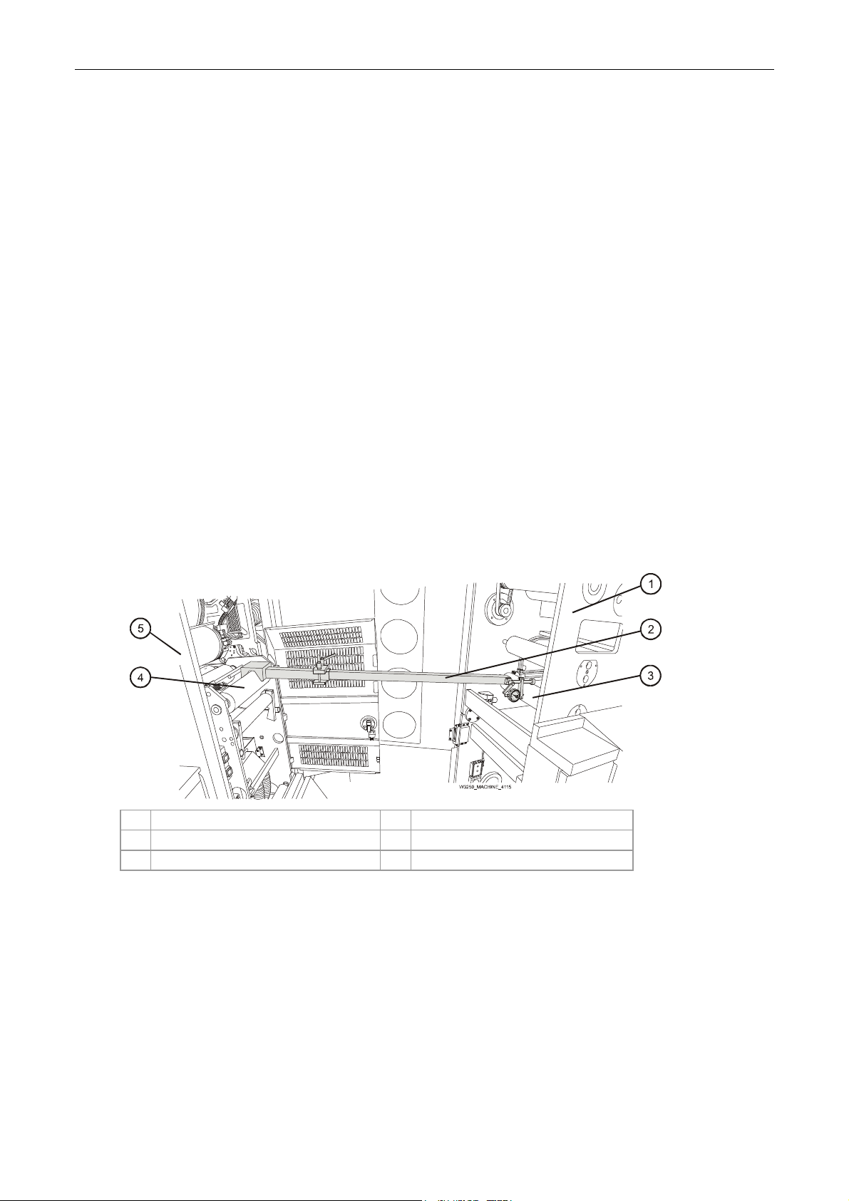
Installation Manual
At the ILP feed
i. While one person places a leveler on the idler No. 3 (Figure 75), and then idler No. 10
(Figure 63), another person should adjust the pull/pu
sh screws at the feed and exit of
the rear lower frame:
i. Turn the push screw counterclockwise to release the internal frame.
ii. Turn the pull screw to adjust the skew of the ILP frame until leveled.
iii. Tighten the push screw to accurately align the ILP.
Repeat until the ILP are sitting firmly on the floor and the ILP is level.
Measure the level to an accuracy of 0.0±0.1 mm.
j. Tighten the six leveling screws until just tight.
Then turn the adjustment nuts one further complete turn and tighten the locking nuts.
At the ILP exit
k. Repeat step g above, placing a leveler on the idler No. 10 (Figure 63), and adjust the
two feet 20 m
m height adjustment nuts until accurately leveled.
Measure the level to an accuracy of 0.0±0.1 mm.
l. Tighten the six leveling screws until just tight and
Then turn the adjustment nuts one further complete turn and tighten the locking nuts.
10. Configure the parallel jig for the long configuration. Refer to the section General information
on pag
Figure 75 Al
e 17.
igning the PE1 and ILP using the Parallel jig
1 ILP 4 PE1 driver roller
2 Parallel jig 4 PE1
3 ILP idler No. 10
At the ILP exit and PE1 feed
11. To align the ILP using the parallel jig:
a. Remove the two screws securing the IR sensor bracket.
Save the screws for later reinstallation.
Carefully place the bracket and sensor aside. Do not disconnect its cable.
CA294-03070 rev 00 page 93 of 153
Page 94

Installation Manual
b. Place the Parallel jig (P/N CA045-07192) between the PE1 drive roller and the ILP
Idler No. 10 (Figure 75).
c.
Move the Parallel jig from front (of press) to rear and back to front (Figure 75).
Make
sure that the difference in distance between PE1 and ILP at both the front and
rear of the press, between the parallel jig readings is 0.00 ±0.01 mm.
Figure 76 Aligning the ILP feed stepping plate rollers
1 Allen M5 rear adjustment screw 6 Allen M5 front adjustment bracket locking
screw
2 Allen M5 rear adjustment bracket locking screw 7 Parallel jig
3 Stepping plate roller (to be aligned) 8 ILP exit stepping plate rollers
4 Gauge bracket 9 PE1
5 Allen M5 front adjustment screw 10 PE1 input idler No. 2
12. To level and align the ILP exit stepping plate rollers (Figure 76):
For each roll
er
a. Place a leveler on the roller and verify that the roller is level at the front and rear.
b. Reconfigure the parallel jig for the intermediate configuration. Refer to the section
General information on page 17.
c.
Place the Parallel jig between the PE1 input idler No. 2 and the roller shown in
Figure 76.
d.
Make sure that the gauge bracket is orientated as shown in Figure 76.
Loosen the Allen M5 front and rear adjustment bracket locking screws.
e. Adjust the Allen M5 front and rear adjustment screws and move the Parallel jig from
front to back to accurately align the roller.
Make sure that the rollers are aligned to an accuracy of 0.00 ± 0.01 mm.
If the difference between the readings is more than 0.00 ± 0.01 mm, turn the
adjustment screw on the front mount of the roller to correct the alignment.
CA294-03070 rev 00 page 94 of 153
Page 95

Installation Manual
e. Tighten the front and rear adjustment bracket locking screws.
Figure 77 Aligning the ILP feed stepping plate rollers - between stepping plate rollers
1 Stepping plate roller (previously aligned and
leveled)
2 Parallel jig (shortened) 6 Allen M5 rear adjustment bracket locking
3 Allen M5 front adjustment screw 7 Allen M5 rear adjustment screw
4 Allen M5 front adjustment bracket locking
screw
5 Stepping plate roller (to be aligned and
leveled)
screw
NOTE: The adjustment screws on the rear mounts of the stepping
plate assembly rollers move the rollers in the up/down
direction. The screws on the front mounts move the rollers in
the web feed direction (Figure 77).
The adjustment screws are locked with setscrews.
f. Reconfigure the parallel jig for the short configuration. Refer to the General
information on page 17.
Use the Paral
lel jig in order to measure the variation in distance between the two
stepping plate rollers as shown in Figure 77.
Mount the Parallel jig between the two rollers.
g. Loosen the Allen M5 front and rear adjustment bracket locking screws (Figure 77).
h.
Adjust the Allen M5 front and rear adjustment screws and move the Parallel jig from
front to back to accurately align the roller (Figure 77).
Make sure that the rollers are aligned to an accuracy of 0.00 ± 0.01 mm.
If the difference between the readings is more than 0.00 ± 0.01 mm, turn the
adjustment screw on the front mount of the roller to correct the alignment.
i. Place a leveler on the roller and verify that the roller is level at the front and rear.
CA294-03070 rev 00 page 95 of 153
Page 96

Installation Manual
j. Tighten the front and rear adjustment bracket locking screws (Figure 77).
13.
14. Rep
15. Rep
Install the ILP feed stepping plate between the Unwinder position and the ILP as described in
step 2 on page 83.
Place the Parallel jig between the unwinder lower roller and the stepping plate rollers.
eat step 4 on page 86 to align the ILP feed stepping plate rollers.
eat step 12 on page 94 to level the ILP feed stepping plate rollers.
CA294-03070 rev 00 page 96 of 153
Page 97

Installation Manual
Installing the ILP web rollers
Figure 78 The priming unit rollers - position in the ILP
1
2
14
13
12
11
10
89
3
4
5
6
7
1 Priming unit 8 Simplex station
2 ILP 9 Duplex station
3 Simplex priming roller 5, SP5 (impression roller) 10 Duplex priming roller 1, SP1 (reservoir roller)
4 Simplex priming roller 4, SP4 (upper rubber
11 Duplex priming roller 2, SP2 (lower rubber roller)
roller)
5 Simplex priming roller 3, SP3 (intermediate
12 Duplex priming roller 3, SP3 (intermediate roller)
roller)
6 Simplex priming roller 2, SP2 (lower rubber
13 Duplex priming roller 4, SP4 (upper rubber roller)
roller)
7 Simplex priming roller 1, SP1 (reservoir roller) 14 Duplex priming roller 5, SP5 (impression roller)
The priming unit consists of two priming stations. Each station consists of five rollers as shown in
Figure 78. Each roller is identified by its number (No. 1 - 5) from th
e lower to top roller. A numbered
outer station roller corresponds to its parallel inner station roller.
CA294-03070 rev 00 page 97 of 153
Page 98

Installation Manual
Figure 79 Identifying the rollers
1 SP1 or DP1 steel roller with ends recessed 4 SP4 or DP4 rubber roller with a narrow priming
surface
2 SP2 or DP2 rubber roller with a wide priming
surface
3 SP3 or DP3 steel roller
5 SP5 or DP5 steel roller
The installation for the inner and outer station rollers is similar. The order of the rollers installation is
as follows (refer to Figure 78 and Figure 63):
1st
2nd Rubber rollers SP2 and DP2
Rubber roller SP4 or DP4
CAUTION: Take care not to damage the priming surface of the
rubber rollers. They are very delicate and can be
damaged easily.
The rubber rollers should be supported by their
shafts either in their shipping box or in the ILP.
They should not be allowed to rest on a flat surface
(even for a short time) as damage will be caused to
the rollers surface.
CA294-03070 rev 00 page 98 of 153
Page 99

Installation Manual
Figure 80 Installing the priming rollers - outer and inner stations
1 Clamp 3 SP2 or DP2 rubber roller
2 Bearing 4 SP4 or DP4 rubber roller
13. To install the priming rollers (Figure 80):
a.
Open the ILP feed door.
b. Remove the outer station priming roller mount clamps.
Place them aside on a flat clean surface.
c. Mount the SP2 rubber, and secure it with the clamps.
d. Mount the SP4 rubber roller, and secure it with the clamps.
e. Open the ILP top cover.
f. Remove the inner station priming roller mount clamps.
Place them aside on a flat clean surface.
g. Mount the DP2 rubber roller, and secure it with the clamps.
h. Mount the DP4 rubber roller, and secure it with the clamps.
CA294-03070 rev 00 page 99 of 153
Page 100

Installation Manual
Installing the unwinder
Positioning the unwinder
1. Place the unwinder on the floor platform at the input side of the ILP.
Figure 81 Moving the unwinder into its final position
1 Unwinder v6 2 Pallet jack
2. Use a pallet jack to move the unwinder into position near the input side of the ILP to a
distance of between 30 - 40 cm from the ILP feed stepping plate assembly.
CAUTION: When moving the unwinder, make sure to place the
pallet jack under the frame as shown in Figure 81.
Otherwise, the unwinder will be damaged.
CA294-03070 rev 00 page 100 of 153
 Loading...