

HP Elite Slice for Meeting Rooms G2 Disassembly Instructions Manual

Product Category: Personal Computers
Marketing Name / Model
[List multiple models if applicabl e.]
HP Elite Slice for Meeting Rooms
1.0 Items Requiring Selective Treatment
Quantity
in product
Printed Circuit Boards (PCB) or Printed Circuit
Assemblies (PCA)
With a surface greater than 10 sq cm
1
Batteries
All types including standard alkaline and lithium
coin or button style batteries
1
Mercury-containing components
For example, mercury in lamps, display backlights,
scanner lamps, switches, batteries
0
Liquid Crystal Displays (LCD) with a surface
greater than 100 sq cm
Includes background illuminated displays with gas
discharge lamps
0
Cathode Ray Tubes (CRT)
0
Capacitors / condensers (Containing PCB/PCT)
0
Electrolytic Capacitors / Condensers measuring
greater than 2.5 cm in diameter or height
0
External electrical cables and cords
0
Gas Discharge Lamps
0
Plastics containing Brominated Flame Retardants
already listed as a separate item above)
0
Components and parts containing toner and ink,
including liquids, semi-liquids (gel/paste) and toner
Include the cartridges, print heads, tubes, vent
chambers, and service stations.
0
Components and waste containing asbestos
0
Product End-of-Life Disassembly Instructions
Purpose: The document is intended for use by end-of-life recyclers or treatment facilities. It provides the basic instructions
for the disassembly of HP products to remove components and materials requiring selective treatment, as defined by EU
directive 2002/96/EC, Waste Electrical and Electronic Equipment (WEEE).
1.1 Items listed below are classified as requiring selective treatment.
1.2 Enter the quantity of items contained within the product which require selective treatment in the right column, as
applicable.
Item Description Notes
weighing > 25 grams (not including PCBs or PCAs
of items
included
EL-MF877-00 Page 1
Template Revision B
PSG instructions for this template are available at EL-MF877-01

Components, parts and materials containing
refractory ceramic fibers
0
Components, parts and materials containing
radioactive substances
0
2.0 Tools Required
List the type and size of the tools that would typically be used to disassemble the product to a point where components
Tool Description
Tool Size (if
applicable)
T15, T8 Electric Screwdriver
Support fixture
M/B B side support fixture
Suction pen
Cross electrical screwdriver
3.0 Product Disassembly Proc ess
and materials requiring selective treatment can be removed.
3.1 List the basic steps that should typically be followed to remove components and materials requiring selective treatment:
1. Follow steps described in Disassembly instruction (file attached)
2. If parts can be removed without using a tool, remove it first
3. Use correct screwdriver and torque value before unlock the screw.
4. Disconnect RTC battery cable and remove battery from M/B.
5. Dispose of all removed components according to regulation requirements.
6.
7.
8.
9.
3.2 Optional Graphic. If the disassembly process is complex, insert a graphic illustration below to identify the items
contained in the product that require selective treatment (with descriptions and arrows identifying locations).
EL-MF877-00 Page 2
Template Revision B
PSG instructions for this template are available at EL-MF877-01
MANUFACTURING PROCESS INSTRUCTIONS
MECHANICAL ASSEMBLY
MODEL : Slice
auditor:
Stanley Chen
Notes : If finding anything uncommon, notice foreman or assistant at once.
Standard Operation Procedure
Document No. : Slice FA Disassembly SOP Station :
Operation name : Ver. : Date :
Holding fixture list (holding fixture standard)
Qty
Holding fixture list (holding fixture standard)
Qty
Step:
Issue Dept.:Auditor:
Stanley Chen
NPSU-PPE
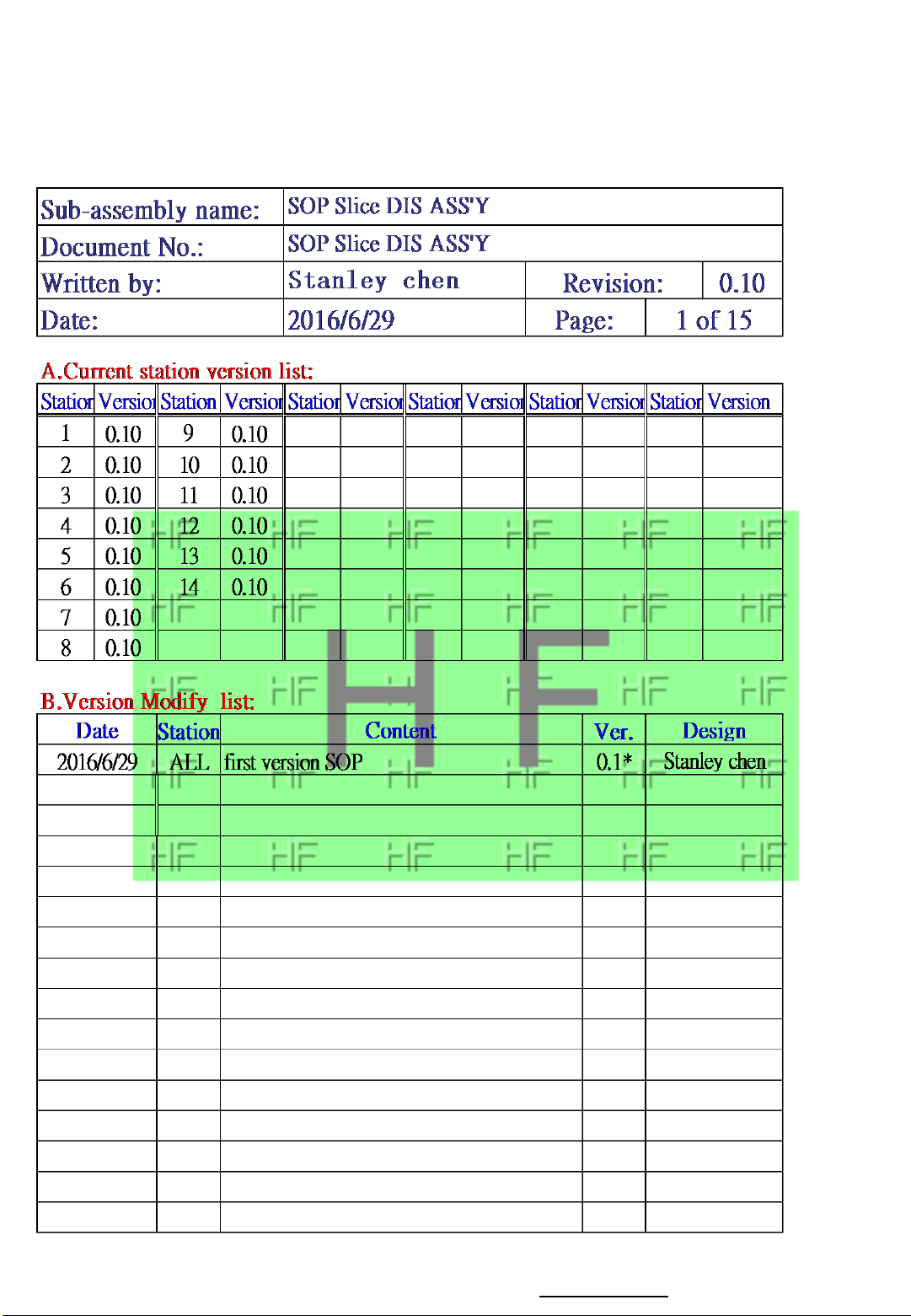
1. Loosen screw *4 of bottom case (Fig.1)
Torque:3.0 ± 0.2 Kgf.cm
2. Take off bottom case (6070B1043901) ,and
put it in the box
Disassembly bottom case
1(1/1)
0.10
2016/6/29
Fig. 1
3
1
2
4
Cross electrical screw driver #1 1
Fig. 2
Notes : If finding anything uncommon, notice foreman or assistant at once.
Standard Operation Procedure
Document No. : Slice FA Disassembly SOP Station :
Operation name : Ver. : Date :
Holding fixture list (holding fixture standard)
Qty
Holding fixture list (holding fixture standard)
Qty
Step:
Issue Dept.:Auditor:
Stanley Chen
NPSU-PPE
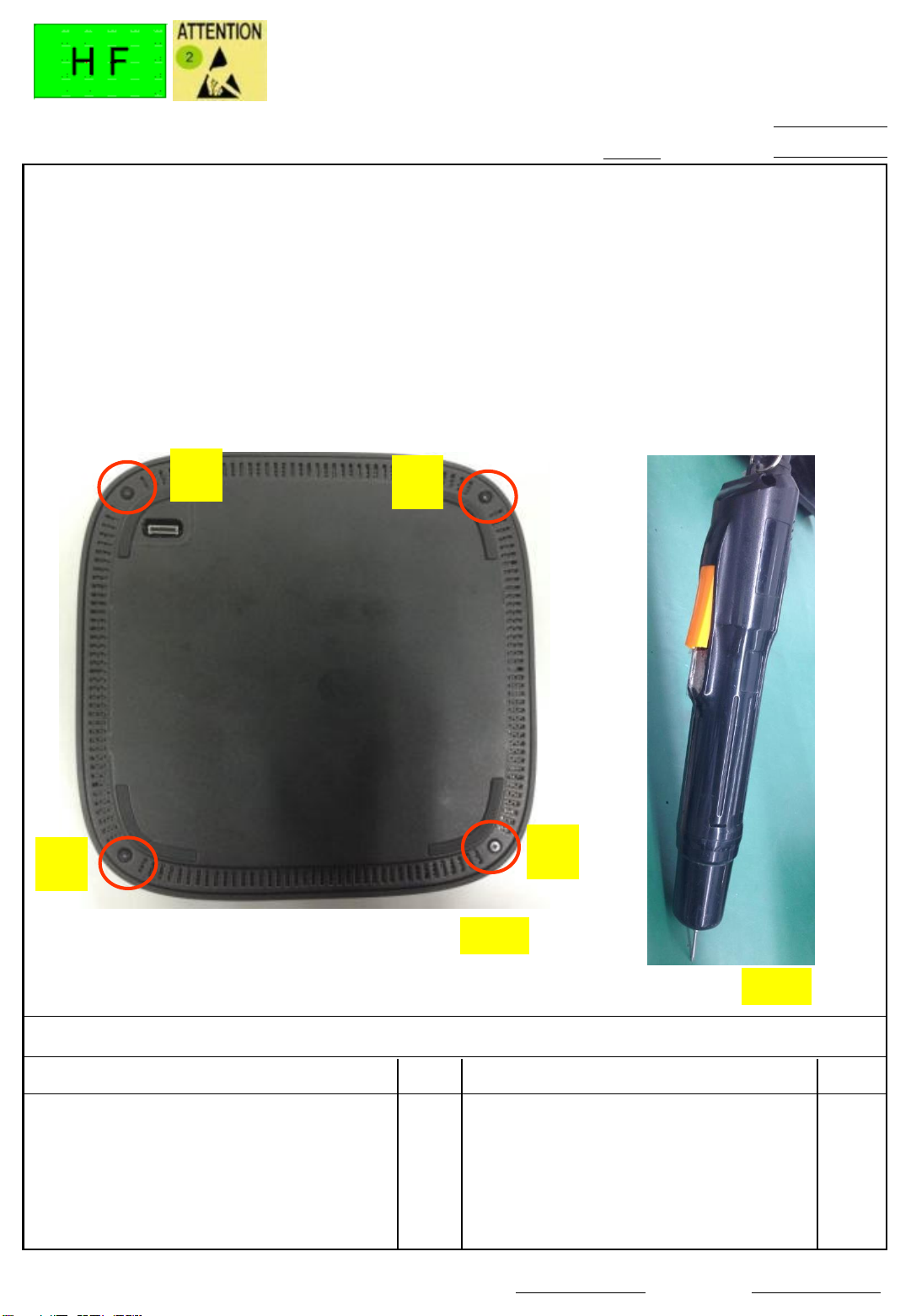
1. Disassembly Speaker connector form MB
2. Disassembly Speaker
module(6039B0082201) and put it in the
box
Do not press the Speaker eardrum when
disassembly the speaker .
Disassembly Speaker
2(1/1)
0.10
2016/6/29
Speaker
Connector
eardrum
Put the right side hook , and
release the speaker .
Notes : If finding anything uncommon, notice foreman or assistant at once.
Standard Operation Procedure
Document No. : Slice FA Disassembly SOP Station :
Operation name : Ver. : Date :
Holding fixture list (holding fixture standard)
Qty
Holding fixture list (holding fixture standard)
Qty
Step:
Issue Dept.:Auditor:
Stanley Chen
NPSU-PPE
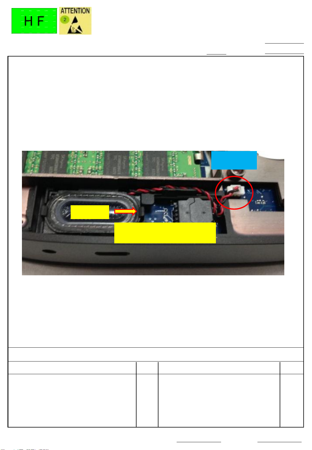
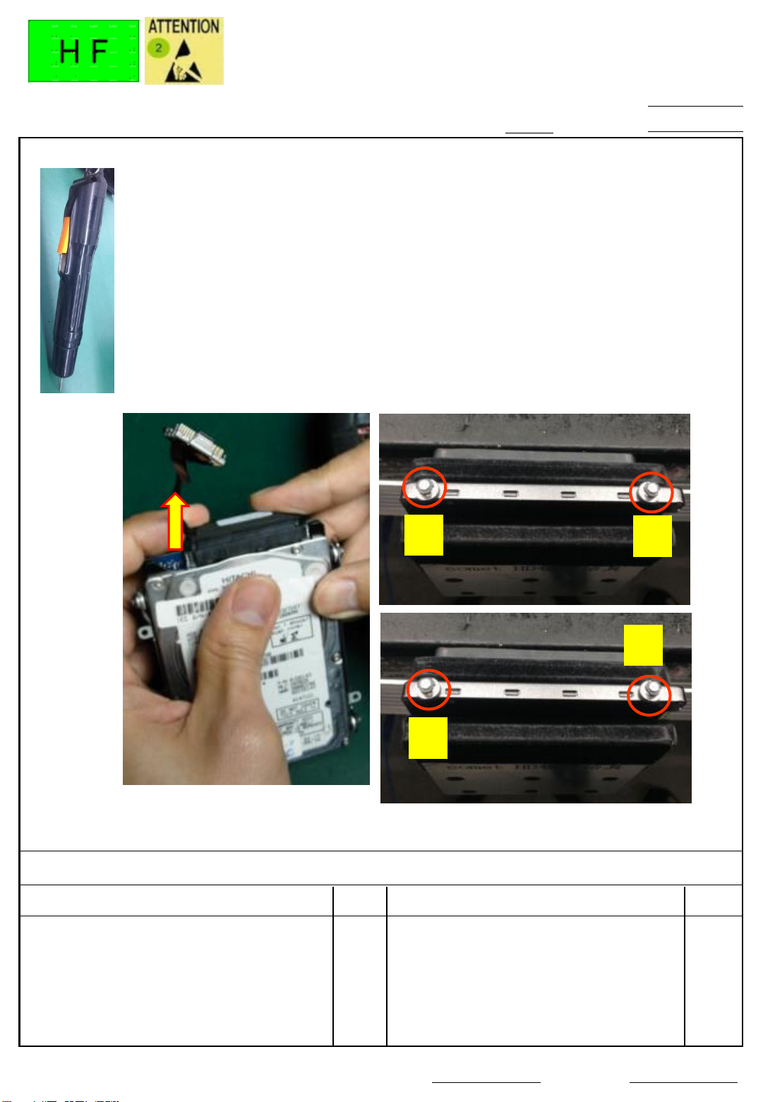
1. Disassembly HDD connector from MB(Fig.
2)
2. Loosen HDD bracket screw *4 (Fig.1)
Torque:2.5 ± 0.2 Kgf.cm
Disassembly HDD
3(1/1)
0.10
2016/6/29
Cross electrical screw driver #1 1
HDD
connector
1
2
3
4
Fig.1
Fig.2
Fig.3
Notes : If finding anything uncommon, notice foreman or assistant at once.
Standard Operation Procedure
Document No. : Slice FA Disassembly SOP Station :
Operation name : Ver. : Date :
Holding fixture list (holding fixture standard)
Qty
Holding fixture list (holding fixture standard)
Qty
Step:
Issue Dept.:Auditor:
Stanley Chen
NPSU-PPE
1. Take HDD and remove the HDD cable
from the HDD . Put it in the box . (fig.1)
2. Loosen HDD bracket screw
(6054B1636401)*4 from the both side of
the HDD . (Fig.2)
Torque:2.5 ± 0.2 Kgf.cm
3. Put the HDD bracket and HDD in the
different box .
Disassembly HDD
4(1/1)
0.10
2016/6/29
1
3
4
2
Fig. 2
Fig.1
Cross electrical screw driver #1 1
HDD support fixture 1
Fig.3
Notes : If finding anything uncommon, notice foreman or assistant at once.
Standard Operation Procedure
Document No. : Slice FA Disassembly SOP Station :
Operation name : Ver. : Date :
Holding fixture list (holding fixture standard)
Qty
Holding fixture list (holding fixture standard)
Qty
Step:
Issue Dept.:Auditor:
Stanley Chen
NPSU-PPE
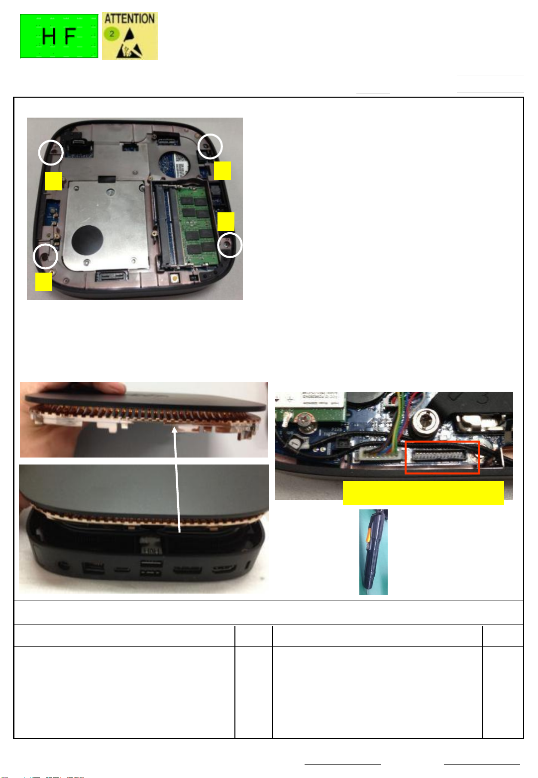
1. Loosen screw *4 of the middle frame (Fig.
1)
Torque:3.0 ± 0.2 Kgf.cm
2. Turn over the machine , and disassembly
top case . (Fig.2)
3. Only for Touch model
Disassembly cable (6017B0773101)
connector on touch/B , and disassembly
the other side connector on M/B . Put the
cable in the box . (Fig.3)
4. Only for charger model
Disassembly cable connector on touch/B ,
and disassembly the other side connector
on M/B . Put the cable in the box . (Fig.3)
Disassembly top cover
5(1/1)
0.10
2016/6/29
Cross electrical screw driver #1 1
4
1
3
2
Fig.2
Fig. 1
Touch ,charger CNTR
Fig. 3
Fig.4
Notes : If finding anything uncommon, notice foreman or assistant at once.
Standard Operation Procedure
Document No. : Slice FA Disassembly SOP Station :
Operation name : Ver. : Date :
Holding fixture list (holding fixture standard)
Qty
Holding fixture list (holding fixture standard)
Qty
Step:
Issue Dept.:Auditor:
Stanley Chen
NPSU-PPE
1
4
3
2
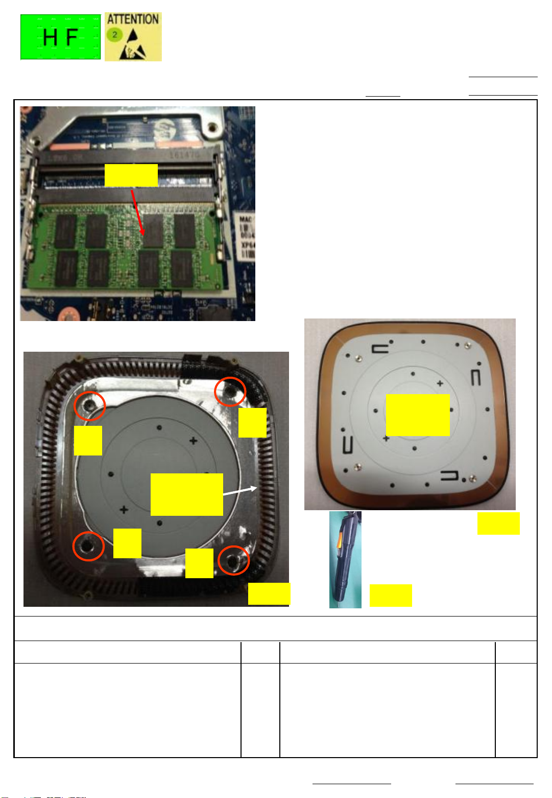
Thermal
cover
1. Disassembly DDR from the M/B , and put
it in the box .(Fig.1)
The numbers of DDR disassembly is base
on it on the M/B .
2. Loosen thermal cover
screw(6052B0156301) *4 (Fig.2)
Torque:2.0 ± 0.2 Kgf.cm
3 . Put top cover & thermal cover
(6070B1042401) in the different box.
Disassembly DDR & thermal cover
6(1/1)
0.10
2016/6/29
Cross electrical screw driver #1 1
Fig.2
Top
cover
Fig.3
Fig.1
DDR
Fig.4
 Loading...