

HP EliteBook x360 830 G5 Maintenance And Service Manual

Maintenance and Service Guide
HP EliteBook x360 830 G5 Notebook PC
IMPORTANT! This document is intended for HP authorized service
providers only.

© Copyright 2019 HP Development Company,
L.P.
Bluetooth is a trademark owned by its
proprietor and used by HP Inc. under license.
Intel and Core are trademarks of Intel
Corporation or its subsidiaries in the U.S.
and/or other countries. Windows is either a
registered trademark or trademark of
Microsoft Corporation in the United States
and/or other countries.
The information contained herein is subject to
change without notice. The only warranties for
HP products and services are set forth in the
express warranty statements accompanying
such products and services. Nothing herein
should be construed as constituting an
additional warranty. HP shall not be liable for
technical or editorial errors or omissions
contained herein.
First Edition: April 2019
Document Part Number: L56008-001
Product notice
This guide describes features that are common
to most models. Some features may not be
available on your computer.
Not all features are available in all editions or
versions of Windows. Systems may require
upgraded and/or separately purchased
hardware, drivers, software or BIOS update to
take full advantage of Windows functionality.
Windows 10 is automatically updated, which is
always enabled. ISP fees may apply and
additional requirements may apply over time
for updates. Go to http://www.microsoft.com
for details.
To access the latest user guides, go to
http://www.hp.com/support, and follow the
instructions to nd your product. Then select
User Guides.
Software terms
By installing, copying, downloading, or
otherwise using any software product
preinstalled on this computer, you agree to be
bound by the terms of the HP End User License
Agreement (EULA). If you do not accept these
license terms, your sole remedy is to return the
entire unused product (hardware and software)
within 14 days for a full refund subject to the
refund policy of your seller.
For any further information or to request a full
refund of the price of the computer, please
contact your seller.

Important Notice about Customer Self-Repair Parts
CAUTION: Your computer includes Customer Self-Repair parts and parts that should only be accessed by an
authorized service provider. See Chapter 5, "Removal and replacement procedures for Customer Self-Repair
parts," for details. Accessing parts described in Chapter 6, "Removal and replacement procedures for
Authorized Service Provider only parts," can damage the computer or void your warranty.
iii

iv Important Notice about Customer Self-Repair Parts

Safety warning notice
CAUTION: To reduce the possibility of heat-related injuries or of overheating the device, do not place the
device directly on your lap or obstruct the device air vents. Use the device only on a hard, at surface. Do not
allow another hard surface, such as an adjoining optional printer, or a soft surface, such as pillows or rugs or
clothing, to block airow. Also, do not allow the AC adapter to contact the skin or a soft surface, such as
pillows or rugs or clothing, during operation. The device and the AC adapter comply with the user-accessible
surface temperature limits dened by applicable safety standards.
v

vi Safety warning notice

Table of contents
1 Product description ....................................................................................................................................... 1
2 Components .................................................................................................................................................. 6
Right ....................................................................................................................................................................... 6
Left ......................................................................................................................................................................... 8
Display .................................................................................................................................................................... 9
Keyboard area ...................................................................................................................................................... 10
TouchPad ........................................................................................................................................... 10
Lights ................................................................................................................................................. 11
Speakers and ngerprint sensor ....................................................................................................... 12
Special keys ....................................................................................................................................... 13
Hot keys (select products only) ......................................................................................................... 14
Bottom ................................................................................................................................................................. 14
Top ........................................................................................................................................................................ 15
Labels ................................................................................................................................................................... 16
Inserting a SIM card (select products only) ......................................................................................................... 17
3 Illustrated parts catalog .............................................................................................................................. 18
Computer major components .............................................................................................................................. 18
Mass storage devices ........................................................................................................................................... 21
Miscellaneous parts ............................................................................................................................................. 21
Cable Kit ............................................................................................................................................................... 22
Plastics Kit ........................................................................................................................................................... 23
Bracket Kit ............................................................................................................................................................ 24
4 Removal and replacement procedures preliminary requirements .................................................................... 25
Tools required ...................................................................................................................................................... 25
Service considerations ......................................................................................................................................... 25
Plastic parts ....................................................................................................................................... 25
Cables and connectors ...................................................................................................................... 25
Drive handling ................................................................................................................................... 26
Workstation guidelines ..................................................................................................................... 26
Electrostatic discharge information .................................................................................................................... 26
Generating static electricity .............................................................................................................. 27
Preventing electrostatic damage to equipment ............................................................................... 27
Personal grounding methods and equipment .................................................................................. 28
vii

Grounding the work area ................................................................................................................... 28
Recommended materials and equipment ........................................................................................ 28
Packaging and transporting guidelines .............................................................................................................. 29
5 Removal and replacement procedures for Customer Self-Repair parts ............................................................. 30
Component replacement procedures .................................................................................................................. 30
Preparation for disassembly ............................................................................................................. 30
Bottom cover ..................................................................................................................................... 31
Battery ............................................................................................................................................... 33
WLAN module .................................................................................................................................... 34
WWAN module ................................................................................................................................... 36
Solid-state drive ................................................................................................................................ 38
Memory module ................................................................................................................................ 40
6 Removal and replacement procedures for authorized service provider parts .................................................... 42
Component replacement procedures .................................................................................................................. 42
Preparation for disassembly ............................................................................................................. 42
Display assembly ............................................................................................................................... 43
RTC battery ........................................................................................................................................ 45
NFC module ....................................................................................................................................... 46
TouchPad ........................................................................................................................................... 47
Card reader board .............................................................................................................................. 48
NFC interface board (models without a card reader) ........................................................................ 49
Fan ..................................................................................................................................................... 50
Heat sink ............................................................................................................................................ 51
System board .................................................................................................................................... 53
Speakers ............................................................................................................................................ 57
Fingerprint sensor board .................................................................................................................. 58
Power button board .......................................................................................................................... 59
Top cover with keyboard ................................................................................................................... 60
7 Computer Setup (BIOS), TPM, and HP Sure Start ............................................................................................. 61
Using Computer Setup ......................................................................................................................................... 61
Starting Computer Setup .................................................................................................................. 61
Navigating and selecting in Computer Setup ................................................................................... 61
Restoring factory settings in Computer Setup ................................................................................. 61
Updating the BIOS ............................................................................................................................. 62
Determining the BIOS version ......................................................................................... 62
Downloading a BIOS update ........................................................................................... 62
Changing the boot order using the f9 prompt .................................................................................. 63
viii

TPM BIOS settings (select products only) ........................................................................................................... 63
Using HP Sure Start (select products only) ......................................................................................................... 64
8 Using HP PC Hardware Diagnostics ................................................................................................................ 65
Using HP PC Hardware Diagnostics Windows (select products only) ................................................................. 65
Downloading HP PC Hardware Diagnostics Windows ....................................................................... 65
Downloading the latest HP PC Hardware Diagnostics Windows version ....................... 66
Downloading HP Hardware Diagnostics Windows by product name or number
(select products only)
Installing HP PC Hardware Diagnostics Windows ............................................................................. 66
Using HP PC Hardware Diagnostics UEFI ............................................................................................................. 66
Starting HP PC Hardware Diagnostics UEFI ....................................................................................... 67
Downloading HP PC Hardware Diagnostics UEFI to a USB ash drive .............................................. 67
Downloading the latest HP PC Hardware Diagnostics UEFI version .............................. 67
Downloading HP PC Hardware Diagnostics UEFI by product name or number
(select products only) ..................................................................................................... 67
Using Remote HP PC Hardware Diagnostics UEFI settings (select products only) ............................................. 68
Downloading Remote HP PC Hardware Diagnostics UEFI ................................................................. 68
Downloading the latest Remote HP PC Hardware Diagnostics UEFI version ................. 68
Downloading Remote HP PC Hardware Diagnostics UEFI by product name or
number ............................................................................................................................ 68
Customizing Remote HP PC Hardware Diagnostics UEFI settings .................................................... 68
..................................................................................................... 66
9 Backing up, restoring, and recovering ........................................................................................................... 70
Backing up information and creating recovery media ........................................................................................ 70
Using Windows tools ......................................................................................................................... 70
Using the HP Cloud Recovery Download Tool to create recovery media (select products only) ..... 70
Restoring and recovery ........................................................................................................................................ 71
Restoring, resetting, and refreshing using Windows tools .............................................................. 71
Recovering using HP Recovery media ............................................................................................... 71
Changing the computer boot order ................................................................................................... 71
10 Specications ............................................................................................................................................ 72
11 Power cord set requirements ...................................................................................................................... 73
Requirements for all countries ............................................................................................................................ 73
Requirements for specic countries and regions ................................................................................................ 74
12 Statement of memory volatility .................................................................................................................. 76
Nonvolatile memory usage ................................................................................................................................. 78
ix

Questions and answers ....................................................................................................................................... 80
Using HP Sure Start (select models only) ............................................................................................................ 81
13 Recycling .................................................................................................................................................. 82
Index ............................................................................................................................................................. 83
x

1 Product description
Table 1-1 Product components and their descriptions
Category Description
Product Name HP EliteBook x360 830 G5 Notebook PC
Processor 8th Generation Intel® Core™ processors
Intel Core i7-8650U (1.9 GHz, turbo up to 4.2 GHz, 8 MB SmartCache, quad core, 15 W)
Intel Core i7-8550U (1.8 GHz, turbo up to 4.0 GHz, 8 MB SmartCache, quad core, 15 W)
Intel Core i5-8350U (1.7 GHz, turbo up to 3.6 GHz, 6 MB SmartCache, quad core, 15 W)
Intel Core i5-8250U (1.6 GHz, turbo up to 3.4 GHz, 6 MB SmartCache, quad core, 15 W)
Intel Core i3-8130U (2.2 GHz, turbo up to 3.4 GHz, 4 MB SmartCache, quad core, 15 W)
Graphics Integrated UMA graphics
Intel UHD Graphics 620
Supports HD decode, DX12, HDMI 1.4, and HDCP 2.2 via DisplayPort up to 4K @ 60 Hz and via HDMI up to 4K
@ 30 Hz
Supports 2 external monitors when on the HP Elite 90W Thunderbolt 3 Dock; Max resolution = 2.5K @ 60 Hz
(DisplayPort 1) and 2.5K @ 60 Hz (DisplayPort 2) or 4K @ 60 Hz (one DisplayPort) and 4K @ 60 Hz (Type-C
output port using a Type C-to-DP adapter)
Supports 2 external monitors when on the HP Thunderbolt Dock 120W G2; Max resolution = 2.5K @ 60 Hz
(DisplayPort 1) and 2.5K @ 60 Hz (DisplayPort 2) or 4K @ 60 Hz (one DisplayPort) and 4K @ 60 Hz (Type-C
output port using a Type C-to-DP adapter)
Display panel 33.8-cm (13.3 in.), FHD (1920 × 1080), UWVA, touch screen, narrow bezel
Anti glare, 1000 nits, 72% CG, eDP + PSR, ultra slim, ambient light sensor, HD + IR camera, for WWAN
BrightView, 1000 nits, 72% CG, eDP + PSR, ultra slim, ambient light sensor, HD + IR camera, for WWAN
BrightView, 1000 nits, 72% CG, eDP + PSR, ultra slim, ambient light sensor, HD + IR camera
Anti glare, 400 nits, 72% CG, eDP + PSR, ultra slim, ambient light sensor, HD + IR camera, for WWAN
BrightView, 400 nits, 72% CG, eDP + PSR, ultra slim, ambient light sensor, HD + IR camera, for WWAN
BrightView, 400 nits, 72% CG, eDP + PSR, ultra slim, ambient light sensor, HD + IR camera
BrightView, 250 nits, 45% CG, eDP, slim, HD camera, for WWAN
BrightView, 250 nits, 45% CG, eDP, slim, HD camera
BrightView, 220 nits, 45% CG, eDP, slim, HD camera, for WWAN
BrightView, 220 nits, 45% CG, eDP, slim, HD camera
Memory Two SODIMM slots, accessible/upgradeable
DDR4-2400 dual channel support (quad core processors)
DDR4-2133 dual channel support (dual core processors)
Supports up to 32 GB maximum system memory in the following congurations:
1

Table 1-1 Product components and their descriptions (continued)
Category Description
● 32 GB (16 GB × 2)
● 24 GB (16 GB + 8 GB)
● 20 GB (16 GB + 4 GB)
● 16 GB (16 GB × 1 or 8 GB × 2)
● 12 GB (8 GB + 4 GB)
● 8 GB (8 GB × 1 or 4 GB × 2)
● 4 GB (4 GB × 1)
Operating system
recovery storage
Storage M.2 2280 solid-state drive (NGFF)
Audio HP Bang and Olufsen Audio
Video Camera, HD RGB 720p
32 GB eMMC
2 TB, PCIe, Gen 3 × 4, NVMe, SS, TLC
1 TB, PCIe, Gen 3 × 4, NVMe, SS, TLC
512 GB, PCIe, Gen 3 × 4, NVMe, SS, TLC (Opal 2)
512 GB, PCIe, Gen 3 × 4, NVMe, SS, TLC
512 GB, SATA-3, SS, TLC (FIPS 140-2)
256 GB, PCIe, Gen 3 × 4, NVMe, SS, TLC
256 GB, PCIe, NVMe, SS, value
256 GB, SATA-3, SS, TLC (FIPS 140-2)
128 GB, SATA-3, SS, TLC
Multi array including world-facing third microphone
Dual speakers
Camera, HD RGB 720p + IR
Wireless networking WLAN options with dual antennas (M.2 2230 socket PCIe/USB) (select products only)
2 Chapter 1 Product description
Supports Wide Dynamic Range (WDR)
● Intel Dual Band Wireless-AC 8265 802.11ac 2 × 2 Wi-Fi + Bluetooth 4.2 (vPro)
● Intel Dual Band Wireless-AC 8265 802.11ac 2 × 2 Wi-Fi + Bluetooth 4.2 (non-vPro)
WLAN antennas (2) congured at top of display panel
Support for HP LAN-Wireless Protection (WLAN/LAN/WWAN switching)
Support for HP Connection Optimizer
Support for Miracast-certied devices
Support for S3/S4 wake on Wireless LAN
Support for Dynamic BIOS SAR

Table 1-1 Product components and their descriptions (continued)
Category Description
Support for Turbo Lite Wi-Fi
Near-Field Communication (NFC) (select products only)
NXP NPC300 Near Field Communication Module
NFC antenna congured on computer
WWAN options with dual antennas (select products only)
● Integrated WWAN options (M.2 30 × 42 socket USB2): Intel XMM™ 7262 LTE-Advanced (CAT 6)
● Integrated WWAN options (M.2 30 × 42 socket PCIe): Intel XMM 7360 LTE-Advanced (CAT 9)
● Integrated WWAN options (M.2 30 × 42 socket PCIe): Intel XMM 7560 LTE-Advanced Pro (CAT 16)
SIM (4FF/nano SIM) user accessible on side of unit
WWAN modules compatible with programmable removable eSIM
WWAN antennas (2) (world wide 5 band, congured at top of display panel on WWAN models)
Supports WWAN after market option
Ports (2) USB Type-C ports (Thunderbolt)
(2) USB 3.1 Gen 1 Type A ports, 1 charging
Headphone/microphone combo jack
High-denition multimedia interface (HDMI) v 1.4b
External Nano (4FF) SIM slot for WWAN
Keyboard/pointing
devices
Power requirements Battery
Keyboard
HP Collaboration Keyboard
Backlit, spill-resistant with drain, HP Dura Keys
Backlit, spill-resistant with drain, HP Dura Keys, privacy
TouchPad requirements
Glass TouchPad
Microsoft Precision Touchpad Default Gestures support
Firmware PTP with lter driver
No hybrid mode support
4-cell, 53 Whr, HP Long Life lithium polymer soft-pack battery
HP Fast Charge Technology (50% in 30 minutes with 65 W AC adapter)
AC adapter
65 W HP Smart AC adapter, 4.5 mm, right angle
65 W HP Smart AC adapter, 4.5 mm, right angle – Argentina
65 W HP Smart AC adapter, 4.5 mm, right angle – EM
3

Table 1-1 Product components and their descriptions (continued)
Category Description
65 W HP Smart AC adapter, USB Type-C, straight
45 W HP Smart AC adapter, 4.5 mm, right angle
45 W HP Smart AC adapter, 4.5 mm, right angle – Argentina
45 W HP Smart AC adapter, 4.5 mm, right angle – 2-prong (Japan only)
45 W HP Smart AC adapter, USB Type-C, straight
Power cord
3-wire plug,1.0 m, conventional power cord (C5)
3-wire plug,1.8 m, conventional power cord (C5)
2-wire plug,1.0 m, conventional power cord (C7)
Duckhead power cord (C5NS), 1.0 m
Duckhead power cord (C5NS), 1.8 m
Duckhead adapter (C5NS)
Security Trusted Platform Module (TPM) 2.0, Inneon, soldered down
Fingerprint sensor (select products only)
Security lock
Touch ngerprint sensor (landed, touch with 8 × 8 sensor) (select products only)
Preboot Authentication (password, smart card)
Smart Card Reader (active) (select products only)
Hardware-enforced rmware protection: HP Hardware Root of Trust + Sure Start Gen 4
Operating system Operating system version
Windows® 10 RS5
Preinstalled
Windows 10 Home 64
Windows 10 Home 64 Advanced
Windows 10 Home 64 Advanced Single Language
Windows 10 Home 64 Chinese Market CPPP
Windows 10 Home 64 High-end Chinese Market CPPP
Windows 10 Home 64 Plus
Windows 10 Home 64 Plus Single Language
Windows 10 Home 64 Plus Single Language APAC EM PPP
4 Chapter 1 Product description
Windows 10 Home 64 Plus Single Language India Market PPP
Windows 10 Home 64 Plus Single Language Indonesia Market PPP
Windows 10 Home 64 Single Language

Table 1-1 Product components and their descriptions (continued)
Category Description
Windows 10 Home 64 Single Language APAC EM PPP
Windows 10 Home 64 Single Language India Market PPP
Windows 10 Home 64 Single Language Indonesia Market PPP
Windows 10 Home 64 StF MSNA for Higher Education Strategic
Windows 10 Pro 64
Windows 10 Pro 64 Chinese Market
Windows 10 Pro 64 StF MSNA Plus
Windows 10 Pro 64 StF MSNA Standard
Windows 10 Pro 64 StF MSNA Strategic
FreeDOS 3.0
Restore media
Windows 10 Driver DVD
Windows 10 Driver USB
Windows 10 Professional 64-bit Operating System DVD
Windows 10 Professional 64-bit Operating System USB
Certied
Microsoft WHQL
Web-only support
Windows 10 Enterprise 64
Windows 10 Pro 64 CBB 1803
Serviceability End-user replaceable part
AC adapter
5
2 Components
Your computer features top-rated components. This chapter provides details about your components, where
they are located, and how they work.
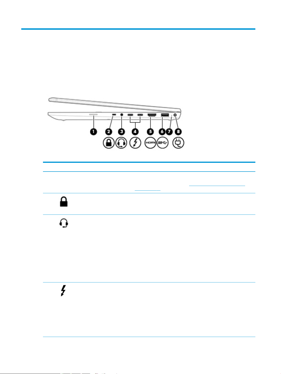
Right
Table 2-1 Right-side components and their descriptions
Component Description
(1) SIM card slot (select products only) Supports a wireless subscriber identity module (SIM) card.
For SIM card installation steps, see Inserting a SIM card (select products
only) on page 17.
(2) Security cable slot Attaches an optional security cable to the computer.
NOTE: The security cable is designed to act as a deterrent, but it may not
prevent the computer from being mishandled or stolen.
(3) Audio-out (headphone)/Audio-in
(microphone) combo jack
(4) USB Type-C Thunderbolt ports
with HP Sleep and Charge (2)
Connects optional powered stereo speakers, headphones, earbuds, a
headset, or a television audio cable. Also connects an optional headset
microphone. This jack does not support optional standalone microphones.
WARNING! To reduce the risk of personal injury, adjust the volume before
putting on headphones, earbuds, or a headset. For additional safety
information, refer to the Regulatory, Safety, and Environmental Notices.
To access this guide:
▲ Select the Start button, select HP Help and Support, and then select
HP Documentation.
NOTE: When a device is connected to the jack, the computer speakers are
disabled.
Even when the computer is o, connect and charge most USB devices that
have a Type-C connector, such as a cell phone, camera, activity tracker, or
smartwatch, and provide high-speed data transfer.
– and –
Connect a display device that has a USB Type-C connector, providing
DisplayPort output.
NOTE: Your computer may also support a Thunderbolt docking station.
NOTE: Cables and/or adapters (purchased separately) may be required.
6 Chapter 2 Components

Table 2-1 Right-side components and their descriptions (continued)
Component Description
(5) HDMI port Connects an optional video or audio device, such as a high-denition
(6) USB SuperSpeed port Connects a USB device, such as a cell phone, camera, activity tracker, or
(7) Battery light When AC power is connected:
(8) Power connector Connects an AC adapter.
television, any compatible digital or audio component, or a high-speed High
Denition Multimedia Interface (HDMI) device.
smartwatch, and provides high-speed data transfer.
● White: The battery charge is greater than 90 percent.
● Amber: The battery charge is from 0 to 90 percent.
● O: The battery is not charging.
When AC power is disconnected (battery not charging):
● Blinking amber: The battery has reached a low battery level. When the
battery has reached a critical battery level, the battery light begins
blinking rapidly.
● O: The battery is not charging.
Right 7
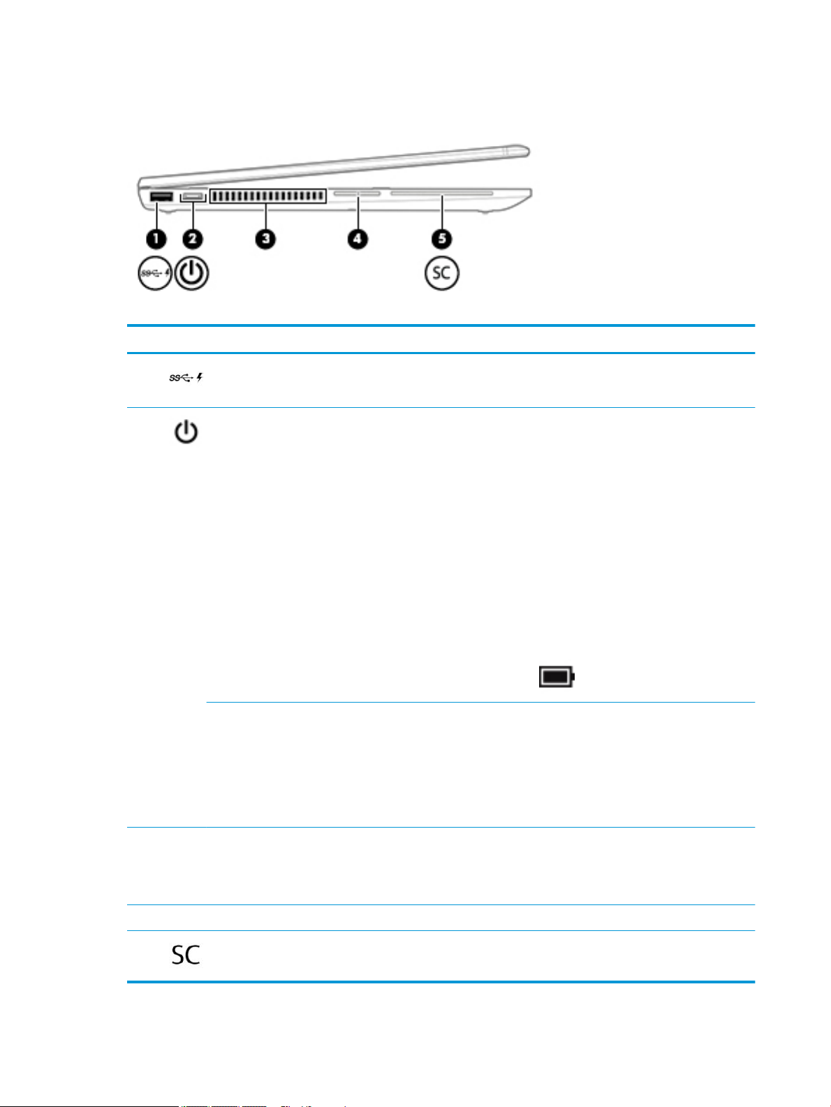
Left
Table 2-2 Left-side components and their descriptions
Component Description
(1) USB SuperSpeed port with HP
Sleep and Charge
(2) Power button and power light Power button:
Power light:
Connects a USB device, provides high-speed data transfer, and even when the
computer is o, charges most products such as a cell phone, camera, activity
tracker, or smartwatch.
● When the computer is o, press the button to turn on the computer.
● When the computer is on, press the button briey to initiate Sleep.
● When the computer is in the Sleep state, press the button briey to exit Sleep
(select products only).
● When the computer is in Hibernation, press the button briey to exit
Hibernation.
CAUTION: Pressing and holding down the power button results in the loss of
unsaved information.
If the computer has stopped responding and shutdown procedures are ineective,
press and hold the power button for at least 5 seconds to turn o the computer.
To learn more about your power settings, see your power options.
▲ Right-click the Power meter icon and then select Power Options.
● On: The computer is on.
● Blinking: The computer is in the Sleep state, a power-saving state. The
computer shuts o power to the display and other unneeded components.
● O: The computer is o or in Hibernation. Hibernation is a power-saving state
that uses the least amount of power.
(3) Vent Enables airow to cool internal components.
(4) Volume button Controls speaker volume on the computer.
(5) Smart card reader Supports optional smart cards.
8 Chapter 2 Components
NOTE: The computer fan starts up automatically to cool internal components and
prevent overheating. It is normal for the internal fan to cycle on and o during
routine operation.
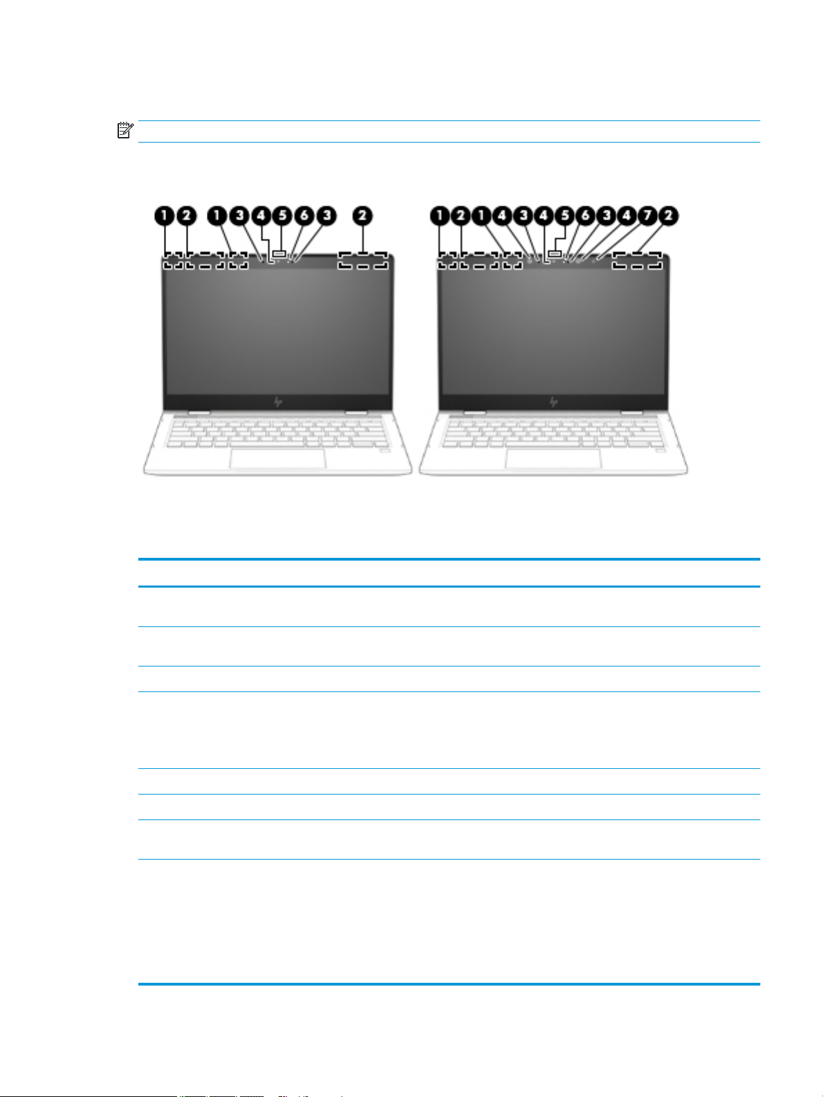
Display
NOTE: Refer to the illustration that most closely matches your computer.
Table 2-3 Display components and their descriptions
Component Description
(1) WLAN antennas* (select products only) Send and receive wireless signals to communicate with wireless local area
networks (WLANs).
(2) WWAN antennas* (select products only) Send and receive wireless signals to communicate with wireless wide area
networks (WWANs).
(3) Internal microphones Record sound.
(4) Camera(s) Allow(s) you to video chat, record video, and record still images. Some cameras
also allow a facial recognition logon to Windows, instead of a password logon.
NOTE: Camera functions vary depending on the camera hardware and
software installed on your product.
(5) Camera privacy switch Turns the camera o and on.
(6) Camera light(s) On: One or more cameras are in use.
(7) Ambient light sensor (select products
only)
*The antennas are not visible from the outside of the computer. For optimal transmission, keep the areas immediately around the
antennas free from obstructions.
For wireless regulatory notices, see the section of the Regulatory, Safety, and Environmental Notices that applies to your country or
region.
To access this guide:
▲ Select the Start button, select HP Help and Support, and then select HP Documentation.
Adjusts the brightness of the display, depending on the ambient light.
Display 9
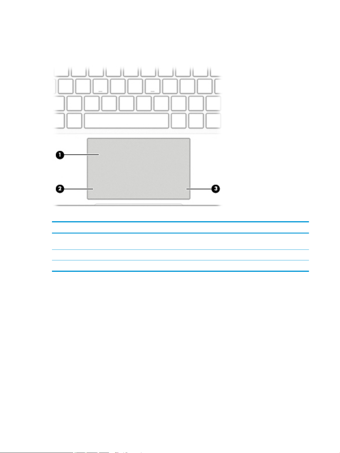
Keyboard area
TouchPad
Table 2-4 TouchPad components and their descriptions
Component Description
(1) TouchPad zone Reads your nger gestures to move the pointer or activate
items on the screen.
(2) Left TouchPad button Functions like the left button on an external mouse.
(3) Right TouchPad button Functions like the right button on an external mouse.
10 Chapter 2 Components
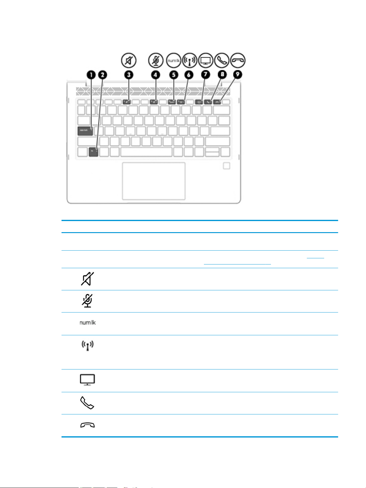
Lights
Table 2-5 Lights and their descriptions
Component Description
(1) Caps lock light On: Caps lock is on, which switches the key input to all capital
letters.
(2) Fn lock light On: The fn key is locked. For more information, see Hot keys
(select products only) on page 14.
(3) Mute light ● On: Computer sound is o.
● O: Computer sound is on.
(4) Microphone mute light ● On: Microphone is o.
● O: Microphone is on.
(5) Num lk light On: Num lock is on.
(6) Wireless light On: An integrated wireless device, such as a wireless local area
network (WLAN) device and/or a Bluetooth® device, is on.
NOTE: On some models, the wireless light is amber when all
wireless devices are o.
(7) Sharing or presenting light On: Sharing is on.
(8) Call answer light On: Call answer is on.
(9) Call end light On: Call end is on.
Keyboard area 11
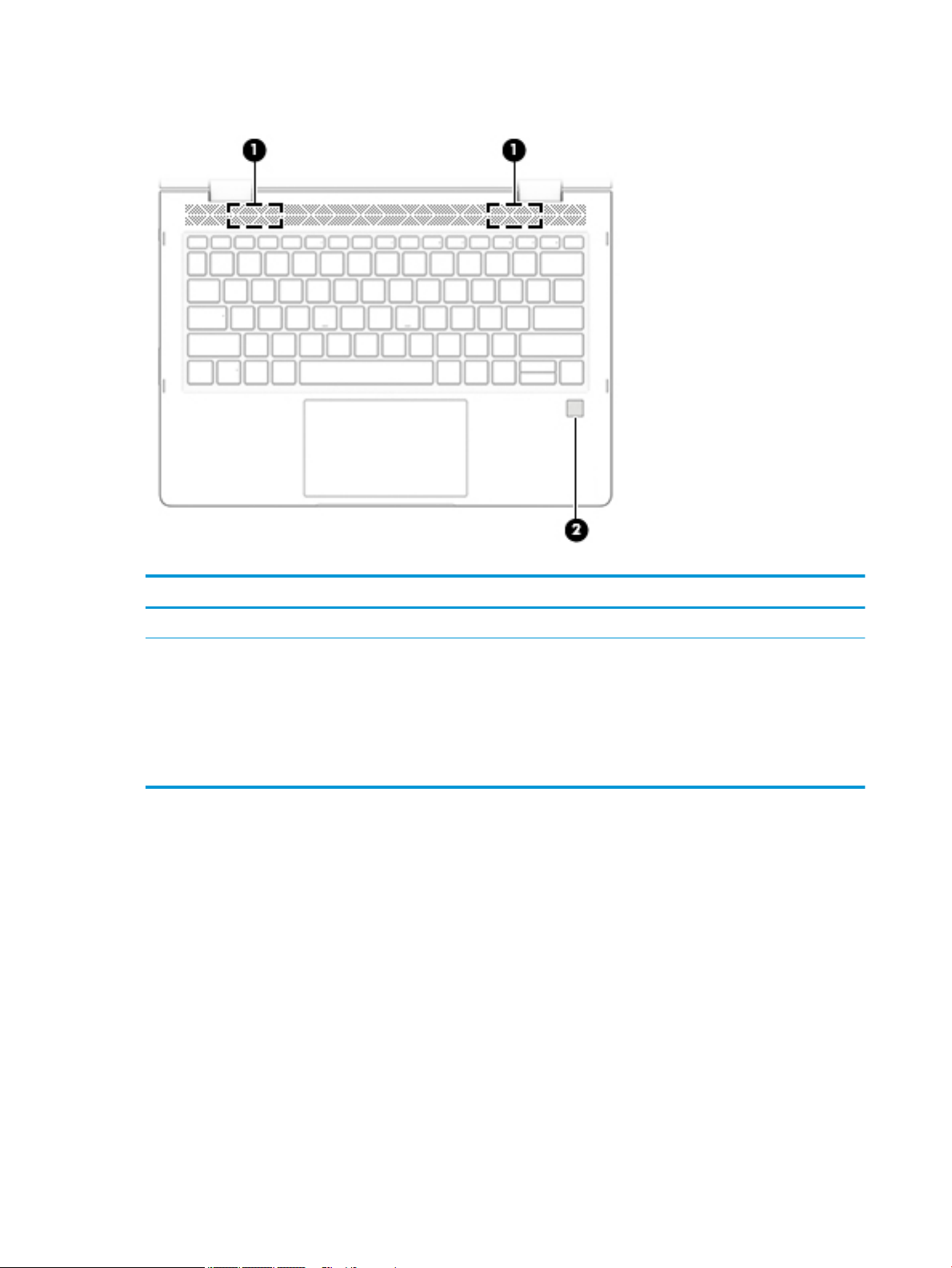
Speakers and ngerprint sensor
Table 2-6 Speakers and ngerprint sensor and their descriptions
Component Description
(1) Speakers Produce sound.
(2) Fingerprint sensor (select products only) Allows a ngerprint logon to Windows, instead of a password
logon.
▲ To use the ngerprint sensor, place your nger on the
ngerprint sensor until it reads your ngerprint.
IMPORTANT: To prevent ngerprint logon issues, make
sure when you register your ngerprint that all sides of your
nger are registered by the ngerprint sensor.
12 Chapter 2 Components
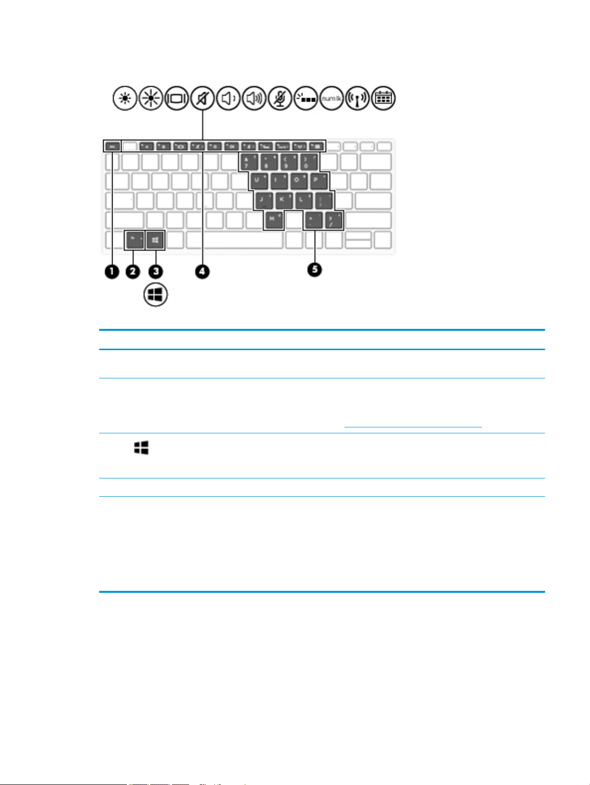
Special keys
Table 2-7 Special keys and their descriptions
Component Description
(1) esc key Displays system information when pressed in combination with
the fn key.
(2) fn key Executes frequently used system functions when pressed in
combination with another key. Such key combinations are called
hot keys.
See Hot keys (select products only) on page 14.
(3) Windows key Opens the Start menu.
NOTE: Pressing the Windows key again will close the Start
menu.
(4) Action keys Execute frequently used system functions.
(5) Embedded numeric keypad A numeric keypad superimposed over the keyboard alphabet
keys. When fn+num lk is pressed, the keypad can be used like an
external numeric keypad. Each key on the keypad performs the
function indicated by the icon in the upper-right corner of the
key.
NOTE: If the keypad function is active when the computer is
turned o, that function is reinstated when the computer is
turned back on.
Keyboard area 13

Hot keys (select products only)
A hot key is the combination of the fn key and another key.
To use a hot key:
▲ Press the fn key, and then press one of the keys listed in the following table.
Table 2-8 Hot keys and their descriptions
Key Description
C Turns on scroll lock.
E Turns on the insert function.
R Breaks the operation.
S Sends a programing query.
W Pauses the operation.
Bottom
Table 2-9 Bottom components and their descriptions
Component Description
Vent Enables airow to cool internal components.
14 Chapter 2 Components
NOTE: The computer fan starts up automatically to cool
internal components and prevent overheating. It is normal
for the internal fan to cycle on and o during routine
operation.
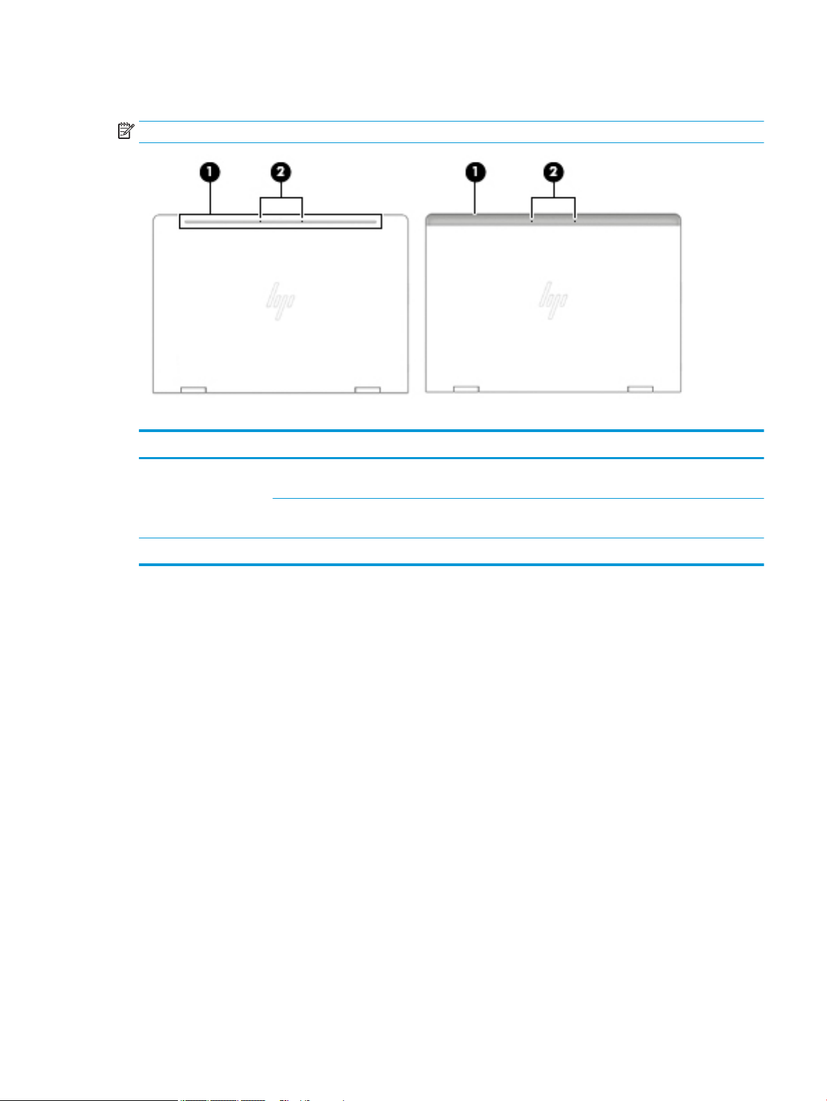
Top
NOTE: Refer to the illustration that most closely matches your computer.
Table 2-10 Top components and their descriptions
Component Description
(1) WLAN antennas Send and receive wireless signals to communicate with
wireless local area networks (WLANs).
WWAN antennas (select products only) Send and receive wireless signals to communicate with
wireless wide area networks (WWANs).
(2) Internal microphones Record sound.
Top 15
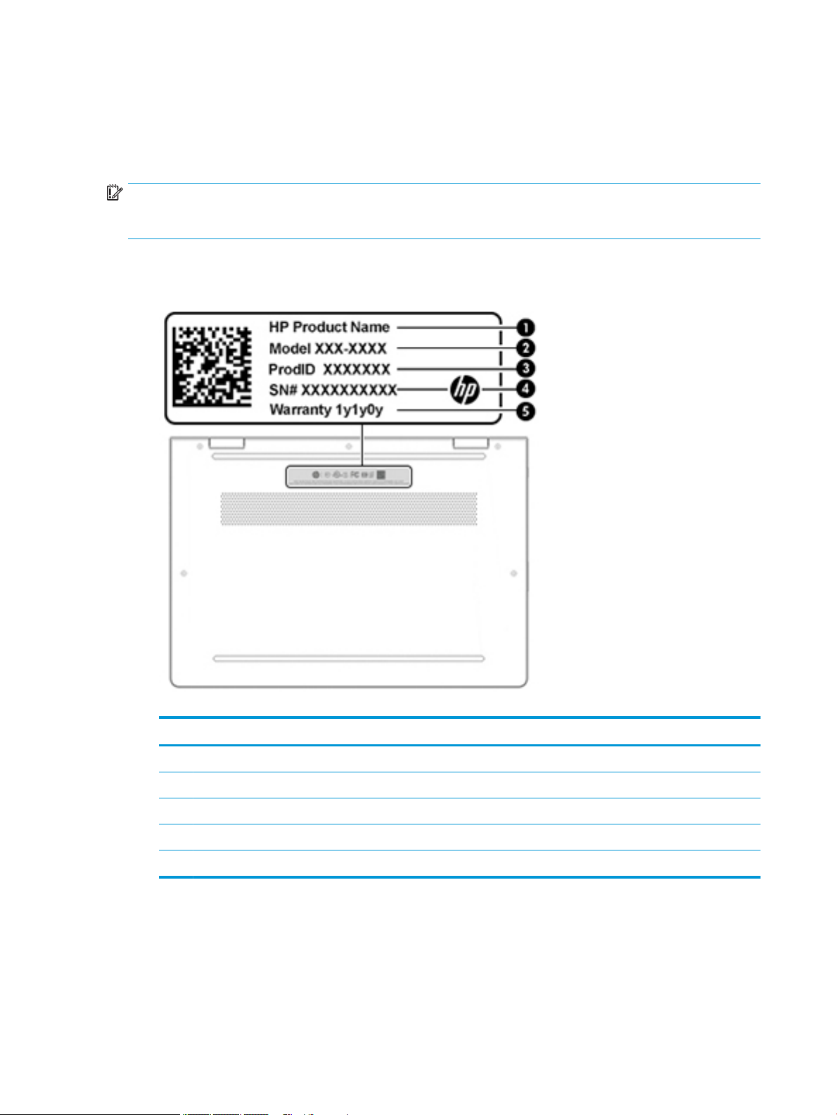
Labels
The labels axed to the computer provide information you may need when you troubleshoot system
problems or travel internationally with the computer. Labels may be in paper form or imprinted on the
product.
IMPORTANT: Check the following locations for the labels described in this section: the bottom of the
computer, inside the battery bay, under the service door, on the back of the display, or on the bottom of a
tablet kickstand.
● Service label—Provides important information to identify your computer. When contacting support, you
may be asked for the serial number, the product number, or the model number. Locate this information
before you contact support.
Table 2-11 Identifying the service label
Component
(1) HP product name
(2) Model number
(3) Product ID
(4) Serial number
(5) Warranty period
● Regulatory label(s)—Provide(s) regulatory information about the computer.
● Wireless certication label(s)—Provide(s) information about optional wireless devices and the approval
markings for the countries or regions in which the devices have been approved for use.
16 Chapter 2 Components
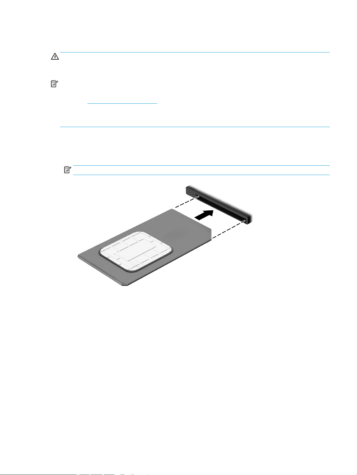
Inserting a SIM card (select products only)
CAUTION: Inserting a SIM card of the wrong size could damage the SIM card or cause the SIM card to become
stuck in the slot. The use of SIM card adapters is not recommended. To prevent damage to the SIM card or the
connectors, use minimal force when inserting or removing a SIM card.
NOTE: Before purchasing a SIM card, follow these instructions to determine the correct SIM card size for
your computer:
1. Go to http://www.hp.com/support, and then search for your computer by product name or number.
2. Select Product Information.
3. Refer to the listed options to determine which card to purchase.
To insert a SIM card, follow these steps:
1. Turn o the computer by using the Shut down command.
2. Insert the SIM card into the SIM card slot, and then press in on the SIM card until it is rmly seated.
NOTE: The SIM card in your computer may look slightly dierent from the illustration in this section.
To remove a SIM card, press in on the SIM card, and then remove it from the slot.
Inserting a SIM card (select products only) 17
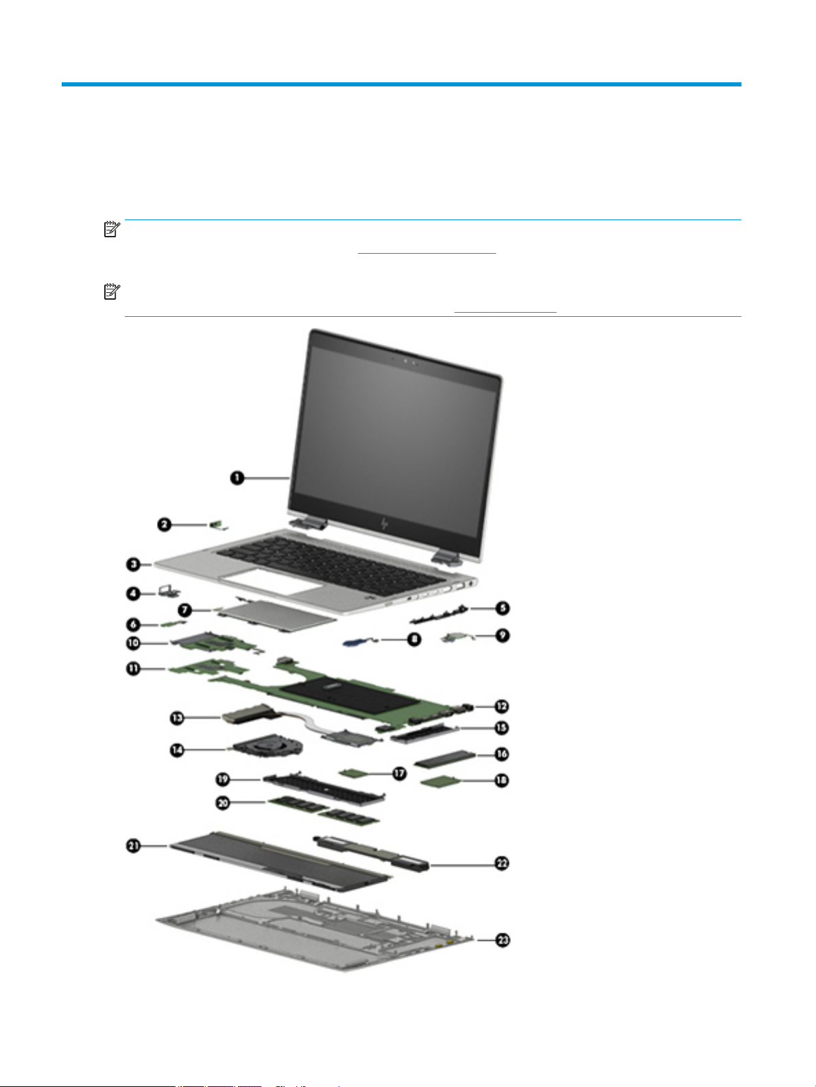
3 Illustrated parts catalog
Computer major components
NOTE: HP continually improves and changes product parts. For complete and current information on
supported parts for your computer, go to http://partsurfer.hp.com, select your country or region, and then
follow the on-screen instructions.
NOTE: Details about your computer, including model, serial number, product key, and length of warranty,
are on the service tag at the bottom of your computer. See Labels on page 16 for details.
18 Chapter 3 Illustrated parts catalog

Table 3-1 Computer major component part numbers and their descriptions
Item Component Spare part number
(1) Display assembly, touch screen:
220 nits L56434-001
220 nits, WWAN L56435-001
400 nits L56436-001
400 nits, WWAN L56437-001
400 nits, WWAN, anti glare L56438-001
1000 nits, BrightView, WWAN, privacy L56439-001
1000 nits, BrightView, privacy L56440-001
1000 nits, WWAN, anti glare, privacy L56441-001
(2) Power button board (includes holder and cable) L56451-001
(3) Keyboard/top cover (includes keyboard cable):
For a detailed list of country codes, see Top cover with keyboard on page 60.
Non-privacy L56442-xx1
Privacy L56443-xx1
(4) Metal USB port bracket (included in Bracket Kit) L56447-001 (Bracket Kit)
(5) Plastic I/O port bracket (included in Plastics Kit) L56454-001 (Plastics Kit)
(6) NFC board (includes cable) L56453-001
(7) TouchPad (includes TouchPad cable):
For use in models with NFC (includes NFC antenna) L56457-001
For use in models without NFC L56458-001
(8) RTC battery not spared
(9) Fingerprint sensor (includes cable and gasket) L56446-001
(10) Card reader board L56452-001
(11) NFC interface board (includes cable) L59058-001
(12) System board (includes processor and replacement thermal material):
All system boards use the following part numbers:
xxxxxx-001: Non-Windows operating system
xxxxxx-601: Windows 10 operating system
Intel Core i7-8650U processor L56433-xx1
Intel Core i7-8650U processor (On Storage Recovery [OSR]) L56432-xx1
Intel Core i7-8550U processor L56431-xx1
Intel Core i5-8350U processor L56429-xx1
Intel Core i5-8250U processor L56430-xx1
Intel Core i3-8130U processor L56428-xx1
Computer major components 19
 Loading...