

Page 1

HP EliteBook 2530p Notebook PC
Maintenance and Service Guide
Page 2

© Copyright 2010 Hewlett-Packard
Development Company, L.P.
© Copyright 2008 Hewlett-Packard
Development Company, L.P.
Bluetooth is a trademark owned by its
proprietor and used by Hewlett-Packard
Company under license. Intel and Core are
trademarks of Intel Corporation in the U.S.
and other countries. Java is a US
trademark of Sun Microsystems, Inc.
Microsoft, Windows, Windows XP, and
Windows Vista are U.S. registered
trademarks of Microsoft Corporation. SD
Logo is a trademark of its proprietor.
The information contained herein is subject
to change without notice. The only
warranties for HP products and services are
set forth in the express warranty statements
accompanying such products and services.
Nothing herein should be construed as
constituting an additional warranty. HP shall
not be liable for technical or editorial errors
or omissions contained herein.
Third Edition: February 2010
Second Edition: October 2008
First Edition: September 2008
Document Part Number: 486606-003
Page 3

Safety warning notice
WARNING! To reduce the possibility of heat-related injuries or of overheating the computer, do not
place the computer directly on your lap or obstruct the computer air vents. Use the computer only on
a hard, flat surface. Do not allow another hard surface, such as an adjoining optional printer, or a soft
surface, such as pillows or rugs or clothing, to block airflow. Also, do not allow the AC adapter to
contact the skin or a soft surface, such as pillows or rugs or clothing, during operation. The computer
and the AC adapter comply with the user-accessible surface temperature limits defined by the
International Standard for Safety of Information Technology Equipment (IEC 60950).
iii
Page 4

iv Safety warning notice
Page 5

Table of contents
1 Product description ........................................................................................................................................ 1
2 External component identification ................................................................................................................ 5
Top components ................................................................................................................................... 5
Pointing devices ................................................................................................................... 5
Lights ................................................................................................................................... 6
Buttons, switches, and fingerprint reader ............................................................................ 8
Keys ................................................................................................................................... 10
Display ............................................................................................................................... 11
Front components .............................................................................................................................. 12
Rear components ............................................................................................................................... 13
Right-side components ....................................................................................................................... 14
Left-side components ......................................................................................................................... 15
Bottom components ........................................................................................................................... 16
Wireless antennae (select models only) ............................................................................................. 18
3 Illustrated parts catalog ............................................................................................................................... 19
Serial number location ........................................................................................................................ 19
Computer major components ............................................................................................................. 21
Display components ........................................................................................................................... 27
Mass storage ...................................................................................................................................... 29
Plastics Kit .......................................................................................................................................... 31
Miscellaneous parts ............................................................................................................................ 32
Sequential part number listing ............................................................................................................ 33
4 Removal and replacement procedures ....................................................................................................... 37
Preliminary replacement requirements ............................................................................................... 37
Tools required .................................................................................................................... 37
Service considerations ....................................................................................................... 37
Plastic parts ....................................................................................................... 37
Cables and connectors ..................................................................................... 38
Drive handling ................................................................................................... 38
Grounding guidelines ......................................................................................................... 39
v
Page 6

Electrostatic discharge damage ........................................................................ 39
Packaging and transporting guidelines ............................................. 40
Workstation guidelines ..................................................................... 40
Equipment guidelines ....................................................................... 41
Unknown user password ................................................................................................... 42
Component replacement procedures ................................................................................................. 43
Service tag ......................................................................................................................... 44
Computer feet .................................................................................................................... 45
Battery ............................................................................................................................... 46
SIM .................................................................................................................................... 47
Bluetooth module ............................................................................................................... 48
Expansion memory module ............................................................................................... 50
WLAN module .................................................................................................................... 52
Primary hard drive ............................................................................................................. 55
WWAN module .................................................................................................................. 58
Optical drive ....................................................................................................................... 60
Switch cover and keyboard ................................................................................................ 62
RTC battery ....................................................................................................................... 66
Secondary hard drive ......................................................................................................... 67
Primary memory module .................................................................................................... 72
Display assembly ............................................................................................................... 73
Top cover ........................................................................................................................... 79
LED board .......................................................................................................................... 82
Speaker ............................................................................................................................. 84
Bluetooth module cable ..................................................................................................... 85
System board ..................................................................................................................... 86
ExpressCard assembly ...................................................................................................... 88
Modem module .................................................................................................................. 90
Fan ..................................................................................................................................... 92
Heat sink ............................................................................................................................ 94
5 Computer Setup ............................................................................................................................................ 96
Starting Computer Setup .................................................................................................................... 96
Using Computer Setup ....................................................................................................................... 97
Navigating and selecting in Computer Setup ..................................................................... 97
Restoring factory settings in Computer Setup ................................................................... 98
Computer Setup menus ..................................................................................................................... 99
File menu ........................................................................................................................... 99
Security menu .................................................................................................................. 100
Diagnostics menu ............................................................................................................ 101
System Configuration menu ............................................................................................ 102
vi
Page 7

6 Specifications .............................................................................................................................................. 105
Computer specifications ................................................................................................................... 105
12.1-inch, WXGA display specifications ........................................................................................... 106
Hard drive specifications .................................................................................................................. 107
DVD-ROM Drive specifications ........................................................................................................ 108
DVD±RW and CD-RW SuperMulti Double-Layer Combo Drive specifications ................................ 109
System DMA specifications .............................................................................................................. 110
System interrupt specifications ......................................................................................................... 111
System I/O address specifications ................................................................................................... 112
System memory map specifications ................................................................................................. 114
7 Screw listing ................................................................................................................................................ 115
Phillips PM 2.0×4.0 screw ................................................................................................................ 116
Torx T8M2.0×5.0 screw ................................................................................................................... 120
Torx T8M2.0×6.0 captive screw ....................................................................................................... 123
Phillips PM2.5×4.0 screw ................................................................................................................. 124
Phillips PM2.5×6.0 captive screw ..................................................................................................... 125
Phillips PM2.5×6.0 screw ................................................................................................................. 126
Torx T8M2.5×6.0 screw ................................................................................................................... 128
Torx T8M2.5×9.0 captive screw ....................................................................................................... 130
Phillips PM2.5×11.0 captive screw ................................................................................................... 131
8 Backup and recovery .................................................................................................................................. 132
Backup and recovery in Windows Vista ........................................................................................... 132
Overview .......................................................................................................................... 132
Backing up your information ............................................................................................ 133
Performing a recovery ..................................................................................................... 134
Using the Windows recovery tools .................................................................. 134
Using f11 ......................................................................................................... 135
Using a Windows Vista operating system DVD (purchased separately) ......... 135
Backup and recovery in Windows XP .............................................................................................. 136
Overview .......................................................................................................................... 136
Backing up your information ............................................................................................ 137
Performing a recovery ..................................................................................................... 138
Recovering your information ........................................................................... 138
Recovering the operating system and programs ............................................ 138
9 Connector pin assignments ....................................................................................................................... 139
Audio-in (microphone) ...................................................................................................................... 139
Audio-out (headphone) ..................................................................................................................... 140
External monitor ............................................................................................................................... 141
IEEE 1394 (FireWire) ....................................................................................................................... 142
RJ-11 (modem) ................................................................................................................................ 143
vii
Page 8

RJ-45 (network) ................................................................................................................................ 144
Universal Serial Bus ......................................................................................................................... 145
10 Power cord set requirements .................................................................................................................. 146
Requirements for all countries and regions ...................................................................................... 146
Requirements for specific countries and regions ............................................................................. 147
11 Recycling ................................................................................................................................................... 148
Battery .............................................................................................................................................. 148
Display .............................................................................................................................................. 149
Index ................................................................................................................................................................. 155
viii
Page 9

1 Product description
Category Description
Product Name HP EliteBook 2530p Notebook PC
Processors Intel® LV Core™2 Duo, soldered uFBGA
SL9600 2.13-GHz, 1066MHZ front side bus (FSB) with 6-MB cache
●
SL9400 1.86-GHz, 1066MHz FSB with 6-MB cache
●
● SL9300 1.6-GHz, 1066MHz FSB with 6-MB cache
Intel ULV Core2 Duo, soldered uFBGA
SU9400, 1.4-GHz, 800 MHz, FSB with 3-MB cache
●
SU9300, 1.2-GHz, 800MHz FSB with 3-MB cache
●
Chipset Mobile Intel Express GS45
ICH9m-SFF-enhanced
Graphics Intel Universal Memory Architecture (UMA) graphics subsystem integrated with up to 384-MB
shared system memory
Panels 12.1-inch WXGA display assembly (1280 × 800) with Antiglare, includes 2 wireless local area
network (WLAN) antennae, and supports privacy filter
Memory Two customer-accessible/upgradable memory module slots
Supports up to 8 GB of system RAM
800-MHz, DDR2
Supports the following configurations:
● 8192-MB total system memory (4096 × 2)
6144-MB total system memory (4096 + 2048)
●
5120-MB total system memory (4096 + 1024)
●
● 4096-MB total system memory (4096 × 1)
4096-MB total system memory (2048 × 2)
●
3072-MB total system memory (2048 + 1024)
●
● 2048-MB total system memory (2048 × 1)
2048-MB total system memory (1024 × 2)
●
1024-MB total system memory (1024 × 1)
●
1
Page 10

Category Description
Hard drives Customer-accessible
Supports the following SATA primary drives:
NOTE: The 4.57-cm (1.80-inch) primary hard drive must be installed in the hard drive bay.
Installation of this drive in the optical drive bay is not supported.
160-GB, 5400-rpm
●
120-GB, 5400-rpm
●
● 80-GB, 5400-rpm
Supports the following primary solid-state drive:
80-GB, Intel
●
Supports the following SATA secondary drives installed in the optical drive bay:
NOTE: The 6.35-cm (2.50-inch) secondary hard drive must be installed in the optical drive bay.
Installation of this drive in the hard drive bay is not supported. (This option is not available when
the optical drive is installed.)
● 320-GB, 7200-rpm
250-GB, 5400-rpm
●
160-GB, 7200-rpm
●
● 160-GB, 5400-rpm
120-GB, 5400-rpm
●
Optical drives Fixed (removal of 1 screw required)
NOTE: This option is not available with a secondary hard drive installed as primary storage.
Customer-accessible
Serial ATA (SATA)
9.5-mm tray load
Supports the following drive options:
DVD-ROM Drive
●
DVD±RW and CD-RW SuperMulti Double-Layer Combo Drive
●
● No optical drive, with optical drive space-saver
Diskette drive Supports external USB diskette drive only
Supports boot from external USB diskette drive
Audio HD audio - ADI1984A
Integrated single speaker, no speaker branding
Integrated dual-array microphone
Webcam Optional 2.1-megapixel webcam with support for a business card reader
Modem 56K V.92 data/fax modem
Ethernet Integrated Gigabit 10/100/1000 local access network (LAN)
2 Chapter 1 Product description
Page 11

Category Description
S4/S5 wake on LAN on AC power
NIC power-down technology
Wireless LAN Integrated WLAN options by way of mini-slot which supports WLAN only:
Support for 2 dual-band 2.4-/5.0-GHz WLAN antennae cabled to mini-slot
Support for the following WLAN options:
● 802.11a/b/g with Intel Active Management Technology (iAMT) support
802.11a/b/g/n with iAMT support
●
802.11a/b/g/draft-n
●
● 802.11b/g
no-WLAN option
●
Integrated WWAN options by way of mini-slot which supports WWAN only:
Support for 2 five-band WWAN antennae cabled to mini-slot
SIM is user-accessible behind battery
Supports the following WWAN options:
HP un2400 Mobile Broadband Module
●
WWAN aftermarket option
●
Integrated WPAN option by way of mini-slot which supports WPAN only:
Supports no-wireless PAN option
Blueflame Bluetooth® module
External media card SD Card Reader supporting Secure Digital (SD) Memory Card and MultiMediaCard (MMC)
Ports Audio-in (stereo microphone)
Audio-out (stereo headphone)
Docking
RJ-11 (modem)
RJ-45 (Ethernet, includes link and activity lights)
USB (2 ports on models with an optical drive installed, 3 ports on models without an optical drive
installed)
VGA (Dsub 15-pin) supporting 1600 × 1200 external resolution at 75-GHz (hot plug/unplug with
auto-detect)
3-pin AC power via the HP Smart AC Adapter
Docking HP 2400/2500 Series Docking Station
Keyboard/pointing
devices
Full–size 4.5-mm×19.05-mm keyboard with embedded numeric keypad
Pointing stick with 2 pointing stick buttons
TouchPad with 2 TouchPad buttons and vertical scrolling zone
3
Page 12

Category Description
Spill-resistant keyboard
Windows Vista® Start button
Durable key caps
Power requirements 65-W Smart AC adapter with localized cable plug support (3-wire plug with ground pin)
9-cell, 83.0-Wh Li-ion battery with fuel gauge
6-cell, 55.0-Wh Li-ion battery with fuel gauge
3-cell, 31.0-Wh Li-ion battery
Security Supports Kensington security lock
Supports integrated USB-based fingerprint reader
Operating system Preinstalled:
Vista Home Basic (32-bit)
Vista Business (32-bit)
Vista Ultimate (32-bit)
FreeDOS
Serviceability End-user replaceable parts:
AC adapter and power cord
Battery (system)
SIM
Bluetooth module
Memory module
WLAN module
WWAN module
Optical drive
RTC battery
Switch cover
Keyboard
Primary hard drive
Primary hard drive (solid-state)
NOTE: The 4.57-cm (1.80-inch) primary hard drive must be installed in the hard drive bay.
Secondary hard drive
NOTE: The 6.35-cm (2.50-inch) secondary hard drive must be installed in the optical drive bay.
Installation of this drive in the optical drive bay is not supported.
Installation of this drive in the hard drive bay is not supported. (This option is not available when
the optical drive is installed.)
4 Chapter 1 Product description
Page 13
2 External component identification
Top components
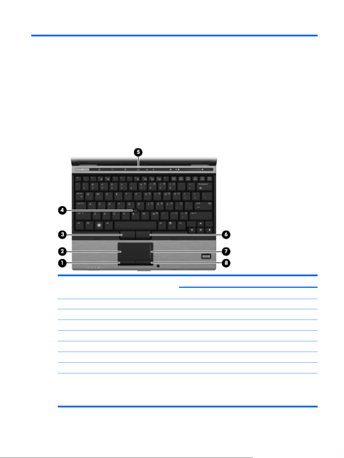
Pointing devices
Component Description
(1) Left TouchPad button* Functions like the left button on an external mouse.
(2) TouchPad* Moves the pointer and selects or activates items on the screen.
(3) Left pointing stick button* Functions like the left button on an external mouse.
(4) Pointing stick* Moves the pointer and selects or activates items on the screen.
(5) TouchPad on/off button Turns the TouchPad on and off.
(6) Right pointing stick button* Functions like the right button on an external mouse.
(7) TouchPad scroll zone Scrolls up or down.
(8) Right TouchPad button* Functions like the right button on an external mouse.
*This table describes factory settings. To view or change pointing device preferences:
● For Windows Vista, select Start > Control Panel > Hardware and Sound > Mouse.
For Windows® XP, select Start > Control Panel > Printers and Other Hardware > Mouse.
●
Top components 5
Page 14
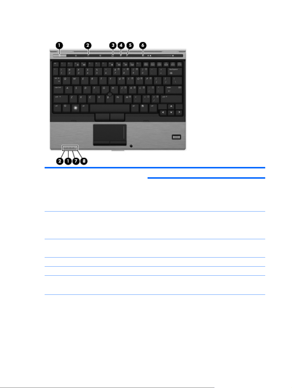
Lights
Component Description
(1) Power lights (2)* ● On: The computer is on.
Blinking: The computer is in the Sleep state (Windows
●
Vista) or Standby (Windows XP).
Off: The computer is off or in Hibernation.
●
(2) Wireless lights (2)† ● Blue: An integrated wireless device, such as a wireless local
(3) TouchPad on/off light
(4) Caps lock light On: Caps lock is on.
(5) Num lock light On: Num lock is on or the embedded numeric keypad is enabled.
(6) Volume mute light ● Turquoise: Speaker sound is on.
area network (WLAN) device, the HP Mobile Broadband
Module, and/or a Bluetooth device, is on.
● Amber: All wireless devices are off.
Turquoise: TouchPad is on.
●
● Amber: TouchPad is off.
Amber: Speaker sound is off.
●
6 Chapter 2 External component identification
Page 15

Component Description
(7) Battery light ● Amber: A battery is charging.
Turquoise: A battery is close to full charge capacity.
●
Blinking amber: A battery that is the only available power
●
source has reached a low battery level. When the battery
reaches a critical battery level, the battery light begins
blinking rapidly.
● Off: If the computer is plugged into an external power
source, the light turns off when all batteries in the computer
are fully charged. If the computer is not plugged into an
external power source, the light stays off until the battery
reaches a low battery level.
(8) Drive light ● Blinking turquoise: The hard drive or optical drive is being
*The 2 power lights display the same information. The light on the power button is visible only when the computer is open.
The power light on the front of the computer is visible whether the computer is open or closed.
†The 2 wireless lights display the same information. The light on the wireless button is visible only when the computer is
open. The wireless light on the front of the computer is visible whether the computer is open or closed.
accessed.
Amber: HP 3D DriveGuard has temporarily parked the
●
internal hard drive.
Top components 7
Page 16
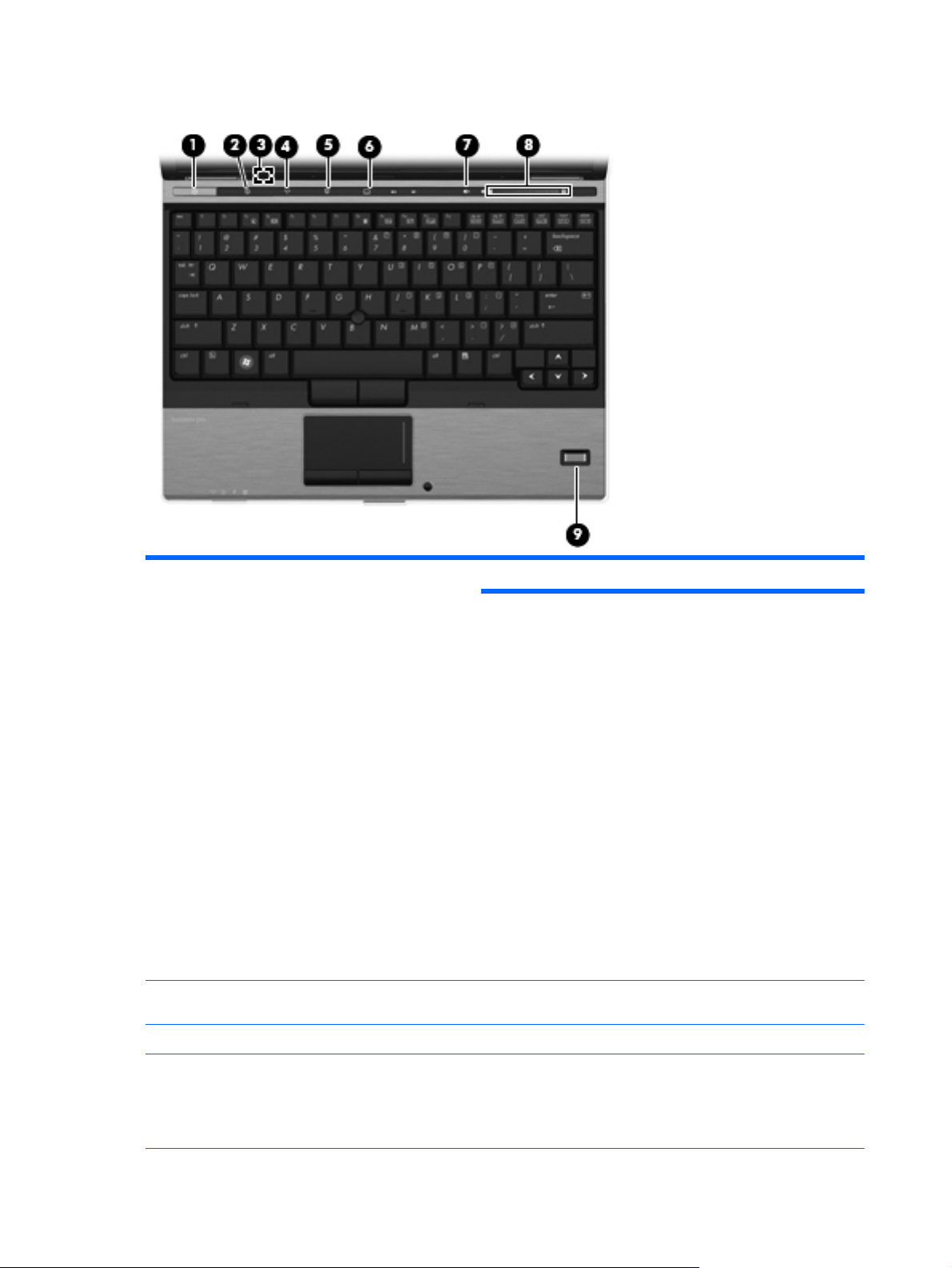
Buttons, switches, and fingerprint reader
Component Description
(1) Power button ● When the computer is off, press the button to turn on the
(2) Info button Launches Info Center, which enables you to open various
computer.
● When the computer is on, press the button to shut down the
computer.
When the computer is in the Sleep state (Windows Vista) or
●
Standby (Windows XP), press the button briefly to exit the
Sleep state or Standby.
When the computer is in Hibernation, press the button
●
briefly to exit Hibernation.
If the computer has stopped responding and Windows®
shutdown procedures are ineffective, press and hold the power
button for at least 5 seconds to turn off the computer.
To learn more about your power settings:
For Windows Vista, select Start > Control Panel > System
●
and Maintenance > Power Options.
For Windows XP, select Start > Control Panel >
●
Performance and Maintenance > Power Options.
software solutions.
(3) Internal display switch Turns off the display if the display is closed while the power is on.
(4) Wireless button Turns the wireless feature on or off but does not establish a
8 Chapter 2 External component identification
wireless connection.
NOTE: A wireless network must be set up in order to establish
a wireless connection.
Page 17

Component Description
(5) Presentation button Starts the presentation feature.
(6) TouchPad on/off button Turns the TouchPad on or off.
(7) Volume mute button Mutes and restores speaker sound.
(8) Volume scroll zone Adjusts speaker volume. Slide your finger to the left to decrease
(9) Fingerprint reader Allows a fingerprint logon to Windows, instead of a password
volume and to the right to increase volume. You can also press
and hold the minus (–) sign to decrease volume, or press and
hold the plus (+) sign to increase volume.
logon.
Top components 9
Page 18
Keys
Component Description
(1) esc key Displays system information when pressed in combination with
(2) fn key Executes frequently used system functions when pressed in
(3) Windows logo key Displays the Windows Start menu.
(4) Windows applications key Displays a shortcut menu for items beneath the pointer.
(5) Embedded numeric keypad keys Can be used like the keys on an external numeric keypad.
(6) Function keys Execute frequently used system functions when pressed in
the fn key.
combination with a function key or the esc key.
combination with the fn key.
10 Chapter 2 External component identification
Page 19
Display
Component Description
(1) Ambient light sensor Automatically adjusts the display brightness based on the lighting
conditions in your environment.
(2) Webcam light (select models only) On: The integrated camera is in use.
(3) Webcam (select models only) Records audio and video and captures still photographs.
(4) Keyboard light Illuminates the keyboard in low-light conditions when the
(5) Keyboard light button Opens and turns on the keyboard light.
(6) Internal microphone Records sound.
keyboard light button is pressed.
NOTE: The internal microphone makes use of dual array
technology, which provides speech enhancement and
suppresses surrounding noises.
Top components 11
Page 20

Front components
Component Description
(1) Wireless light ● Blue: An integrated wireless device, such as a wireless
(2) Power light ● On: The computer is on.
(3) Battery light
(4) Drive light
local area network (WLAN) device, the HP Mobile
Broadband Module, and/or a Bluetooth device, is on.
● Amber: All wireless devices are off.
Blinking: The computer is in the Sleep state (Windows
●
Vista) or Standby (Windows XP).
Off: The computer is off or in Hibernation.
●
Amber: A battery is charging.
●
● Turquoise: A battery is close to full charge capacity.
Blinking amber: A battery that is the only available power
●
source has reached a low battery level. When the battery
reaches a critical battery level, the battery light begins
blinking rapidly.
Off: If the computer is plugged into an external power
●
source, the light turns off when all batteries in the computer
are fully charged. If the computer is not plugged into an
external power source, the light stays off until the battery
reaches a low battery level.
Turquoise: The hard drive or optical drive is being
●
accessed.
(5) Business card slot Holds a business card in position so that the webcam can
(6) Display release button Opens the computer.
12 Chapter 2 External component identification
● Amber: HP 3D DriveGuard has temporarily parked the
internal hard drive.
capture the information on the card.
Page 21

Rear components
Component Description
(1) RJ-45 (network) jack Connects a network cable.
(2) Security cable slot Attaches an optional security cable to the computer.
NOTE: The security cable is designed to act as a deterrent, but
it may not prevent the computer from being mishandled or stolen.
Rear components 13
Page 22
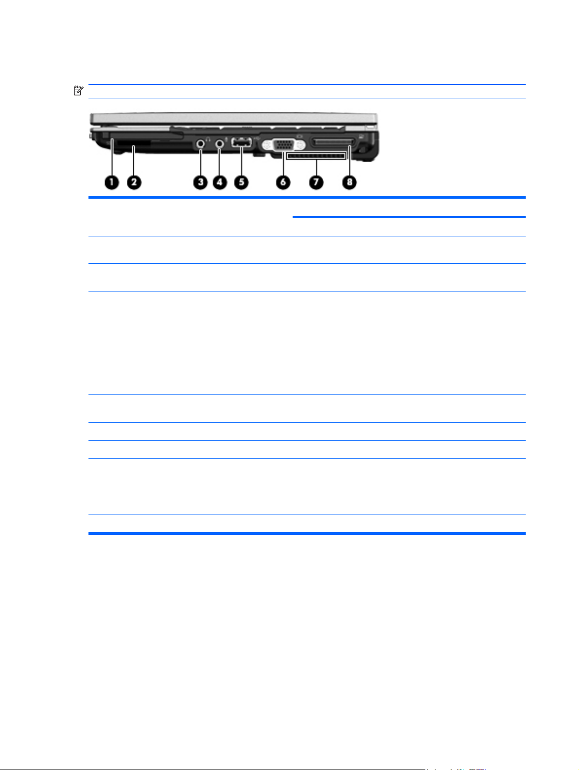
Right-side components
NOTE: Refer to the illustration that most closely matches your computer.
Component Description
(1) ExpressCard slot Supports optional ExpressCards.
(2) SD Card Reader Supports the Secure Digital (SD) Memory Card and
(3) 1394 port Connects an optional IEEE 1394 or 1394a device, such as a
(4) Audio-out (headphone) jack Produces sound when connected to optional powered stereo
MultiMediaCard (MMC) optional digital card formats.
camcorder.
speakers, headphones, ear buds, a headset, or television audio.
WARNING! To reduce the risk of personal injury, adjust the
volume before putting on headphones, earbuds, or a headset.
For additional safety information, refer to the Regulatory, Safety
and Environmental Notices.
NOTE: When a device is connected to the headphone jack, the
computer speakers are disabled.
(5) Audio-in (microphone) jack Connects an optional computer headset microphone, stereo
array microphone, or monaural microphone.
(6) USB port Connects an optional USB device.
(7) External monitor port Connects an external VGA monitor or projector.
(8) Vent Enables airflow to cool internal components.
NOTE: The computer fan starts up automatically to cool internal
components and prevent overheating. It is normal for the internal
fan to cycle on and off during routine operation.
(9) Expansion port 3 Connects an optional docking device.
14 Chapter 2 External component identification
Page 23
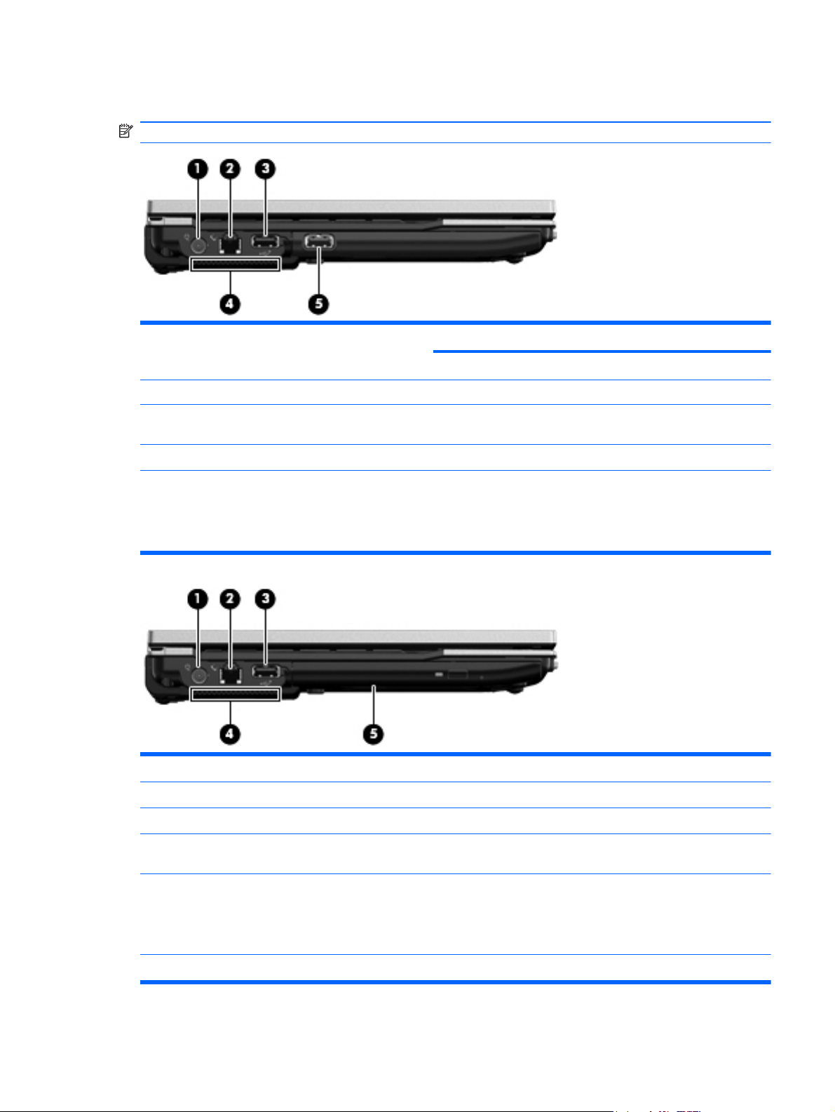
Left-side components
NOTE: Refer to the illustration that most closely matches your computer.
Component Description
(1) Power connector Connects an AC adapter.
(2) RJ-11 (modem) jack Connects a modem cable.
(3) Powered USB port Provides power to an external device if used with a powered USB
(4) USB port Connects an optional USB device.
(5) Vent Enables airflow to cool internal components.
Component Description
(1) Power connector Connects an AC adapter.
(2) RJ-11 (modem) jack Connects a modem cable.
cable.
NOTE: The computer fan starts up automatically to cool internal
components and prevent overheating. It is normal for the internal
fan to cycle on and off during routine operation.
(3) Powered USB port Provides power to an external device if used with a powered
USB cable.
(4) Vent Enables airflow to cool internal components.
NOTE: The computer fan starts up automatically to cool
internal components and prevent overheating. It is normal for the
internal fan to cycle on and off during routine operation.
(5) Optical drive Reads and writes to an optical disc.
Left-side components 15
Page 24
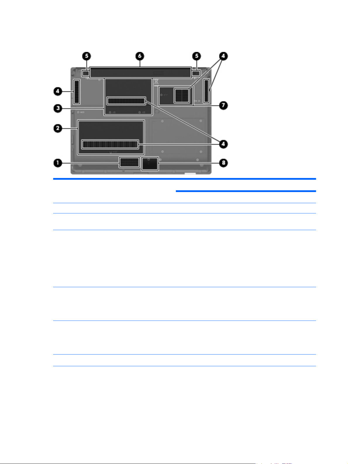
Bottom components
Component Description
(1) Battery release latches (2) Release the battery from the battery bay.
(2) Battery bay Holds the battery.
(3) SIM slot (select models only) Contains a wireless subscriber identity module (SIM). The SIM
(4) Broadband wireless module compartment Contains an HP Mobile Broadband Module (select models only).
(5) Vents (5) Enable airflow to cool internal components.
(6) Hard drive bay Holds the hard drive.
(7) Bluetooth compartment Contains a Bluetooth device.
slot is located inside the battery bay.
CAUTION: To prevent an unresponsive system, replace the
wireless module only with a wireless module authorized for use in
the computer by the governmental agency that regulates wireless
devices in your country or region. If you replace the module and
then receive a warning message, remove the module to restore
computer functionality, and then contact technical support
through Help and Support.
NOTE: The computer fan starts up automatically to cool internal
components and prevent overheating. It is normal for the internal
fan to cycle on and off during routine operation.
NOTE: The 4.57-cm (1.80-inch) primary hard drive must be
installed in the hard drive bay. Installation of this drive in the
optical drive bay is not supported.
16 Chapter 2 External component identification
Page 25

Component Description
(8) Speaker Produces sound.
(9) Memory module compartment Contains an expansion memory module slot and a WLAN module
(select models only).
NOTE: To prevent an unresponsive system, replace the
wireless module only with a wireless module authorized for use in
the computer by the governmental agency that regulates wireless
devices in your country or region. If you replace the module and
then receive a warning message, remove the module to restore
computer functionality, and then contact technical support
through Help and Support.
Bottom components 17
Page 26
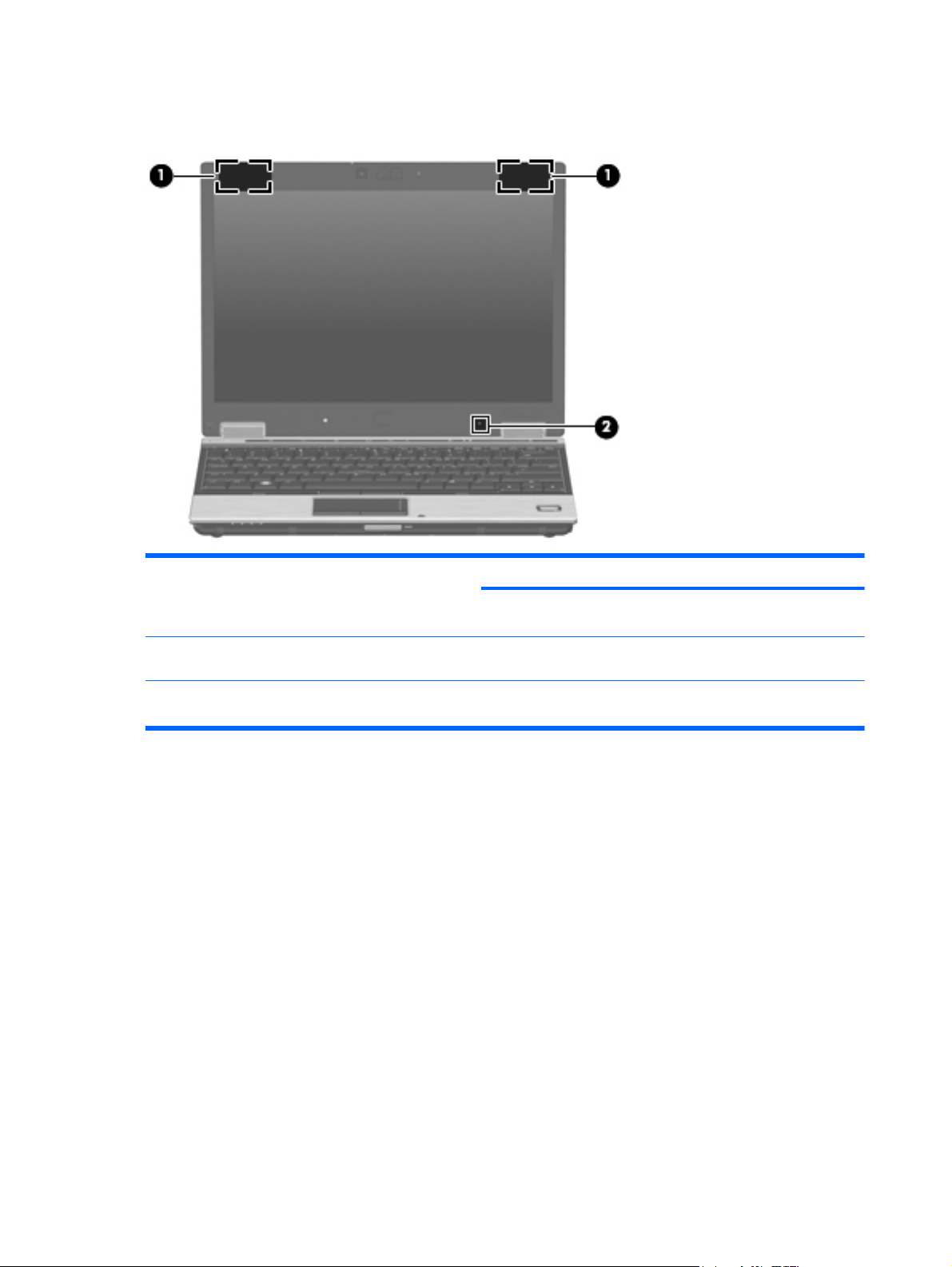
Wireless antennae (select models only)
Component Description
(1) WLAN antennae (2)* Send and receive wireless signals to communicate with wireless
(2) WWAN antennae (2)* Send and receive wireless signals to communicate with wireless
*The antennae are not visible from the outside of the computer. For optimal transmission, keep the areas immediately
around the antennae free from obstructions.
local area networks (WLAN).
wide-area networks (WWAN).
To see wireless regulatory notices, refer to the section of the Regulatory, Safety and Environmental
Notices that applies to your country or region. These notices are located in Help and Support.
18 Chapter 2 External component identification
Page 27

3 Illustrated parts catalog
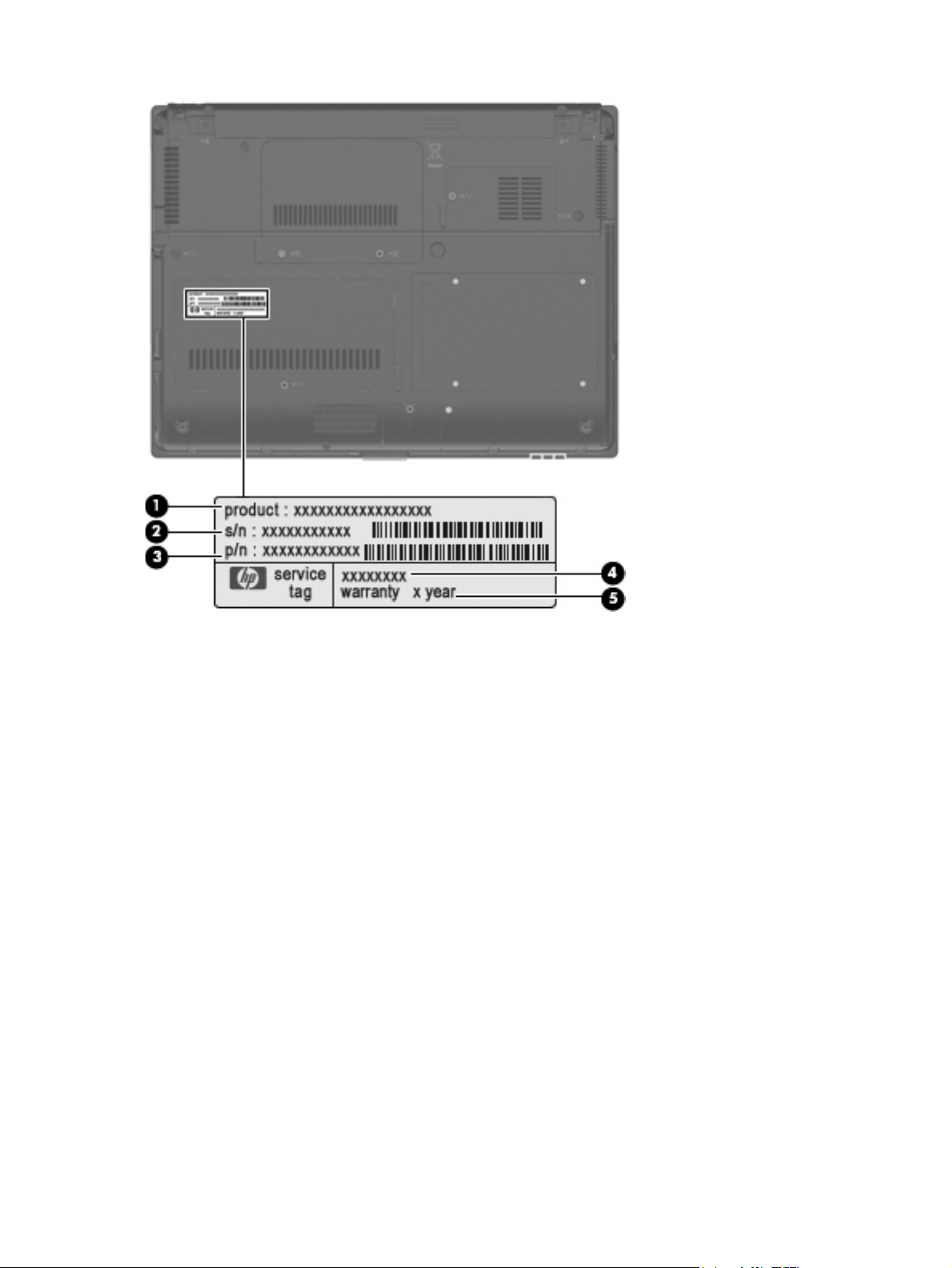
Serial number location
The service tag, affixed to the bottom of the computer, provides information that may be needed
when troubleshooting system problems. The service tag provides the following information:
(1) Product name: This is the product name affixed to the front of the computer.
(2) Serial number (s/n): This is an alphanumeric identifier that is unique to each product.
(3) Part number/Product number (p/n): This number provides specific information about the product's
hardware components. The part number helps a service technician to determine what components
and parts are needed.
(4) Model description: This is the number used to locate documents, drivers, and support for the
computer.
(5) Warranty period: This number describes the duration of the warranty period for the computer.
When ordering parts or requesting information, provide the computer serial number and model
description provided on the service tag.
Serial number location 19
Page 28
20 Chapter 3 Illustrated parts catalog
Page 29
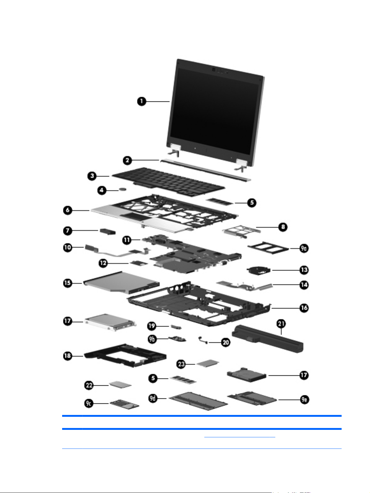
Computer major components
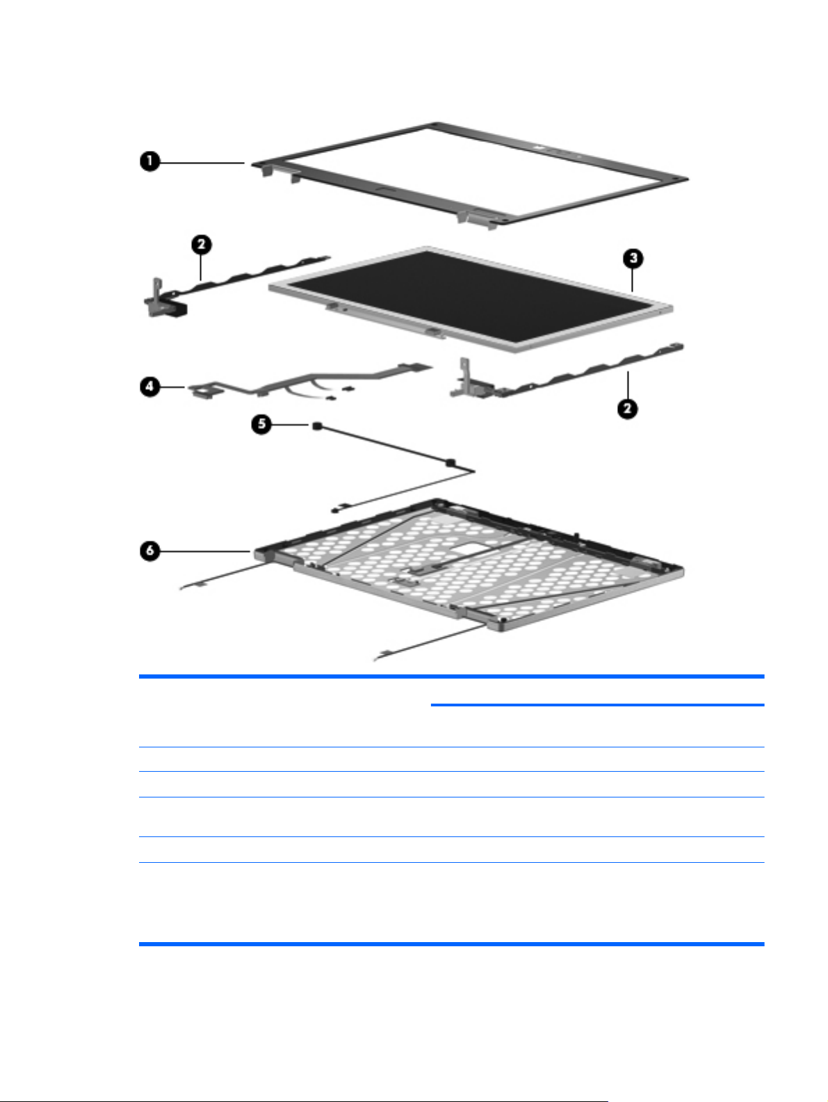
Item Description Spare part number
(1) 12.1-inch, WXGA AntiGlare display assembly (See
component spare part number information.)
Display components on page 27 for display assembly
Computer major components 21
Page 30

Item Description Spare part number
With webcam 492576-001
Without webcam 492575-001
(2) Switch cover (includes display lid switch board and cable and LED board and cable) 492556-001
(3) Keyboard with pointing stick (includes keyboard cable and pointing stick cable)
● For use in the Czech Republic 506677-221
● For use in Denmark 506677-081
● For use in Finland and Sweden 506677-B71
● For use in France 506677-051
● For use in Germany 506677-041
● For use in Greece 506677-151
● For use in Iceland 506677-DD1
● For use in Israel 506677-BB1
● For use in Japan 506677-291
● For use in Latin America 506677-161
For use in Brazil 506677-201
●
For use in Europe 506677-021
●
For use in French Canada 506677-121
●
For use in Hungary 506677-211
●
For use in Italy 506677-061
●
For use in the Netherlands and Europe 506677-A41
●
● For use in Norway 506677-091
● For use in Portugal 506677-131
● For use in Saudi Arabia 506677-171
● For use in Slovakia 506677-231
● For use in Spain 506677-071
● For use in Switzerland 506677-111
● For use in Thailand 506677-281
● For use in Turkey 506677-141
(4) RTC battery 481089-001
For use in Russia 506677-251
●
For use in South Korea 506677-AD1
●
For use in Taiwan 506677-AB1
●
For use in the United Kingdom 506677-031
●
● For use in the United States 506677-001
22 Chapter 3 Illustrated parts catalog
Page 31

Item Description Spare part number
(5) Memory modules (2, PC2-6400, 800-MHz, DDR2)
4-GB 492572-001
2-GB 492571-001
1-GB 492570-001
(6) Top cover (includes TouchPad board and cable, TouchPad button board and cable, and
TouchPad bracket)
With fingerprint reader 492557-001
Without fingerprint reader 514059-001
(7) Speaker 481109-001
(8) ExpressCard assembly 492567-001
Plastics Kit (See
(9a) ExpressCard slot bezel
(9b) Bluetooth module compartment cover
(9c) Wireless module compartment cover
(9d) Memory module compartment cover
(9e) Hard drive cover
NOTE: The 4.57-cm (1.80-inch) primary hard drive must be installed in the hard drive bay. Installation of this drive
in the optical drive bay is not supported.
(10) LED board (includes cable and Mylar cover) 499209-001
(11) System board (includes processor, replacement thermal material, and replacement
thermal material cleaning kit)
With LV SL9600 processor 513947-001
Plastics Kit on page 31 for more Plastics Kit spare part information): 492577-001
With LV SL9400 processor 492552-001
With LV SL9300 processor 492551-001
With ULV SU9400 processor 513946-001
With ULV SU9300 processor 492553-001
(12) Modem module
NOTE: The modem module spare part kit does not include a modem module cable. The modem module cable is
included in the Cable Kit, spare part number 492555-001.
For use in all countries and regions except Australia and New Zealand 461750-001
For use only in Australia and New Zealand 461750-011
(13) Fan 492568-001
(14) Heat sink (includes replacement thermal material and replacement thermal material
cleaning kit)
(15) Optical drive (includes bezel and bracket)
DVD±RW and CD-RW SuperMulti Double-Layer Combo Drive 492559-001
492582–001
Computer major components 23
Page 32

Item Description Spare part number
DVD-ROM Drive 492558-001
(16) Base enclosure (includes display latch switch, battery release latch, and rubber feet) 492547-001
(17) Hard drives (2, include bezel and bracket)
Primary hard drive
NOTE: The 4.57-cm (1.80-inch) primary hard drive must be installed in the hard drive bay. Installation of this drive
in the optical drive bay is not supported.
● 160-GB, 5400-rpm hard drive 503732-001
● 120-GB, 5400-rpm hard drive 492560-001
● 80-GB, solid-state hard drive 492566-001
Secondary hard drive
● 320-GB, 7200-rpm hard drive 513949-001
● 250-GB, 5400-rpm hard drive 513948-001
● 160-GB, 5400-rpm hard drive 513950-001
● 120-GB, 5400-prm hard drive 492561-001
(18) Secondary hard drive cage assembly (includes additional USB port; required for
Secondary hard drive connector board (required for installation of secondary hard drive) 495027-001
Secondary hard drive system connector board (required for installation of secondary hard
(19) Bluetooth module 483113-001
(20) Bluetooth module cable (included in the Cable Kit, spare part number 492555-001)
(21) Battery
80-GB, 5400-rpm hard drive 492565-001
●
NOTE: The 6.35-cm (2.50-inch) secondary hard drive must be installed in the optical drive bay. Installation of this
drive in the hard drive bay is not supported. (This option is not available when the optical drive is installed.)
160-GB, 7200-rpm hard drive 492564-001
●
492574-001
installation of secondary hard drive)
drive)
495028-001
9-cell, 83.0-WH Li-ion 492550-001
6-cell, 55.0-WH Li-ion 492549-001
3-cell, 31.0-WH Li-ion 492548-001
(22) WLAN module
802.11a/b/g/n WLAN modules:
Intel WiFi Link 5100ABGN for use in Antigua and Barbuda, Argentina, Aruba,
●
the Bahamas, Barbados, Bermuda, Brunei, Canada, the Cayman Islands, Chile,
Colombia, Costa Rica, the Dominican Republic, Ecuador, El Salvador, Guam,
Guatemala, Haiti, Honduras, Hong Kong, India, Indonesia, Malaysia, Mexico,
Panama, Paraguay, Peru, Saudi Arabia, Taiwan, Uruguay, the United States,
Venezuela, and Vietnam
24 Chapter 3 Illustrated parts catalog
480985-001
Page 33

Item Description Spare part number
● Broadcom 4322AGN WiFi Adapter for use in the United States and Canada 487330-001
Broadcom 4322AGN WiFi Adapter for use in Afghanistan, Albania, Algeria, Andorra,
●
Angola, Antigua and Barbuda, Argentina, Armenia, Aruba, Australia, Austria,
Azerbaijan, the Bahamas, Bahrain, Bangladesh, Barbados, Belarus, Belgium, Belize,
Benin, Bermuda, Bhutan, Bolivia, Bosnia and Herzegovina, Botswana, Brazil,
the British Virgin Islands, Brunei, Bulgaria, Burkina Faso, Burundi, Cambodia,
Cameroon, Cape Verde, the Central African Republic, Chad, Chile, Colombia,
Comoros, the Congo, Costa Rica, Croatia, Cyprus, the Czech Republic, Denmark,
Djibouti, Dominica, the Dominican Republic, East Timor, Ecuador, Egypt, El Salvador,
Equitorial Guinea, Eritrea, Estonia, Ethiopia, Fiji, Finland, France, French Guiana,
Gabon, Gambia, Georgia, Germany, Ghana, Gibraltar, Greece, Grenada,
Guadeloupe, Guatemala, Guinea, Guinea-Bissau, Guyana, Haiti, Honduras,
Hong Kong, Hungary, Iceland, India, Indonesia, Ireland, Israel, Italy, the Ivory Coast,
Jamaica, Jordan, Kazakhstan, Kenya, Kiribati, Kuwait, Kyrgyzstan, Laos, Latvia,
Lebanon, Lesotho, Liberia, Liechtenstein, Lithuania, Luxembourg, Macedonia,
Madagascar, Malawi, Malaysia, the Maldives, Mali, Malta, the Marshall Islands,
Martinique, Mauritania, Mauritius, Mexico, Micronesia, Monaco, Mongolia,
Montenegro, Morocco, Mozambique, Namibia, Nauru, Nepal, the Nether Antilles,
the Netherlands, New Zealand, Nicaragua, Niger, Nigeria, Norway, Oman, Palau,
Panama, Papua New Guinea, Paraguay, the People's Republic of China, Peru,
the Philippines, Poland, Portugal, Qatar, the Republic of Moldova, Romania, Russia,
Rwanda, Samoa, San Marino, Sao Tome and Principe, Saudi Arabia, Senegal,
Serbia, the Seychelles, Sierra Leone, Singapore, Slovakia, Slovenia,
the Solomon Islands, Somalia, South Africa, South Korea, Spain, Sri Lanka,
St. Kitts and Nevis, St. Lucia, St. Vincent and the Grenadines, Suriname, Swaziland,
Sweden, Switzerland, Taiwan, Tajikistan, Tanzania, Thailand, Togo, Tonga,
Trinidad and Tobago, Tunisia, Turkey, Turkmenistan, Tuvalu, Uganda, Ukraine,
the United Arab Emirates, the United Kingdom, Uruguay, Uzbekistan, Vanuatu,
Venezuela, Vietnam, Yemen, Zaire, Zambia, and Zimbabwe
487330-002
● Intel WiFi Link 5100ABGN with Active Management Technology (AMT) for use in
802.11a/b/g WLAN modules:
● Intel WiFi Link 5100ABG with AMT for use in the United States and Canada 506680-001
802.11b/g WLAN modules:
the United States and Canada
Intel WiFi Link 5100ABG for use in the United States and Canada 482957-001
●
506678-001
Computer major components 25
Page 34

Item Description Spare part number
● Broadcom 4312G WiFi Adapter for use in Afghanistan, Albania, Algeria, Andorra,
Angola, Antigua and Barbuda, Argentina, Armenia, Aruba, Australia, Austria,
Azerbaijan, the Bahamas, Bahrain, Bangladesh, Barbados, Belarus, Belgium, Belize,
Benin, Bermuda, Bhutan, Bolivia, Bosnia and Herzegovina, Botswana, Brazil,
the British Virgin Islands, Brunei, Bulgaria, Burkina Faso, Burundi, Cambodia,
Cameroon, Cape Verde, the Central African Republic, Chad, Chile, Colombia,
Comoros, the Congo, Costa Rica, Croatia, Cyprus, the Czech Republic, Denmark,
Djibouti, Dominica, the Dominican Republic, East Timor, Ecuador, Egypt, El Salvador,
Equitorial Guinea, Eritrea, Estonia, Ethiopia, Fiji, Finland, France, French Guiana,
Gabon, Gambia, Georgia, Germany, Ghana, Gibraltar, Greece, Grenada,
Guadeloupe, Guatemala, Guinea, Guinea-Bissau, Guyana, Haiti, Honduras,
Hong Kong, Hungary, Iceland, India, Indonesia, Ireland, Israel, Italy, the Ivory Coast,
Jamaica, Jordan, Kazakhstan, Kenya, Kiribati, Kuwait, Kyrgyzstan, Laos, Latvia,
Lebanon, Lesotho, Liberia, Liechtenstein, Lithuania, Luxembourg, Macedonia,
Madagascar, Malawi, Malaysia, the Maldives, Mali, Malta, the Marshall Islands,
Martinique, Mauritania, Mauritius, Mexico, Micronesia, Monaco, Mongolia,
Montenegro, Morocco, Mozambique, Namibia, Nauru, Nepal, the Nether Antilles,
the Netherlands, New Zealand, Nicaragua, Niger, Nigeria, Norway, Oman, Palau,
Panama, Papua New Guinea, Paraguay, the People's Republic of China, Peru,
the Philippines, Poland, Portugal, Qatar, the Republic of Moldova, Romania, Russia,
Rwanda, Samoa, San Marino, Sao Tome and Principe, Saudi Arabia, Senegal,
Serbia, the Seychelles, Sierra Leone, Singapore, Slovakia, Slovenia,
the Solomon Islands, Somalia, South Africa, South Korea, Spain, Sri Lanka,
St. Kitts and Nevis, St. Lucia, St. Vincent and the Grenadines, Suriname, Swaziland,
Sweden, Switzerland, Taiwan, Tajikistan, Tanzania, Thailand, Togo, Tonga,
Trinidad and Tobago, Tunisia, Turkey, Turkmenistan, Tuvalu, Uganda, Ukraine,
the United Arab Emirates, the United Kingdom, Uruguay, Uzbekistan, Vanuatu,
Venezuela, Vietnam, Yemen, Zaire, Zambia, and Zimbabwe
Broadcom 4312G WiFi Adapter for use in the United States and Canada 459263-001
●
459263-002
(23) HP un2400 Mobile Broadband Module 483377-002
26 Chapter 3 Illustrated parts catalog
Page 35

Display components
Item Description Spare part number
(1) Display bezel (includes HP logo and computer model number label)
For use with models that include a webcam 495022-001
For use with models that do not include a webcam 495019-001
Display bezel adhesive (not illustrated) 497013-001
(2) Display Hinge Kit (includes left and right hinges and brackets) 481098-001
(3) Display panel cable
For use with models that include a webcam 495023-001
For use with models that do not include a webcam 495021-001
(4) Microphone 492573-001
(5) Display enclosure (includes HP logo, wireless antenna transceivers, and cables)
Display components 27
Page 36

Item Description Spare part number
With webcam 496490-001
Without webcam 495020-001
28 Chapter 3 Illustrated parts catalog
Page 37

Mass storage
Item Description Spare part number
(1) Primary hard drive
NOTE: The 4.57-cm (1.80-inch) primary hard drive must be installed in the hard drive bay. Installation of this drive
in the optical drive bay is not supported.
160-GB, 5400-rpm hard drive 503732-001
120-GB, 5400-rpm hard drive 492560-001
80-GB, 5400-rpm hard drive 492565-001
80-GB, solid-state hard drive 492566-001
Primary hard drive connector board (required for installation of primary hard drive) 495026-001
(2) Secondary hard drive
NOTE: The 6.35-cm (2.50-inch) secondary hard drive must be installed in the optical drive bay. Installation of this
drive in the hard drive bay is not supported. (This option is not available when the optical drive is installed.)
320-GB, 7200-rpm hard drive 513949-001
250-GB, 5400-rpm hard drive 513948-001
160-GB, 7200-rpm hard drive 492564-001
160-GB, 5400-rpm hard drive 513950-001
120-GB, 5400-prm hard drive 492561-001
Secondary hard drive cage assembly, includes additional USB port (required for
installation of secondary hard drive
Secondary hard drive connector board (required for installation of secondary hard drive) 495027-001
492574-001
Mass storage 29
Page 38

Item Description Spare part number
Secondary hard drive system connector board (required for installation of secondary hard
drive)
(3) Optical drive
DVD-ROM Drive 492558-001
DVD±RW and CD-RW SuperMulti Double-Layer Combo Drive 492559-001
495028-001
30 Chapter 3 Illustrated parts catalog
Page 39

Plastics Kit
Item Description Spare part number
Plastics Kit: 492577-001
(1) ExpressCard slot insert
(2) Bluetooth module compartment cover (includes one captive screw, secured by a C-clip)
(3) Broadband wireless module compartment cover (includes one captive screw, secured by
a C-clip)
(4) Hard drive bay cover (includes 2 captive screws, secured by C-clips)
NOTE: The 4.57-cm (1.80-inch) primary hard drive must be installed in the hard drive bay. Installation of this drive
in the optical drive bay is not supported.
(5) Memory module compartment cover, (includes one captive screw, secured by a C-clip)
Plastics Kit 31
Page 40

Miscellaneous parts
Description Spare part number
65-W Smart AC Adapter 463958-001
Cable Kit, includes Bluetooth, LED, and modem cables 492555-001
Optical drive bay insert assembly, includes additional USB port 498455-001
Power cord 490371-001
Rubber Kit (includes all rubber/mylar computer components) 492578-001
Screw Kit 492579-001
Smart card reader 492581-001
32 Chapter 3 Illustrated parts catalog
Page 41

Sequential part number listing
Spare part
number
459263-001 Broadcom 4312G WiFi Adapter (802.11b/g WLAN module) for use in the United States and Canada
459263-002 Broadcom 4312G WiFi Adapter (802.11b/g WLAN module) for use in Afghanistan, Albania, Algeria,
461750-001 Modem module for use in all countries and regions except Australia and New Zealand
Description
Andorra, Angola, Antigua and Barbuda, Argentina, Armenia, Aruba, Australia, Austria, Azerbaijan,
the Bahamas, Bahrain, Bangladesh, Barbados, Belarus, Belgium, Belize, Benin, Bermuda, Bhutan, Bolivia,
Bosnia and Herzegovina, Botswana, Brazil, the British Virgin Islands, Brunei, Bulgaria, Burkina Faso,
Burundi, Cambodia, Cameroon, Cape Verde, the Central African Republic, Chad, Chile, Colombia,
Comoros, the Congo, Costa Rica, Croatia, Cyprus, the Czech Republic, Denmark, Djibouti, Dominica,
the Dominican Republic, East Timor, Ecuador, Egypt, El Salvador, Equitorial Guinea, Eritrea, Estonia,
Ethiopia, Fiji, Finland, France, French Guiana, Gabon, Gambia, Georgia, Germany, Ghana, Gibraltar,
Greece, Grenada, Guadeloupe, Guatemala, Guinea, Guinea-Bissau, Guyana, Haiti, Honduras, Hong Kong,
Hungary, Iceland, India, Indonesia, Ireland, Israel, Italy, the Ivory Coast, Jamaica, Jordan, Kazakhstan,
Kenya, Kiribati, Kuwait, Kyrgyzstan, Laos, Latvia, Lebanon, Lesotho, Liberia, Liechtenstein, Lithuania,
Luxembourg, Macedonia, Madagascar, Malawi, Malaysia, the Maldives, Mali, Malta, the Marshall Islands,
Martinique, Mauritania, Mauritius, Mexico, Micronesia, Monaco, Mongolia, Montenegro, Morocco,
Mozambique, Namibia, Nauru, Nepal, the Nether Antilles, the Netherlands, New Zealand, Nicaragua, Niger,
Nigeria, Norway, Oman, Palau, Panama, Papua New Guinea, Paraguay, the People's Republic of China,
Peru, the Philippines, Poland, Portugal, Qatar, the Republic of Moldova, Romania, Russia, Rwanda,
Samoa, San Marino, Sao Tome and Principe, Saudi Arabia, Senegal, Serbia, the Seychelles, Sierra Leone,
Singapore, Slovakia, Slovenia, the Solomon Islands, Somalia, South Africa, South Korea, Spain, Sri Lanka,
St. Kitts and Nevis, St. Lucia, St. Vincent and the Grenadines, Suriname, Swaziland, Sweden, Switzerland,
Taiwan, Tajikistan, Tanzania, Thailand, Togo, Tonga, Trinidad and Tobago, Tunisia, Turkey, Turkmenistan,
Tuvalu, Uganda, Ukraine, the United Arab Emirates, the United Kingdom, Uruguay, Uzbekistan, Vanuatu,
Venezuela, Vietnam, Yemen, Zaire, Zambia, and Zimbabwe
461750-011 Modem module for use only in Australia and New Zealand
463958-001 65-W Smart AC Adapter
480985-001 Intel WiFi Link 5100ABGN (802.11a/b/g/n WLAN module) for use in Antigua and Barbuda, Argentina,
481089-001 RTC battery
481098-001 Display Hinge Kit (includes left and right hinges and brackets)
481109-001 Speaker
482957-001 Intel WiFi Link 5100ABG (802.11a/b/g WLAN module) for use in the United States and Canada
483113-001 Bluetooth module
483377-002 HP un2400 Mobile Broadband Module
487330-001 Broadcom 4322AGN WiFi Adapter (802.11a/b/g/n WLAN module) for use in the United States and Canada
Aruba, the Bahamas, Barbados, Bermuda, Brunei, Canada, the Cayman Islands, Chile, Colombia,
Costa Rica, the Dominican Republic, Ecuador, El Salvador, Guam, Guatemala, Haiti, Honduras,
Hong Kong, India, Indonesia, Malaysia, Mexico, Panama, Paraguay, Peru, Saudi Arabia, Taiwan, Uruguay,
the United States, Venezuela, and Vietnam
Sequential part number listing 33
Page 42

Spare part
number
Description
487330-002 Broadcom 4322AGN WiFi Adapter (802.11a/b/g/n WLAN module) for use in Afghanistan, Albania, Algeria,
490371-001 Power cord
492547-001 Base enclosure (includes display latch switch, battery release latch, and rubber feet)
492548-001 3-cell, 31.0-Wh Li-ion battery
492549-001 6-cell, 55.0-Wh Li-ion battery
Andorra, Angola, Antigua and Barbuda, Argentina, Armenia, Aruba, Australia, Austria, Azerbaijan,
the Bahamas, Bahrain, Bangladesh, Barbados, Belarus, Belgium, Belize, Benin, Bermuda, Bhutan, Bolivia,
Bosnia and Herzegovina, Botswana, Brazil, the British Virgin Islands, Brunei, Bulgaria, Burkina Faso,
Burundi, Cambodia, Cameroon, Cape Verde, the Central African Republic, Chad, Chile, Colombia,
Comoros, the Congo, Costa Rica, Croatia, Cyprus, the Czech Republic, Denmark, Djibouti, Dominica,
the Dominican Republic, East Timor, Ecuador, Egypt, El Salvador, Equitorial Guinea, Eritrea, Estonia,
Ethiopia, Fiji, Finland, France, French Guiana, Gabon, Gambia, Georgia, Germany, Ghana, Gibraltar,
Greece, Grenada, Guadeloupe, Guatemala, Guinea, Guinea-Bissau, Guyana, Haiti, Honduras, Hong Kong,
Hungary, Iceland, India, Indonesia, Ireland, Israel, Italy, the Ivory Coast, Jamaica, Jordan, Kazakhstan,
Kenya, Kiribati, Kuwait, Kyrgyzstan, Laos, Latvia, Lebanon, Lesotho, Liberia, Liechtenstein, Lithuania,
Luxembourg, Macedonia, Madagascar, Malawi, Malaysia, the Maldives, Mali, Malta, the Marshall Islands,
Martinique, Mauritania, Mauritius, Mexico, Micronesia, Monaco, Mongolia, Montenegro, Morocco,
Mozambique, Namibia, Nauru, Nepal, the Nether Antilles, the Netherlands, New Zealand, Nicaragua, Niger,
Nigeria, Norway, Oman, Palau, Panama, Papua New Guinea, Paraguay, the People's Republic of China,
Peru, the Philippines, Poland, Portugal, Qatar, the Republic of Moldova, Romania, Russia, Rwanda,
Samoa, San Marino, Sao Tome and Principe, Saudi Arabia, Senegal, Serbia, the Seychelles, Sierra Leone,
Singapore, Slovakia, Slovenia, the Solomon Islands, Somalia, South Africa, South Korea, Spain, Sri Lanka,
St. Kitts and Nevis, St. Lucia, St. Vincent and the Grenadines, Suriname, Swaziland, Sweden, Switzerland,
Taiwan, Tajikistan, Tanzania, Thailand, Togo, Tonga, Trinidad and Tobago, Tunisia, Turkey, Turkmenistan,
Tuvalu, Uganda, Ukraine, the United Arab Emirates, the United Kingdom, Uruguay, Uzbekistan, Vanuatu,
Venezuela, Vietnam, Yemen, Zaire, Zambia, and Zimbabwe
492550-001 9-cell, 83.0-Wh Li-ion battery
492551-001 System board with LV SL9300 processor (includes processor, replacement thermal material, and
492552-001 System board with LV SL9400 processor (includes processor, replacement thermal material, and
492553-001 System board with ULV SU9300 processor (includes processor, replacement thermal material, and
492555-001 Cable Kit (includes Bluetooth, LED, and modem cables)
492556-001 Switch cover (includes display lid switch board and cable)
492557-001 Top cover (includes TouchPad board and cable, TouchPad button board and cable, TouchPad bracket, and
492558-001 DVD-ROM Drive
492559-001 DVD±RW and CD-RW SuperMulti Double-Layer Combo Drive
492560-001 120-GB, 5400-rpm, 4.57-cm (1.80-inch) primary hard drive
492561-001 120-GB, 5400-prm, 6.35-cm (2.50-inch) secondary hard drive
492564-001 160-GB, 7200-rpm, 6.35-cm (2.50-inch) secondary hard drive
492565-001 80-GB, 5400-rpm, 4.57-cm (1.80-inch) primary hard drive
492566-001 80-GB, solid-state, 4.57-cm (1.80-inch) primary hard drive
replacement thermal material cleaning kit)
replacement thermal material cleaning kit)
replacement thermal material cleaning kit)
fingerprint reader board)
492567-001 ExpressCard assembly
34 Chapter 3 Illustrated parts catalog
Page 43

Spare part
number
492568-001 Fan
492570-001 1-GB, PC2-6400, 800-MHz, DDR2 memory module
492571-001 2-GB, PC2-6400, 800-MHz, DDR2 memory module
492572-001 4-GB, PC2-6400, 800-MHz, DDR2 memory module
492573-001 Microphone
492574-001 6.35-cm (2.50-inch) secondary hard drive cage assembly (includes additional USB port)
492575-001 12.1-inch, WXGA AntiGlare display assembly (without webcam)
492576-001 12.1-inch, WXGA AntiGlare display assembly (with webcam)
492577-001 Plastics Kit
492578-001 Rubber Kit (includes all rubber/mylar computer components)
492579-001 Screw Kit
492581-001 Smart card reader
492582–001 Heat sink (includes replacement thermal material and replacement thermal material cleaning kit)
Description
495019-001 Display bezel for use with models that do not include a webcam (include HP logo and computer model
495020-001 Display enclosure without webcam (includes HP logo, wireless antenna transceivers and cables)
495021-001 Display panel cable for use with models that do not include a webcam
495022-001 Display bezel for use with models that do not include a webcam (include HP logo and computer model
495023-001 Display panel cable for use with models that include a webcam
495026-001 4.57-cm (1.80-inch) primary hard drive connector board
495027-001 6.35-cm (2.50-inch) secondary hard drive connector board
495028-001 6.35-cm (2.50-inch) secondary hard drive system connector board
496490-001 Display enclosure with webcam (includes HP logo, wireless antenna transceivers and cables)
497013-001 Display bezel adhesive
498455-001 Optical drive bay insert assembly, includes additional USB port
499209-001 LED board (includes cable and Mylar cover)
503732-001 160-GB, 5400-rpm, 4.57-cm (1.80-inch ) primary hard drive
506677-001 Keyboard with pointing stick for use in the United States
506677-021 Keyboard with pointing stick for use in Europe
number label)
number label)
506677-031 Keyboard with pointing stick for use in the United Kingdom
506677-041 Keyboard with pointing stick for use in Germany
506677-051 Keyboard with pointing stick for use in France
506677-061 Keyboard with pointing stick for use in Italy
Sequential part number listing 35
Page 44

Spare part
number
506677-071 Keyboard with pointing stick for use in Spain
506677-081 Keyboard with pointing stick for use in Denmark
506677-091 Keyboard with pointing stick for use in Norway
506677-111 Keyboard with pointing stick for use in Switzerland
506677-121 Keyboard with pointing stick for use in French Canada
506677-131 Keyboard with pointing stick for use in Portugal
506677-141 Keyboard with pointing stick for use in Turkey
506677-151 Keyboard with pointing stick for use in Greece
506677-161 Keyboard with pointing stick for use in Latin America
506677-171 Keyboard with pointing stick for use in Saudi Arabia
506677-201 Keyboard with pointing stick for use in Brazil
506677-211 Keyboard with pointing stick for use in Hungary
506677-221 Keyboard with pointing stick for use in the Czech Republic
506677-231 Keyboard with pointing stick for use in Slovakia
506677-251 Keyboard with pointing stick for use in Russia
Description
506677-281 Keyboard with pointing stick for use in Thailand
506677-291 Keyboard with pointing stick for use in Japan
506677-A41 Keyboard with pointing stick for use in the Netherlands and Europe
506677-AB1 Keyboard with pointing stick for use in Taiwan
506677-AD1 Keyboard with pointing stick for use in South Korea
506677-B71 Keyboard with pointing stick for use in Finland and Sweden
506677-BB1 Keyboard with pointing stick for use in Israel
506677-DD1 Keyboard with pointing stick for use in Iceland
506678-001 Intel WiFi Link 5100ABGN with AMT (802.11a/b/g/n WLAN module) for use in the United States and
506680-001 Intel WiFi Link 5100ABG with AMT (802.11a/b/g WLAN module) for use in the United States and Canada
513946-001 System board with ULV SU9400 processor (includes processor, replacement thermal material, and
513947-001 System board with LV SL9600 processor (includes processor, replacement thermal material, and
513948-001 250-GB, 5400-rpm, 6.35-cm (2.50-inch) secondary hard drive
513949-001 320-GB, 7200-rpm, 6.35-cm (2.50-inch) secondary hard drive
513950-001 160-GB, 5400-rpm, 6.35-cm (2.50-inch) secondary hard drive
Canada
replacement thermal material cleaning kit)
replacement thermal material cleaning kit)
514059-001 Top cover (includes TouchPad board and cable, TouchPad button board and cable, and TouchPad bracket)
36 Chapter 3 Illustrated parts catalog
Page 45

4 Removal and replacement procedures
Preliminary replacement requirements
Tools required
You will need the following tools to complete the removal and replacement procedures:
● Flat-bladed screwdriver
● Magnetic screwdriver
Phillips P0 and P1 screwdrivers
●
Torx T8 screwdriver
●
Service considerations
The following sections include some of the considerations that you must keep in mind during
disassembly and assembly procedures.
NOTE: As you remove each subassembly from the computer, place the subassembly (and all
accompanying screws) away from the work area to prevent damage.
Plastic parts
CAUTION: Using excessive force during disassembly and reassembly can damage plastic parts.
Use care when handling the plastic parts. Apply pressure only at the points designated in the
maintenance instructions.
Preliminary replacement requirements 37
Page 46

Cables and connectors
CAUTION: When servicing the computer, be sure that cables are placed in their proper locations
during the reassembly process. Improper cable placement can damage the computer.
Cables must be handled with extreme care to avoid damage. Apply only the tension required to
unseat or seat the cables during removal and insertion. Handle cables by the connector whenever
possible. In all cases, avoid bending, twisting, or tearing cables. Be sure that cables are routed in
such a way that they cannot be caught or snagged by parts being removed or replaced. Handle flex
cables with extreme care; these cables tear easily.
Drive handling
CAUTION: Drives are fragile components that must be handled with care. To prevent damage to
the computer, damage to a drive, or loss of information, observe these precautions:
Before removing or inserting an internal hard drive, shut down the computer. If you are unsure
whether the computer is off or in Hibernation, turn the computer on, and then shut it down through the
operating system.
Before handling a drive, be sure that you are discharged of static electricity. While handling a drive,
avoid touching the connector.
Before removing a diskette drive or optical drive, be sure that a diskette or disc is not in the drive and
be sure that the optical drive tray is closed.
Handle drives on surfaces covered with at least one inch of shock-proof foam.
Avoid dropping drives from any height onto any surface.
After removing an internal hard drive, an optical drive, or a diskette drive, place it in a static-proof bag.
Avoid exposing an internal hard drive to products that have magnetic fields, such as monitors or
speakers.
Avoid exposing a drive to temperature extremes or liquids.
If a drive must be mailed, place the drive in a bubble pack mailer or other suitable form of protective
packaging and label the package “FRAGILE.”
38 Chapter 4 Removal and replacement procedures
Page 47

Grounding guidelines
Electrostatic discharge damage
Electronic components are sensitive to electrostatic discharge (ESD). Circuitry design and structure
determine the degree of sensitivity. Networks built into many integrated circuits provide some
protection, but in many cases, ESD contains enough power to alter device parameters or melt
silicon junctions.
A discharge of static electricity from a finger or other conductor can destroy static-sensitive devices or
microcircuitry. Even if the spark is neither felt nor heard, damage may have occurred.
An electronic device exposed to ESD may not be affected at all and can work perfectly throughout a
normal cycle. Or the device may function normally for a while, then degrade in the internal layers,
reducing its life expectancy.
CAUTION: To prevent damage to the computer when you are removing or installing internal
components, observe these precautions:
Keep components in their electrostatic-safe containers until you are ready to install them.
Before touching an electronic component, discharge static electricity by using the guidelines
described in this section.
Avoid touching pins, leads, and circuitry. Handle electronic components as little as possible.
If you remove a component, place it in an electrostatic-safe container.
The following table shows how humidity affects the electrostatic voltage levels generated by different
activities.
CAUTION: A product can be degraded by as little as 700 V.
Typical electrostatic voltage levels
Relative humidity
Event 10% 40% 55%
Walking across carpet 35,000 V 15,000 V 7,500 V
Walking across vinyl floor 12,000 V 5,000 V 3,000 V
Motions of bench worker 6,000 V 800 V 400 V
Removing DIPS from plastic tube 2,000 V 700 V 400 V
Removing DIPS from vinyl tray 11,500 V 4,000 V 2,000 V
Removing DIPS from Styrofoam 14,500 V 5,000 V 3,500 V
Removing bubble pack from PCB 26,500 V 20,000 V 7,000 V
Packing PCBs in foam-lined box 21,000 V 11,000 V 5,000 V
Preliminary replacement requirements 39
Page 48

Packaging and transporting guidelines
Follow these grounding guidelines when packaging and transporting equipment:
● To avoid hand contact, transport products in static-safe tubes, bags, or boxes.
Protect ESD-sensitive parts and assemblies with conductive or approved containers or
●
packaging.
● Keep ESD-sensitive parts in their containers until the parts arrive at static-free workstations.
Place items on a grounded surface before removing items from their containers.
●
Always be properly grounded when touching a component or assembly.
●
Store reusable ESD-sensitive parts from assemblies in protective packaging or nonconductive
●
foam.
Use transporters and conveyors made of antistatic belts and roller bushings. Be sure that
●
mechanized equipment used for moving materials is wired to ground and that proper materials
are selected to avoid static charging. When grounding is not possible, use an ionizer to dissipate
electric charges.
Workstation guidelines
Follow these grounding workstation guidelines:
● Cover the workstation with approved static-shielding material.
Use a wrist strap connected to a properly grounded work surface and use properly grounded
●
tools and equipment.
● Use conductive field service tools, such as cutters, screwdrivers, and vacuums.
When fixtures must directly contact dissipative surfaces, use fixtures made only of static-safe
●
materials.
● Keep the work area free of nonconductive materials, such as ordinary plastic assembly aids and
Styrofoam.
● Handle ESD-sensitive components, parts, and assemblies by the case or PCM laminate. Handle
these items only at static-free workstations.
Avoid contact with pins, leads, or circuitry.
●
● Turn off power and input signals before inserting or removing connectors or test equipment.
40 Chapter 4 Removal and replacement procedures
Page 49

Equipment guidelines
Grounding equipment must include either a wrist strap or a foot strap at a grounded workstation.
● When seated, wear a wrist strap connected to a grounded system. Wrist straps are flexible
straps with a minimum of one megohm ±10% resistance in the ground cords. To provide proper
ground, wear a strap snugly against the skin at all times. On grounded mats with banana-plug
connectors, use alligator clips to connect a wrist strap.
When standing, use foot straps and a grounded floor mat. Foot straps (heel, toe, or boot straps)
●
can be used at standing workstations and are compatible with most types of shoes or boots. On
conductive floors or dissipative floor mats, use foot straps on both feet with a minimum of one
megohm resistance between the operator and ground. To be effective, the conductive must be
worn in contact with the skin.
The following grounding equipment is recommended to prevent electrostatic damage:
Antistatic tape
●
Antistatic smocks, aprons, and sleeve protectors
●
Conductive bins and other assembly or soldering aids
●
Nonconductive foam
●
● Conductive tabletop workstations with ground cords of one megohm resistance
● Static-dissipative tables or floor mats with hard ties to the ground
Field service kits
●
Static awareness labels
●
Material-handling packages
●
Nonconductive plastic bags, tubes, or boxes
●
● Metal tote boxes
● Electrostatic voltage levels and protective materials
The following table lists the shielding protection provided by antistatic bags and floor mats.
Material Use Voltage protection level
Antistatic plastic Bags 1,500 V
Carbon-loaded plastic Floor mats 7,500 V
Metallized laminate Floor mats 5,000 V
Preliminary replacement requirements 41
Page 50

Unknown user password
If the computer you are servicing has an unknown user password, follow these steps to clear the
password:
NOTE: These steps also clear CMOS.
1. Shut down the computer. If you are unsure whether the computer is off or in Hibernation, turn
the computer on, and then shut it down through the operating system.
2. Disconnect all external devices connected to the computer.
3. Disconnect the power from the computer by first unplugging the power cord from the AC outlet
and then unplugging the AC adapter from the computer.
4. Remove the battery (see
5. Remove the real-time clock (RTC) battery (see
6. Wait approximately 5 minutes.
7. Replace the RTC battery and reassemble the computer.
8. Connect AC power to the computer. Do not reinsert any batteries at this time.
9. Turn on the computer.
All passwords and all CMOS settings have been cleared.
Battery on page 46).
RTC battery on page 66).
42 Chapter 4 Removal and replacement procedures
Page 51

Component replacement procedures
This chapter provides removal and replacement procedures.
There are as many as 60 screws, in 9 different sizes, that must be removed, replaced, or loosened
when servicing the computer. Make special note of each screw size and location during removal and
replacement.
Component replacement procedures 43
Page 52

Service tag
The service tag, affixed to the bottom of the computer, provides information that may be needed
when troubleshooting system problems. The service tag provides the following information:
(1) Product name: This is the product name affixed to the front of the computer.
(2) Serial number (s/n): This is an alphanumeric identifier that is unique to each product.
(3) Part number/Product number (p/n): This number provides specific information about the product's
hardware components. The part number helps a service technician to determine what components
and parts are needed.
(4) Model description: This is the number used to locate documents, drivers, and support for the
computer.
(5) Warranty period: This number describes the duration of the warranty period for the computer.
44 Chapter 4 Removal and replacement procedures
Page 53

Computer feet
The computer feet are adhesive-backed rubber pads. The feet are included in the Rubber Kit, spare
part number 492578-001. There are 4 rubber feet that attach to the base enclosure in the locations
illustrated below.
Component replacement procedures 45
Page 54

Battery
Description Spare part number
9-cell, 83.0-Wh Li-ion battery 492550-001
6-cell, 55.0-Wh Li-ion battery 492549-001
3-cell, 31.0-Wh Li-ion battery 492548-001
Before disassembling the computer, follow these steps:
1. Shut down the computer. If you are unsure whether the computer is off or in Hibernation, turn
the computer on, and then shut it down through the operating system.
2. Disconnect all external devices connected to the computer.
3. Disconnect the power from the computer by first unplugging the power cord from the AC outlet
and then unplugging the AC adapter from the computer.
Remove the battery:
1. Turn the computer upside down on a flat surface, with the battery bay toward you.
2. Slide the battery release latches (1) to release the battery.
3. Remove the battery (2) from the computer.
Install the battery by inserting it into the battery bay until you hear a click.
46 Chapter 4 Removal and replacement procedures
Page 55

SIM
NOTE: This section applies only to computer models with WWAN capability.
NOTE: If there is a SIM inserted in the SIM slot, it must be removed before disassembling the
computer. Be sure that the SIM is reinserted in the SIM slot after reassembling the computer.
Before removing the SIM, follow these steps:
1. Shut down the computer. If you are unsure whether the computer is off or in Hibernation, turn
the computer on, and then shut it down through the operating system.
2. Disconnect all external devices connected to the computer.
3. Disconnect the power from the computer by first unplugging the power cord from the AC outlet
and then unplugging the AC adapter from the computer.
4. Remove the battery (see
Remove the SIM:
1. Press in on the SIM (1). (The module is partially ejected from the SIM slot.)
2. Remove the SIM (2) from the SIM slot.
Reverse this procedure to insert the SIM.
Battery on page 46).
Component replacement procedures 47
Page 56

Bluetooth module
Description Spare part number
Bluetooth module 483113-001
Before removing the Bluetooth module, follow these steps:
1. Shut down the computer. If you are unsure whether the computer is off or in Hibernation, turn
the computer on, and then shut it down through the operating system.
2. Disconnect all external devices connected to the computer.
3. Disconnect the power from the computer by first unplugging the power cord from the AC outlet
and then unplugging the AC adapter from the computer.
4. Remove the battery (see
Battery on page 46).
Remove the Bluetooth module:
1. Loosen the Phillips PM2.5×6.0 captive screw (1) that secures the Bluetooth module cover to the
computer. (The edge of the module opposite the slot rises away from the computer.)
2. Lift the front edge of the cover (2), swing it back, and remove the cover. The Bluetooth module
compartment cover is included in the Plastics Kit, spare part number 492577-001.
3. Disconnect the Bluetooth module cable from the Bluetooth module (1).
4. Remove the Phillips PM2.0×4.0 screw (2) that secures the Bluetooth module to the Bluetooth
module compartment cover.
48 Chapter 4 Removal and replacement procedures
Page 57

5. Remove the Bluetooth module (3).
Reverse the above procedure to install the Bluetooth module.
Component replacement procedures 49
Page 58
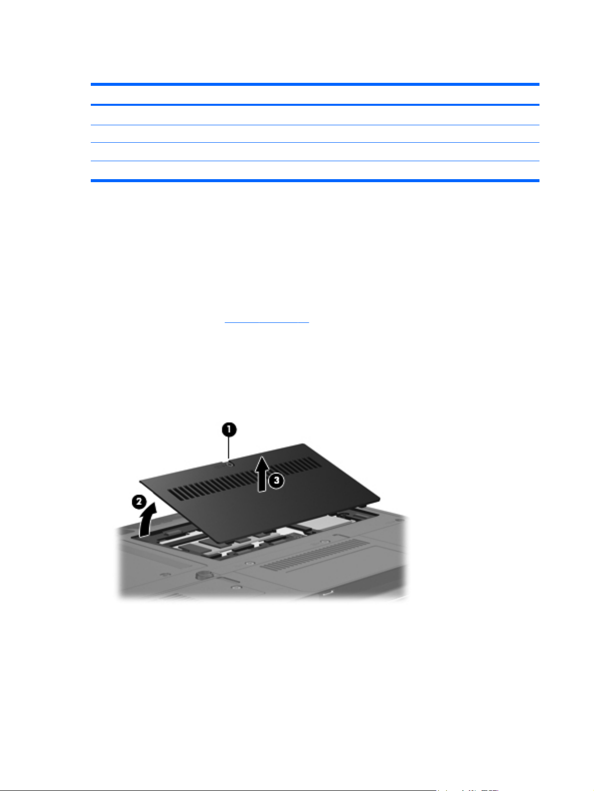
Expansion memory module
Description Spare part number
Memory modules (PC2-6400, 800-MHz, DDR2)
4-GB 492572-001
2-GB 492571-001
1-GB 492570-001
Before removing the memory module, follow these steps:
1. Shut down the computer. If you are unsure whether the computer is off or in Hibernation, turn
the computer on, and then shut it down through the operating system.
2. Disconnect all external devices connected to the computer.
3. Disconnect the power from the computer by first unplugging the power cord from the AC outlet
and then unplugging the AC adapter from the computer.
4. Remove the battery (see
Battery on page 46).
Remove the memory module:
1. Loosen the Phillips PM2.5×6.0 captive screw (1) that secures the memory module compartment
cover to the computer.
2. Lift the front edge of the cover (2), swing it back, and remove the cover (3). The memory module
compartment cover is included in the Plastics Kit, spare part number 492577-001.
3. Spread the retaining tabs (1) on each side of the memory module slot to release the memory
module. (The edge of the module opposite the slot rises away from the computer.)
50 Chapter 4 Removal and replacement procedures
Page 59

4. Remove the memory module (2) by pulling the module away from the slot at an angle.
NOTE: The memory module is designed with a notch (3) to prevent incorrect insertion into the
memory module slot.
Reverse this procedure to install the memory module.
Component replacement procedures 51
Page 60

WLAN module
Description Spare part number
● Intel WiFi Link 5100ABGN (802.11a/b/g/n WLAN module): For use in Antigua & Barbuda,
Argentina, Aruba, the Bahamas, Barbados, Bermuda, Brunei, Canada, the Cayman Islands,
Chile, Colombia, Costa Rica, the Dominican Republic, Ecuador, El Salvador, Guam,
Guatemala, Haiti, Honduras, Hong Kong, India, Indonesia, Malaysia, Mexico, Panama,
Paraguay, Peru, Saudi Arabia, Taiwan, Uruguay, the United States, Venezuela, and Vietnam
● Broadcom 4322AGN WiFi Adapter (802.11a/b/g/n WLAN module): For use in Afghanistan,
Albania, Algeria, Andorra, Angola, Antigua & Barbuda, Argentina, Armenia, Aruba, Australia,
Austria, Azerbaijan, the Bahamas, Bahrain, Bangladesh, Barbados, Belarus, Belgium, Belize,
Benin, Bermuda, Bhutan, Bolivia, Bosnia & Herzegovina Botswana, Brazil, the British Virgin
Islands, Brunei, Bulgaria, Burkina Faso, Burundi, Cambodia, Cameroon, Cape Verde, the
Central African Republic, Chad, Chile, Colombia, Comoros, the Congo, Costa Rica, Croatia,
Cyprus, the Czech Republic, Denmark, Djibouti, Dominica, the Dominican Republic, East
Timor, Ecuador, Egypt, El Salvador, Equitorial Guinea, Eritrea, Estonia, Ethiopia, Fiji, Finland,
France, French Guiana, Gabon, Gambia, Georgia, Germany, Ghana, Gibraltar, Greece,
Grenada, Guadeloupe, Guatemala, Guinea, Guinea-Bissau, Guyana, Haiti, Honduras, Hong
Kong, Hungary, Iceland, India, Indonesia, Ireland, Israel, Italy, the Ivory Coast, Jamaica,
Jordan, Kazakhstan, Kenya, Kiribati, Kuwait, Kyrgyzstan, Laos, Latvia, Lebanon, Lesotho,
Liberia, Liechtenstein, Lithuania, Luxembourg, Macedonia, Madagascar, Malawi, Malaysia,
the Maldives, Mali, Malta, the Marshall Islands, Martinique, Mauritania, Mauritius, Mexico,
Micronesia, Monaco, Mongolia, Montenegro, Morocco, Mozambique, Namibia, Nauru, Nepal,
the Nether Antilles, the Netherlands, New Zealand, Nicaragua, Niger, Nigeria, Norway,
Oman, Palau, Panama, Papua New Guinea, Paraguay, the People's Republic of China, Peru,
the Philippines, Poland, Portugal, Qatar, the Republic of Moldova, Romania, Russia,
Rwanda, Samoa, San Marino, Sao Tome & Principe, Saudi Arabia, Senegal, Serbia, the
Seychelles, Sierra Leone, Singapore, Slovakia, Slovenia, the Solomon Islands, Somalia,
South Africa, South Korea, Spain, Sri Lanka, St. Kitts & Nevis, St. Lucia, St. Vincent and the
Grenadines, Suriname, Swaziland, Sweden, Switzerland, Taiwan, Tajikistan, Tanzania,
Thailand, Togo, Tonga, Trinidad & Tobago, Tunisia, Turkey, Turkmenistan, Tuvalu, Uganda,
Ukraine, the United Arab Emirates, the United Kingdom, Uruguay, Uzbekistan, Vanuatu,
Venezuela, Vietnam, Yemen, Zaire, Zambia, and Zimbabwe
480985-001
487330-002
● Broadcom 4322AGN WiFi Adapter (802.11a/b/g/n WLAN module): For use in the United
States and Canada
● Intel WiFi Link 5100ABGN with AMT (active management technology) (802.11a/b/g/n WLAN
module): For use in the United States and Canada
● Intel WiFi Link 5100ABG (802.11a/b/g WLAN module): For use in the United States and
Canada
● Intel WiFi Link 5100ABG with AMT (active management technology) (802.11a/b/g WLAN
module): For use in the United States and Canada
487330-001
506678-001
482957-001
506680-001
52 Chapter 4 Removal and replacement procedures
Page 61

Description Spare part number
● Broadcom 4312G WiFi Adapter (802.11b/g WLAN module): For use in Afghanistan, Albania,
Algeria, Andorra, Angola, Antigua & Barbuda, Argentina, Armenia, Aruba, Australia, Austria,
Azerbaijan, the Bahamas, Bahrain, Bangladesh, Barbados, Belarus, Belgium, Belize, Benin,
Bermuda, Bhutan, Bolivia, Bosnia & Herzegovina Botswana, Brazil, the British Virgin Islands,
Brunei, Bulgaria, Burkina Faso, Burundi, Cambodia, Cameroon, Cape Verde, the Central
African Republic, Chad, Chile, Colombia, Comoros, the Congo, Costa Rica, Croatia, Cyprus,
the Czech Republic, Denmark, Djibouti, Dominica, the Dominican Republic, East Timor,
Ecuador, Egypt, El Salvador, Equitorial Guinea, Eritrea, Estonia, Ethiopia, Fiji, Finland,
France, French Guiana, Gabon, Gambia, Georgia, Germany, Ghana, Gibraltar, Greece,
Grenada, Guadeloupe, Guatemala, Guinea, Guinea-Bissau, Guyana, Haiti, Honduras, Hong
Kong, Hungary, Iceland, India, Indonesia, Ireland, Israel, Italy, the Ivory Coast, Jamaica,
Jordan, Kazakhstan, Kenya, Kiribati, Kuwait, Kyrgyzstan, Laos, Latvia, Lebanon, Lesotho,
Liberia, Liechtenstein, Lithuania, Luxembourg, Macedonia, Madagascar, Malawi, Malaysia,
the Maldives, Mali, Malta, the Marshall Islands, Martinique, Mauritania, Mauritius, Mexico,
Micronesia, Monaco, Mongolia, Montenegro, Morocco, Mozambique, Namibia, Nauru, Nepal,
the Nether Antilles, the Netherlands, New Zealand, Nicaragua, Niger, Nigeria, Norway,
Oman, Palau, Panama, Papua New Guinea, Paraguay, the People's Republic of China, Peru,
the Philippines, Poland, Portugal, Qatar, the Republic of Moldova, Romania, Russia,
Rwanda, Samoa, San Marino, Sao Tome & Principe, Saudi Arabia, Senegal, Serbia, the
Seychelles, Sierra Leone, Singapore, Slovakia, Slovenia, the Solomon Islands, Somalia,
South Africa, South Korea, Spain, Sri Lanka, St. Kitts & Nevis, St. Lucia, St. Vincent and the
Grenadines, Suriname, Swaziland, Sweden, Switzerland, Taiwan, Tajikistan, Tanzania,
Thailand, Togo, Tonga, Trinidad & Tobago, Tunisia, Turkey, Turkmenistan, Tuvalu, Uganda,
Ukraine, the United Arab Emirates, the United Kingdom, Uruguay, Uzbekistan, Vanuatu,
Venezuela, Vietnam, Yemen, Zaire, Zambia, and Zimbabwe
Broadcom 4312G WiFi Adapter (802.11b/g WLAN module): For use in the United States and
●
Canada
459263-002
459263-001
Before removing the WLAN module, follow these steps:
1. Shut down the computer. If you are unsure whether the computer is off or in Hibernation, turn
the computer on, and then shut it down through the operating system.
2. Disconnect all external devices connected to the computer.
3. Disconnect the power from the computer by first unplugging the power cord from the AC outlet
and then unplugging the AC adapter from the computer.
4. Remove the battery (see
Battery on page 46).
Remove the WLAN module:
1. Loosen the Phillips PM2.5×6.0 captive screw (1) that secures the memory module compartment
cover to the computer.
Component replacement procedures 53
Page 62

2. Lift the front edge of the memory module compartment cover (2), swing it back, and remove the
cover (3). The memory module compartment cover is included in the Plastics Kit, spare part
number 492577-001.
3. Disconnect the WLAN antenna cables (1) from the terminals on the WLAN module.
NOTE: The black WLAN antenna cable is connected to the WLAN module “Main” terminal.
The white WLAN antenna cable is connected to the WLAN module “Aux” terminal.
4. Remove the two Phillips PM2.0×4.0 screws (2) that secure the WLAN module to the computer.
(The edge of the module opposite the slot rises away from the computer.)
5. Remove the WLAN module (3) by pulling the module away from the slot at an angle.
NOTE: WLAN modules are designed with a notch (4) to prevent incorrect insertion.
Reverse this procedure to install the WLAN module.
54 Chapter 4 Removal and replacement procedures
Page 63
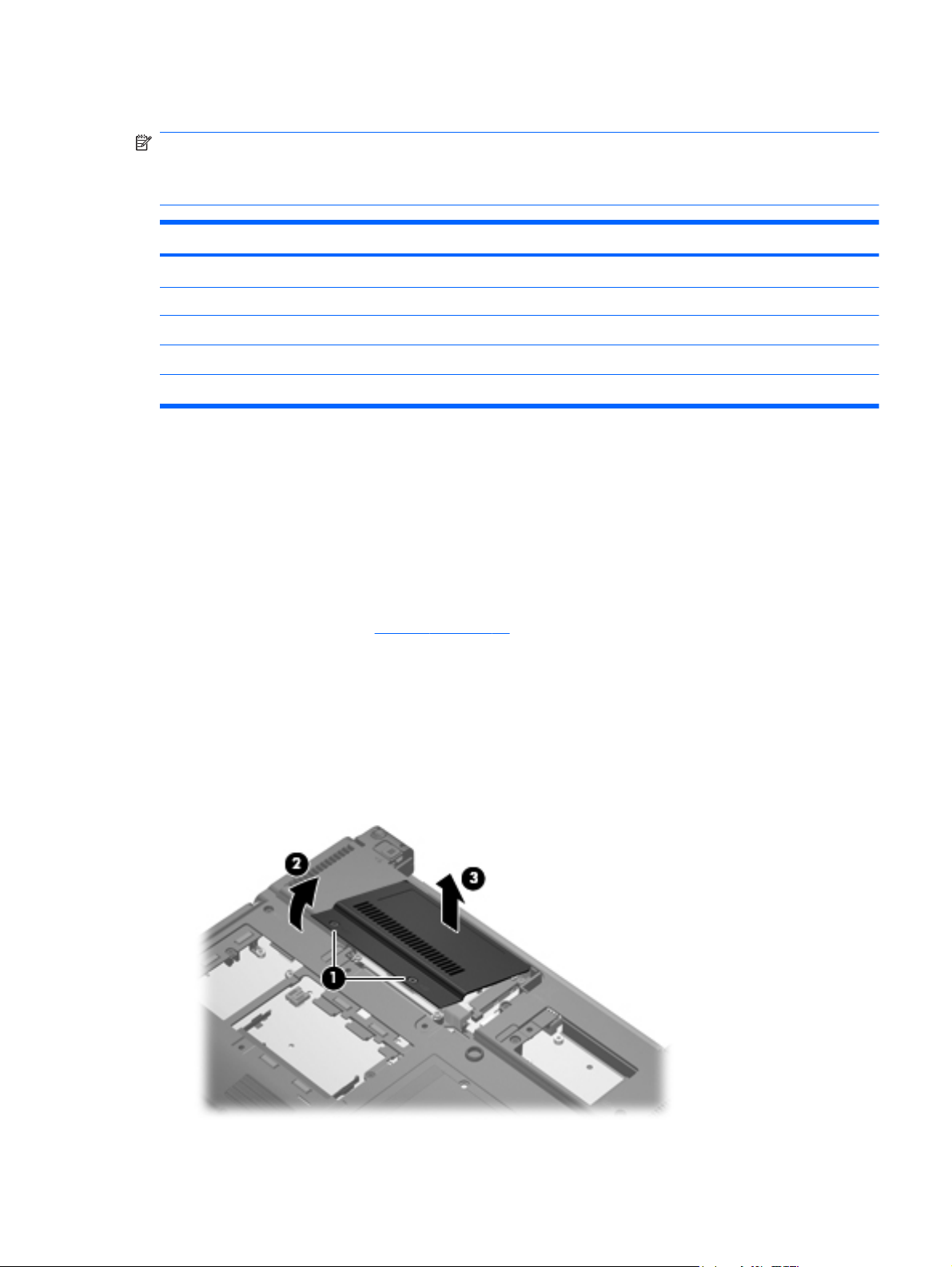
Primary hard drive
NOTE: The 4.57-cm (1.80-inch) primary hard drive must be installed in the hard drive bay.
Installation of this drive in the optical drive bay is not supported.
NOTE: All primary hard drive spare part kits include a hard drive bracket.
Description Spare part number
160-GB, 5400-rpm hard drive 503732-001
120-GB, 5400-rpm hard drive 492560-001
80-GB, 5400-rpm hard drive 492565-001
80-GB, solid-state hard drive 492566-001
Primary hard drive connector board (required for installation of primary hard drive) 495026-001
Before removing the primary hard drive, follow these steps:
1. Shut down the computer. If you are unsure whether the computer is off or in Hibernation, turn
the computer on, and then shut it down through the operating system.
2. Disconnect all external devices connected to the computer.
3. Disconnect the power from the computer by first unplugging the power cord from the AC outlet
and then unplugging the AC adapter from the computer.
4. Remove the battery (see
Battery on page 46).
Remove the primary hard drive:
1. Position the computer with the front toward you.
2. Loosen the two Phillips PM2.5×6.0 captive screws (1) that secure the primary hard drive bay
cover to the computer.
3. Lift the inner side of the primary hard drive bay cover (2), swing it up, and remove the cover (3).
The primary hard drive bay cover is included in the Plastics Kit, spare part number 492577-001.
Component replacement procedures 55
Page 64

4. Loosen the 2 Phillips 2.0×6.0 captive screws (1) that secure the hard drive bracket, and remove
the hard drive bracket (2).
5. Remove the Phillips screw that secures the connector board to the base enclosure(3).
6. Tilt the primary hard drive up toward you (1) to disengage it from the compartment.
7. Grasp the edges of the connector board, and disconnect the hard drive (2) from the connector
board.
8. Remove the hard drive (3).
56 Chapter 4 Removal and replacement procedures
Page 65

9. Pull the edges of the protective rubber gasket out and away from the hard drive (1), and remove
the gasket (2).
10. If it is necessary to replace the primary hard drive connector board, release the ZIF connectors
(1) to which the primary hard drive connector board cable is attached, and disconnect the cable
(2).
11. Remove the primary hard drive connector board (3).
Reverse this procedure to reassemble and install the primary hard drive.
Component replacement procedures 57
Page 66

WWAN module
Description Spare part number
HP un2400 Mobile Broadband Module 483377-002
CAUTION: The WWAN module and the WLAN module are not interchangeable.
CAUTION: To prevent an unresponsive system, replace the wireless module only with a wireless
module authorized for use in the computer by the governmental agency that regulates wireless
devices in your country or region. If you replace the module and then receive a warning message,
remove the module to restore computer functionality, and then contact technical support through Help
and Support.
Before removing the WWAN module, follow these steps:
1. Shut down the computer. If you are unsure whether the computer is off or in Hibernation, turn
the computer on, and then shut it down through the operating system.
2. Disconnect all external devices connected to the computer.
3. Disconnect the power from the computer by first unplugging the power cord from the AC outlet
and then unplugging the AC adapter from the computer.
4. Remove the battery (see
Battery on page 46).
Remove the WWAN module:
1. Loosen the Phillips PM2.5×6.0 captive screw (1) that secures the broadband wireless module
cover to the computer. (The edge of the module opposite the slot rises away from the computer.)
2. Lift the inside edge of the cover and slide out to disengage the tabs (2).
3. Remove the cover (3).
4. Disconnect the WWAN antenna cables (1) from the terminals on the WWAN module.
NOTE: The red WWAN antenna cable is connected to the WWAN module “Main” terminal. The
blue WWAN antenna cable is connected to the WWAN module “Aux” terminal.
58 Chapter 4 Removal and replacement procedures
Page 67

5. Remove the two Phillips PM2.0×4.0 screws that secure the module to the computer (2).
6. Remove the WWAN module (3) by pulling the module away from the slot at an angle.
NOTE: WWAN modules are designed with a notch (4) to prevent incorrect insertion.
Reverse this procedure to install the WWAN module.
Component replacement procedures 59
Page 68

Optical drive
Description Spare part number
Optical drives
DVD-ROM Drive 492558-001
DVD±RW and CD-RW SuperMulti Double-Layer Combo Drive 492559-001
Before removing the optical drive, follow these steps:
1. Shut down the computer. If you are unsure whether the computer is off or in Hibernation, turn
the computer on, and then shut it down through the operating system.
2. Disconnect all external devices connected to the computer.
3. Disconnect the power from the computer by first unplugging the power cord from the AC outlet
and then unplugging the AC adapter from the computer.
4. Remove the battery (see
5. Remove the memory module compartment cover (see
Battery on page 46).
Expansion memory module on page 50).
Remove the optical drive:
1. Position the computer with the right side toward you.
2. Remove the Mylar screw cover (1) that secures the optical drive retention screw. The Mylar
screw cover is available in the Rubber Kit, spare part number 481106-001.
3. Remove the two Torx T8M2.0×5.0 screws (2) that secure the optical drive to the computer.
4. Remove the optical drive (3) from the computer.
5. If it is necessary to replace the optical drive bracket, position the optical drive with the rear
toward you.
6. Remove the two Phillips PM2.0×4.0 screws (1) that secure the optical drive bracket to the optical
drive.
60 Chapter 4 Removal and replacement procedures
Page 69

7. Remove the optical drive bracket (2).
Reverse this procedure to reassemble and install an optical drive.
Component replacement procedures 61
Page 70

Switch cover and keyboard
Description Spare part number
Switch cover (includes display lid switch board and cable) 492556-001
Keyboard with pointing stick (includes keyboard cable and pointing stick cable)
● For use in Brazil 506677-201
For use in the Czech Republic 506677-221
●
● For use in Denmark 506677-081
● For use in Europe 506677-021
For use in Finland and Sweden 506677-B71
●
● For use in France 506677-051
● For use in French Canada 506677-121
For use in Germany 506677-041
●
● For use in Greece 506677-151
● For use in Hungary 506677-211
For use in Iceland 506677-DD1
●
● For use in Israel 506677-BB1
● For use in Italy 506677-061
For use in Japan 506677-291
●
● For use in Latin America 506677-161
● For use in the Netherlands and Europe 506677-A41
For use in Norway 506677-091
●
● For use in Portugal 506677-131
● For use in Russia 506677-251
For use in Saudi Arabia 506677-171
●
● For use in Slovakia 506677-231
● For use in South Korea 506677-AD1
For use in Spain 506677-071
●
● For use in Switzerland 506677-111
● For use in Taiwan 506677-AB1
For use in Thailand 506677-281
●
● For use in Turkey 506677-141
● For use in the United Kingdom 506677-031
For use in the United States 506677-001
●
62 Chapter 4 Removal and replacement procedures
Page 71

Before removing the switch cover and keyboard, follow these steps:
1. Shut down the computer. If you are unsure whether the computer is off or in Hibernation, turn
the computer on, and then shut it down through the operating system.
2. Disconnect all external devices connected to the computer.
3. Disconnect the power from the computer by first unplugging the power cord from the AC outlet
and then unplugging the AC adapter from the computer.
4. Remove the battery (see
5. Remove the WWAN module compartment cover (see
6. Remove the expansion memory module compartment cover (see
Battery on page 46).
WWAN module on page 58).
Expansion memory module
on page 50).
7. Remove the hard drive bay cover (see
Primary hard drive on page 55).
Remove the switch cover and keyboard:
1. Position the computer with the rear panel toward you.
2. Remove the Phillips PM2.5×6.0 screw (1) that secures the switch cover to the computer.
3. Loosen the five Phillips PM2.5×11.0 captive screws (2) that secure the keyboard to the
computer.
4. Turn the computer right-side up, with the front toward you.
5. Open the display as far as possible.
Component replacement procedures 63
Page 72

6. Release the switch cover (1) by sliding it to the right, and then lifting it (2) as far as the LED
board cable and the power button board cable allow.
7. Lift the rear edge of the keyboard and swing it up and forward until it rests upside down on the
palm rest.
8. Release the zero insertion force (ZIF) connector (1) to which the keyboard cable is attached, and
disconnect the keyboard cable (2) from the system board.
64 Chapter 4 Removal and replacement procedures
Page 73

9. Release the ZIF connector (3) to which the pointing stick cable is attached, and disconnect the
pointing stick cable (4) from the system board.
10. Remove the keyboard.
11. Disconnect the LED board cable (1) and the power button board cable (2) from the system
board.
12. Remove the switch cover.
Reverse this procedure to install the switch cover and keyboard.
Component replacement procedures 65
Page 74

RTC battery
NOTE: Removing the RTC battery and leaving it uninstalled for 5 or more minutes causes all
passwords and CMOS settings to be cleared.
Description Spare part number
RTC battery 481089-001
Before removing the RTC battery, follow these steps:
1. Shut down the computer. If you are unsure whether the computer is off or in Hibernation, turn
the computer on, and then shut it down through the operating system.
2. Disconnect all external devices connected to the computer.
3. Disconnect the power from the computer by first unplugging the power cord from the AC outlet
and then unplugging the AC adapter from the computer.
4. Remove the battery (see
5. Release the switch cover and keyboard (see
Battery on page 46).
Switch cover and keyboard on page 62).
6. Use a fingernail or other tool to lift the RTC battery from the socket (1).
7. Remove the RTC battery from the socket on the system board (2).
Reverse this procedure to install the RTC battery.
66 Chapter 4 Removal and replacement procedures
Page 75

Secondary hard drive
NOTE: The 6.35-cm (2.50-inch) secondary hard drive must be installed in the optical drive bay.
Installation of this drive in the hard drive bay is not supported. (This option is not available when the
optical drive is installed.)
Description Spare part number
320-GB, 7200-rpm hard drive 513949-001
250-GB, 5400-rpm hard drive 513948-001
160-GB, 7200-rpm hard drive 492564-001
160-GB, 5400-rpm hard drive 513950-001
120-GB, 5400-rpm hard drive 492561-001
Secondary hard drive cage assembly, includes additional USB port (required for
installation of secondary hard drive
Secondary hard drive connector board (required for installation of secondary hard drive) 495027-001
Secondary hard drive system connector board (required for installation of secondary hard
drive)
492574-001
495028-001
NOTE: The optional secondary hard drive is installed in the optical drive bay, and replaces the
optical drive.
Before removing the secondary hard drive, follow these steps:
1. Shut down the computer. If you are unsure whether the computer is off or in Hibernation, turn
the computer on, and then shut it down through the operating system.
2. Disconnect all external devices connected to the computer.
3. Disconnect the power from the computer by first unplugging the power cord from the AC outlet
and then unplugging the AC adapter from the computer.
4. Remove the battery. (See
5. Remove the switch cover and keyboard. (See
Battery on page 46)
Switch cover and keyboard on page 62)
Remove the secondary hard drive:
1. Close the display, and position the computer upside down, with the right side toward you.
Component replacement procedures 67
Page 76

2. Remove the 5 Mylar screw covers (1), the 4 Phillips screws (2), and the 2 Phillips PM2.0×6.0
screws (3) that secure the secondary hard drive cradle assembly to the computer.
3. Turn the computer right-side up, and open the display as far as possible.
4. Disconnect the secondary hard drive cradle assembly USB cable from the system board.
5. Release the USB cable from all obstructions (1) and tuck the excess cable and connector
securely into the cradle assembly (2).
NOTE: Be sure that the USB connector and cable are completely disconnected from the
system board and secured inside the cradle assembly before you remove the cradle assembly
from the optical drive bay.
68 Chapter 4 Removal and replacement procedures
Page 77
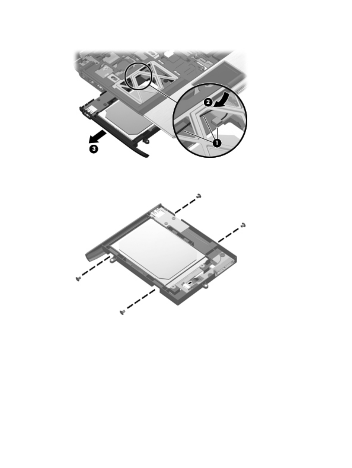
6. Remove the secondary hard drive cradle assembly (3) from the optical drive bay.
7. Remove the four Phillips PM3.0×4.0 secondary hard drive screws that secure the secondary
hard drive to the cradle assembly.
8. Tilt the hard drive up and away from the connector board (1), and disconnect the hard drive from
the connector board (2).
Component replacement procedures 69
Page 78

9. Remove the hard drive from the cradle assembly (3).
10. If it is necessary to replace the secondary hard drive connector board, remove the two Phillips
screws that secure the connector board to the cradle assembly (1).
11. Remove the secondary hard drive connector board (2).
12. If it is necessary to replace the secondary hard drive system connector board, remove the two
Phillips screws that secure the connector board to the cradle assembly (1).
13. Release the ZIF connector (2), and disconnect the cable (3).
70 Chapter 4 Removal and replacement procedures
Page 79

14. Remove the secondary hard drive system connector board (4).
Reverse the above procedure to reassemble and install the secondary hard drive.
Component replacement procedures 71
Page 80

Primary memory module
Description Spare part number
Memory modules (PC2-6400, 800-MHz, DDR2)
4-GB 492572-001
2-GB 492571-001
1-GB 492570-001
Before removing the primary memory module, follow these steps:
1. Shut down the computer. If you are unsure whether the computer is off or in Hibernation, turn
the computer on, and then shut it down through the operating system.
2. Disconnect all external devices connected to the computer.
3. Disconnect the power from the computer by first unplugging the power cord from the AC outlet
and then unplugging the AC adapter from the computer.
4. Remove the battery (see
5. Release the switch cover and keyboard (see
Battery on page 46).
Switch cover and keyboard on page 62).
Remove the memory module:
1. Spread the retaining tabs (1) on each side of the memory module slot to release the memory
module. (The edge of the module opposite the slot rises away from the computer.)
2. Remove the memory module (2) by pulling the module away from the slot at an angle.
NOTE: The memory module is designed with a notch (3) to prevent incorrect insertion into the
memory module slot.
Reverse this procedure to install the memory module.
72 Chapter 4 Removal and replacement procedures
Page 81

Display assembly
Description Spare part number
12.1-inch, WXGA AntiGlare display assembly
With a webcam 492576-001
Without a webcam 492575-001
Display bezel (includes HP logo and computer model number label)
For use with models that include a webcam 495022-001
For use with models that do not include a webcam 495019-001
Display bezel adhesive 497013-001
Display Hinge Kit (includes left and right hinges and brackets) 481098-001
Display panel cable
For use with models that include a webcam 495023-001
For use with models that do not include a webcam 495021-001
Microphone 492573-001
Display enclosure (includes HP logo, wireless antenna transceivers and cables)
With webcam 496490-001
Without webcam 495020-001
Before removing the display assembly, follow these steps:
1. Shut down the computer. If you are unsure whether the computer is off or in Hibernation, turn
the computer on, and then shut it down through the operating system.
2. Disconnect all external devices connected to the computer.
3. Disconnect the power from the computer by first unplugging the power cord from the AC outlet
and then unplugging the AC adapter from the computer.
4. Remove the battery (see
5. Remove the Bluetooth compartment cover (see
6. Remove the memory module compartment cover (see
7. Remove the hard drive bay cover (see
8. Remove the broadband wireless compartment cover (see
9. Remove the switch cover and keyboard (see
Battery on page 46).
Bluetooth module on page 48).
Expansion memory module on page 50).
Primary hard drive on page 55).
WWAN module on page 58).
Switch cover and keyboard on page 62).
Remove the display assembly:
1. Close the computer and turn it upside down, with the rear panel toward you.
2. Disconnect the wireless antenna cables from the WLAN module (1), and feed them down
through the hole (2).
Component replacement procedures 73
Page 82

3. Disconnect the wireless antenna cables from the WWAN module (3), and feed them down
through the hole (4).
4. Turn the computer right side up, and open the display .
5. Thread the WLAN (1) and WWAN (2) cables out through the top cover, and release the cables
from the top cover clips (3).
6. Close the computer and turn the computer upside down, with the rear of the computer toward
you.
74 Chapter 4 Removal and replacement procedures
Page 83

7. Remove the two Mylar screw covers (1) and the four Torx T8M2.0×6.0 screws (2) that secure
the display assembly to the computer.
8. Turn the computer right-side up, with the front toward you.
9. Open the computer.
CAUTION: The display assembly will be unsupported when the following screws are removed.
To prevent damage to the display assembly, support it before removing the screws.
10. Remove the two Torx8 T8M2.5×6.0 screws (one at each hinge) (1) that secure the display
assembly hinges to the computer.
11. Lift the display assembly straight up to remove it (2).
Component replacement procedures 75
Page 84

12. If it is necessary to replace the display bezel, remove the four rubber screw covers (1) and the
four Torx T8M2.5×6.0 screws (2) that secure the display bezel to the display assembly.
NOTE: The rubber screw covers on the display bezel top edge are thicker than the rubber
screw covers on the display bezel bottom edge.
13. Flex the inside edges of the bottom (1), left and right sides (2), and the top (3) of the display
bezel until the bezel disengages from the display enclosure.
14. Remove the display bezel (4).
NOTE: Remove excess adhesive from the bezel and display enclosure when you remove the
bezel, and reapply adhesive before replacing the bezel.
15. If it is necessary to replace the display hinges, remove the two Phillips PM2.5×4.0 screws (1)
that secure the display panel to the display enclosure.
16. Disconnect the display passthrough board and camera passthrough board cables (2).
76 Chapter 4 Removal and replacement procedures
Page 85

17. Remove the display panel (3).
18. Remove the two Phillips PM2.0×4.0 screws (1) that secure each display hinge to the display
panel.
19. Remove the display hinges (2).
20. If it is necessary to replace the display panel cable, turn the display panel upside down, with the
display panel bottom edge toward you.
21. Disconnect the display panel cable from the inverter (1).
22. Disconnect the display panel cable (2) from the display panel.
Component replacement procedures 77
Page 86

23. Remove the display panel cable (3).
24. If it is necessary to replace the microphones (1), remove the microphones from the display
enclosure (2).
Reverse this procedure to reassemble and install the display assembly.
78 Chapter 4 Removal and replacement procedures
Page 87

Top cover
Description Spare part number
Top cover (includes TouchPad board and cable, TouchPad button board and cable, and
TouchPad bracket)
With fingerprint reader 492557-001
Without fingerprint reader 514059-001
Before removing the top cover, follow these steps:
1. Shut down the computer. If you are unsure whether the computer is off or in Hibernation, turn
the computer on, and then shut it down through the operating system.
2. Disconnect all external devices connected to the computer.
3. Disconnect the power from the computer by first unplugging the power cord from the AC outlet
and then unplugging the AC adapter from the computer.
4. Remove the battery (see
Battery on page 46).
5. Remove the following components:
a. Primary hard drive (see
b. Optical drive (see
Primary hard drive on page 55)
Optical drive on page 60) or Secondary hard drive (see Secondary hard
drive on page 67)
c. Switch cover and keyboard (see
d. Display assembly (see
Display assembly on page 73)
Switch cover and keyboard on page 62)
Remove the top cover:
1. Turn the computer upside down, with the front toward you.
Component replacement procedures 79
Page 88

2. Remove the following screw covers and screws:
(1) Four rubber screw covers. The rubber screw covers are included in the Rubber Kit, spare
part number 481106-001.
(2) Six Torx T8M2.5×6.0 screws.
(3) One Phillips PM2.0×5.0 screw.
(4) One Torx T8M2.0×5.0 screw.
3. Turn the computer right-side up, with the front toward you.
4. Disconnect the TouchPad cable (1), and the fingerprint reader board cable (2) from the system
board.
5. Remove the two Torx T8M2.5×6.0 screws (3) and the Phillips PM2.0×6.0 screw (4) that secure
the top cover to the computer.
80 Chapter 4 Removal and replacement procedures
Page 89

6. Lift the rear edge of the top cover (1) and swing it up and forward until it rests at an angle.
7. Lift the front edge of the top cover (2) until it disengages from the base enclosure.
8. Remove the top cover.
Reverse this procedure to install the top cover.
Component replacement procedures 81
Page 90

LED board
Description Spare part number
LED board (includes cable and Mylar cover) 499209-001
Before removing the LED board, follow these steps:
1. Shut down the computer. If you are unsure whether the computer is off or in Hibernation, turn
2. Disconnect all external devices connected to the computer.
3. Disconnect the power from the computer by first unplugging the power cord from the AC outlet
the computer on, and then shut it down through the operating system.
and then unplugging the AC adapter from the computer.
4. Remove the battery (see
Battery on page 46).
5. Remove the following components:
a. Primary hard drive (see
b. Optical drive (see
Primary hard drive on page 55)
Optical drive on page 60) or secondary hard drive (see Secondary hard
drive on page 67)
c. Switch cover and keyboard (see
d. Display assembly (see
e. Top cover (see
Top cover on page 79)
Display assembly on page 73)
Switch cover and keyboard on page 62)
Remove the LED board:
1. Release the ZIF connector to which the LED board cable is connected and disconnect the LED
board cable (1) from the system board.
2. Release the LED board cable (2) from the base enclosure. The LED board cable is attached to
the base enclosure with double-sided tape.
82 Chapter 4 Removal and replacement procedures
Page 91

3. Release the LED board (3) from the clips built into the base enclosure.
4. Remove the LED board and cable.
Reverse the above procedure to install the LED board.
Component replacement procedures 83
Page 92

Speaker
Before removing the speaker, follow these steps:
1. Shut down the computer. If you are unsure whether the computer is off or in Hibernation, turn
2. Disconnect all external devices connected to the computer.
3. Disconnect the power from the computer by first unplugging the power cord from the AC outlet
Description Spare part number
Speaker 481109-001
the computer on, and then shut it down through the operating system.
and then unplugging the AC adapter from the computer.
4. Remove the battery (see
Battery on page 46).
5. Remove the following components:
a. Primary hard drive (see
b. Optical drive (see
Primary hard drive on page 55)
Optical drive on page 60) or Secondary hard drive (see Secondary hard
drive on page 67)
c. Switch cover and keyboard (see
d. Display assembly (see
e. Top cover (see
Top cover on page 79)
Display assembly on page 73)
Switch cover and keyboard on page 62)
Remove the speaker:
1. Disconnect the speaker cable (1) from the system board.
2. Remove the Phillips PM2.0×4.0 screw (2) that secures the speaker to the base enclosure.
3. Remove the speaker (3) from the base enclosure.
Reverse this procedure to install the speaker.
84 Chapter 4 Removal and replacement procedures
Page 93

Bluetooth module cable
NOTE: The Bluetooth module cable is included in the Cable Kit, spare part number 492555-001.
Before removing the system board, follow these steps:
1. Shut down the computer. If you are unsure whether the computer is off or in Hibernation, turn
the computer on, and then shut it down through the operating system.
2. Disconnect all external devices connected to the computer.
3. Disconnect the power from the computer by first unplugging the power cord from the AC outlet
and then unplugging the AC adapter from the computer.
4. Remove the battery (see
5. Remove the following components:
a. Primary hard drive (see
b. WLAN module (see
c. Optical drive (see
drive on page 67)
d. Switch cover and keyboard (see
e. Display assembly (see
f. Top cover (see
Remove the Bluetooth module cable:
1. Release the Bluetooth module cable (1) from the opening in the base enclosure.
2. Disconnect the Bluetooth module cable (2) from the system board.
Battery on page 46).
Primary hard drive on page 55)
WLAN module on page 52)
Optical drive on page 60) or Secondary hard drive (see Secondary hard
Switch cover and keyboard on page 62)
Display assembly on page 73)
Top cover on page 79)
3. Remove the Bluetooth module cable.
Reverse this procedure to install the Bluetooth module cable.
Component replacement procedures 85
Page 94

System board
Description Spare part number
System board (includes processor, replacement thermal material, and replacement thermal
material cleaning kit)
With LV SL9600 processor 513947-001
With LV SL9400 processor 492552-001
With LV SL9300 processor 492551-001
With ULV SU9400 processor 513946-001
With ULV SU9300 processor 492553-001
Before removing the system board, follow these steps:
1. Shut down the computer. If you are unsure whether the computer is off or in Hibernation, turn
the computer on, and then shut it down through the operating system.
2. Disconnect all external devices connected to the computer.
3. Disconnect the power from the computer by first unplugging the power cord from the AC outlet
and then unplugging the AC adapter from the computer.
4. Remove the battery (see
Battery on page 46).
5. Remove the following components:
a. Primary hard drive (see
b. WLAN module (see
c. Optical drive (see
Primary hard drive on page 55)
WLAN module on page 52)
Optical drive on page 60) or Secondary hard drive (see Secondary hard
drive on page 67)
d. Switch cover and keyboard (see
e. Display assembly (see
f. Top cover (see
Top cover on page 79)
Display assembly on page 73)
Switch cover and keyboard on page 62)
When replacing the system board, be sure that the following components are removed from the
defective system board and installed on the replacement system board:
Memory module (see
●
Primary hard drive (see
●
Fan (see
●
Heat sink (see
●
WLAN module (see
●
WWAN module (see
●
Fan on page 92)
Expansion memory module on page 50)
Primary hard drive on page 55)
Heat sink on page 94)
WLAN module on page 52)
WWAN module on page 58)
86 Chapter 4 Removal and replacement procedures
Page 95

Remove the system board:
1. Release the ZIF connector to which the front LED board cable is attached and disconnect the
front LED board cable (1) from the system board.
2. Disconnect the speaker cable (2) from the system board.
3. Remove the three Torx8 T8M2.5×6.0 screws (3) that secure the system board to the base
enclosure.
4. Flex the left side of the base enclosure (1) until the RJ-11 jack and USB ports are clear of the
openings in the base enclosure.
5. Use the optical drive connector (2) to lift the left side of the system board (3) until it rests at an
angle.
6. Remove the system board (4) from the base enclosure by sliding it up and to the left.
Reverse this procedure to install the system board.
Component replacement procedures 87
Page 96

ExpressCard assembly
Description Spare part number
ExpressCard assembly 492567-001
Before removing the PC Card assembly, follow these steps:
1. Shut down the computer. If you are unsure whether the computer is off or in Hibernation, turn
the computer on, and then shut it down through the operating system.
2. Disconnect all external devices connected to the computer.
3. Disconnect the power from the computer by first unplugging the power cord from the AC outlet
and then unplugging the AC adapter from the computer.
4. Remove the battery (see
Battery on page 46).
5. Remove the following components:
a. Primary hard drive (see
b. WLAN module (see
c. Optical drive (see
Primary hard drive on page 55)
WLAN module on page 52)
Optical drive on page 60) or Secondary hard drive (see Secondary hard
drive on page 67)
d. Switch cover and keyboard (see
e. Display assembly (see
f. Top cover (see
Top cover on page 79)
g. System board (see
Display assembly on page 73)
System board on page 86)
Switch cover and keyboard on page 62)
Remove the ExpressCard assembly:
1. Turn the system board upside down, with the front toward you.
2. Remove the two Torx T8M2.0×5.0 screws that secure the ExpressCard assembly to the system
board.
88 Chapter 4 Removal and replacement procedures
Page 97

3. Turn the system board rightside up, with the rear toward you.
4. Remove the ExpressCard assembly.
Reverse this procedure to install the ExpressCard assembly.
Component replacement procedures 89
Page 98

Modem module
Description Spare part number
Modem modules
NOTE: The modem module spare part kits do not include a modem module cable. The modem module cable is included in
the Cable Kit, spare part number 492555-001.
For use in all countries and regions except Australia and New Zealand 461750-001
For use only in Australia and New Zealand 461750-011
Before removing the modem module, follow these steps:
1. Shut down the computer. If you are unsure whether the computer is off or in Hibernation, turn
the computer on, and then shut it down through the operating system.
2. Disconnect all external devices connected to the computer.
3. Disconnect the power from the computer by first unplugging the power cord from the AC outlet
and then unplugging the AC adapter from the computer.
4. Remove the battery (see
Battery on page 46).
5. Remove the following components:
a. Primary hard drive (see
b. WLAN module (see
c. Optical drive (see
Primary hard drive on page 55)
WLAN module on page 52)
Optical drive on page 60) or Secondary hard drive (see Secondary hard
drive on page 67)
d. Switch cover and keyboard (see
e. Display assembly (see
f. Top cover (see
Top cover on page 79)
g. System board (see
Display assembly on page 73)
System board on page 86)
Switch cover and keyboard on page 62)
Remove the modem module:
1. Remove the two Phillips PM2.0×4.0 screws (1) that secure the modem module to the system
board.
2. Lift the modem module up (2) from the system board.
3. Disconnect the modem module cable (3) from the modem module.
90 Chapter 4 Removal and replacement procedures
Page 99

4. Remove the modem module .
Reverse this procedure to install the modem module.
Component replacement procedures 91
Page 100

Fan
Description Spare part number
Fan (includes thermal material) 492568-001
NOTE: To properly ventilate the computer, allow at least a 7.6-cm (3-inch) clearance on the right
side and rear panel of the computer. The computer uses an electric fan for ventilation. The fan is
controlled by a temperature sensor and is designed to turn on automatically when high temperature
conditions exist. These conditions are affected by high external temperatures, system power
consumption, power management/battery conservation configurations, battery fast charging, and
software requirements. Exhaust air is displaced through the ventilation grill located on the left side of
the computer.
Before removing the fan, follow these steps:
1. Shut down the computer. If you are unsure whether the computer is off or in Hibernation, turn
the computer on, and then shut it down through the operating system.
2. Disconnect all external devices connected to the computer.
3. Disconnect the power from the computer by first unplugging the power cord from the AC outlet
and then unplugging the AC adapter from the computer.
4. Remove the battery (see
Battery on page 46).
5. Remove the following components:
a. Primary hard drive (see
b. Optical drive (see
Primary hard drive on page 55)
Optical drive on page 60) or Secondary hard drive (see Secondary hard
drive on page 67)
c. Switch cover and keyboard (see
d. Display assembly (see
e. Top cover (see
Top cover on page 79)
f. System board (see
Display assembly on page 73)
System board on page 86)
Switch cover and keyboard on page 62)
Remove the fan:
1. Turn the system board upside down with the front toward you.
2. Remove the Phillips PM2.5×4.0 screw (1) securing the fan to the system board.
3. Disconnect the cable from the system board (2).
92 Chapter 4 Removal and replacement procedures
 Loading...