

Page 1

58%
14%
8%
20%
1584
4998
325
425
488
2000
18
C4704A/C4703A
HP DesignJet 2500/2000CP Printer
User’s Guide
Page 2

Printed in Europe
All rights are reserved. No part of
this document may be
photocopied, reproduced, or
translated to another lang ua ge
without the prior written con sent
of Hewlett-Packard Company.
3M™ is a registered trademar k of
3M Company.
Adobe™ is a trademark of Adobe
Systems Incor por at ed wh ic h may
be registered in ce rtain
jurisdictions.
Adobe PageMaker™ and Adobe
Photoshop™ are trademarks of
Adobe Systems Incorporated
which may be registered in
certain jurisdictions.
IEEE-1284 compatible, HP-GL,
and
HP-GL/2 are trad em arks of
Hewlett-Packard Company.
Macintosh is a product of Apple
Computer Inc.
Microsoft® and MS- DO S ® are
registered trademarks of
Microsoft Corporatio n.
Microsoft Windows is a
registered trad emark of Micr osoft
Corporation
PANTONE® and P ANTONE
MATCHING SYSTEM® are
licensed trademarks of Pantone.
Inc. PANTONE®
1
Colors
generated by t h e HP DesignJet
2000CP/2500CP printers are
four-color process simulations
and may not match PANTONEidentified solid color standards.
Use current PANTONE Color
Reference Manu als for accurate
color. PANTONE Color
simulations are only obtain ab le
on this product when driven by
qualified Pantone-licensed
software packag es . Contact
Pantone. Inc. for a current list of
qualified licensees.
1.Pantone. Inc.’s check–
standard trademark for
color. ©Pantone. Inc. 1988
PostScript® is a registered
trademark of Adobe Sys tems
Incorporated.
QuickDraw™ is a trademark of
Apple Computer In c.
UNIX® is a register ed tr ade mark
in the United States and other
countries, Ii censed exclusively
through X/Open Company
Limited.
TM
"WingDings
in TrueType®
format is a product of Microsoft
Corporation. WingDings is a
trademark of Micro s o ft
Corporation and TrueType® is a
registered trademark of Apple
Computer, Inc."
Notice
The informatio n co nt aine d in th is
document is subject to change
without notice and should not be
construed as a commitment by
Hewlett-Packard Company.
Hewlett-Packard assumes no
responsibility for an y errors
that may appear in this
document nor does it make
expressed or implied warranty
of any kind with regard to this
material, including, but not
limited to the implied
warranties of merchantability
and fitness for a particular
purpose.
The Hewlett-Packard Company
shall not be liable for incidental
or consequential damages in
connection with, or arising out of
the furnishing. performance. or
use of this document and the
program material which it
describes.
Safety Symbols
CAUTION
The Caution symbol calls
attention to an operating
procedure, practice, or the like,
which, if not correctly performed
The product is marked w ith this
symbol when it is necessary for
you to refer the instruction
manual in order to protect against
damage to the product.
or adhered to, could re sul t in
damage to or destruction of part
or all of the product. Do not
proceed beyond a Caut ion
symbol until the indicate d
conditions are fully understood
and met.
Hazardous voltage sym bol.
WARNING
The Warning symbol calls
attention to a pr oced ure , p ract ic e,
or the like, which, if n ot c orrec tly
performed or adhered to, could
result in personal injury. Do not
proceed beyond a Warning
symbol until the indicate d
conditions are fully understood
and met.
HP DesignJet Printers - Year 2000 Compliance
All HP DesignJet printer prod uc ts in cl uding all
the HP software, hardware, firmware an d
accessories for the HP DesignJet printers are
Year 2000 Compliant. HP DesignJet printers will
function with all the reliabi li ty and quality
associated with Hewlett-Packard as the transition
is made into the 21st century.
============================== ==
“Year 2000 Compliant Products” are products able to accurately process date
data (including, but not limited to, calculating, comparing and sequencin g
dates, from, into and between the twentieth and twenty-first centuries,
including leap year calculations, when used in accordance with its product
documentation, and provided all other products used in combination with the
product properly exchange data with it.
HP has made every effort to ensure the accuracy of out product testing.
However, because each customer’s enviroment is different from HP’s laboratory test enviroment, it is the customer’s responsibility to validate the
Year 2000 readiness of these products in their own enviroment. Therefore,
information about the Year 2000 staus of HP products is provided “as is”
without warranties of any kind.
HP makes no representation or warranty respecting the accuracy or reliability
of information about non-HP products. Such information, if any, was
provided by the manufacturers of those products and customers are urged to
contact the manufacturer directly to verify Year 2000 readiness.
For further information on how HP is preparing for the approaching
millenium visit the HP Year 2000 Program web site:
http://www.hp.com/year2000/
Page 3

C4704-90241 English
User’s Guide
1
HP DesignJet 2500CP/
2000CP Printer
Page 4

Finding Information
Finding Information
This User’s Guide contains:
n A comprehensive explanation of all the printer’s features and specific
information directly associated with the HP DesignJet CP Ink System (Imaging
ink)
n Specific information directly associated with the H P DesignJet CP Ink System
UV (UV Pigmented ink)
n Information on using the Take Up Reel.
The Assem bly Instruct ions contai n:
Step by step instructions for unpacking the printer and installing the Legs.
The Take Up Reel Setup and Assembly Instructions contain
Step by step instructions for installing and setting up the Take Up Reel.
The Setup Guide contains:
n Detailed information on setting up your printer for the first time, including:
– initial installation of the in k system components
– loading media
– connecting your printer to a computer or network
– setting up your printer software
The Quick Reference Guide contains:
n Information that you are most likely to need at the printer on a
day–by–day basis, such as how to navigate through the front-panel menu, load
media, and replace ink systems.
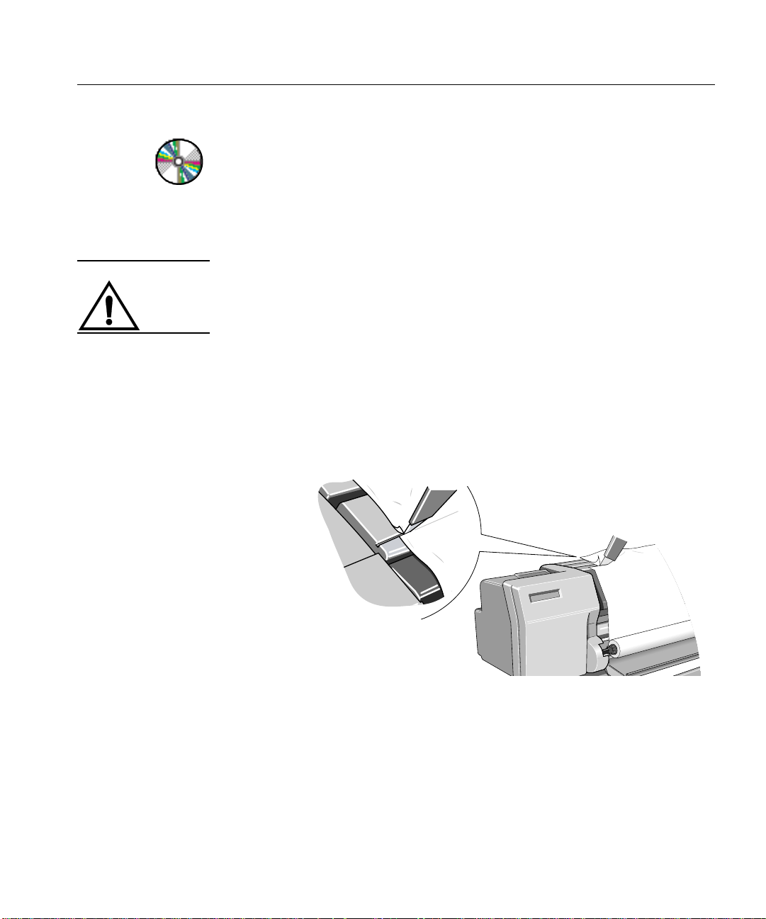
CD-Rom
When this symbol is displayed it indicates that there is video footage available
which gives you more information on the subject. Refer to the CD “Installing and
using HP DesignJet Printers” or “A User’s Introduction” which is only in English.
ii
Page 5

Finding Information
Where to find the most commonly needed information
To find how to … Go to …
Install the printer ÏThe Setup Guide.
Connect the printer ÏThe Setup Guide.
Choose media ÏPage 3-2, Choosing Media in this guide.
Load media ÏPage 3-13, Loading Roll Media in this guide or the quick
reference guide.
Load the Take Up Reel ÏPage 3-19, Loading Media onto the Take Up Reel accessory
Replace ink system components ÏPage 4-11, Removing and Replacing Ink S ystems in this guide.
See the printer’s current configuration ÏPage 8-5, Viewing the Current Configuration of the Front-
Panel Settings.
Turning on the Take up Reel ÏPage 8-12, Tu rning on the Take Up Reel
Make selections in the front-panel menu ÏPage 2-14, Navigating the Menu System.
Clear a media jam ÏPage 11-44, Clearing a Media Jam
Solve image quality problems ÏPage 11-5, Solving Image-Quality Problems
How to Solve Ink System Problems ÏPage 11-31, Solving Ink System Problems
Interpret a front-panel message ÏChapter 12, Front-Panel Messages.
Order accessories ÏPage 13-18, Ordering Accessories
To find any other information
Go to the index at the back of this manual.
iii
Page 6

Table of Contents
Table of Contents
Welcome 1-1
A Five-Minute Guide To Your Printer 1-2
Your Printer’s Main Features 1-2
Connections 1-7
Memory 1-7
Software Applications and Drivers 1-8
Front View of Printer 1-9
Rear View of printer 1-10
Using the Front Panel 2-1
The Front Panel 2-2
Standby Mode 2-6
Printing the Cu rrent Configuration 2-7
Entering the Menu System 2-8
Printing the Menus 2-9
Printing Other Internal Prints 2-12
Navigating the Menu System 2-14
Menu Graphics Used in This Manual 2-15
Navigation Examples 2-16
Selecting the Full Menu Mode 2-16
Changing the Colo r Calibration Settin g in the Image Quality Menu 2-18
Changing the Merg e Setting in HP-GL/ 2 Settings 2-21
Changing Margins 2-24
Changing the Drying Time 2-26
Other Types of Front-Panel Display Information 2-28
Working with Media 3-1
Choosing Media 3-2
Some Important Points about Media Types 3-3
Supported Media Types 3-4
Using the Ink System UV Outsid e 3-5
Laminating the Media after Printing 3-5
Applying the Overlamin ate to a Finished Print 3-5
Installing the Final Print 3-6
Media Types 3-8
HP Commercial Names of Media Types 3-8
iv
Page 7

Table of Contents
Physical Characteristics of Media Types 3-9
Combinations of Media Type and Print Quality 3-10
Using Coated Paper and Heavy Coated Paper with Normal Mode 3-11
Handling Your Media 3-12
Loading Roll Media 3-13
Loading Media onto the Take Up Reel accessory 3-19
Unloading Media from the Take Up Reel accessory 3-26
Removing a Roll from the Printer 3-30
Installing a New Roll into the Prin ter 3-32
Changing the Core Tube on the Take Up Reel 3-35
Loading sheet media 3-39
Unloading Sheet Media 3-42
Compensating for Badly Cut Media 3-27
Adjusting Skew Tolerance 3-27
Drying time (With a Take Up Reel) 3-44
Drying Time (Without a Take Up Reel) 3-46
Working with Ink Systems 4-1
About the Ink System 4-2
The HP DesignJet CP Ink Systems 4-2
Main Features of the HP DesignJet CP Ink System 4-2
What is an Ink System? 4-3
How to Identify the HP DesignJet CP Ink System UV Components 4-4
Identifying the Ink System in the Printer 4-4
When Does the Ink System Refill the Printheads? 4-5
Obtaining Optimum Refill Performance using non-HP media. 4-6
Refilling the Printhea ds from the Front Panel 4-8
How big a print can I make without a refill? 4-8
Monitoring the Ink Level 4-9
When should I Replace an Ink System? 4-10
Removing and Replacing Ink Systems 4-11
Working with multiple Ink Systems 4-12
Handle Ink Systems with Care 4-12
Replace the Ink System 4-13
After replacing the Ink System 4-23
Removing and Storing Partia ll y Used Ink Syste ms 4-24
Handle the Ink Systems with Care 4-24
Storing the I nk System in the HP DesignJet CP Ink System S torage Container 4-25
Removing the Ink System from the HP DesignJet CP Ink System Storage
Container 4-29
v
Page 8

Table of Contents
Controlling the Page Format 5-1
Page Format 5-2
Do You Need to Adjust the Page Size in the Front Panel? 5-4
Adjusting the Page Size in the Front Panel 5-5
Page Size and Clipped Images 5-7
Page Size and Nesting (Roll Media Only) 5-7
Page Size and Accuracy 5-8
Page Size Using the HP DesignJet CP UV Ink System 5-10
Selecting the Ink Emulation Mode 5-11
Adjusting Margins for Roll and Sheet Media 5-12
Margins and Automatic Cutting 5-14
Print Margins using the HP De signJet CP UV Ink System 5-14
Rotating an Image 5-15
Rotating an Image from the Front Panel 5-15
What is Rotated? 5-16
How Does Rotate Interact with Your Software? 5-17
Printing a Mirror Image 5-19
Changing the Scale of a Printed Image 5-20
Controlling the Overall appearance of a Print 6-1
Ways of Controlling the Print’s Appearance 6-2
Changing Pen Widths and Colors Using the Internal Palettes 6-3
To Select a Palette 6-4
Viewing Current Config. Settings 6-5
Viewing the Colors Availab le For a Palette 6-6
To Change the Palette Settings 6-7
Changing the Treatment of Overlapping Lines
(Merge) 6-9
Printing Color Images in Monochrome 6-10
Switching between Color and Monochrome 6-11
Printing Speeds and Print Quality 6-12
Print quality settings 6-14
Changing th e print quality 6-16
Managing Your Prints 7-1
Managing Pages Currently being Printed or Drying 7-2
Cancelling a Page 7-2
Cutting a Page before Drying is Complete
(Roll Media Only) 7-3
vi
Page 9

Pausing while Printing a Series of Pages 7-4
Managing Pages not yet Printed (the Queue) 7-5
What is the Queue? 7-5
Starting to Print a File that is Waiting for a T ime-out 7-7
Identifying a Job in the Queue 7-8
Viewing the Size of a Page in the Queue
(Non-Postscript) 7-8
Prioritizing a Job in the Queue 7-9
Deleting a Job from the Queue 7-9
Making Copies of a Job in the Queue 7-10
Avoiding Media Waste by Nesting Pages 7-11
When Does the Printer Try to Nest Pages? 7-13
Which Pages Qualify for Nesting? 7-13
Which Pages Cannot be Rotated? 7-13
Turning Nesting On or Off and Choosing the Nesting Method 7-14
What Happens to Nesting if You Turn Queueing Off? 7-14
How Long does the Printer Wait for Another File? 7-15
Getting the Best from Nesting (Nesting and Margins) 7-16
Nesting and the Rotate Feature 7-16
Reconfiguring Your Printer 8-1
Table of Contents
Viewing the Current Overall Configuration of the Printer 8-2
Viewing the Current Configuration of the Front-Panel Settings 8-5
To Change the Front-Panel Settings 8-5
Recalibrating the Printer for Accuracy 8-6
When to Recalibrate the Printer 8-6
To Recalibrate the Printer 8-6
To Restore the Factory’s Calibration 8-7
Changing the Graphics Language 8-8
To Change the Graphics Language S etting 8-8
Graphics Language and Networks 8-9
Changing the Interface Settings 8-10
To Change the I/O Time-out Setting 8-10
Upgrading Your Printer with More Memory 8-11
Turning on the Take Up Reel 8-12
Controlling Image Quality 9-1
Selecting the Ink Emulation Mode 9-2
Calibrating the Color Output 9-3
vii
Page 10

Table of Contents
Comparing Color Outp ut between Im aging and UV Ink Systems 9-3
Performing a Image Quality Test 9-4
Servicing the Printheads 9-5
Aligning Printheads 9-5
Refilling Printheads 9-5
Checking Printheads 9-6
Media Test Print 9-7
How to perform the Media Te st Print 9-8
Changing the Print Quality when Media is Already Loaded 9-10
Maintaining Your Printer 10-1
Cleaning the Printer 10-2
Cleaning the Printer Exterior and Inside the Doors 1 0-2
Lens Maintenance 10-3
Replacing the Lens Cover 10-4
Normal Printer Use 10-6
Storing and Moving Your Printer 10-7
Selecting Transport Mode 10-7
Removing the Printheads 10-8
Removing the Printhead Cleaners 10-9
Removing the Ink Cartridges 10-11
Switching off and Disconnecting the Printer 10-13
viii
Troubleshooting 11-1
A Note About Troubleshooting 11-2
Where to Find Help in Solving Problems 11-3
Finding the Source of Your Problem 11-4
Solving Image-Quality Problems 11-5
How to Proceed with the Image Quality Print Diagnosis 11-5
If the Color is Not as Expected 11-6
Some General Information About the Image Quality Test 11-7
Identifying the Printhead Components 11-7
How to Use the Image Quality Print 11-8
Printing the Image Quality Print 11-8
Analyzing the Image Quality Test Results 11-10
Solving the Problems 11-11
No Printing Defects Found in the Image Quality Print 11-22
Solving Color Accuracy problems 11-23
Color Consistency problems 11-23
Page 11

Table of Contents
Configuration 11-24
Media 11-24
Where to Find Additional Information 11-26
If There are Slightly Warped Lines 11-26
If There are Blurred Lines (Ink “Bleeds” from Lines) 11-26
If there is a horizontal line 2 inches (5.5 cms) from the start of your image. 11-26
There are Smears and/or Scratching on Your Printed Media. 11-27
Solving M edia-Handling Problems 11-28
The Front Panel Keeps Indicating that Media Is Misaligned or Incorrectly
Positioned 11-28
Prints Do Not Feed Out Properly From the Printer 11-28
The Automatic Cutter does not Cut Immediately after a Print has Finished 11-28
The Automatic Cutter do es not Work 11-29
The Cutter is Jammed 11-30
A Sheet is Ejected when You Switch On the Printer 11-30
Solving Ink System Problems 11-31
Missing Ink System 11-31
Ink System Error 11-31
Summary of Ink System Defect Messages 11-32
If the Replace Ink System Key does not Work 11-34
If Brand New Printheads have Problems 11-34
If there is a Failure after Refilling Printheads 11-34
Printhead Alignment Errors 11-35
Printhead Checks 11-37
Using the Replace Ink System Key 11-37
Checking Ink Systems 11-38
If You Have Problems Reseating a Printhead 11-41
Cleaning Electrical Contacts 11-42
Clearing a Media Jam 11-44
Solving Communication Problems 11-45
If there is a Problem Communicating between Your Computer and the Printer 11-
45
Solving Problems wi th Image Position or Content 11-46
If the Print is Completely Blank 11-46
If the Output Contains Only a Partial Print 11-46
If the Image is Clipped 11-47
If a Long-Axis Print Is Clipped 11-47
If the Entire Image is in One Quadra nt of the Correct Printing Area 11-48
If the Image Is Unexpectedly Rotated 11-48
If the Print Is a Mirror Image of Your Graphic 11-48
ix
Page 12

Table of Contents
If the Print Is Inaccurate 11-48
If the Print is Distorted or Unin telligible 11-49
If One Image Overlays Another on the Same Sheet 11-49
If Pen Settings Seem to have No Effect 11-49
If the Printer Produces a Black and White Print When You Expected a Color Print
11-49
If the Printer has Printed a Different Print than the One You were Expecting 11-50
Solving Front-Panel Problems 11-51
If the Replace Ink System Key Does Not Work 11-51
If None of the Front-Panel Keys Work 11-51
If Page Format/Rotate does not Work 11-51
If a Display Message will not Clear 11-51
If a “System Error” Message Is Displayed 11-52
If an “Out Of Memory/Data Was Lost” Message Is Displayed 11-52
Problems with the Take Up Reel 11-53
Solving Miscellaneous Problems 11-54
If the Printer does not Print 11-54
If the Printer Seems Too Slow 11-54
If the Printer Waits Too Long to Print a Nest 11-55
If the Bail (Black Metal Bar) does not Lower All the Way 11-55
The Media coming from the Printer is Fed Back into the Printer causing a Media
Jam. 11-55
Getting Help 11-56
What to Do Before You Call 11-56
Front-Panel Messages 12-1
Message Explanations and Actions 12-2
STATUS Messages 12-17
Reference 13-1
Printer Specifications 13-2
Interface Specifications 13-10
Interface Cables 13-11
Regulatory Notices 13-12
Glossary G-1
Index I-1
x
Page 13

Welcome
1
1
A Five-Minute Guide To Your Printer 1-2
Front View of Printer 1-9
Rear View of printer 1-10
1-1
Page 14

Welcome
A Five-Minute Guide To Your Printer
A Five-Minute Guide To Your Printer
Your Printer’s Main Features
Your printer is an E/A0-size inkjet printer designed for printing high-quality, largeformat color or monochrome images. Some major features of the printer are:
n Large capacity ink system
n True 600 dpi print resolution.
n A choice of HP media designed to provide the best image quality with your
printer.
n An easy-to-use front-panel interface with a two-line display, giving you access
to a comprehensive set of printer functions.
n Available as an optional accessory is the Take Up Reel. This enables long
unattended prints
2500CP Only n Built-in Adobe PostScript Level 3 Raster Image Processor.
n Automatic color calibration to improve color consistency betwe en jobs.
n Ink emulation allowing the printer to print jobs intended for devices using
standard pre-press color gamuts.
n PostScript queueing and nesting to reduce media waste.
n Large and very-complex PostScript file printing.
1-2
Page 15

Welcome
A Five-Minute Guide To Your Printer
The Take Up Reel Accessory
Available with your printer as an option is the Take Up Reel. The Take Up Reel
consists of the left and right hand assemblies, sensor assembly, spindle assembly,
core tube and a media weight. As the media is fed out of the printer (1) it travels
down the front of the printer, around the Media Weight (2) and then onto the Core
Tube (3). The Core Tube turns, reeling in the printed media.
C472372
1-3
Page 16

Welcome
A Five-Minute Guide To Your Printer
The HP DesignJet CP Ink Systems
There are two HP DesignJet CP Ink Systems designed together with your HP
DesignJet 2500CP or 2000CP printer.
Both Ink Systems include three-components; printhead, printhead cleaner and ink
cartridge to provide large-capacity ink, unattended printing, ease-of-use, reliability
and low-cost. Plus both Ink S yst ems offer true 600 dpi and new advan ced dit her i ng
algorithms for exceptional image quality prints.
Each 600-dpi thermal inkje t printhead applie s ink dropl ets onto t he media an d has a
reservoir which holds enough ink for several prints. The printer automatically refills
the printhead from the ink cartridge whe never the ink volume in the printhead
reservoir becomes low.
The printer uses the printhead cleaners to clean and maintain the printheads, to
ensure best possible image quality, and to seal the printheads when not in use
ensuring the long life.
You can change Ink Systems as easy as 1—2—3 with the modu la r design. If you d o
change one ink set for another, HP offer an Ink System Storage Container to store
partially used printheads and printhead cleaners.
1-4
Main Features of the HP DesignJet CP Ink System
The HP DesignJet CP Ink System is the ink system that you received with your HP
DesignJet CP printer. It is also referred to as Imaging ink. It is designed to deliver
clear, sharp, brilliant images with precise performance every time.
Main Features of the HP DesignJet CP Ink System UV
The HP DesignJet CP Ink UV can be purchased separatel y from your local Hewlet tPackard dealer. It is also referred to as UV Pigmented ink. The HP DesignJet CP
Ink UV prints bright, colorful, outdoor lightfast signs and posters with a HP
Outdoor Durability Warranty.
The HP DesignJet CP Ink UV is designed to work together with the HP DesignJet
CP printers to create clear prints that are lightfast and durable with lamination, even
outdoor in direct sunlight, for up to one year, guaranteed.
The UV Pigmented inks provide resistance to ultra violet light. Protecting your
prints from fading and enhancing the durability of signs and posters.
Page 17

Welcome
A Five-Minute Guide To Your Printer
Color Calibration (2500CP)
Automatic color calibration improves color consistency between prints. The printer
prints a test target image and measure s the image color with a sensor to generate a
color calibration value that is applied to the P ostScript imaging process.
Ink emulation (2500CP)
Ink emulation lets your printer accept CYMK PostScript files that use printing
industry standard color gamuts, enabling the printer to emulate commercial printing
presses for proofing.
PostScript queueing and nesting (2500CP)
PostScript queueing enables files to be reprint ed quickly . PostS cript nesting reduces
media waste by storing jobs and then positioning them to use the maximum width
of the media roll, reducing your printing costs.
Large/Complex PostScript file printing (2500CP)
The printer uses a built-in hard disk drive as extended memory for PostScript
rendering, enabling the printer to process almost any PostScript file yo u want to
print.
Multiple copies of prints (2500CP)
The built-in hard disk drive allows enhanced print management, enabling the
printer to print multiple copies of an image without re-rendering and nesting of
prints.
Print Resolution
Print resolution can be set to true 600 dots per inch (Best print quality) or 300 dots
per inch (Normal or Fast print quality mode). You can choose between the three
levels of print quality- Best, Normal or Fast - either from your software or from the
printer’s front panel.
1-5
Page 18

Welcome
A Five-Minute Guide To Your Printer
Media
You can print on roll media or sheet media up to EA0-size in width-91cm (36
inches).The following media types are supported for HP DesignJet CP Ink (imaging
ink) which is high image quality for indoor use:
n Coated paper
n Heavyweight coated paper
n High-gloss photo paper
n Semi-gloss photo paper
n Imaging film-Backlit
n Opaque vinyl
For detailed information on Hewlett-Packard media, see pages 3-4 of this manual
and the Media Guide for the HP DesignJe t CP Printers provided with your printer.
The following media types are supported for HP DesignJet CP Ink UV
(UVPigmented Ink)
n HP Heavyweight Coated paper
n Opaque Vinyl
1-6
User Interface
The printer’s front pa nel includes an easy-to-use interface with a two-line display,
giving you access to a comprehensive set of printer functions and to a number of
useful internal pr ints. See Chapter 2, Using the Front Panel, for a short tutorial to
teach you how to navigate through the menus and a description of internal prints.
Standby Mode
The printer has a standby mode where, after 15 minutes of inactivity, the printer
goes into a sleep mode (low-power usage mod e). The pri nter “wak es up” whenever
you press the Standby button on the printer or there is any I/O activity such as
receipt of a file. See page1-9, Front View of Printer, for the switch location and
page 2-6, Standby Mode, for more information about this function.
Page 19

Welcome
A Five-Minute Guide To Your Printer
Connections
2500CP Only The 2500CP printer comes with an HP JetDirect network interface card, for LAN
connections, as well as a parallel interface for a direct connec tion to yo ur computer.
See the Setup Guide for information on connecting your printer to a computer or
network.
2000CP Only Your printer comes with a Modular IO (MIO) slot which can be used to connect a
networking card.
Memory
2500CP Only The 2500CP printer comes with 32MB of memory plus 4 MB of internal printing
memory. You can this expand memory up to a maximum of 68 MB by adding 4MB, 8-MB, 16-MB or 32-MB memory SIMMS. In addition to this memory, the
printer has an internal hard disk drive used as extended memory for PostScript
rendering and print management.
For part numbers see page 13-19, Memory Modules
2000CP Only Your printer comes with 4 MB of m emory plus 4 MB of internal printing memory.
You can expand the memory up to a maximum of 68 MB by adding additional 8MB, 16-MB, and 32-MB memory expansion modules.
For part numbers see page 13-19, Memory Modules
1-7
Page 20

Welcome
A Five-Minute Guide To Your Printer
Software Applications and Drivers
To make sure that your printer prints exactly what you were expecting - in terms of
size, position, orientation, color and quality - use the correct driver for the
combination of your application software and your printer, and make sure that it is
configured correctly.
Many software applications include their own drivers. A set of Software
Application Notes is provided wi th this printer for the most popu lar applications. If
you find your own application in these notes, use the information they contain as a
guide to configuring the software for your printer.
Three types of drivers are supplied with the 2500CP printer:
n HP DesignJet PostScript® drivers for Macintosh® (QuickDraw™)
n HP DesignJet PostScript® drivers for Microsoft® Windows™ applications
n AutoCAD Drivers for DOS and Windows
Two types of drivers are supplied with the 2000CP printer:
n HP-GL/2 Windows Drivers
n AutoCAD Drivers for DOS and Windows
1-8
Some printer functions beh ave differen tly when the print er receives a PostScr ipt file
as opposed to files formatted in other printer languages (HP-GL/2 or RTL).
Throughout this manual, references to “PostScript files” mean files sent to the
printer using the HP DesignJet PostScript driver supplied with the printer and
installed by you on your Macintosh or PC.
If you don't know whether your application sends PostScript files consult your
software documentation.
It is strongly recommended that you install and use the AutoCAD drivers to print
from AutoCAD. More CAD-orientated functionality is provided with these drivers,
they are also faster than HP-GL/2 or PostScript windows drivers.
Page 21

Front View of Printer
Window
Ink Cartridges
(inside)
Roll Cover
Storage S h el f
Media Bin
Welcome
A Five-Minute Guide To Your Printer
Printheads (inside)
Front Panel Display
Front Panel
Printhead Cleaners
(inside)
Standby Switc h
Media Lever
Media-Entry Slot
C4704106
1-9
Page 22

Welcome
A Five-Minute Guide To Your Printer
Rear View of printer
Parallel
Interface
Pocket for Quick
Reference Guide
and Media Knife
Network Interface
Power Switch
Socket for
power cord
Slots for
Upgrades
C4704109
1-10
Page 23

Using the Front Panel
The Front Pane l 2-2
Standby Mode 2-6
Printing the Current Configuration 2-7
Entering the Menu System 2-8
1
2
Printing the Menus 2-9
Printing Other Inte rnal Prints 2-12
Navigating the Menu System 2-14
Menu Graphics Used in This Manual 2-15
Navigation Examples 2-16
Other Types of Front-Panel Display Information 2-28
2-1
Page 24

Using the Front Panel
The Front Panel
The Front Panel
The front panel of the printer is made up of four functional areas as shown below:
Display Section
Form Feed
and CutCancel
Replace
Ink System
Previous
Enter
Pause
Color
Mono
Print Quality KeysAction Keys
Receiving
Print Current
Configuration
(Press both Ke y s)
Best
Normal
Fast
Print Quality
Status
Lights
C4704002
2-2
Page 25

Using the Front Panel
The Front Panel
Display Section The display section of the front panel consists of the two-line display and the four
display keys to its right (Previous, ↑, ↓ and Enter).
Previous
Enter
C4704016
n The display can show two lines of text and is used for displaying:
– menus used to configure the printer.
PAGE FORMAT
Mirroring
Menu Title
Menu Option
C4704007
– and messages.
STATUS
Aligning printheads
C4704034
– These messages may concern printer status, required actions or errors.
n You use the display keys to navigate the menu system and select menu options.
You also use the display keys to respond to messages. see chapter 12, Front-
Panel Messages, for detailed descriptions for error and status messages.
Later sections of this chapter give det ailed inst ructio ns for using the di splay keys to
navigate the menu system and select menu options, as well as other uses of the
display keys.
2-3
Page 26

Using the Front Panel
The Front Panel
Action Keys The action keys let you:
n cancel the current printer operation (Cancel).
n advance and cut media (Form Feed and Cut).
n replace ink system components (Replace Ink System).
n pause the printer (Pause).
Form Feed
and CutCancel
Action Keys
Replace
Ink System Pause
C470432a
dddddddy
See chapter 7, Managing Your Prints, for information on the use of these keys.
Print Quality Keys Use the print quality keys to select whether to print in color or monochrome (black
and grayscale) and to select the print quality you want. See chapter 6, Controlling
the Overall appearance of a Print, for information on the use of these keys.
Best
Color
Mono
Print Quality keys
Normal
Fast
C4704033
2-4
Page 27

Using the Front Panel
The Front Panel
Status Lights The status lights provide status information about the current configuration and
state of the printer. These lights are described later in this manual
Receiving
Best
Pause
Color
Mono
Normal
Fast
Print Quality
Status Lights
C4704031
NOTE In most cases, settings in your application software or printer driver override
any settings you make on the front panel of the printer.
2-5
Page 28

Using the Front Panel
Standby Mode
Standby Mode
The printer has a standby mode where, after a period of inactivity, the printer goes
into a sleep mode (low-power usage mode). This is indicated by the front panel
display and status indicators turning off. The indicator light on the Standby switch
is on when the printer is in standby mode. The printer “wakes up” whenever you
press the Standb y switch on the print er or there is any I/O activ ity such as recei pt of
a file.
Standby switch
C4704131a
You can manually place the printer in standby mode by pressing the Standby
switch when the printer is in normal operating mode. When you manually put the
printer in standby mo de, it will not “wake up” until you press the switch again.
n Use the Standby switch to turn the printer off and on, rather t han the Power
switch on the back of the printer.
n Use the Power Switch only when you need to isolate the printer from t he po wer
source, such as, when you are disconnecting or connecting cables, or upgrading
memory.
NOTE To re-initialize the printer, pre ss and hold the Standby switch for three or more
seconds.
2-6
Page 29

Printing the Current Configuration
The display section is used for setti ng the pr i nte r’s configuration. You can print out
a report showing the printer’s current configuration by following the steps below.
1 Make sure that media is loaded. See page 3-13, Lo adi ng Rol l Media, for loading
information.
2 Press the ↑ and ↓ keys simultaneously to print the Current Configuration.
Previous
Using the Front Panel
Printing the Current Configuration
STATUS
Ready
Next
Press These Two
Keys Simultaneously
C4704019
The current configuration print fits on an A4 or US letter-size sheet. Keep this print
for later reference.
2-7
Page 30

Using the Front Panel
Entering the Menu System
Entering the Menu System
1 Make sure a status screen is displayed, as shown in the example below:
STATUS
Ready
2 Press the Enter key.
Either the SHORT MENUS screen
C4704034
SHORT MENUS
Queueing & Nesting
C4704008
Only menus shaded yellow
in front-panel menus print
are accessible in Short Menus
mode. (Shaded gray if printing
in black only).
or the FULL MENUS screen:
FULL MENUS
All menus are accessible.
Queueing & Nesting
C4704008
is displayed, with the Queueing & Nesting option shown.
NOTE You may not be able to access the menu system immedi ately, if the current task
overrides it. If this happens, wait until the task is completed and try again.
2-8
Page 31

Using the Front Panel
Printing the Menus
Printing the Menus
You can see the complete menu structure available on the printer by printing the
Front-Panel Menus print. To help understand the menu structure and its navigation,
print it now:
NOTE The Menus print is printed in the size specified in the Page Format → Size settings
in the front panel. However if sheet media is loaded it will automatically shrink
to fit. Make sure this setting specifies the size you want before printing.
1 Make sure that media is loaded. See page 3-13, Lo adi ng Rol l Media, for loading
information.
2 On the front-panel display, go to
Internal prints, as shown below.
3 Print the menu structure by selecting t he Menu option from the
as follows:
STATUS
Ready
C4704034
a Press Enter.
Note: Your front-panel display may show
SHORT MENUS
Queueing & Nesting
b Press ↓ until
SHORT MENUS
SHORT MENUS
s
Internal prints
C4704034
Internal prints is displayed.
C4704034
FULL MENUS, not SHORT MENUS, depending
on your printer settings. You can print the
internal prints in either mode.
Internal prints menu,
2-9
Page 32

Using the Front Panel
Printing the Menus
c Press Enter.
d Press ↓ or ↑ until
Menu is displayed.
INTERNAL PRINTS
Menu
C4704034
e Press Enter.
The printer prints a menu tree of the entire front-panel menu structure. The
Receiving light flashes while the file is being processed, and then the printer starts
printing.
2500CP Only Look at the Front-Panel Menus print. It shows the full menu structure. Here is a
sample section of it concerned with image quality:
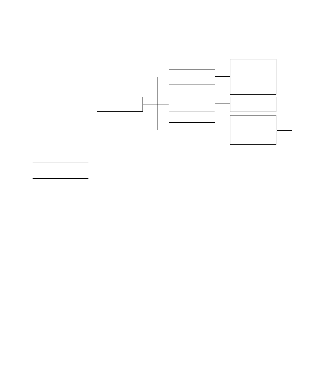
There are six columns:
1 contains the highest
level menu options.
6 contains the lowest
level menu options.
123456
C4704039
2-10
Row associated with
first level menu
(Image Quality).
Area expanded for use
in the navigation example
in this chapter .
Page 33

Using the Front Panel
Printing the Menus
2000CP Only Look at the Front-Panel Menus print. It shows the full menu structure. Here is a
sample section of it (concerned with pen settings):
There are six columns:
1 contains the highest
level menu options.
6 contains the lowest
level menu options.
Row associated with
first level menu
(HP-GL/2).
123456
C4704005
Area expanded for use
in the navigation exa mp le
in this chapter.
2-11
Page 34

Using the Front Panel
Printing Other Internal Prints
Printing Other Internal Prints
In addition to the current confi gurati on print and menu pr int, there are several othe r
internal prints availab le in the printer. The internal prints are listed belo w:
2500CP Only PostScript demo
Demonstrates the image quality capabilities of the printer.
PostScript config
The PostScript Configuration print shows the current configuration status of the
printer’s PostScript features.
PostScript fonts
The Fonts print shows all resident Post Script fonts (inter nal and downloaded) wi th a
printed sample of each font.
2-12
HP-GL/2 config
The HP-GL/2 Configuration print shows the current settings for the printer’s HPGL/2 features.
Usage report
The Printer Usage Information print shows the status of the printer’s usage
counters. This information includes the total nu m ber of prints, number of prints b y
media size, number of prints by media type, number of prints per print mode, and
total amount of ink used per color. The counts in this report are estimates.
Image quality print
The Image Quality print can be us ed to help di agnose whethe r the pri nter has imag e
quality problems, and if problems exist, help determine the cause of image quality
problems see chapter 11, Troubleshooting, for more information about this print.
Page 35

2500CP Only
Using the Front Panel
Printing Other Internal Prints
Service print
The Service print provides information needed for printer servicing, such as the
current configuration, operating conditions (temperature and humidity), ink levels,
and other statistics about printer usage.
n Menu
The Menu print shows the complete menu structure available on the printer to help
you in locating menu options in the front panel.
HP-GL/2 pa lette
The HP-GL/2 Palette print shows the color or grayscale definitions in the currentlyselected color palette.
Where to Find Internal Prints
The following internal prints are located under the Internal Prints menu:
n PostScript demo
n PostScript config
n PostScript fonts
n HP-GL/2 config
n Usage report print
n Menu print
n HP-GL/2 Palette print
The following internal prints are located under the
Utilities menu:
n Image Quality print
n Service print
Service Tests option in the
2-13
Page 36

Using the Front Panel
Navigating the Menu System
Navigating the Menu System
Once in the first-level menu, you can navigate the menu system using the display
keys.
Press Previous to display the previous menu level,
without changing any menu selections (equivalent
to moving left [ ←]
Menus print).
Press ↑ to scroll up, or ↓ to scroll down
through the options in a menu (equival e nt
to moving up [↑] or down [↓] a column
in the Front-Panel Menus print).
The option list is continuous, allowing you
to move from the bottom to the to the top
by pressing ↓ or from the top to the bottom
by pressing ↑.
1
one column in the Front-Panel
Previous
Enter
Press Enter to:
a. select an option and move to the next menu level,
when in the menu system (equivalent to moving one
column to the right [→] in the Front-Panel Menus print).
b. Change the printer’s configuration to the displayed choice
to the configuration, that is, selecting an option from the
the lowest level menu [↵].
1
The colored arrows ↑↓← →↵, shown in square brackets above,
are used to repres ent pressing the rel ev a nt keys once,
in the following navigation example.
C4704006
NOTE A → character in a menu option box indicates that another level of menu is
available.
2-14
Page 37

Menu Graphics Used in This Manual
At the end of this chapter, there are some examples of navigating the menu system,
showing all the menu displays available. In the rest of this manual, a menu graphic
is displayed in the left margin when y ou need to use the menu system. This menu
graphic gives a concise explanation of how to navigate to the exact place.
The graphics look similar to this, but further levels may be shown:
Using the Front Panel
Menu Graphics Used in This Manual
First level selection
Represents pressi ng Enter key
Menu mode required,
and other useful information
Second level
selection
Full menu mode
Default: 0
Affects next file sent
Stays after power off
C4704018
Currently selected options are displayed with a * in the fro nt-panel display.
2-15
Page 38

Using the Front Panel
Navigation Examples
Navigation Examples
Use the following examples to practice navigating the menu system. All examples
assume that you have entered the menu system from the STATUS screen shown
below.
Ready
Selecting the Full Menu Mode
u Make sure the STATUS display level is shown on the front panel:
Ready
STATUS
C4704034
STATUS
C4704034
2-16
1 Press Enter.
SHORT MENUS
Queueing & Nesting
2 Press ↓ or ↑ until
SHORT MENUS
Utilities
3 Press Enter.
UTILITIES
Menu mode=Short
C4704008
Utilities is displayed.
C4704034
→
C4704034
If FULL MENUS is displayed
instead of SHORT MENUS,
press the Previous key and
skip the following steps.
Page 39

4 Press Enter.
MENU MODE
Short*
C4704034
Using the Front Panel
Navigation Examples
5 Press
↓.
MENU MODE
Full
C4704034
6 Press Enter.
UTILITIES
Menu mode=Full →
C4704034
7 Press Previous.
FULL MENUS
Utilities
→
C4704034
8 Press Previous again to return to the
ST ATUS
Ready
ST ATUS screen in the front-panel display.
C4704034
2-17
Page 40

Using the Front Panel
Navigation Examples
2500CP Only
Changing the Color Calibration Setting in the Image Quality Menu
In this example, you will change the
Color Calibration setting in the Image Quality
menu. The arrows on the excerpt from the Front-Pa nel Menus print on page 2-20
correspond to the numbered instructions. From the previous example, you should
now have the STATUS screen displayed on the front panel, with
FULL MENUS
mode selected.
STATUS
Ready
C4704034
1 Press the Enter key to enter the front-panel menu. You are now at the first level
shown in the menu print.
FULL MENUS
Queueing & Nesting
C4704034
2 Press the
↓ key until IMAGE QUALITY is displayed.
FULL MENUS
Image quality
→
C4704034
2-18
3 Press the Enter key to select the option and move t o the
second-level menu. The
Ink emul. option is displayed.
IMAGE QUALITY
Ink emul.=Euroscale→
C4704034
4 Press the
↓ key once to display the Color calibration option.
IMAGE QUALITY
Color calib.=On
→
C4704034
IMAGE QUALITY settings
Page 41

Using the Front Panel
Navigation Examples
5 Press the Enter key to select the option and move to the Co lor calibration third-level
menu. The option currently selected is displayed with a *.
COLOR CALIBRATION
On*
C4704034
6 Change the displayed option by pressing the
↓ or the ↑ key.
COLOR CALIBRATION
Off
C4704034
7 Press the Enter key to set
You will be returned to the
COLOR CALIBRATION to the new dis played setting.
IMAGE QUALITY second-level menu.
IMAGE QUALITY
Color calib.=Off
→
C4704034
8 To exit the menu system, press the Previous key twice.
STATUS
Ready
C4704034
2-19
Page 42

Using the Front Panel
Navigation Examples
If you now reenter the menu system and repeat steps 1 to 4, you will see the option
that you selected displayed with a *.
EuroScale*
4
→
TOYO
Enhanced
Native
SWOP
On*
5↑↓6
Now
Off
↵
1
↓
↓
FULL MENUS
Image quality
8
←
2
→
Ink emul.=
3
↓
→
7
←
Color Calib.=
→
Printhead service=
Check=Frequency
Refill Now
Align Now
→
C4704040
NOTE A → character in a menu option box indicates that a lower level of menu is
available.
2-20
Page 43

Using the Front Panel
Navigation Examples
Changing the Merge Setting in HP-GL/2 Settings
In this example, you will change the Merge setting in the HP-GL/2 Settings. The
arrows on the excerpt of the Front-Panel Menus print on the next page correspond
to the numbered instructions. You should now have the STATUS screen displayed
on the front panel, with FULL MENUS mode selected.
STATUS
Ready
C4704034
1 Press the Enter key to enter the front-panel menu. You are now at the first level
shown in the menu print.
FULL MENUS
Queueing & Nesting
C4704034
2 Press the
↓ key until HP-GL/2 settings is displayed.
FULL MENUS
HP-GL/2 settings
→
C4704034
3 Press the Enter key to select the option and move to the
level menu. The
Palette option is displayed.
HP-GL/2
Palette=Software
4 Press the
↓ key once to display the Merge option.
→
C4704034
HP-GL/2
Merge=Off
→
C4704034
HP-GL/2 settings second-
2-21
Page 44

Using the Front Panel
Navigation Examples
5 Press the Enter key to select the option and move to the Merge third-level menu.
The option currently selected is displayed with a *
MERGE
Off*
C4704034
6 Change the displayed option by pressing the
↓ or the ↑ key.
MERGE
On
C4704034
7 Press the Enter key to set
returned to the
Merge second-level menu.
Merge equal to the new displayed value. You will be
HP-GL/2
Merge=On
→
C4704034
8 To exit the menu system, press the Previous key twice.
STATUS
Ready
C4704034
2-22
Page 45
Using the Front Panel
Navigation Examples
If you now reenter the menu system and repeat steps 1 to 4, you will see the option
that you selected displayed with a *.
1
↓
↓
↓
↓
↓
↓
↓
FULL MENUS
HP-GL/2 Settings
8
←
2
Palette=
→
3
↓
→
Merge=
→
4
←
Define Palette=
4
→
Software*
Palette A
Palette B
Factory
Off*
5↑↓6
On
Palette A
Palette B
Factory
↵
C4704009
NOTE A → character in a menu option box indicates that another level of menu is
available.
2-23
Page 46

Using the Front Panel
Navigation Examples
u Make sure the STATUS display level is shown on the front panel:
Changing Margins
This example shows how to adjust the page margins.
STATUS
Ready
C4704034
1 Enter the menu system by pressing the Enter key.
FULL MENUS
Queueing & Nesting
C4704034
Either the
SHORT MENUS screen or t he FULL MENUS scre en is d ispla yed wi th th e
Queueing & Nesting option. If necessary, see page 2-16, Selecting the Full Menu
Mode, to change to full menu mode.
2 Press the ↑ key or the ↓ key until the
Page Format menu is displayed.
FULL MENUS
Page format
→
C4704034
3 Press the Enter key.
PAGE FORMAT
Size=Software
4 Press the ↑ key, or the ↓ key until the
→
C4704034
Margins option is displayed.
PAGE FORMAT
Margins=Extended
C4704034
2-24
Page 47

Using the Front Panel
Navigation Examples
5 Press the Enter key to display the MARGINS menu.
MARGINS
Extended*
C4704034
6 Use the ↑ and ↓ keys to display the available options and, when the desired option
is displayed, press the Enter key to select it as the setting for
Margins.
7 To exit the menu system, press the Previous key twice.
STATUS
Ready
C4704034
2-25
Page 48

Using the Front Panel
Navigation Examples
u Make sure the
Changing the Drying Time
This example adjusts the drying time, a setting used to suit different environmental
conditions, in the
this example.
Ready
1 Press the Enter key to enter the menu system.
FULL MENUS
Queueing & Nesting
DRYING TIME menu. The printer must be in full menu mode for
STATUS display level is shown on the front panel.:
STATUS
C4704034
C4704034
Either the
SHORT MENUS screen or t he FULL MENUS scre en is d ispla yed wi th th e
Queueing & Nesting option. If necessary, see page 2-16, Selecting the Full Menu
Mode, to change to Full Menu mode.
2 Press the ↑ key or the ↓ key until the
Device Setup menu is displayed.
FULL MENUS
Device Setup
→
C4704034
3 Press the Enter key.
DEVICE SETUP
Lang=Automatic
4 Press the ↑ key or the ↓ key until
→
C4704034
DRYING TIME is displayed.
DEVICE SETUP
Drying time=Automatic
→
C4704034
2-26
Page 49

Using the Front Panel
Navigation Examples
5 Press the Enter key to display the DRYING TIME menu.
DRYING TIME
Automatic*
C4704034
6 Use the ↑ and ↓ keys to display the available options and, when the desired option
is displayed, press the Enter key to select it as the setting for Drying time.
7 To exit the menu system, press the Previous key twice.
STATUS
Ready
C4704034
2-27
Page 50

Using the Front Panel
FULL MENUS
Ink level
Full menu mode
Other Types of Front-Panel Display Information
Other Types of Front-Panel Display Information
Other types of messages are also displayed in the front panel, such as those
displayed for selecting media type during media loading:
SELECT MEDIA
Coated Paper
C4704034
or the amount of ink remaining:
Cyan
Yel
Mgnta
Black
C4704041
There are other selection menus which are not part of the main menu system. These
behave in the same way as th e main menus. You scroll through the options u sing t he
↑
and ↓ keys and select a displayed option using the Enter key.
2-28
Page 51

Working with Media
Choosing Media 3-2
Using the Ink System UV Outside 3-5
Handling Your Media 3-12
Loading Roll Media 3-13
1
3
Loading Media onto the Take Up Reel accessory 3-19
Unloading Media from the Take Up Reel accessory 3-26
Removing a Roll from the Printer 3-30
Installing a New Roll into the Printer 3-32
Changing the Core Tube on the Take Up Reel Accessory 3-35
Loading sheet media 3-39
Unloading Sheet Media 3-42
Drying time (With a Take Up Reel) 3-44
Drying Time (Without a Take Up Reel) 3-46
3-1
Page 52

Working with Media
Choosing Media
Choosing Media
Your printer supports several types of media. Choosing the best media type fo r your
needs is an essential step in ensuring good image quality. For best printing results,
use only genuine He wlett-Packard media, whose reliability and pe rformance have
been developed and thoroughly tested. All HP printing components (printer, ink
system, and media) have been designed to work together to give trouble-free
performance and optimal image quality.
For detailed in formation on Hewlett- Packard media, see pag e 3-4, S upported Med ia
Types, and the HP DesignJet Papers and Films catalog supplied with the printer.
HP has tested some media products developed by a non-HP manufacturer. These
tested products are approved by HP as compatible with this printer.
Some non-endorsed media products are listed in the Media Guide for the HP
DesignJet CP Printers provided with your printer. HP has not tested these media
products to ensure their performance or quality.
If you choose to pri nt on a non- endorsed media it is r ecommended that you per form
the Media Test Print see page 9-7, Media T est Pri nt .
CAUTION Use of non-endorsed coated papers when printing with high ink volume may
saturate the coated paper and could result in serious printhead damage.
CAUTION For the Outdoor Durability Warranty, with the Ink System UV you must
always print on the compatible 3M Opaq ue V inyl medi a. Also you must use 3M
Overlaminate film to maintain the print’s luster, depth and quality.
3-2
Page 53

Working with Media
Choosing Media
Some Important Points about Media Types
n This printer supports many media types. However, the quality of some images
may be reduced if you do not use HP media.
n Whenever you load a roll or a sheet, the printer’s front-panel display prompts
you to specify the media type you are loading. It is absolutely essentia l to specify
this correctly for good image quality. The table on page 3-4, Supported Media
Types, gives you all the information yo u need. If med ia is already l oaded and you
are unsure which media type was specified, go to Utilities / Statistics in the
front-panel menu. See page 8-2, Viewing the Current Overall Configuration of
the printer.
n Make sure the appropriate print-quality setting (Best, Normal or Fast) is
selected. You can set the print quality either from your software or from the
printer’s front panel (software driver settings override any print-quality settings
made on the front panel). The combination of media type and print-quality
settings tells the printer how to place the ink on the media - for example, the ink
density, dithering method, and number of passes of the printheads. For more
details, see the table on page 3-10, Combinations of Media Type and Print
Quality.
n Included with this printer is an HP DesignJet Papers and Films catalog which
gives ordering details for Hewlett-Packard med ia supplies. To get the latest
version of this document, contact your local HP Sales and Support office.
NOTE If you are using a third-party Raster Image Processor (RIP) to print with your
printer, the above points may not apply. In this case, consult your RIP vendor
for advice on media and the best settings for your requirements.
3-3
Page 54

Working with Media
Choosing Media
Supported Media Types
Your printer supports several types of media The supported types and their most
common uses are shown in the table below.
The media you choose will de pend on t he ink system you have installed t hat i s, UV
inks or imaging inks.
Media Type on the FrontPanel Display
Coated Paper
High Gloss Photo Paper
Semi Gloss Photo Paper
Imaging Film-Bac klit
Opaque Vinyl
HP Heavyweight Coated
Paper
3M Changeable Opaque
Imaging Media
NOTE:HP Heavyweight Coated Paper is the only media that is compatible with both
the
Description
A specially coated wood-pulp based paper for inexpensive high-quality
color graphics and photographic image prints.
A white Photographic paper with a high -gloss finish for high quality
prints.
A white Photographic paper with a semi-gloss finish for high quality
prints.
A clear polyester film for backlit viewing of images.
Adhesive-backed white opaque vinyl.
A specially coated heavyweight based paper for high quality color
graphics which when combined with the HP DesignJet CP Ink System
UV provide s enhanced light fastness for indoor and outdoor use.
A flexible white opaque film with removable pressure-sensitive adhesive
backing for outdoor use. It is outstanding for outdoor signs, posters and
banners. When printing with this media use the Best print mode.
HP DesignJet CP Ink System and the HP DesignJet CP Ink System UV.
3-4
NOTE:To order the above media types see page 3-8, HP Commercial Names of
Media Types and the pamphlet Media Guide for the HP DesignJet printers.
From time to time, new media types may become available. For up-to-date
information, please contact your HP dealer or local HP Sales and Support Office.
Page 55

Working with Media
Using the Ink System UV Outside
Using the Ink System UV Outside
Laminating the Media after Printing
After you have printed a file using the HP DesignJet CP Ink System UV on 3M™
Changeable Opaque Imaging Media 8522CP and before displaying the print
outdoors, it must b e l ami nat ed with one of the 3M overlaminates (see Table below).
The use of the overlaminate is essential for outdoor use to provide resistance to
water, scratches and tears and to maintain the print’s luster, depth and quality.
Applying the Overlaminate to a Finished Print
NOTE These guidelines provide a general process for laminating prints to help you
maintain consistent results and best quality. The laminating process may vary,
depending on the laminat i ng equi pment that you are usi ng. Always refe r to t he
manufacturer’s documentation for safe operation and additional information.
Before applying the lamin ate to your finished print, make sure it is completely d ry.
The print will feel almost dr y immediatel y after printi ng, but if you are prin ting i n a
particularly cold or humid en vironment, the dryi ng time ma y be longe r than nor mal.
For these situations wait 15 to 30 minutes before applying the overlaminate.
The 3M overlaminates are not heat-activated adhesives; however, heat can be used
to improve the adhesive flow. The temperature should not exceed 68° C (180° F).
The recommended laminator pressure is a minimum of 15 psi , an d must not exce ed
75 psi.
Overlaminate Type Description
3M Lustre Protective Finish
3M Matte Protective Finish
3M High-Gloss Protective
Finish
2mm vinyl overlaminate with pressure sensitive adhesive for outdo or
use.
2mm vinyl overlaminate with pressure sensitive adhesive for outdo or
use.
2mm vinyl overlaminate with pressure sensitive adhesive for outdo or
use.
3-5
Page 56

Working with Media
Using the Ink System UV Outside
Installing the Final Print
Recommendations to Follow When Installing the Final Print
Follow these recommendations when the final print is to be displayed outdoors:
n Installation temperatures
Final graphic installation temperature should range between 28° F and 110°F.
Final graphic removal temperature should range between 28° F and 110°F.
n Installation surfaces
The print must only be installed on flat, vertical surfaces. It is not recommend ed
to install the final prin t over rivets or corrugations.
The surface should not be susceptible to fuel spillage.
The print must be flat, with minimum curvature and mounted in a vertical
position with no more than ±10° tilt.
Detergent-and-water application methods should not be used.
The surfaces that give easy print removal include; aluminum, painted metal
(with good paint adhesion), Sintra board, acrylic, PVC banners and glass.
However all surfaces should be tested before applying the print.
If the surface has poor paint adhesion, paint may be pulled off when the final
graphic is removed. Aged surfaces with surface oxidation or chalking may result
in adhesive residue when the final print is removed.
n Installing on glass surfaces
The use of dark colors on your print may increase the risk of glass breakag e. All
glass has a tendency to absorb heat when exposed to sunlight. The ability of
glass to resist breakage due to temperature stress is affected by size, thickness,
quality of cut, edge treatment, tinting of the glass, and the frame design.
3-6
NOTE: Do not use very dark colors in window appl icat io ns. Large areas of dark
opaque colors could greatly increase the risk of glass breakage.
Page 57

Working with Media
Using the Ink System UV Outside
CAUTION Always apply the final print to the surface by hand or using a squeegee with a
low friction paper sleeve .
1 Position the final print on the surface. Measure the final print placement relative to
the sides of the substrate.
2 Tape the full leading e dge of the final print in the correct position. Two-inch wide
masking tape is recommended for this.
If the final print is less than 50 inches long:
a Lift the final print up from the trailing edge. You can roll the final print up for
easier handling, if desired.
b Strip back some of the backing from the final print holding it away from the
surface with one hand.
c Starting at the leading edge (the taped edge), use your other hand to squeegee
down the front surface of the final print. Use loose, easy motions to avoid
stretching the final print.
d Remove the masking tape when you have finished.
If the final print is more than 50 inches long:
a Using two people, tape the middle of the final print to the surface and then lift it
up from the trailing edge.
b Strip back some of the backing from the final print holding it away from the
surface.
c Apply one half of the final print from its outer edge.
d Strip back some of the backing from the other side of the final print. Again
holding it away from the surface, continue applying the final print from where
you left off.
e Remove the masking tape when you have finished.
3-7
Page 58

Working with Media
Media Types
Media Types
HP Commercial Names of Media Types
The following table lists the common and HP commercia l names of the media types
supported by your printer.
Media Type on the
Front-Panel Display
Commercial Name of Media as
described in the Media Guide for
Also Known As
printers
Coated paper
Heavy coated paper
High-gloss photo
Semi-gloss photo
Imaging film-backlit 3M C lear Imaging Media Clear polyester film
Opaque vinyl Ch angeable Opaque Imaging Media
UV Opaque Vinyl Opaque Imaging Vinyl
HP Coated Paper
HP Heavyweight Coated Paper
HP High-Gloss Photo Paper
HP Semi-Gloss Photo Paper
(for Imaging inks)
(for UV inks)
*
*
*
*
Color inkjet paper
Matte paper
Presentation
Heavyweight coated paper
Heavyweight inkjet paper
Heavyweight color inkjet paper
Heavyweight matte paper
High-gloss photo paper
High-gloss paper
Semi-gloss photo paper
Semi-gloss paper
Backlit media
3M Opaque vinyl
3M Opaque vinyl
*HP DesignJet CP Ink Systems are not compatible with media designed for previous HP DesignJet
printer models and inks. Make sure your media is designed for HP DesignJet CP Ink Systems. See the
Media Guide for the HP DesignJet CP Printers provided wit h your p rinte r fo r inf ormatio n on c ompat ible
media.
3-8
Page 59

Working with Media
Media Types
Physical Characteristics of Media Types
The following table lists the physical characteristics of the different supported
media types.
Media Type on the Front-panel
Physical Characteristics
Display
Opacity Matte or Glossy
Coated paper Opaque Matte
Heavy coated paper Opaque Matte
High-gloss photo Opaque Glossy
Semi-gloss photo Opaque Semi-Gloss
Imaging film-backlit Clear Glossy
Opaque vinyl Opaque Glossy
UV Opaque Vinyl Opaque Semi-Gloss
NOTE:When loading media into the printer , make sure the coa ted side of the media
is facing downwards.
NOTE:To order the above media types see page 3-8, HP Commercial Names of
Media Types and the pamphlet Media Guide for the HP DesignJet printers.
3-9
Page 60

Working with Media
Media Types
Combinations of Media Type and Print Quality
The table below shows possible combinations of media type and print quality.
Media Type on the
Front-Panel Display
Coated paper Yes Yes Yes
Heavy coated paper Yes Yes Yes
High-gloss photo Yes Yes Yes
Semi-gloss photo Yes Yes Yes
Imaging film-backlit
Opaque vinyl Yes Yes Yes
UV Opaque Vinyl Yes Yes Yes
Print Quality
(Set either on the Front Panel or in the Software)
Fast Normal
Yes
b
Yes Yes
Best
a
a.Use Best mode to ensure that your print is the best quality possible.
b.Fast print mode is the same as Normal print mode for backlit media.
NOTE:If you are using a third-party R aster Image Processor (RI P) to print with your
printer, the above table may not apply. In this case, consult your RIP vendor for
advice on the best settings for your requirements.
3-10
Page 61

Working with Media
Using Coated Paper and Heavy Coated Paper with Normal Mode
Using Coated Paper and Heavy Coated Paper with Normal
Mode
You should always select the media type in the front-panel menu that matches the
media type you have loaded in the printer, with the following one exception:
Printing on Coated Papers Using Normal Mode
n If you are loading Coated paper or Heavy coated pap er , and you intend to print in
Normal mode, you can select either Coated paper or Heavy coated paper in
the front-panel menu selection.
– For Faster Printing; select Coated paper media type in the front panel,
although this is not recommended for images containing gradient fills.
– For Better Print Quality; select Heavy coated paper media type in the front
panel.
You should print images in both modes t o see whi ch gi ves the best resu lts on coated
paper for your images. The difference in print quality between the two modes may
not be noticeable for some images.
3-11
Page 62

Working with Media
Handling Your Media
Handling Your Media
n Handle film and glossy media by the edges or wear cotton gloves. Skin oils can
interact with the ink a nd cause it to smear.
n Although the standard ink systems supplied with this printer have excellent
lightfastness, colors will eventually fade or change if exposed to sunlight over a
long period of time.
n Handle 3M
scratching and abrasions, especially after printing.
n When applying the final print avoid the application of excessive pressure and
keep sharp objects well away. After printing, the print image is susceptible to
scratching before the overlaminate is applied.
n Rewrap partially used rolls if they are not being used and do not stack rolls.
n Always keep unused rolls wrapped in the plastic wrap to prevent discoloration.
™
Changeable Opaque Imaging Media 8522CP carefully, avoid
3-12
Page 63
Working with Media
Loading Roll Media
Loading Roll Media
To start this procedure you need to have a roll of media installed on to the printer
spindle. See page 3-32, Installing a New Roll into the Printer.
1 Check the leading edge as it unwind s from t he spool . If i t is not eve nl y cut o r if it i s
skewed (not perpendicular to the guides), continue with the next procedure. If the
media is cut correctly go to step 3.
WARNING The knife used in the next step is sharp. Be sure the printer’s wheels are locked.
Keep fingers clear of the cutting path. Keep the knife away from children.
2 Trim the leading edge of the media roll only if it is not straight:
a Pull the media over the top of the machine and lay it over the cutting track.
b Use the knife in the pocket located on the back of the printer to cut off the first
few inches of the media.
c Retract the blade and return the knife to its pocket.
3-13
Page 64

Working with Media
Loading Roll Media
NOTE:Make sure the media leve r is in the raised position.
3 Open the roll cover and in se rt the media into the printer.
C4704124a
4 Holding the media at the sides, align its right edges with the perforated line on the
entry platen
3-14
C472357
5 Press the ↓ key next to the front-panel display to indicate you are loading a roll.
Previous
Sheet load --------->
Roll load ------------>
Enter
C4704029
Page 65

Working with Media
Loading Roll Media
6 Use the ↑ and ↓ keys until the display shows the type of media you are lo adi ng and
then press the Enter key.
Previous
SELECT MEDIA
Coated paper
Enter
C4704030
3-15
Page 66

Working with Media
Loading Roll Media
7 Align the media.
a When the front panel displays “Lower Lever”. Lower the media lever.
Lower Lever
C4704034
C4704130
b The front panel displays:
Pull/Align
edges to roll
C4704034
3-16
c Take hold of the edges of th e media now extend ing from the exit slot and pull the
media toward you until taut. Then align the left and right edges of the media, so
that they are flush with the edges of the roll.
I
m
p
o
m
I
m
p
o
m
io
u
i
itr
u
y
I
m
p
o
m
io
u
i
it
r
u
y
C4723127
Page 67

Working with Media
Loading Roll Media
d W ind the media stop in the direction of the arrow shown below. This is to take up
any slack in the roll before closing the roll cov er.
Impom
Impomui
ioitruy
Impomui
ioitruy
roll cover
ue ---------->
C4723128a
e When you have aligned the media lift the lever.
Lift lever
after aligning
after aligning
C4704016
f The printer checks that the media is aligned properly. If the alignment is
successful the front panel displays:
Close roll cover
Continue--------->
C4704131
3-17
Page 68

Working with Media
Loading Roll Media
8 Close the roll cover and press the ↓ key.
9 When the ↓ key is pressed the next step depends on the type of printer you have:
a If you do not have a Take Up Reel installed the printer disp lays:
Ready to print
C4704016
b If you do have a Take Up Reel installed and it is set to ON. Proceed to the next
procedure.
NOTE:If you want to turn on or off the Take Up Reel, see page
Take Up Reel.
8-12, Turning on the
3-18
Page 69

Working with Media
FULL MENUS
Move Media
Loading Media onto the Take Up Reel accessory
Loading Media onto the Take Up Reel accessory
T o sta rt this pr ocedur e you need to have a roll of media instal le d into the pri nter see
page 3-32, Installing a New Roll into the Printer and 3-13, Loading Roll Media.
CAUTION Using Back-lit media with a separate slip sheet is not recommended for use with
the Take Up Reel.
1 Move the leading edge of the media to half way down the Core Tube. To move the
media down use the ↓ key as shown below. If the media has gone too far (i.e. passed
the Core tube) use the ↑ key to move the media back up.
Back Media --------->
Forward Media ---->
FULL MENUS
FULL MENUS
C4704016
C472334C
NOTE:The Back Media/Forward Media display has a time-out of ten minutes. To
return to this display go to Move Media in the front panel display.
3-19
Page 70

Working with Media
Loading Media onto the Take Up Reel accessory
2 Move the adjustment levers on the media guides to the unlocked position.
3 The two media guides and core must be positioned on the spind le so that t he media
is in the center , between th e media guides. Adjust t he media guides as sh own below.
The media guides may be slightly stiff on the spindle, you may have to use both
hands.
Adjustment
lever
C472351
3-20
C472366
4 When the adjustment is made, pull the adjustment levers to the locked position.
Page 71

Working with Media
Loading Media onto the Take Up Reel accessory
5 Pull the media down taut to the position shown below. Do not attempt to pull more
media from the printer, if you need more media use the front panel.
C472334
3-21
Page 72

Working with Media
Loading Media onto the Take Up Reel accessory
6 Use a small amount of sticky tape (see note below) to attach the media to the core.
Use three strips, one at each side of the media and one in the middle. Stick the
middle one first.
NOTE:Use only tape which will not tear the media when it is remove d later.
NOTE:To avoid the media skewing as it is wound onto the Core tube, ensure the
media is straight when it is attached.
7 Press the ↓ key to advance the media. Enough media should be advan ced so that the
media can wrap at least once around the core so securing it fully onto the Take Up
Reel.
Make sure the media is
straight with no creases
C472335
3-22
Back Media --------->
Forward Media ---->
C4704016
Advance about this
much media
C472336
Page 73

Working with Media
Loading Media onto the Take Up Reel accessory
8Important: Press the media wind button on the Take Up Reel panel indicated
below to wind the media once around the core.
Media wind
button
C472337
3-23
Page 74

Working with Media
Loading Media onto the Take Up Reel accessory
9 Press the ↓ button on the front panel to advance some more media, advance about
the amount shown below to enable you to insert the Media Weight
It is important that the Media Weight is the same width as the media you are using.
By matching color coded lengths of plastic tube, you can make a Media Weight for
different widths of standard media sizes: 24”,36”.
m
m
5
0
/ 3
''
2
1
m
m
m
m
0
0
1
1
m
m
6
6
/
/
m
m
5
5
''
''
1
1
4
4
m
m
9
9
2
2
''/
''/
m
m
6
6
0
0
7
7
2
2
=
=
1
1
m
m
''/
''/
m
m
0
0
+3
+3
2
2
7
7
=
=
3
3
1
1
/
/
''
''
4
4
+5
+5
=
=
+5
+5
C470367
10 Carefully insert the Media Weight, ensure the end caps are installed and ex tend over
the edges of the media.
CAUTION It is important that the media weight is inserted. The Take Up Reel will not
function properly without it.
3-24
Back Media --------->
Forward Media ---- >
C4704016
Media Weight
12'' / 305mm
12'' / 305mm
m
m
m
m
7
7
6
6
0
0
m
m
1
1
m
m
/
/
5
5
'
'
1
1
'
'
9
9
2
2
m
m
/
/
'
'
'
'
4
4
m
m
6
6
0
0
7
7
=
=
2
2
1
1
/
/
m
m
'
'
'
'
+3
+3
0
0
m
m
2
2
7
7
=
=
3
3
1
1
/
/
'
'
'
'
+5
+5
4
4
=
=
+5
+5
C472348
Page 75
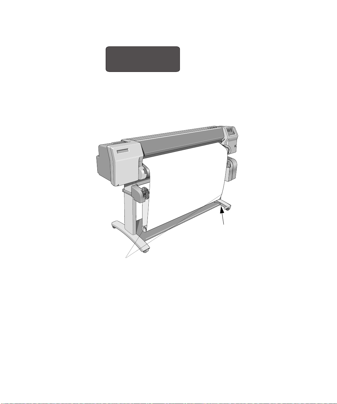
Working with Media
Loading Media onto the Take Up Reel accessory
11 Press Previous or Enter. The front panel displays:
Ready
C4704034
NOTE:When the Take Up Reel is in operation it is important to ensure that the T ake
Up Reel sensor is not blocked.
12 Shown below is how the printer should look when it is in operation. As media is fed
from the printer it drops down in a loop and up into the Take Up Reel spindle.
Make sure endcaps
are clear of media
C472347
Do not block the
Take Up Reel sensor
3-25
Page 76
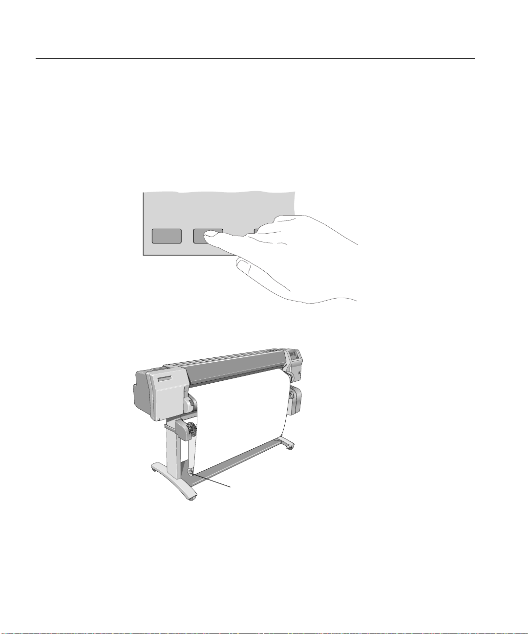
Working with Media
Unloading Media from the Take Up Reel accessory
Unloading Media from the Take Up Reel accessory
To remove media from the printer see page 3-30, Removing a Roll from the Printer.
To unload roll media from the Take Up Reel perform the following procedure.
NOTE:Before unloading media ensure the ink is dry; see page 3-44, Drying time
(With a Take Up Reel).
1 Press the Form feed and cut button on the front panel.
Form Feed
and CutCancel
C4704024
3-26
2Important: Remove the Media Weight shown below. It may help you to remove
the end-caps first.
Remove the Media Weight
C472347
Page 77
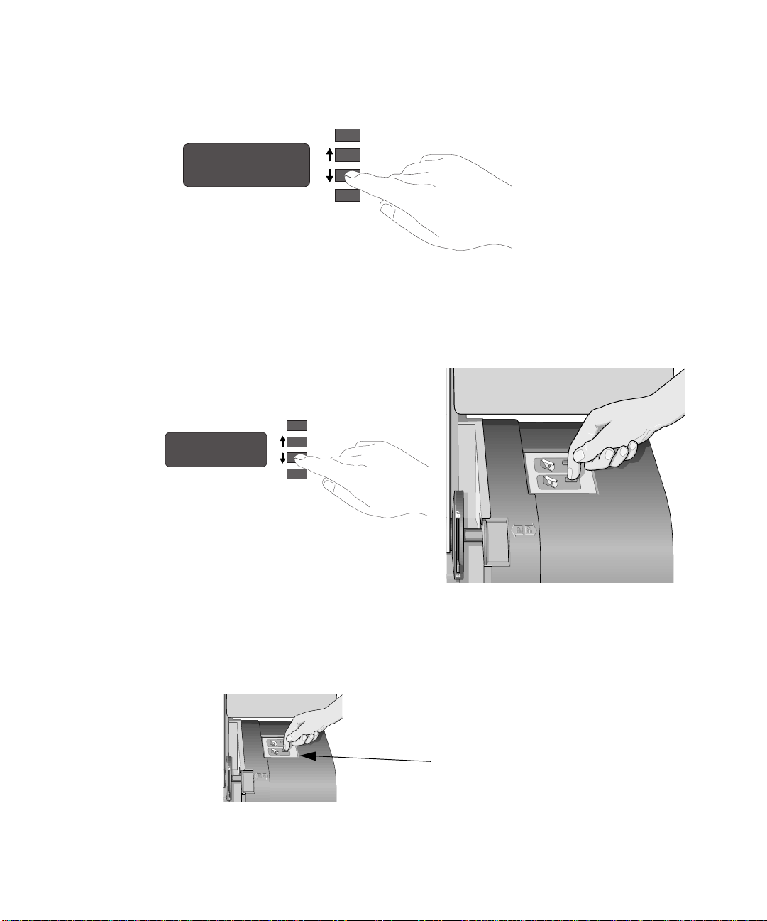
Working with Media
Unloading Media from the Take Up Reel accessory
3 The front panel displays:
Remove Media Weight
Continue----------->
C4704016
4 Press continue.
5 Press the media wind bu tton sho wn below to wind t he media hangi ng down o nto the
Take Up Reel. The front panel displays:
Wind the Take Up Reel
Cut ------------------>
C4704016
C472337
6 After winding up the Take Up Reel press the ↓ key. The cutter cuts the media.
7 Press the media wind button again on the Take Up Reel until the media is wrapped
around the core.
Media wind
button
3-27
Page 78
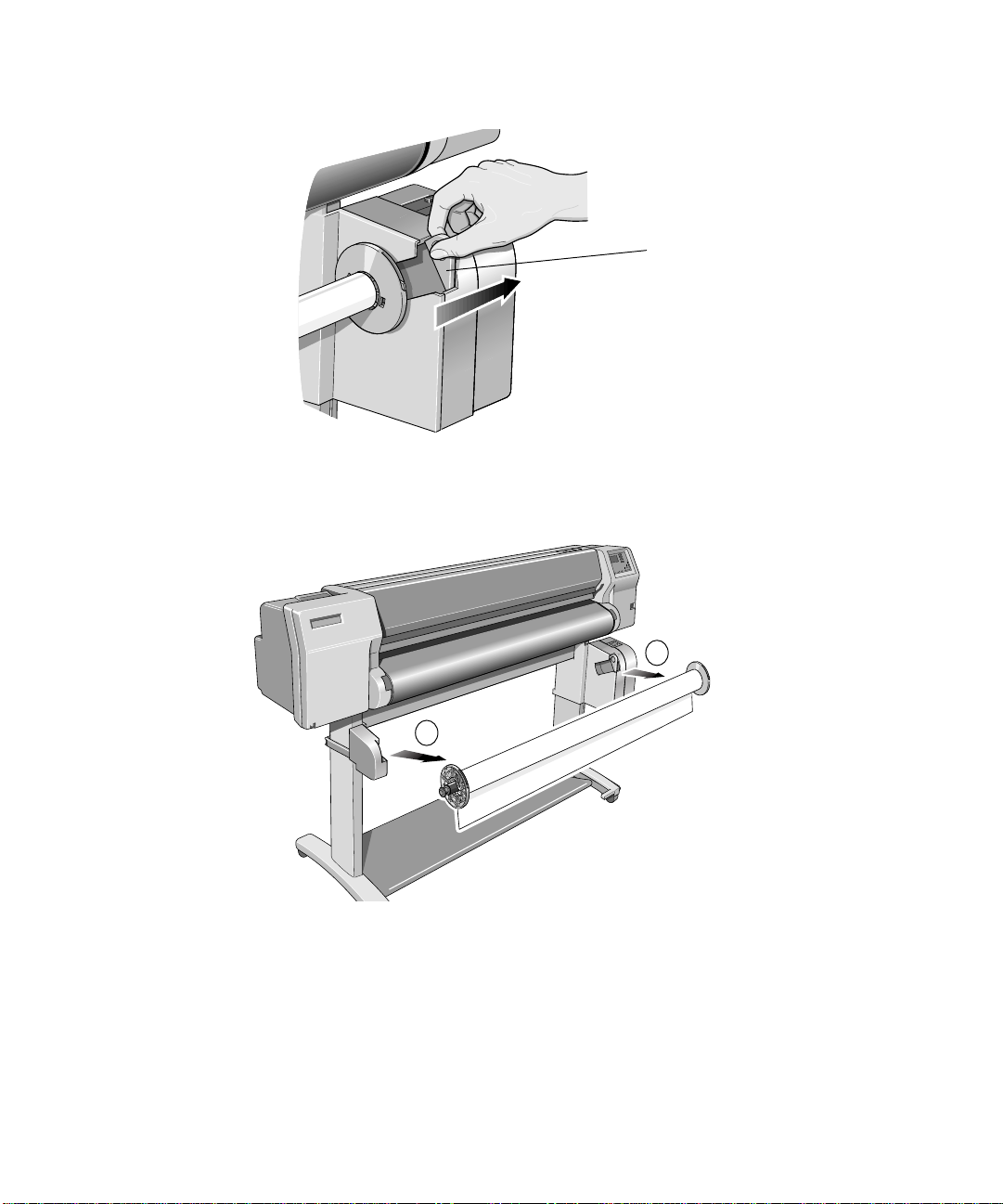
Working with Media
Unloading Media from the Take Up Reel accessory
8 Slide open the spindle lock on the right hand side of the Take Up Reel.
9 Remove the Take Up Reel spindle.
Spindle lock
C472358
3-28
A
B
C473449a
C472349a
Page 79
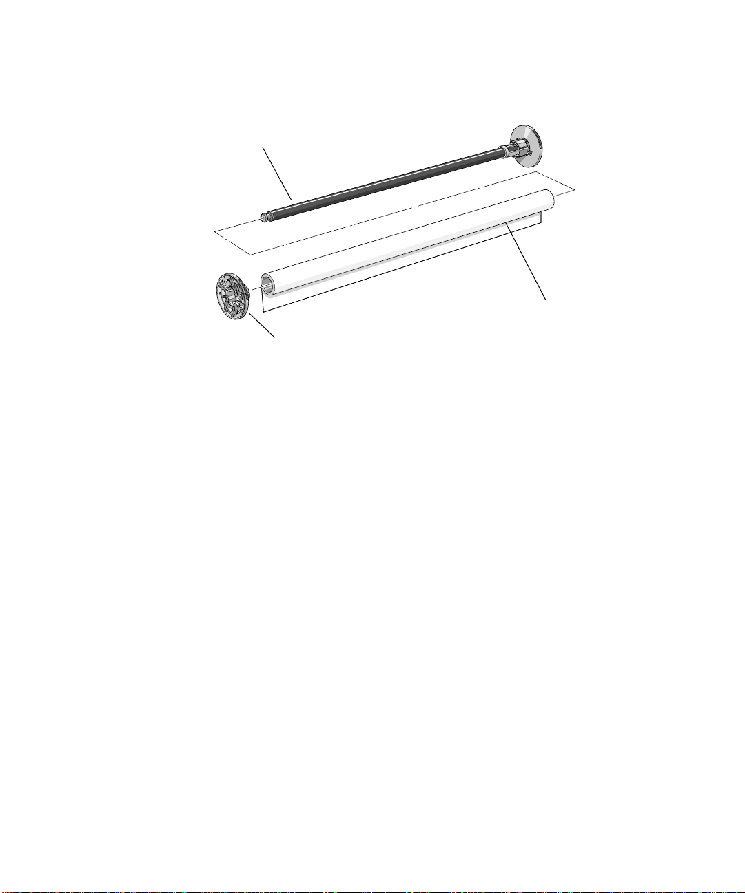
Unloading Media from the Take Up Reel accessory
10 Remove the Take Up Core from the Take Up Reel spindle.
Take Up Reel spindle
Take Up Core (with media)
Working with Media
Media
C472350c
guide
To remove roll media from the printer perform the following procedure.
3-29
Page 80

Working with Media
Removing a Roll from the Printer
Removing a Roll from the Printer
1 Wait until the appropriate drying time has passed See page 3-44, Drying time (With
a Take Up Reel)
2 Lower the Media lever.
3 Open the roll cover and turn the media stop to wind the media out of the printer and
onto the roll.
C4704130
3-30
Impom
Impomui
ioitruy
Impomui
ioitruy
C4723128a
Page 81

Working with Media
Removing a Roll from the Printer
4 Remove the old roll by pulling firmly on each end of the spindle, A then B.
B
A
C4704121a
5 Rest the old roll vertically so th at the f i xed spi ndle medi a gui de is on t he f loor. Pull
out the removable spindle media guide and then remove the roll of media from the
spindle.
C472374
6 You have completed removing the old roll media from the printer. If you are not
immediately loading another roll of media into the printer, replace the removable
spindle media guid e onto the spindle and install it back into the printer.
To load a new roll of media, continue with the next section, Installing a New Roll
into the Printer.
3-31
Page 82

Working with Media
Installing a New Roll into the Printer
Installing a New Roll into the Printer
1 If an empty spindle is installed in the printer, open the roll cover and remove the
empty spindle by pulling firmly on each end, A and then B as shown below.
B
2 Remove the new roll from its wrapping.
3 HP Heavyweight Coated Paper is the only media that is compatible with both the
HP DesignJet CP Ink System and the HP DesignJet CP Ink System UV. Therefore,
if you have changed the Ink System and the media you are loading is incompatible
with the new Ink System, the printer will automatically reject the non-com patible
media. Se e page 3-2, Choosing Media.
A
C4704118a
3-32
Page 83

Working with Media
Installing a New Roll into the Printer
4 Place the spindle vertically on the floor, with the fixed spindle media guide at the
bottom. T a ke of f the r emovable spindl e media gu ide from the top o f the spind le, and
slide the new roll onto the spindle. The leading edge of the media must wind
clockwise as shown below.
Correct Incorrect
B
B
B
A
C4723119
A
5 Install the removable spindle media guide onto the end of the spindle.
a Push down on the media guide, making sure that the guide is flush against the
ends of the roll.
b Then push the middle section in.
C4723132
3-33
Page 84

Working with Media
Installing a New Roll into the Printer
6 Insert the printer spindle so that the fixed media guide is on the right (A) and the
removable media guide is on the left (B). Push in firmly on both ends. Make sure
the media remains flush against the media stop.
B
A
C4704122a
The media must be positioned on the roll as shown above.
Media Path
3-34
Page 85

Working with Media
12'' / 305mm
Changing the Core Tube on the Take Up Reel Accessory
Changing the Core Tube on the Take Up Reel Accessory
The Core tube on the Take Up Reel must be the same width as the media you are
using. To change the core perform the following procedure.
1 Slide open the spindle lock on the right hand side of the Take Up Reel.
C472358
2 Remove the Take Up Reel spindle from the printer as shown by pulling firmly on
each end of the spindle, A then B.
A
12'' / 305mm
B
m
m
7
6
m
0
m
1
5
/
1
'
'
m
9
/
2
'
'
m
4
6
0
3
7
2
=
1
m
/
'
'
m
0
+
2
7
=
3
1
/
'
'
4
+5
5
=
+
C472349d
3-35
Page 86

Working with Media
Changing the Core Tube on the Take Up Reel Accessory
3 Remove the left-hand media guide.
4 Remove the old Take Up Core.
5 Install the new Core you have chosen onto the spindle and re-install the left hand
guide assembly.
NOTE:You can also use an empty cardboard tube to replace the plastic Take Up
Core that was supplied with yo ur printer.
It is important that the Take Up Core is the same width as the media you are using.
By matching color coded lengths of plastic tube, you can make a Take Up Core for
different widths of standard media sizes: 24”,36”.
24'' / 610mm
24'' / 610mm
+ 36''/915mm=
+ 36''/915mm=
+ 50''/1270mm=
+ 50''/1270mm=
+ 54''/1372mm=
+ 54''/1372mm=
'' / 3
2
1
C470367a
m
m
5
0
3-36
Page 87

Working with Media
Changing the Core Tube on the Take Up Reel Accessory
Alternatively you can use an empty media cardboard core.
NOTE:Ensure the Take Up Core is pushed firmly into both media guides.
NOTE:If you want to use a three inch cardboard core then use the 3 inch core
adaptors shown below.
Take Up Reel spindle
Right hand
media guide
3 inch core adaptors
m
m
5
0
3
/
''
2
1
m
m
7
6
0
m
m
'' / 1
5
1
2
9
4
/
'
'
m
6
m
0
=
7
2
1
/
'
+3
'
m
0
5
m
2
=
7
3
1
/
+
'
'
4
5
=
+
Take Up Core
C472350b
Left hand media
guide
3-37
Page 88
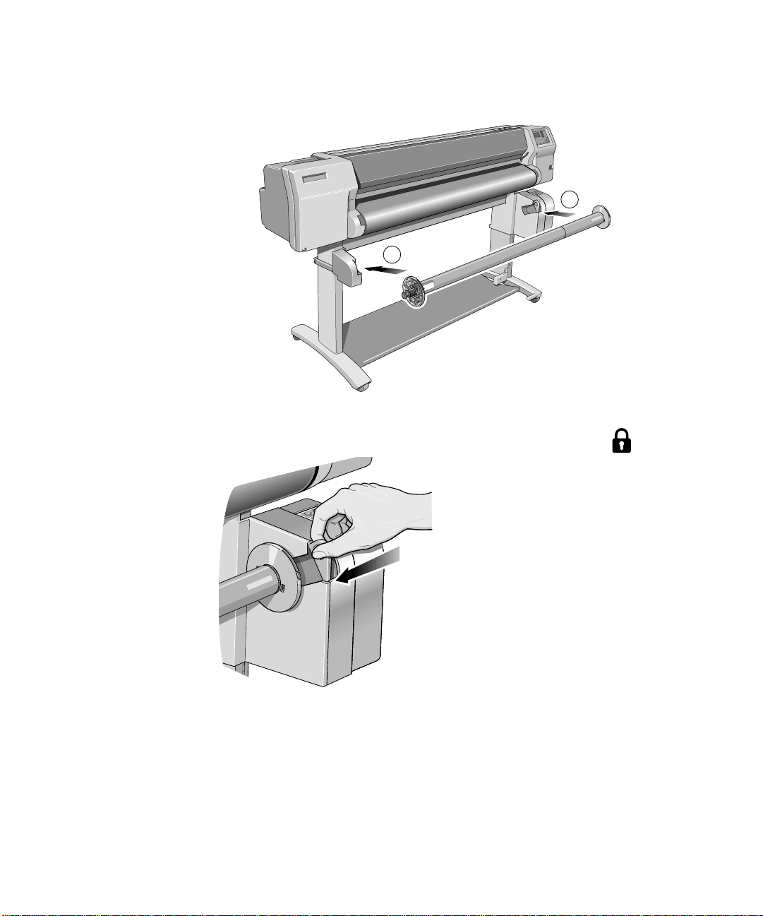
Working with Media
12'' / 305mm
Changing the Core Tube on the Take Up Reel Accessory
6 Install the Take Up Reel spindle into the printer by pushing firmly on each end of
the spindle, A then B.
7 Slide shut the spindle lock on the right-hand side of the Take Up Reel.
A
m
m
5
0
3
/
''
2
1
B
m
m
7
6
0
1
/
'
'
2
''/915mm=
4
36
+
+ 50''/1270mm=
+ 54''/1372mm=
C472349b
C472359
3-38
Page 89

Working with Media
Loading sheet media
Loading sheet media
Which edge first? You can load a sheet in either portrait or landscape orientation. Unless using the
Rotate option (see page 5-15, Rotating an Image), load the sheet in the same
orientation as you have specified in your software. If printing a PostScript file,
always load the sheet with the short edge first, even if the width of your drawing is
greater than its length.
(short edge first)
C4723020
always use this orientation for PostScript files
Which side up? As you load the sheet, it is the side facing down on which the printer prints. With
most media types, the two sides are different and so it is important to load the sheet
correctly.
Loading a sheet
1 You cannot load sheet media if roll media is loaded. If roll media is loaded refer to
3-30, Removing a Roll from the Printer.
2 Make sure the media lever is in the raised position and the roll cover is closed.
C4704131
3-39
Page 90
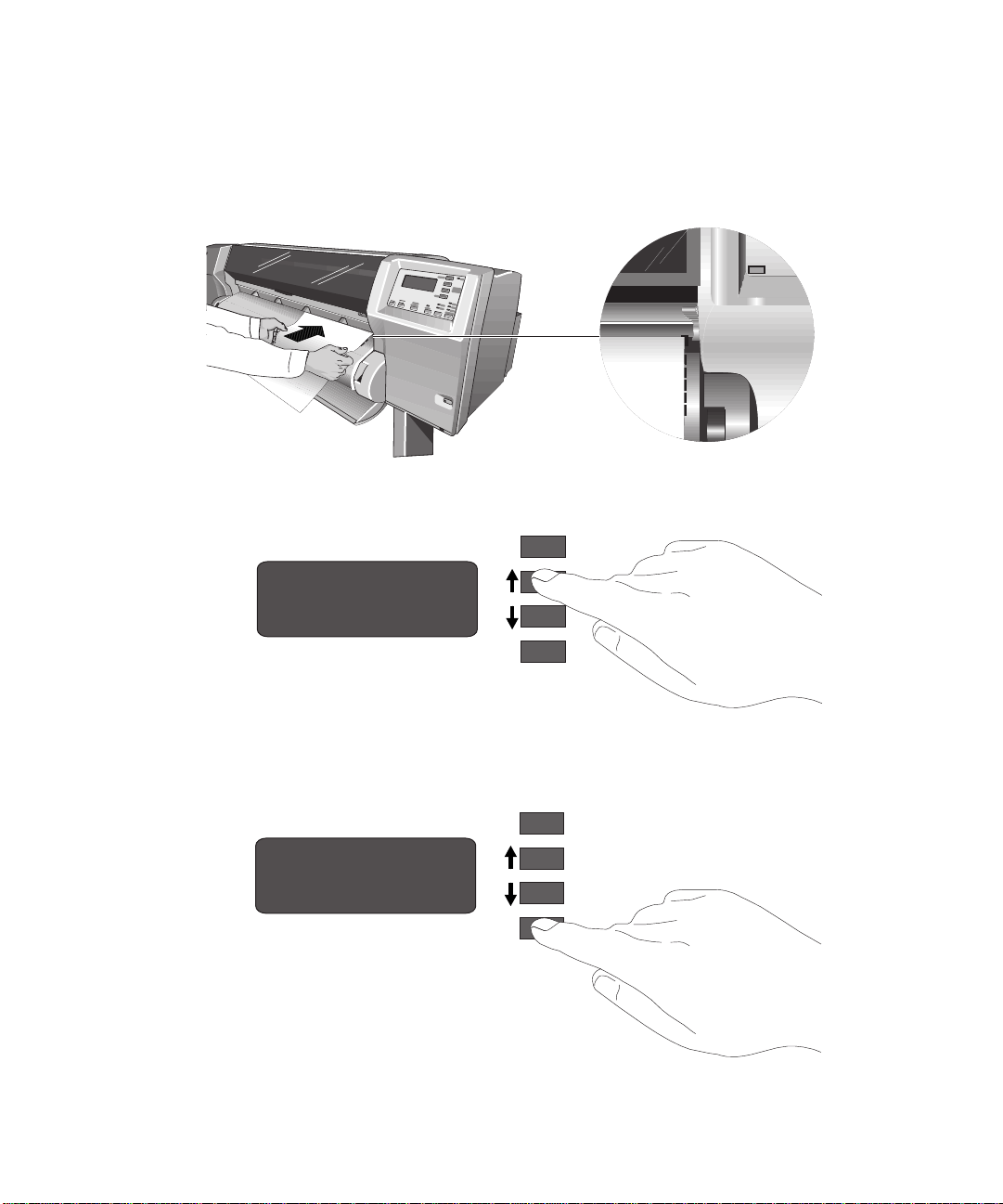
Working with Media
Cancel
Loading sheet media
3 Holding the media at its sides, align the right edge with the perforated line on the
entry platen.
4 Insert the media into the p rinter until it buckles slightly. That is, push it all the way
until the media stops. Let go of the media when the printer begins to pull it in.
C4704129a
5 Press ↑ next to the front-panel display to indicate you are loading a sheet.
Previous
Sheet load --------->
Roll load ------------>
3-40
Enter
C4704035
6 Using the ↑ and ↓ keys until the display shows the type of media you are loading*.
Then press the Enter key.
Previous
SELECT MEDIA
Coated paper
Enter
C4704030
Page 91

Working with Media
Loading sheet media
*For information on media types, see page 3-2, Choosing Media.
7 The printer moves the sheet in and out to check its size and alignment, and then
advances it to the start o f the page.
8 When the “Status/Ready “ message is displayed you have finished loading sheet
media.
3-41
Page 92
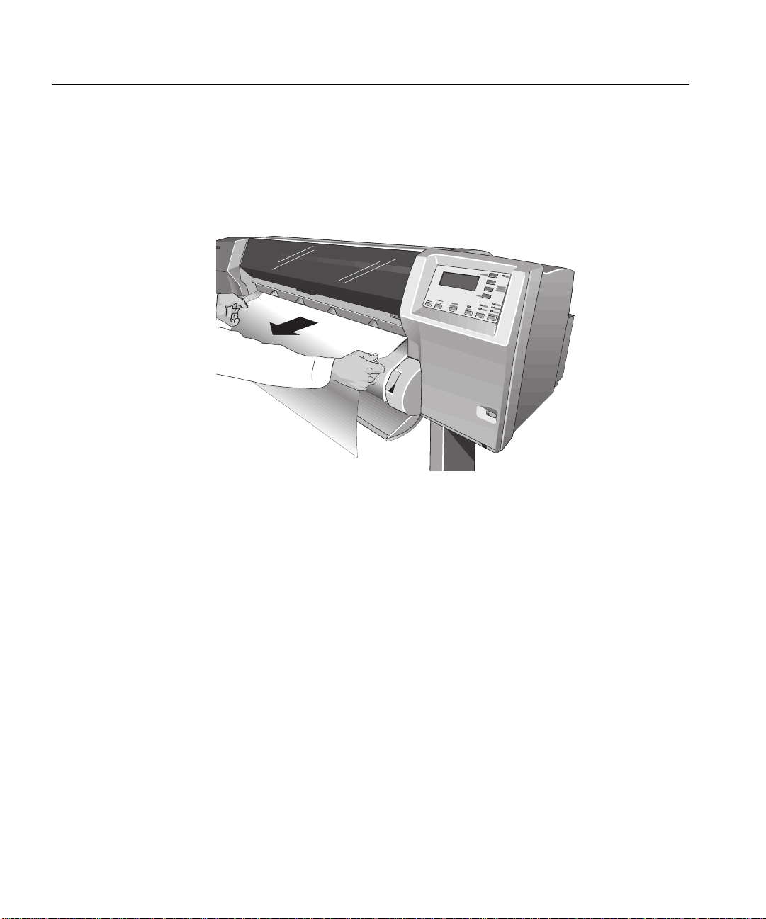
Working with Media
Unloading Sheet Media
Unloading Sheet Media
1 W ait until the appropriat e drying ti me has passed (see pa ge 3-44, Drying time (W ith a
Take Up Reel)).
and print modes.
2 Gently pull the sheet from the printer.
No drying time is necessary for some combinations of media types
3-42
C4704141a
Page 93

Working with Media
Device Setup
Skew tolerance
Unloading Sheet Media
Compensating for Badly Cut Media
If the media is persistently difficult t o load, it could be an indicatio n that it has been
cut unevenly, with the media width on the leading edge different to that of the
trailing edge. A front-pa nel opt io n cal le d Skew tol era nce hel ps yo u compen sate for
the shape of some poorly cu t sheet med ia. When you prope rly load t he l eading edge
of poorly cut media along the perforated line on the platen, you may notice the
trailing edge is displaced from the line by a small distance and the printer will not
accept the media. The printe r can acce pt poo rly cut med ia that i s displ aced less t han
1.0 cm from the perforated line.
The Skew tolerance feature is enabled only when
front panel.
NOTE Media that is cut properly should not need the help of the skew tolerance
feature. In fact, using this feature for properly cut media increases the risk of
skewing your print on the page.
Sheet media is selected on the
Adjusting Skew Tolerance
Select the appropriate skew tolerance in the front panel.
Skew Tolerance in Front
Panel
Off 0.4 cm
On 1.0 cm
Maximum Acceptable Skew of Loaded
Sheet
3-43
Page 94

Working with Media
Drying time (With a Take Up Reel)
Drying time (With a Take Up Reel)
If you are using the Take Up Reel the ink must be dry before th e media is wound up
onto the Take Up Tube, otherwise the image will be damaged. In most cases the
Take Up Reel paper loop gives the print time to dry before it is wound up, in this
case the printer will not slow down.
However sometimes the printe d media will need a longer time than this to dry, and
so the printer will slow do w n the printing process to allo w more time before being
wound onto the Take Up Reel, this is called the Drying Time.
There are three settings to Drying Time:
None
This setting means there is no delay to the printing process.
Hewlett-Packard has tested the HP media range in different environmental
conditions. The table below shows media which may need drying time and what
conditions are required to avoid it.
3-44
HP Media Type Width of printing
area
High-gloss photo 24 inches or more 60 30
Semi-gloss photo 24 inches or more 60 30
Imaging film-backlit 24 inches or more 50 35
Max.% Relative
Humidity
Max. Temperature
0
C
Page 95

Working with Media
Drying time (With a Take Up Reel)
Automatic
This is the default setting. The printer (if necessary) will a utomatically adjust the
drying time depending on the following:
n Type of Media
n Print Mode
n Width of printing area
n Environmental conditions
CAUTION To avoid the printer adding drying time to prints operate the printer under the
following environmental conditions:
HP Media Type Width of printing
area
High-gloss photo 24 inches or more 50 30
Semi-gloss photo 24 inches or more 50 30
Imaging film-backlit 24 inches or more 40 35
Max.% Relative
Humidity
Max. Temperature
0
Manual
In this mode you can override the amount of time that the printer has calculated to
print your plot. The time shown in the front panel will be the amount of time that it
will take to reach the Core on the Take Up Reel.
NOTE:However there is a certa in amount of time that the printer has to ta ke to
process your job, if the amount of time that you have specified is less than this time
the printer will ignore your setting.
C
3-45
Page 96

Working with Media
Drying Time (Without a Take Up Reel)
Drying Time (Without a Take Up Reel)
On some media types, the ink needs time to dry before the media is unloaded. The
printer automatically determines the appropriate drying time, based on the type of
media you have selected and the current temperature and humidity.
Adjusting Drying Time
You can make a global adjustment to the printer’s automatic drying times through
the front-panel menus. In almost all situations, the
excellent results.
Drying time setting Result
Automatic* T he p r inter automatically adjusts the drying time for
the current humidity and temperature.
Manual You can specify the drying time, from 1 to 10 minutes.
None The printer ejects the media immediately after printing,
without waiting for the ink to dry.
Automatic setting will provide
*For environmental specifications, see page 13-6.
CAUTION Adjusting drying times only to speed up the printer can reduce the quality of
your print.
3-46
Page 97

Working with Ink Systems
About the Ink System 4-2
Obtaining Optimum Refill Performance using non-HP media. 4-6
Monitoring the Ink Level 4-9
Removing and Replacing Ink Systems 4-11
1
4
After replacing the Ink System 4-23
Removing and Storing Partially Used Ink Systems 4-24
Storing the Ink System in the HP DesignJet CP Ink System Storage
Container 4-25
4-1
Page 98

Working with Ink Systems
About the Ink System
About the Ink System
The HP DesignJet CP Ink Systems
There are two HP DesignJet CP Ink Systems designed together with your HP
DesignJet 2500CP and 2000CP printers for a total printing solution that delivers
clear, sharp prints - every time.
n The HP DesignJet CP Ink System UV also referred to as UV Pigmented ink is
designed for use in applications where durability to direct sunlight is needed.
Because the ink has dif ferent ch aracteristics than the Imag ing Ink, pri nts will not
look exactly the same. The HP DesignJet Ink system UV is available from your
local Hewlett-Packard printer dealer.
NOTE:The Imaging and UV inks are v ery different in composition. Be careful when
installing and storing ink systems, never mix ink system components.
Main Features of the HP DesignJet CP Ink System
4-2
Designed with the HP DesignJet 2500C P and 2000CP pri nters the HP Desi gnJet CP
Ink System (Imaging Ink) delivers clear, sharp, brilliant photo-quality images with
precise performance - every time.
n The HP DesignJet CP Ink System (Imaging Ink) provides convenient, easy-to-
use printing for photo-quality images.
n The HP DesignJet CP Ink System is the Ink System that you received with your
HP DesignJet CP printer.
Page 99

Working with Ink Systems
About the Ink System
What is an Ink System?
In each of the four ink systems, there are three separate components that work
together. The components of each ink system are color-coded to help you install
them correctly.
Printhead
Ink Cartridge
Printhead Cleaner
C4704144
Ink Cartridge Each ink cartridge is a large-capacit y ink suppl y t hat refi l ls the pr int he ad whenever
the ink volume in the printhead drops below a minimum level.
Printhead The printhead has a 600-dpi thermal inkjet head for firing ink droplets onto the
media and a reservoir which holds enough in k for seve ral print s. The act ual n umber
of prints between refills depends on the size and type of images you are printing.
Printhead Cleaner The printer uses the printhead cleaner to clean and maint ain the pr inthe ad to ensure
best possible image quality, and to seal the printhead when not in use to ensure long
life.
4-3
Page 100

Working with Ink Systems
Utilities
Statistics
Ink=UV pigmented
About the Ink System
How to Identify the HP DesignJet CP Ink System UV Components
The appearance of the HP DesignJet CP Ink System UV is similar to the HP
DesignJet CP Ink System. To help you easily identify the UV Ink System each
component is marked with the following symbol after the name HP DesignJet CP
Ink System UV:
Be sure to check all components; printhead, printhead cleaner and ink cartridge for
this symbol.
Additionally, you can also identify the Ink System components by their pa rt number
(Refer to Chapter 13, Reference).
C6240008a
4-4
Identifying the Ink System in the Printer
The printer automatically detects the Ink System installed. You can easily check
which Ink System you are using from the front-panel menu display.
1 Make sure the front-panel display reads STATUS / Ready.
2 Press the Enter key and then using the ↑ or
Utilities is displayed.
3 Press the Enter key and then using the ↑ or
Statistics is displayed.
4 Press the Enter key and again using the ↑ or
you find one of these two messages:
n Ink=UV pigmented (the HP DesignJet CP Ink System UV is installed)
n Ink=Imaging (the HP DesignJet CP Ink System is installed)
5 To return to the STATUS / Ready display, press the Previous key three times.
↓
key, scroll through the menu until
↓
key, scroll through the menu until
↓
key, scroll through the menu until
 Loading...