

Page 1

HP X.25/9000 User’s Guide
HP-UX 11i v3
Edition 8
Manufacturing Part Number: J2793-90072
February 2007
© Copyright 2007 Hewlett-Packard Development Company, LP.
Page 2

Legal Notices
Copyright 2007 Hewlett-Packard Development Company, L.P.
Confidential computer software. Valid license required from HP for
possession, use or copying. Consistent with FAR 12.211 and 12.212,
Commercial Computer Software, Computer Software Documentation,
and Technical Data for Commercial Items are licensed to the U.S.
Government under vendor’s standard commercial license.
The information contained herein is subject to change without notice.
The only warranties for HP products and services are set forth in the
express warranty statements accompanying such products and services.
Nothing herein should be construed as constituting additional warranty.
HP shall not be liable for technical or editorial errors or omissions
contained herein.
UNIX is a registered trademark of The Open Group.
2
Page 3

1. About the X.25 Product
Introduction . . . . . . . . . . . . . . . . . . . . . . . . . . . . . . . . . . . . . . . . . . . . . . . . . . . . . . . . . . . 16
Application (L7), Presentation (L6), and Session (L5) Levels . . . . . . . . . . . . . . . . . . . . 18
Transport Level (L4) . . . . . . . . . . . . . . . . . . . . . . . . . . . . . . . . . . . . . . . . . . . . . . . . . . . . 19
Packet/network Level (L3). . . . . . . . . . . . . . . . . . . . . . . . . . . . . . . . . . . . . . . . . . . . . . . . 20
Data link (L2) and Physical (L1) Levels . . . . . . . . . . . . . . . . . . . . . . . . . . . . . . . . . . . . . 21
2. Installation
Before You Install the Software . . . . . . . . . . . . . . . . . . . . . . . . . . . . . . . . . . . . . . . . . . . 24
Hardware Requirements . . . . . . . . . . . . . . . . . . . . . . . . . . . . . . . . . . . . . . . . . . . . . . . 24
Installing Multiple X.25 Interface Cards . . . . . . . . . . . . . . . . . . . . . . . . . . . . . . . . . 24
Hardware Compatibility . . . . . . . . . . . . . . . . . . . . . . . . . . . . . . . . . . . . . . . . . . . . . . 24
OS Platform and Version Compatibility . . . . . . . . . . . . . . . . . . . . . . . . . . . . . . . . . 25
Memory . . . . . . . . . . . . . . . . . . . . . . . . . . . . . . . . . . . . . . . . . . . . . . . . . . . . . . . . . . . 25
Software Requirements . . . . . . . . . . . . . . . . . . . . . . . . . . . . . . . . . . . . . . . . . . . . . . . . 27
Installing the X.25 Link Software. . . . . . . . . . . . . . . . . . . . . . . . . . . . . . . . . . . . . . . . . . 28
3. Configuration
Configuring the X.25 Link. . . . . . . . . . . . . . . . . . . . . . . . . . . . . . . . . . . . . . . . . . . . . . . . 30
Using SMH . . . . . . . . . . . . . . . . . . . . . . . . . . . . . . . . . . . . . . . . . . . . . . . . . . . . . . . . . . 30
Using SMH’s On-line Help . . . . . . . . . . . . . . . . . . . . . . . . . . . . . . . . . . . . . . . . . . . . 31
Configuring an X.25 Address . . . . . . . . . . . . . . . . . . . . . . . . . . . . . . . . . . . . . . . . . . . . 31
Configuring X.25 Virtual Circuits (VCs) . . . . . . . . . . . . . . . . . . . . . . . . . . . . . . . . . . . 34
Configuring an Internet Address . . . . . . . . . . . . . . . . . . . . . . . . . . . . . . . . . . . . . . . . . 35
Verifying Level 3 Values . . . . . . . . . . . . . . . . . . . . . . . . . . . . . . . . . . . . . . . . . . . . . . . . 39
Verifying Level 2 Values . . . . . . . . . . . . . . . . . . . . . . . . . . . . . . . . . . . . . . . . . . . . . . . . 44
Configuring Remote System Access . . . . . . . . . . . . . . . . . . . . . . . . . . . . . . . . . . . . . . . . 48
Configuring X.25 over LLC2 . . . . . . . . . . . . . . . . . . . . . . . . . . . . . . . . . . . . . . . . . . . . . . 54
Configuration Files . . . . . . . . . . . . . . . . . . . . . . . . . . . . . . . . . . . . . . . . . . . . . . . . . . . . 54
Starting and Stopping Configuration . . . . . . . . . . . . . . . . . . . . . . . . . . . . . . . . . . . . . 60
Sample setup and Configuration . . . . . . . . . . . . . . . . . . . . . . . . . . . . . . . . . . . . . . . . . 61
One Lan and Two Boxes configuration . . . . . . . . . . . . . . . . . . . . . . . . . . . . . . . . . . 62
Configuring Two Lans, with One Box Per Lan . . . . . . . . . . . . . . . . . . . . . . . . . . . . 65
Troubleshooting LLC2 Configuration . . . . . . . . . . . . . . . . . . . . . . . . . . . . . . . . . . . 69
Configuring PAD Services . . . . . . . . . . . . . . . . . . . . . . . . . . . . . . . . . . . . . . . . . . . . . . . . 71
Add/Modify PAD Terminal Emulation (Local to Remote). . . . . . . . . . . . . . . . . . . . . . 71
Add/Modify PAD Support Server (Remote to Local) . . . . . . . . . . . . . . . . . . . . . . . . . . 72
Add/Modify PAD Printers Server. . . . . . . . . . . . . . . . . . . . . . . . . . . . . . . . . . . . . . . . . 73
Contents
3
Page 4

Contents
Add/Modify UUCP Server . . . . . . . . . . . . . . . . . . . . . . . . . . . . . . . . . . . . . . . . . . . . . . 73
Add/Modify X.3 Parameters . . . . . . . . . . . . . . . . . . . . . . . . . . . . . . . . . . . . . . . . . . . . . 74
Configuring the High Availability Feature. . . . . . . . . . . . . . . . . . . . . . . . . . . . . . . . . . . 76
X.25 Cluster Definition. . . . . . . . . . . . . . . . . . . . . . . . . . . . . . . . . . . . . . . . . . . . . . . . . 77
X.25 Commands to be Configured in High Availability Packages . . . . . . . . . . . . . . . 77
X.25 Package Definition . . . . . . . . . . . . . . . . . . . . . . . . . . . . . . . . . . . . . . . . . . . . . . 77
X.25 High Availability Configuration . . . . . . . . . . . . . . . . . . . . . . . . . . . . . . . . . . . 78
Checking the Configuration . . . . . . . . . . . . . . . . . . . . . . . . . . . . . . . . . . . . . . . . . . . 79
Configuring the High Availability Feature for X.25 over LLC2 . . . . . . . . . . . . . . . . . . 81
Unique MAC Address Requirement . . . . . . . . . . . . . . . . . . . . . . . . . . . . . . . . . . . . . . 81
Local Failover . . . . . . . . . . . . . . . . . . . . . . . . . . . . . . . . . . . . . . . . . . . . . . . . . . . . . . . . 82
Configuring XOL HA for Local Failover Without ServiceGuard . . . . . . . . . . . . . . 83
Remote Failover . . . . . . . . . . . . . . . . . . . . . . . . . . . . . . . . . . . . . . . . . . . . . . . . . . . . . . 86
Configuring XOL HA for Remote Failover Using Service Guard (SG) . . . . . . . . . . 86
XOL Cluster Definition. . . . . . . . . . . . . . . . . . . . . . . . . . . . . . . . . . . . . . . . . . . . . . . 88
X.25 Commands Used in the SG Package Control Scripts: . . . . . . . . . . . . . . . . . . 88
XOL Package Definition. . . . . . . . . . . . . . . . . . . . . . . . . . . . . . . . . . . . . . . . . . . . . . 89
Remote Failover with Local Failover Support Using Service Guard . . . . . . . . . . . . . 91
Verifying the X.25 Link . . . . . . . . . . . . . . . . . . . . . . . . . . . . . . . . . . . . . . . . . . . . . . . . . . 96
4. OLA/R Overview and Concepts
Introduction . . . . . . . . . . . . . . . . . . . . . . . . . . . . . . . . . . . . . . . . . . . . . . . . . . . . . . . . . . . 98
Important Terms and Concepts. . . . . . . . . . . . . . . . . . . . . . . . . . . . . . . . . . . . . . . . . . . . 99
Planning and Preparation . . . . . . . . . . . . . . . . . . . . . . . . . . . . . . . . . . . . . . . . . . . . . . . 100
Card Compatibility . . . . . . . . . . . . . . . . . . . . . . . . . . . . . . . . . . . . . . . . . . . . . . . . . . . 100
On-Line Addition. . . . . . . . . . . . . . . . . . . . . . . . . . . . . . . . . . . . . . . . . . . . . . . . . . . 100
On-Line Replacement . . . . . . . . . . . . . . . . . . . . . . . . . . . . . . . . . . . . . . . . . . . . . . 100
Critical Resources . . . . . . . . . . . . . . . . . . . . . . . . . . . . . . . . . . . . . . . . . . . . . . . . . . . . 101
Failover Actions / Single Points of Failure . . . . . . . . . . . . . . . . . . . . . . . . . . . . . . . . 102
How to On-line Replace (OLR) a J3525A PCI Card using SMH . . . . . . . . . . . . . . . . . 103
How to On-line Add (OLA) a J3525A PCI Card using SMH . . . . . . . . . . . . . . . . . . . . 107
5. Diagnostic Utilities
Using Diagnostic Utilities . . . . . . . . . . . . . . . . . . . . . . . . . . . . . . . . . . . . . . . . . . . . . . . 112
Before Using the Diagnostic Utilities . . . . . . . . . . . . . . . . . . . . . . . . . . . . . . . . . . . . . . 114
x25check and x25server. . . . . . . . . . . . . . . . . . . . . . . . . . . . . . . . . . . . . . . . . . . . . . . . . 115
4
Page 5

Example 1: Running x25check Interactively (No Parameters) . . . . . . . . . . . . . . . . 115
Example 2: Running x25check With an X.121 Address . . . . . . . . . . . . . . . . . . . . . . 117
Example 3: Running x25check With a Data Packet . . . . . . . . . . . . . . . . . . . . . . . . . 117
x25stat . . . . . . . . . . . . . . . . . . . . . . . . . . . . . . . . . . . . . . . . . . . . . . . . . . . . . . . . . . . . . . 118
Example 1: Displaying the Current Configuration. . . . . . . . . . . . . . . . . . . . . . . . . . 118
Example 2: Displaying Global Statistics . . . . . . . . . . . . . . . . . . . . . . . . . . . . . . . . . . 119
Example 3: Displaying Virtual Circuit Data Packet Counters . . . . . . . . . . . . . . . . 123
Example 4: Displaying Global X.25 Level 3 Statistics . . . . . . . . . . . . . . . . . . . . . . . 124
Example 5: Displaying X.25 Level 1 and 2 Statistics . . . . . . . . . . . . . . . . . . . . . . . . 124
Example 6: Displaying Virtual Circuit Status . . . . . . . . . . . . . . . . . . . . . . . . . . . . . 126
Example 7: Displaying Current IP to X.25 Address Mapping . . . . . . . . . . . . . . . . . 127
x25mibstat . . . . . . . . . . . . . . . . . . . . . . . . . . . . . . . . . . . . . . . . . . . . . . . . . . . . . . . . . . . 128
6. PAD Services
Introduction . . . . . . . . . . . . . . . . . . . . . . . . . . . . . . . . . . . . . . . . . . . . . . . . . . . . . . . . . . 130
CCITT Recommendations . . . . . . . . . . . . . . . . . . . . . . . . . . . . . . . . . . . . . . . . . . . . . 130
PAD services and the HP 9000 host . . . . . . . . . . . . . . . . . . . . . . . . . . . . . . . . . . . . . 131
Remote PAD Support (x29server) . . . . . . . . . . . . . . . . . . . . . . . . . . . . . . . . . . . . . . . . . 132
Overview . . . . . . . . . . . . . . . . . . . . . . . . . . . . . . . . . . . . . . . . . . . . . . . . . . . . . . . . . . . 132
Call Acceptance Mechanism and System Security . . . . . . . . . . . . . . . . . . . . . . . . 133
Supported Remote PAD Terminals . . . . . . . . . . . . . . . . . . . . . . . . . . . . . . . . . . . . 135
Configuring Remote PAD Support. . . . . . . . . . . . . . . . . . . . . . . . . . . . . . . . . . . . . . . 135
Configuring pad_spt Parameters . . . . . . . . . . . . . . . . . . . . . . . . . . . . . . . . . . . . . . 135
pad_spt Parameters . . . . . . . . . . . . . . . . . . . . . . . . . . . . . . . . . . . . . . . . . . . . . . . . 136
Launching Applications Automatically . . . . . . . . . . . . . . . . . . . . . . . . . . . . . . . . . 138
Remote PAD Printer Support (x29printd) . . . . . . . . . . . . . . . . . . . . . . . . . . . . . . . . . . 139
Overview . . . . . . . . . . . . . . . . . . . . . . . . . . . . . . . . . . . . . . . . . . . . . . . . . . . . . . . . . . . 139
System Requirements. . . . . . . . . . . . . . . . . . . . . . . . . . . . . . . . . . . . . . . . . . . . . . . . . 140
Configuring Remote PAD Printers . . . . . . . . . . . . . . . . . . . . . . . . . . . . . . . . . . . . . . 141
Configuring the UNIX Line-printer Spooler for x29printd . . . . . . . . . . . . . . . . . . . 143
Examples . . . . . . . . . . . . . . . . . . . . . . . . . . . . . . . . . . . . . . . . . . . . . . . . . . . . . . . . . . . 144
x29printd and lpsched Operation. . . . . . . . . . . . . . . . . . . . . . . . . . . . . . . . . . . . . . 144
Printer Configuration . . . . . . . . . . . . . . . . . . . . . . . . . . . . . . . . . . . . . . . . . . . . . . . 144
Verifying the Configuration . . . . . . . . . . . . . . . . . . . . . . . . . . . . . . . . . . . . . . . . . . 145
UUCP Support (x29uucpd) . . . . . . . . . . . . . . . . . . . . . . . . . . . . . . . . . . . . . . . . . . . . . . 146
Overview . . . . . . . . . . . . . . . . . . . . . . . . . . . . . . . . . . . . . . . . . . . . . . . . . . . . . . . . . . . 146
Configuring UUCP PAD Support. . . . . . . . . . . . . . . . . . . . . . . . . . . . . . . . . . . . . . . . 147
Configuring the x29hosts file . . . . . . . . . . . . . . . . . . . . . . . . . . . . . . . . . . . . . . . . . 148
Contents
5
Page 6

Contents
pad_uucp Parameters . . . . . . . . . . . . . . . . . . . . . . . . . . . . . . . . . . . . . . . . . . . . . . . 148
Configuring System and Device Files for UUCP . . . . . . . . . . . . . . . . . . . . . . . . . . . 150
Local PAD Emulation (padem) . . . . . . . . . . . . . . . . . . . . . . . . . . . . . . . . . . . . . . . . . . . 156
Command Mode . . . . . . . . . . . . . . . . . . . . . . . . . . . . . . . . . . . . . . . . . . . . . . . . . . . . . 156
Data Transfer Mode . . . . . . . . . . . . . . . . . . . . . . . . . . . . . . . . . . . . . . . . . . . . . . . . . . 157
Configuring Local PAD Emulation . . . . . . . . . . . . . . . . . . . . . . . . . . . . . . . . . . . . . . 157
Parameter Descriptions . . . . . . . . . . . . . . . . . . . . . . . . . . . . . . . . . . . . . . . . . . . . . 157
PAD Commands . . . . . . . . . . . . . . . . . . . . . . . . . . . . . . . . . . . . . . . . . . . . . . . . . . . . . . . 160
X.28 PAD Command Set. . . . . . . . . . . . . . . . . . . . . . . . . . . . . . . . . . . . . . . . . . . . . . . 160
Extended Command Set . . . . . . . . . . . . . . . . . . . . . . . . . . . . . . . . . . . . . . . . . . . . . . . 161
Configuring X.3 Profile Parameters . . . . . . . . . . . . . . . . . . . . . . . . . . . . . . . . . . . . . . . 163
Configuration Set Syntax. . . . . . . . . . . . . . . . . . . . . . . . . . . . . . . . . . . . . . . . . . . . . . 163
Parameter Values . . . . . . . . . . . . . . . . . . . . . . . . . . . . . . . . . . . . . . . . . . . . . . . . . . 164
Modifying Parameters . . . . . . . . . . . . . . . . . . . . . . . . . . . . . . . . . . . . . . . . . . . . . . . . 164
Default X.3 Parameters . . . . . . . . . . . . . . . . . . . . . . . . . . . . . . . . . . . . . . . . . . . . . . . 165
X.3 Parameter Descriptions. . . . . . . . . . . . . . . . . . . . . . . . . . . . . . . . . . . . . . . . . . . . . . 165
7. Tracing and Logging Utilities
Introduction . . . . . . . . . . . . . . . . . . . . . . . . . . . . . . . . . . . . . . . . . . . . . . . . . . . . . . . . . . 176
nettl. . . . . . . . . . . . . . . . . . . . . . . . . . . . . . . . . . . . . . . . . . . . . . . . . . . . . . . . . . . . . . . . . 178
Syntax . . . . . . . . . . . . . . . . . . . . . . . . . . . . . . . . . . . . . . . . . . . . . . . . . . . . . . . . . . . . . 178
Parameters . . . . . . . . . . . . . . . . . . . . . . . . . . . . . . . . . . . . . . . . . . . . . . . . . . . . . . . 178
Examples . . . . . . . . . . . . . . . . . . . . . . . . . . . . . . . . . . . . . . . . . . . . . . . . . . . . . . . . . . . 180
netfmt . . . . . . . . . . . . . . . . . . . . . . . . . . . . . . . . . . . . . . . . . . . . . . . . . . . . . . . . . . . . . . . 181
Syntax . . . . . . . . . . . . . . . . . . . . . . . . . . . . . . . . . . . . . . . . . . . . . . . . . . . . . . . . . . . . . 181
Parameters . . . . . . . . . . . . . . . . . . . . . . . . . . . . . . . . . . . . . . . . . . . . . . . . . . . . . . . 181
Examples . . . . . . . . . . . . . . . . . . . . . . . . . . . . . . . . . . . . . . . . . . . . . . . . . . . . . . . . . . . 182
Creating a Filter File . . . . . . . . . . . . . . . . . . . . . . . . . . . . . . . . . . . . . . . . . . . . . . . . . 183
Filter File Examples . . . . . . . . . . . . . . . . . . . . . . . . . . . . . . . . . . . . . . . . . . . . . . . . 186
strace. . . . . . . . . . . . . . . . . . . . . . . . . . . . . . . . . . . . . . . . . . . . . . . . . . . . . . . . . . . . . . . . 187
Syntax . . . . . . . . . . . . . . . . . . . . . . . . . . . . . . . . . . . . . . . . . . . . . . . . . . . . . . . . . . . . . 187
Parameters . . . . . . . . . . . . . . . . . . . . . . . . . . . . . . . . . . . . . . . . . . . . . . . . . . . . . . . 187
Examples of the strace Command . . . . . . . . . . . . . . . . . . . . . . . . . . . . . . . . . . . . . . . 192
Examples of strace Output. . . . . . . . . . . . . . . . . . . . . . . . . . . . . . . . . . . . . . . . . . . . . 193
strerr. . . . . . . . . . . . . . . . . . . . . . . . . . . . . . . . . . . . . . . . . . . . . . . . . . . . . . . . . . . . . . . . 195
Syntax . . . . . . . . . . . . . . . . . . . . . . . . . . . . . . . . . . . . . . . . . . . . . . . . . . . . . . . . . . . . . 195
6
Page 7

Parameters . . . . . . . . . . . . . . . . . . . . . . . . . . . . . . . . . . . . . . . . . . . . . . . . . . . . . . . 195
8. Troubleshooting
Troubleshooting Your X.25 Link . . . . . . . . . . . . . . . . . . . . . . . . . . . . . . . . . . . . . . . . . . 198
Troubleshooting Flowcharts and Procedures . . . . . . . . . . . . . . . . . . . . . . . . . . . . . . 199
Flowchart 2 – Procedures and Notes . . . . . . . . . . . . . . . . . . . . . . . . . . . . . . . . . . . . . 200
Note 2-1 – x25stat . . . . . . . . . . . . . . . . . . . . . . . . . . . . . . . . . . . . . . . . . . . . . . . . . . 200
Note 2-2 – eisa_config . . . . . . . . . . . . . . . . . . . . . . . . . . . . . . . . . . . . . . . . . . . . . . . 200
Flowchart 3 – Procedures and Notes . . . . . . . . . . . . . . . . . . . . . . . . . . . . . . . . . . . . . 203
Note 3-1 – Hardware Check . . . . . . . . . . . . . . . . . . . . . . . . . . . . . . . . . . . . . . . . . . 203
Flowchart 4 – Procedures and Notes . . . . . . . . . . . . . . . . . . . . . . . . . . . . . . . . . . . . . 204
Note 4-1 – x25check . . . . . . . . . . . . . . . . . . . . . . . . . . . . . . . . . . . . . . . . . . . . . . . . 204
Note 4-2 – Exit. . . . . . . . . . . . . . . . . . . . . . . . . . . . . . . . . . . . . . . . . . . . . . . . . . . . . 204
Flowchart 5 – Procedures and Notes . . . . . . . . . . . . . . . . . . . . . . . . . . . . . . . . . . . . . 205
Note 5-1 – ping . . . . . . . . . . . . . . . . . . . . . . . . . . . . . . . . . . . . . . . . . . . . . . . . . . . . 206
Note 5-2 – Checking your IP over X.25 Configuration . . . . . . . . . . . . . . . . . . . . . 206
Note 5-3 – Exit. . . . . . . . . . . . . . . . . . . . . . . . . . . . . . . . . . . . . . . . . . . . . . . . . . . . . 206
Recovering From a Power Failure . . . . . . . . . . . . . . . . . . . . . . . . . . . . . . . . . . . . . . . . . 208
For Systems With a Backup Power Supply . . . . . . . . . . . . . . . . . . . . . . . . . . . . . . . . 208
For Systems With No Backup Power Supply . . . . . . . . . . . . . . . . . . . . . . . . . . . . . . 208
Reporting Problems . . . . . . . . . . . . . . . . . . . . . . . . . . . . . . . . . . . . . . . . . . . . . . . . . . . . 209
Back-to-back Configuration on the Same Host . . . . . . . . . . . . . . . . . . . . . . . . . . . . . . 211
Configuration and Troubleshooting Commands . . . . . . . . . . . . . . . . . . . . . . . . . . . . . 212
Command Summary. . . . . . . . . . . . . . . . . . . . . . . . . . . . . . . . . . . . . . . . . . . . . . . . . . 212
Examples of x25init . . . . . . . . . . . . . . . . . . . . . . . . . . . . . . . . . . . . . . . . . . . . . . . . . . 214
IP-to-X.121 Address Mapping Table . . . . . . . . . . . . . . . . . . . . . . . . . . . . . . . . . . . . . 214
Example . . . . . . . . . . . . . . . . . . . . . . . . . . . . . . . . . . . . . . . . . . . . . . . . . . . . . . . . . . 216
File Mapping Parameters. . . . . . . . . . . . . . . . . . . . . . . . . . . . . . . . . . . . . . . . . . . . . . 216
Contents
A. Using Non-English Subscription Forms
Subscription Form Translations . . . . . . . . . . . . . . . . . . . . . . . . . . . . . . . . . . . . . . . . . . 220
B. X.25 Configuration Files and Examples
X.25 Configuration Files . . . . . . . . . . . . . . . . . . . . . . . . . . . . . . . . . . . . . . . . . . . . . . . . 226
Example Files. . . . . . . . . . . . . . . . . . . . . . . . . . . . . . . . . . . . . . . . . . . . . . . . . . . . . . . . . 228
The x25init_def File . . . . . . . . . . . . . . . . . . . . . . . . . . . . . . . . . . . . . . . . . . . . . . . . . . 228
The x25init_smpl File. . . . . . . . . . . . . . . . . . . . . . . . . . . . . . . . . . . . . . . . . . . . . . . . . 231
The x3config File. . . . . . . . . . . . . . . . . . . . . . . . . . . . . . . . . . . . . . . . . . . . . . . . . . . . . 233
7
Page 8

Contents
The x29hosts File . . . . . . . . . . . . . . . . . . . . . . . . . . . . . . . . . . . . . . . . . . . . . . . . . . . . 236
The Network Type File (x25_networks) . . . . . . . . . . . . . . . . . . . . . . . . . . . . . . . . . . 237
C. Diagnostic Messages
Introduction . . . . . . . . . . . . . . . . . . . . . . . . . . . . . . . . . . . . . . . . . . . . . . . . . . . . . . . . . . 240
Diagnostic Message Example . . . . . . . . . . . . . . . . . . . . . . . . . . . . . . . . . . . . . . . . . . . . 241
Cause Code Settings . . . . . . . . . . . . . . . . . . . . . . . . . . . . . . . . . . . . . . . . . . . . . . . . . . . 242
Packet Codes. . . . . . . . . . . . . . . . . . . . . . . . . . . . . . . . . . . . . . . . . . . . . . . . . . . . . . . . . . 243
RESTART Packet Codes. . . . . . . . . . . . . . . . . . . . . . . . . . . . . . . . . . . . . . . . . . . . . . . 243
RESET/CLEAR Packet Codes . . . . . . . . . . . . . . . . . . . . . . . . . . . . . . . . . . . . . . . . . . 243
X.25 Diagnostic Messages . . . . . . . . . . . . . . . . . . . . . . . . . . . . . . . . . . . . . . . . . . . . . . . 244
8
Page 9

Tab les
Table 2-1. . . . . . . . . . . . . . . . . . . . . . . . . . . . . . . . . . . . . . . . . . . . . . . . . . . . . . . . . . . . .26
Table 3-1. Field Descriptions . . . . . . . . . . . . . . . . . . . . . . . . . . . . . . . . . . . . . . . . . . . . .33
Table 3-2. Field Descriptions . . . . . . . . . . . . . . . . . . . . . . . . . . . . . . . . . . . . . . . . . . . . .35
Table 3-3. Configure Internet Address Field Descriptions . . . . . . . . . . . . . . . . . . . . .37
Table 3-4. IP Address and Default Subnet Masks . . . . . . . . . . . . . . . . . . . . . . . . . . . .37
Table 3-5. Modify IP over X.25 Defaults Field Descriptions . . . . . . . . . . . . . . . . . . . .39
Table 3-6. Verify Level 3 Values Field Descriptions . . . . . . . . . . . . . . . . . . . . . . . . . . .40
Table 3-7. Switched VC Flow Control Field Descriptions . . . . . . . . . . . . . . . . . . . . . .42
Table 3-8. Permanent VC Flow Control Field Descriptions. . . . . . . . . . . . . . . . . . . . .42
Table 3-9. Modify Throughput Class Settings Field Descriptions. . . . . . . . . . . . . . . .43
Table 3-10. Throughput Classes and Line Speeds . . . . . . . . . . . . . . . . . . . . . . . . . . . .44
Table 3-11. Verify Level 2 Values Field Descriptions . . . . . . . . . . . . . . . . . . . . . . . . . .46
Table 3-12. Add Internet Connectivity Field Descriptions . . . . . . . . . . . . . . . . . . . . .50
Table 3-13. Provide X.25 Information Field Descriptions . . . . . . . . . . . . . . . . . . . . . .52
Table 3-14. Additional XOL specific configuration parameters. . . . . . . . . . . . . . . . . .55
Table 4-1. Terms used in this section . . . . . . . . . . . . . . . . . . . . . . . . . . . . . . . . . . . . . .99
Table 4-2. Three Possible Critical Resource Analysis (CRA) Outcomes . . . . . . . . . .104
Table 4-3. Three Possible Critical Resource Analysis (CRA) Outcomes . . . . . . . . . .108
Table 5-1. Available Diagnostic Utilities. . . . . . . . . . . . . . . . . . . . . . . . . . . . . . . . . . .112
Table 5-2. Level 3 State . . . . . . . . . . . . . . . . . . . . . . . . . . . . . . . . . . . . . . . . . . . . . . . .120
Table 5-3. Level 2 Link State. . . . . . . . . . . . . . . . . . . . . . . . . . . . . . . . . . . . . . . . . . . .121
Table 5-4. Level 1 Link State. . . . . . . . . . . . . . . . . . . . . . . . . . . . . . . . . . . . . . . . . . . .122
Table 5-5. Statistics for WAN Output . . . . . . . . . . . . . . . . . . . . . . . . . . . . . . . . . . . . .122
Table 5-6. VC State . . . . . . . . . . . . . . . . . . . . . . . . . . . . . . . . . . . . . . . . . . . . . . . . . . .123
Table 5-7. Statistics for WAN Output . . . . . . . . . . . . . . . . . . . . . . . . . . . . . . . . . . . . .126
Table 5-8. Example Statistics for x25mibstat. . . . . . . . . . . . . . . . . . . . . . . . . . . . . . .128
Table 6-1. . . . . . . . . . . . . . . . . . . . . . . . . . . . . . . . . . . . . . . . . . . . . . . . . . . . . . . . . . . .148
Table 6-2. X.3 Parameter Descriptions . . . . . . . . . . . . . . . . . . . . . . . . . . . . . . . . . . . .166
Table 6-3. . . . . . . . . . . . . . . . . . . . . . . . . . . . . . . . . . . . . . . . . . . . . . . . . . . . . . . . . . . .166
Table 6-4. . . . . . . . . . . . . . . . . . . . . . . . . . . . . . . . . . . . . . . . . . . . . . . . . . . . . . . . . . . .167
Table 6-6. . . . . . . . . . . . . . . . . . . . . . . . . . . . . . . . . . . . . . . . . . . . . . . . . . . . . . . . . . . .168
Table 6-5. . . . . . . . . . . . . . . . . . . . . . . . . . . . . . . . . . . . . . . . . . . . . . . . . . . . . . . . . . . .168
Table 6-7. . . . . . . . . . . . . . . . . . . . . . . . . . . . . . . . . . . . . . . . . . . . . . . . . . . . . . . . . . . .169
Table 6-8. . . . . . . . . . . . . . . . . . . . . . . . . . . . . . . . . . . . . . . . . . . . . . . . . . . . . . . . . . . .170
Table 6-9. . . . . . . . . . . . . . . . . . . . . . . . . . . . . . . . . . . . . . . . . . . . . . . . . . . . . . . . . . . .170
9
Page 10

Tables
Table 6-10. . . . . . . . . . . . . . . . . . . . . . . . . . . . . . . . . . . . . . . . . . . . . . . . . . . . . . . . . . .171
Table 6-12. . . . . . . . . . . . . . . . . . . . . . . . . . . . . . . . . . . . . . . . . . . . . . . . . . . . . . . . . . .172
Table 6-13. . . . . . . . . . . . . . . . . . . . . . . . . . . . . . . . . . . . . . . . . . . . . . . . . . . . . . . . . . .172
Table 6-11. . . . . . . . . . . . . . . . . . . . . . . . . . . . . . . . . . . . . . . . . . . . . . . . . . . . . . . . . . .172
Table 6-14. . . . . . . . . . . . . . . . . . . . . . . . . . . . . . . . . . . . . . . . . . . . . . . . . . . . . . . . . . .173
Table 6-15. . . . . . . . . . . . . . . . . . . . . . . . . . . . . . . . . . . . . . . . . . . . . . . . . . . . . . . . . . .173
Table 6-16. . . . . . . . . . . . . . . . . . . . . . . . . . . . . . . . . . . . . . . . . . . . . . . . . . . . . . . . . . .174
Table 7-1. Available Tracing and Logging Utilities . . . . . . . . . . . . . . . . . . . . . . . . . .176
Table 7-2. Tracing Masks. . . . . . . . . . . . . . . . . . . . . . . . . . . . . . . . . . . . . . . . . . . . . . .179
Table 7-3. Filter File Options. . . . . . . . . . . . . . . . . . . . . . . . . . . . . . . . . . . . . . . . . . . .184
Table 7-4. Filter File family Options . . . . . . . . . . . . . . . . . . . . . . . . . . . . . . . . . . . . . .185
Table 7-5. Single-port Subnet Interface Codes . . . . . . . . . . . . . . . . . . . . . . . . . . . . . .188
Table 7-6. Dual-port Subnet Interface Codes . . . . . . . . . . . . . . . . . . . . . . . . . . . . . . .189
Table 7-7. Output Format . . . . . . . . . . . . . . . . . . . . . . . . . . . . . . . . . . . . . . . . . . . . . .190
Table 7-8. . . . . . . . . . . . . . . . . . . . . . . . . . . . . . . . . . . . . . . . . . . . . . . . . . . . . . . . . . . .191
Table 7-9. . . . . . . . . . . . . . . . . . . . . . . . . . . . . . . . . . . . . . . . . . . . . . . . . . . . . . . . . . . .191
Table 7-10. Output Format . . . . . . . . . . . . . . . . . . . . . . . . . . . . . . . . . . . . . . . . . . . . .192
Table 7-11. . . . . . . . . . . . . . . . . . . . . . . . . . . . . . . . . . . . . . . . . . . . . . . . . . . . . . . . . . .193
Table 8-1. Troubleshooting Commands. . . . . . . . . . . . . . . . . . . . . . . . . . . . . . . . . . . .198
Table A-1. French TRANSPAC Subscription Form . . . . . . . . . . . . . . . . . . . . . . . . . .220
Table A-2. Using Your ITAPAC (Italian) Subscription Form. . . . . . . . . . . . . . . . . . .221
Table A-3. Using your DATEX-P (German) Subscription Form . . . . . . . . . . . . . . . .222
Table A-4. Using your IBERPAC (Spanish) Subscription Form . . . . . . . . . . . . . . . .222
Table B-1. /etc/x25 directory . . . . . . . . . . . . . . . . . . . . . . . . . . . . . . . . . . . . . . . . . . . .226
Table B-2. /etc directory . . . . . . . . . . . . . . . . . . . . . . . . . . . . . . . . . . . . . . . . . . . . . . . .226
Table B-3. /var/x25/log/x25server directory . . . . . . . . . . . . . . . . . . . . . . . . . . . . . . . .227
Table B-4. /var/x25/log directory . . . . . . . . . . . . . . . . . . . . . . . . . . . . . . . . . . . . . . . . .227
Table B-5. Home directory . . . . . . . . . . . . . . . . . . . . . . . . . . . . . . . . . . . . . . . . . . . . . .227
Table B-6. . . . . . . . . . . . . . . . . . . . . . . . . . . . . . . . . . . . . . . . . . . . . . . . . . . . . . . . . . . .228
Table B-7. . . . . . . . . . . . . . . . . . . . . . . . . . . . . . . . . . . . . . . . . . . . . . . . . . . . . . . . . . . .231
Table B-8. . . . . . . . . . . . . . . . . . . . . . . . . . . . . . . . . . . . . . . . . . . . . . . . . . . . . . . . . . . .236
Table B-9. . . . . . . . . . . . . . . . . . . . . . . . . . . . . . . . . . . . . . . . . . . . . . . . . . . . . . . . . . . .238
Table C-1. No Additional Information. . . . . . . . . . . . . . . . . . . . . . . . . . . . . . . . . . . . .244
Table C-2. Packet Type Invalid . . . . . . . . . . . . . . . . . . . . . . . . . . . . . . . . . . . . . . . . . .244
Table C-3. Packet Not Allowed . . . . . . . . . . . . . . . . . . . . . . . . . . . . . . . . . . . . . . . . . .245
10
Page 11

Tab les
Table C-4. Timer Expired. . . . . . . . . . . . . . . . . . . . . . . . . . . . . . . . . . . . . . . . . . . . . . .246
Table C-5. Call Setup, Call Clearing, or Registration Problem . . . . . . . . . . . . . . . . .247
Table C-6. CATEGORY - Miscellaneous . . . . . . . . . . . . . . . . . . . . . . . . . . . . . . . . . . .251
Table C-7. International Problem and Maintenance . . . . . . . . . . . . . . . . . . . . . . . . .251
Table C-8. DTE-Specific Signals . . . . . . . . . . . . . . . . . . . . . . . . . . . . . . . . . . . . . . . . .251
Table C-9. OSI Network Service Problem. . . . . . . . . . . . . . . . . . . . . . . . . . . . . . . . . .253
Table C-10. Higher Level Initiated . . . . . . . . . . . . . . . . . . . . . . . . . . . . . . . . . . . . . . .254
11
Page 12

Tables
12
Page 13

Figures
Figure 1-1. X.25 Link Architecture . . . . . . . . . . . . . . . . . . . . . . . . . . . . . . . . . . . . . . . .17
Figure 3-1. . . . . . . . . . . . . . . . . . . . . . . . . . . . . . . . . . . . . . . . . . . . . . . . . . . . . . . . . . . .32
Figure 3-2. . . . . . . . . . . . . . . . . . . . . . . . . . . . . . . . . . . . . . . . . . . . . . . . . . . . . . . . . . . .34
Figure 3-3. Configure Internet Address . . . . . . . . . . . . . . . . . . . . . . . . . . . . . . . . . . . .36
Figure 3-4. Modify IP Over X.25 Defaults . . . . . . . . . . . . . . . . . . . . . . . . . . . . . . . . . .38
Figure 3-5. Verify Level 3 Values . . . . . . . . . . . . . . . . . . . . . . . . . . . . . . . . . . . . . . . . .40
Figure 3-6. . . . . . . . . . . . . . . . . . . . . . . . . . . . . . . . . . . . . . . . . . . . . . . . . . . . . . . . . . . .41
Figure 3-7. . . . . . . . . . . . . . . . . . . . . . . . . . . . . . . . . . . . . . . . . . . . . . . . . . . . . . . . . . . .43
Figure 3-8. . . . . . . . . . . . . . . . . . . . . . . . . . . . . . . . . . . . . . . . . . . . . . . . . . . . . . . . . . . .45
Figure 3-9. Add Internet Connectivity Dialog . . . . . . . . . . . . . . . . . . . . . . . . . . . . . . .49
Figure 3-10. . . . . . . . . . . . . . . . . . . . . . . . . . . . . . . . . . . . . . . . . . . . . . . . . . . . . . . . . . .51
Figure 3-11. One LAN, Two Boxes Configuration . . . . . . . . . . . . . . . . . . . . . . . . . . . .62
Figure 3-12. Two Lans, One Box per Lan configuration . . . . . . . . . . . . . . . . . . . . . . .66
Figure 3-13. Before the Failover . . . . . . . . . . . . . . . . . . . . . . . . . . . . . . . . . . . . . . . . . .83
Figure 3-14. After the Failover . . . . . . . . . . . . . . . . . . . . . . . . . . . . . . . . . . . . . . . . . . .84
Figure 3-15. Before the Failover . . . . . . . . . . . . . . . . . . . . . . . . . . . . . . . . . . . . . . . . . .87
Figure 3-16. After the Failover . . . . . . . . . . . . . . . . . . . . . . . . . . . . . . . . . . . . . . . . . . .88
Figure 5-1. Scope of X.25 Diagnostic Utilities . . . . . . . . . . . . . . . . . . . . . . . . . . . . . .113
Figure 6-1. PAD Support Protocols . . . . . . . . . . . . . . . . . . . . . . . . . . . . . . . . . . . . . . .131
Figure 6-2. PAD Services as a Pipe. . . . . . . . . . . . . . . . . . . . . . . . . . . . . . . . . . . . . . .132
Figure 6-3. Remote PAD Support . . . . . . . . . . . . . . . . . . . . . . . . . . . . . . . . . . . . . . . .133
Figure 6-4. . . . . . . . . . . . . . . . . . . . . . . . . . . . . . . . . . . . . . . . . . . . . . . . . . . . . . . . . . .134
Figure 6-5. Remote Printer Support . . . . . . . . . . . . . . . . . . . . . . . . . . . . . . . . . . . . . .140
Figure 6-6. Remote Printer Support . . . . . . . . . . . . . . . . . . . . . . . . . . . . . . . . . . . . . .147
Figure 6-7. . . . . . . . . . . . . . . . . . . . . . . . . . . . . . . . . . . . . . . . . . . . . . . . . . . . . . . . . . .156
Figure 7-1. The Scope of X.25 Tracing and Logging Utilities . . . . . . . . . . . . . . . . . .177
Figure 7-2. . . . . . . . . . . . . . . . . . . . . . . . . . . . . . . . . . . . . . . . . . . . . . . . . . . . . . . . . . .188
Figure 8-1. Flowchart 1 . . . . . . . . . . . . . . . . . . . . . . . . . . . . . . . . . . . . . . . . . . . . . . . .200
Figure 8-2. Flowchart 2 – Initialization Check. . . . . . . . . . . . . . . . . . . . . . . . . . . . . .202
Figure 8-3. Flowchart 3 – Hardware Check . . . . . . . . . . . . . . . . . . . . . . . . . . . . . . . .203
Figure 8-4. Flowchart 4 – X.25 Configuration Check. . . . . . . . . . . . . . . . . . . . . . . . .205
Figure 8-5. Flowchart 5 – IP Over X.25 Check. . . . . . . . . . . . . . . . . . . . . . . . . . . . . .207
Figure 8-6. . . . . . . . . . . . . . . . . . . . . . . . . . . . . . . . . . . . . . . . . . . . . . . . . . . . . . . . . . .211
13
Page 14

Figures
14
Page 15

1 About the X.25 Product
Chapter 1 15
Page 16

About the X.25 Product
Introduction
Introduction
The Hewlett-Packard X.25 link for HP 9000 systems provides
networking link hardware and software to allow HP computer systems to
communicate with other HP and non-HP computers over X.25 packet
switching networks.
The X.25 link implements the CCITT X.25 Recommendations and
contains the components necessary to connect an HP 9000 to a public or
private packet switching network conforming to the CCITT X.25
Recommendation (1980, 1984 or 1988), or to another system in a
back-to-back configuration.
The information in this manual applies to HP 9000 Series 700 and 800
systems that use single, dual, or quad-port communications hardware.
Any differences are specifically noted.
NOTE In a diskless cluster, X.25 software is only supported on the server
system. It is not supported on client systems for this type of
environment.
The following diagram illustrates the X.25 link architecture where:
• solid white boxes represent the product’s integral components.
• lightly shaded boxes represent the product’s protocol components.
• heavily shaded boxes represent optional components (external to the
product) that can be added to the product.
Each component depends on the component(s) below it and must be
installed and running in order to support higher-level components.
Chapter 116
Page 17
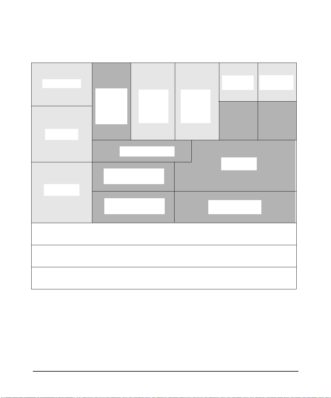
Figure 1-1 X.25 Link Architecture
About the X.25 Product
Introduction
OSI Services
OTS/9000
OTS-to-PLP
Translator
X.25
PAD
Services
X.25
Programmatic Access
BSD-to-PLP Translator
X.25 Packet Level Protocol (PLP)
X.25 Link Access Procedure-Balanced Protocol (LAP-B)
User
Written
L3
BSD IP C
User
Written
L4
IP-to-PLP Interface
Internet
Services
TCP/UDP
Network
Services NS
X.25 Communications Hardware
Chapter 1 17
Page 18

About the X.25 Product
Application (L7), Presentat ion (L 6), and Session (L5) Levels
Application (L7), Presentation (L6), and
Session (L5) Levels
The X.25 link does not provide any components for the general support of
the application and presentation levels (levels 7 and 6, respectively),
although X.25/9000 PAD Services do provide some of the functionality of
these levels.
User-written application programs, Internet Services/Berkeley Services
(via BSD Sockets) and NS (via NetIPC Sockets), are accessed by means
of TCP or UDP Transport Level (level 4) protocols.
For application level services, you can install OSI Services to run over
the X.25 network (for more information, refer to OSI Services
documentation). The OTS/9000 product provides access to X.25 for OSI
Services. You can install application level services such as
Internet/Berkeley Services and Network Services (for more information,
refer to the documentation for these products).
BSD IPC (Berkeley Software Distribution InterProcess Communication)
allows direct programmatic access to the X.25 packet level (level 3), or
TCP/UDP at the transport level (level 4), for user-written application
programs.
NetIPC sockets also provides a programmatic interface to TCP/UDP at
the transport level.
Chapter 118
Page 19

About the X.25 Product
Transport Level (L4)
Transport Level (L4)
At the transport level (level 4), the X.25 link provides TCP (based on the
DARPA standard) and UDP. These Transport level protocols are used by
Internet/Berkeley Services, by NS, and by user application programs
that access the TCP/UDP and IP protocols.
The TCP protocol is a connection-based protocol. TCP verifies that all
data is delivered without duplication to its destination. The UDP
protocol, unlike TCP, has no concept of a connection. Messages are sent
as a unit with source and destination information in the header.
The X.25 link provides a BSD to PLP (Packet Level Protocol) translator
to allow access to PLP at level 3 for user-written application programs
via BSD IPC.
The X.25 link also provides an OTS to PLP translator to allow access to
PLP at level 3 for OSI Services via Xport OSI.
Chapter 1 19
Page 20

About the X.25 Product
Packet/network Level (L3)
Packet/network Level (L3)
At the packet/network level (L3), X.25 link provides direct X.25
programmatic access via BSD IPC. For full details on X.25 programmatic
access, refer to the X.25/9000 Programmer’s guide (part number:
J2793-90065).
The X.25 link also provides IP access to TCP or UDP Transport protocols
for programs such as Internet/Berkeley Services and NS, allowing
communication over X.25 in accordance with RFC 877.
Chapter 120
Page 21

About the X.25 Product
Data link (L2) and Physical (L1) Levels
Data link (L2) and Physical (L1) Levels
At the data link level (level 2), the X.25 link provides the LAP-B (Link
Access Procedure-Balanced) protocol. LAP-B is a data link protocol,
specified by the 1980 CCITT X.25 recommendations, that determines
frame exchange procedures.
At the physical level (level 1), the X.25 link provides support for X.21,
X.21bis, and V.35 interfaces (depending on your particular
communications hardware). These sets of recommendations define the
standards for X.25 at the physical level and apply specifically to
connections to a packet switching network. X.21bis (equivalent to V.24
and RS-232) is applicable to X.25 physical interfaces with transmission
speeds up to 64 kb/s. V.35, RS-449, X.21, and RS-530 supports
transmission speeds up to 2 Mb/s. Other standards may also be
supported as they become available.
Chapter 1 21
Page 22

About the X.25 Product
Data link (L2) and Physical (L1) Levels
Chapter 122
Page 23

2 Installation
Chapter 2 23
Page 24

Installation
Before You Install the Software
Before You Install the Software
Before installing the X.25 link software, check the requirements below to
make sure that all required software and hardware has been correctly
installed and configured.
NOTE This product is only supported on the system that is acting as a server. It
is not supported on client systems.
Hardware Requirements
This section describes the hardware requirements of the J2793B X.25
software for HP 9000 server systems.
If you have not already done so, install the X.25 interface card as
described in the hardware installation guide for your X.25 product. If you
are installing multiple X.25 cards, check the requirements in “Installing
Multiple X.25 Interface Cards” below.
If a modem connection is required, connect the X.25 card to the modem
or the modem eliminator according either to the modem vendor’s
specification sheet, or the instructions provided by the network provider.
Installing Multiple X.25 Interface Cards
When installing multiple X.25 cards,
• Always install the cards in adjacent slots in ascending slot order.
• Always install X.25 cards with the system shut down.
• Do not skip slots between X.25 cards.
Hardware Compatibility
• HP 9000 PCI bus
The High Availability feature can run on:
• PCI hardware cards, Product Numbers J3525A (2-ports)
Chapter 224
Page 25

Installation
Before You Install the Software
OS Platform and Version Compatibility
The version of the X.25 link software you’re installing must be
compatible with the version of HP-UX you’re running (for example,
HP-UX version 11i v3 for B.11.31.01)
• Disk space required to install: 7 Mb
• Software install with system up or down? Up
• Single-user state required or recommended? No
• Reboot? Yes
Memory
Your X.25 link supports a high number of virtual circuits operating at
high baud rates. Since both X.25 and the BSD sockets API may store a
certain amount of data for each socket/circuit, HP recommends that you
check that your system has enough memory to handle the number of VCs
you plan to use. A few guidelines to help you are provided below.
Related Parameters
• Level 3 window size (W in formulas below) as configured in the
x25config file
• Level 3 packet size (P in formulas below) as configured in X.25
configuration file
• Socket buffer size (B in formulas below) used in your applications
(setsockopt() system call). The default is 4 Kb.
Evaluation Formulas The following formulas can be used to evaluate
X.25 memory requirements:
Memory for each VC (MVC) in bytes:
MVC = (B x 3) + (2 x (W + 1) x P)
Total Memory (TM) for X.25 in bytes:
TM = sum (MVC) + Number of cards x 5120
NOTE These figures are only for protocol and API requirements. You should
also consider the memory required by your applications.
Chapter 2 25
Page 26

Installation
Before You Install the Software
Shortcut Method Assuming B = P for all VCs, TM can be rounded to:
• If B < 512, TM = approx. (1,536 + (2 x W + 2) x B) x No. of VCs
• If B > or = 512, TM = approx. (2 x W + 5) x B x No. of VCs
The following table (in bytes/VC) provides a quick guide:
Tab l e 2-1
Buffer Size (B) = Packet Size (P) in bytes
128 256 512 1024 2048 4096
Window (W)
size
Example 2-1 Example:
A system has two X.25 cards configured as follows:
Card 1:
Window = 2
Packet size = 1024
Socket buffer size = 4096 (default)
200 VCs are used
Card 2:
Window = 4
Packet size = 128
Socket buffer size = 4096 (default)
400 VCs are used
1 2 K 2.5 K 3.5 K 7 K 14 K 28 K
2 2.3 K 3 K 4.5 K 9 K 18 K 36 K
3 2.5 K 3.5 K 5.5 K 11 K 22 K 44 K
4 2.8 K 4 K 6.5 K 13 K 26 K 52 K
5 3 K 4.5 K 7.5 K 15 K 30 K 60 K
6 3.3 K 5 K 8.5 K 17 K 34 K 68 K
7 3.5 K 5.5 K 9.5 K 19 K 38 K 76 K
Chapter 226
Page 27

Installation
Before You Install the Software
TM = (4096 x 3) + (2 x 3 x 1024)) x 200
+ ((4096 x 3) + (2 x 5 x 128)) x 400
+ (2 x 5120)
TM = 9,123,840 (8.7 Mb)
Software Requirements
Before installing the X.25 link product, make sure that the software
listed below has been correctly installed on your system. Refer to the
related publication if you need more information about any of these
products. If you cannot find the software or information you need,
contact your HP representative.
• HP-UX operating system version 11i v3 – see Installation and
Update for HP Integrity Servers and HP 9000 servers.
• Internet Services – see HP-UX Internet Services Administrator’s
Guide: HP-UX 11i v3
Chapter 2 27
Page 28

Installation
Installing the X.25 Link Software
Installing the X.25 Link Software
Follow the steps below to install the X.25 link software:
Step 1. Insert the software media (tape or disk) in the appropriate drive.
Step 2. Type: swinstall.
(See the man page on swinstall for more information on this
command).
Step 3. Click on OK on the “Specify Source” window.
Step 4. Highlight J2793B in the “Software Selection” dialog, then select Mark
For Install from the Actions menu to install all file sets in the bundle.
If you want to select only certain file sets, double-click on the product
name to access the file sets that you want to mark for installation (each
time you double-click, you go down one level in the bundle structure).
Step 5. When you have marked the product components you want to install,
select Install (analysis) from the “Actions” menu.
Step 6. When you have successfully completed the analysis, click on OK from the
Analysis dialog to load the X.25 file sets.
The swinstall utility loads the file sets, runs the customized scripts for
the file set, and builds the kernel. Estimated time for processing: 8 to 10
minutes.
If the kernel build is not successful, the swinstall program returns you
to a new shell. The cause of the failure will appear at the end of the
/var/adm/sw/swinstall.log file.
Chapter 228
Page 29

3 Configuration
Chapter 3 29
Page 30

Configuration
Configurin g the X.25 Link
Configuring the X.25 Link
This section describes how to configure your X.25 link using HP System
Management Homepage(SMH).
HP SMH provides Graphical User Interface (GUI), Terminal User
Interface (TUI) and Command Line Interface (CLI) for managing
HP-UX. You can access these interfaces using the smh command
(/usr/sbin/smh).
If the DISPLAY environment variable is set, HP SMH opens in the
default web browser. If the DISPLAY environment variable is not set,
HP SMH opens in the TUI. For more information, see the HP-UX 11i v3
release notes and the SMH product online help.
In SMH, the term “card” refers to a particular X.25 interface. Dual-port
cards have two interfaces. In this context, an interface is the same as a
port.
NOTE System Administration Manager (SAM) is deprecated on HP-UX 11i v3
and replaced with the enhanced HP System Management Homepage
(HP SMH). Users who attempt to start SAM from the command line
interface are automatically redirected to the SMH user interface. SMH
can be run directly in a web browser window by entering
http://hostname:2301. In the Graphical User Interface (GUI), after
logging in, the SMH main menu is displayed. Select Tools > networking
and communications > network interface cards > choose X.25. For more
information on SMH, see the HP System Management Homepage
Release Notes (Part Number:381383-009) on
http://docs.hp.com.
Using SMH
Follow the steps below to start SMH and display the “Configure X.25
Card” window:
Step 1. Make sure that you are logged in as root. Then, at the HP-UX prompt,
enter:
smh
Chapter 330
Page 31

Configuration
Configuring the X.25 Link
(To run SMH in the background, type: smh &).
Step 2. At the SMH main window, select “Tools” menu. SMH displays numerous
object lists.
Step 3. Double-click on the Network Services Configuration menu. SMH
displays an object list that shows all network interfaces (devices)
installed in your system.
SMH displays each port (for multi-port cards) as a unique interface with
its hardware path and name. Interfaces are listed in order of their slot
number.
Step 4. Highlight the X.25 device that you want to configure on the object list
and select Configure from the Actions menu, or double-click the device
you want.
The “Configure X.25 Software” window displays. If you are modifying a
device that is already configured, the window is entitled, “Configure X.25
Card.”
NOTE Refer to Appendix A, Using Non-English Subscription Forms, for the
English equivalents of the French, Italian, German, and Spanish fields
that appear on non-English subscription forms.
Using SMH’s On-line Help
The SMH on-line Help provides information (descriptions, formatting,
and ranges) for all fields. You can access the SMH on-line Help system
by:
• Clicking on the Help button in a dialog or message box to display
information about how to use the dialog, or about the message.
• Pressing
F1 to display information about the object selected by the
cursor (for example, a data entry field).
• Selecting an item from the Help menu (located on the menu bar). You
can display information about the current SMH dialog, keyboard
navigation within SMH, using the SMH Help system, and the
version of SMH you are currently running.
Chapter 3 31
Page 32

Configuration
Configurin g the X.25 Link
Step 1. From the “Configure X.25 Software” window, select Configure X.25
Figure 3-1
Configuring an X.25 Address
Follow the steps below to configure an X.25 address:
Address. The following dialog appears:
NOTE The SMH windows and dialogs shown on these pages are intended only
as examples. The information that appears in your SMH dialogs, such as
the Card Name and Programmatic Access Name, depends on your
particular communications hardware.
Step 2. Enter or modify the field values as required (refer to the field
descriptions below).
Chapter 332
Page 33

Table 3-1 Field Descriptions
Configuration
Configuring the X.25 Link
Configuration
File name
Name of the file that will contain the parameters
for configuring the interface (a physical port). If
you are configuring more than one interface,
specify a unique configuration file for each
interface.
The configuration file must be named
x25config_npx, where n represents the
communications card number (use 0 for the first
card, increasing the value by 1 for each additional
card up to 255), p is a place marker, and x is the
port number (1 to 4). Note that p and x are only
required for systems with dual-port or quad-port
cards.
X.25 Address Address assigned to each local X.25 interface
(card or port) by the network carrier. X.25 checks
it for diagnostic and identification purposes only.
This address is sometimes referred to as the
X.121 address. Use the value given on your
subscription form.
Programmatic
Access Name
Network Carrier
Type
Name given to the interface you are configuring
(used for X.25 level 3 programmatic access).
Type of network to which the X.25 interface is
attached (as it appears on your subscription
form). A complete list of possible networks is
shown below. The default is DTE_84.
X.25 Packet
Address
This field appears (with its default value) only if
you select TRANSPAC as the Network Carrier
Type.
Network types
You must select a Network Carrier Type that matches the type of
network to which you are connected.
Chapter 3 33
Page 34

Configuration
Configurin g the X.25 Link
DCE_80 DCE_84 DCE_88 DTE_80
DTE_84 DTE_88 AUSPAC DATANET1
DATAPA C DATEXP _A USTRIA DATEXP _DEUTSCHE DCS
DDN DDXP HPPPN ITAPAC
LUXPAC PSS TELENET TRANSPAC
TYMNET IBERPAC TELEPAC DATAPAK
Step 3. Click on OK to return to the “Configure X.25 Card” window when you
have finished configuring the X.25 Address.
Configuring X.25 Virtual Circuits (VCs)
Follow the steps below to configure X.25 virtual circuits:
Step 1. From the “Configure X.25 Card” window, select Configure Virtual
Circuits. The following dialog appears:
Figure 3-2
Step 2. Enter or modify field values as required (refer to the field descriptions
below).
When you configure the Quantity column (starting with the number of
Permanent VCs), SMH automatically fills in the starting Logical Circuit
Identification (LCI) as you
Tab between fields.
Chapter 334
Page 35

Table 3-2 Field Descriptions
Configuration
Configuring the X.25 Link
Permanent Quantity
Switched
(inbound) Quantity
Switched
(two-way) Quantity
Switched
(outbound) Quantity
Step 3. Click on OK to return to the “Configure X.25 Card” window when you
have finished configuring X.25 Virtual Circuits.
Number of Permanent VCs. Use the value given
on your subscription form.
Number of Switched (inbound) VCs. Use the
value given on your subscription form.
Number of Switched (two-way) VCs. Use the
value given on your subscription form.
Number of Switched (outbound) VCs. Use the
value given on your subscription form.
Configuring an Internet Address
Follow the steps below to configure an Internet address:
Step 1. From the “Configure X.25 Card” window, select Configure Internet
Address. The following dialog appears:
Chapter 3 35
Page 36

Configuration
Configurin g the X.25 Link
Figure 3-3 Configure Internet Address
The “Configure Internet Address” dialog gives you a yes or no option to
configure an IP address for this port.
Step 2. Choose Yes or No to configure an IP address.
If you select No, you indicate that no IP address is associated with this
X.25 port. When you select No, all other fields in this dialog disappears.
If you select Yes, you must fill in the other required fields in this dialog.
Chapter 336
Page 37

Step 3. Enter or modify field values as required (refer to the following field
descriptions).
Table 3-3 Configure Internet Address Field Descriptions
Internet Address The identifier by which this interface (port) is
known on the network. It consists of four sets of
integer values (0 to 255) separated by periods (for
example, 192.2.3.6). The IP address must be
unique for each X.25 interface. It must also
specify a different subnet from the IP address of
any other X.25 or LAN interface on this system.
To obtain an IP address, see your system
administrator, network administrator, or HP
representative.
Subnet Mask The subnet mask (like IP addresses) is composed
of four integers (0 to 255) separated by periods.
The subnet mask is used for routing.
When you enter an IP address, SMH places a
default subnet mask in the subnet mask field,
depending on the class of IP address you enter.
You may use the default or enter another one if
required. Table 3-4, “IP Address and Default
Subnet Masks,” shows the IP addresses listed by
class and their default subnet masks).
Configuration
Configuring the X.25 Link
IP Address Alias The symbolic name (in alphanumeric format) by
which this network interface will be known on
the network. Use the Add/Modify Host Name
Aliases button to add or modify aliases.
Table 3-4 IP Address and Default Subnet Masks
IP Address Class
A.*.*.* (A between 1 and
A 255.0.0.0
Default Subnet
Mask
127)
Chapter 3 37
Page 38

Configuration
Configurin g the X.25 Link
Table 3-4 IP Address and Default Subnet Masks (Continued)
IP Address Class
A.B.*.*
(A between 128 and 191)
(B between 0 and 254)
A.B.C.*
(A between 192 and 239)
(B,C between 0 and 254)
A.B.C.*
(A between 240 and 254)
(B,C between 0 and 254)
The Internet address is composed of two addresses: the network address
and the subaddress. Zero (0) and -1 are not allowed in the subaddress.
Step 4. If required, click on Modify IP over X.25 Defaults to modify the Idle
Timer, Hold Timer, MTU Size and System Max. IP Connections
defaults.
Figure 3-4 Modify IP Over X.25 Defaults
Default Subnet
Mask
B 255.255.0.0
C 255.255.255.0
D Not Allowed
Chapter 338
Page 39

Configuring the X.25 Link
Enter or modify field values as required (refer to the field descriptions
below).
Table 3-5 Modify IP over X.25 Defaults Field Descriptions
Idle Timer Sets the number of seconds a circuit stands idle
before it is cleared by IP. The range is 0 to 32767.
The default is 600.
Hold Timer Sets the number of seconds a circuit may be
inactive before it is designated as inactive.
Inactive circuits may be cleared when all other
circuits are unavailable and a connection request
is received by IP. Do not set the hold timer to a
value greater than the idle timer. The range is 0 to
32767. The default is 300.
MTU Size The maximum transmission unit size in octets
(bytes). The range is 20 to 8192. The default is
2048. For DDN configured interfaces, it must be
less than or equal to 1007.
Configuration
System Max. IP
Connections
Step 5. Click on OK to return to the “Configure X.25 Card” window when you
have finished configuring the Internet address.
The maximum number of IP connections that can
be simultaneously active for the whole system.
This is a global parameter. The default value for
this parameter is 256 connections.
Verif yi ng L eve l 3 Val ue s
If you subscribe to a public network, the network provider will supply the
appropriate settings for most level 3 parameters. These settings will
differ depending on the network provider and the type of service to which
you subscribe. Refer to your Network Subscription Form for the correct
values for your configuration.
Follow the steps below to verify level 3 values:
Step 1. At the “Configure X.25 Card” window, select Verify Level 3 Values.
The following dialog appears:
Chapter 3 39
Page 40

Configuration
Configurin g the X.25 Link
Figure 3-5 Verify Level 3 Values
Step 2. Enter or modify field values as required (refer to the field descriptions
below).
Table 3-6 Verify Level 3 Values Field Descriptions
Fas t Selec t
Accepted
If fast select is enabled (Yes), up to 128 octets of
information can be transferred in call request and
clear packets. The default is No (disabled). See
your subscription form.
Flow Control
Negotiation
Reverse Charge
Accepted
The default is No (disabled). Use the value given
on your subscription form.
If reverse charge is enabled (Yes), reverse charge
calls can be accepted by the application. If reverse
charge is disabled (No), X.25 rejects reverse
charge calls automatically. The default is No. Use
the value given on your subscription form.
Throughput Class
Negotiation
Throughput class refers to line speed. If it is
enabled (Yes), the Switched VC Negotiated value
is used; if disabled (No), no throughput class
negotiation is accepted. The default is No.
Chapter 340
Page 41

Figure 3-6
Configuration
Configuring the X.25 Link
Step 3. Click on Modify Flow Control Settings to modify Switched and
Permanent VC flow control settings. The following dialog appears:
Step 4. Select either Modulo-8 or Modulo-128 to set level 3 Modulo parameters.
The default is Modulo-8.
The valid window-size values for Modulo-8 range from 1 to 7. For
Modulo-128, the valid window-size values range from 1 to 127.
NOTE Flow Control Negotiation must be enabled on the “Verify Level 3 Values”
dialog to allow the use of the negotiated flow control fields. If you do not
enable Flow Control Negotiation, the Default Packet Size and Default
Window Size values will be used.
Chapter 3 41
Page 42

Configuration
Configurin g the X.25 Link
Enter or modify field values as required (refer to the field descriptions
below).
Table 3-7 Switched VC Flow Control Field Descriptions
Default Packet
Size: Inbound &
Outbound
Maximum packet size to be used over an SVC.
The range is 16 through 4096 octets. The default
is 128 for inbound and outbound packets. Use the
value given on your subscription form.
Default Window
Size: Inbound &
Outbound
Maximum number of default packets that can be
transmitted without acknowledgment over an
SVC. The range is 1 through 7 for Modulo-8, and
1 through 127 for Modulo-128. (We recommend a
value greater than 7 for Modulo-128). The default
is 2 for inbound and outbound transmission. Use
the value given on your subscription form.
Negotiated
Packet Size:
Inbound &
Maximum packet size to be used over an SVC.
The range is 16 through 4096 octets. The default
is 128 for inbound and outbound packets.
Outbound
Negotiated
Window Size:
Inbound &
Outbound
Maximum number of default packets that can be
transmitted without acknowledgment over an
SVC. The range is 1 through 7 for Modulo-8, and
1 through 127 for Modulo-128. (We recommend a
value greater than 7 for Modulo-128). The default
is 2 for inbound and outbound transmission.
Table 3-8 Permanent VC Flow Control Field Descriptions
Packet Size:
Inbound &
Outbound
Window Size:
Inbound &
Outbound
Maximum packet size to be used over a PVC. The
range is 16 through 4096 octets. The default is
128 for inbound and outbound packets. Use the
value given on your subscription form.
Maximum number of packets that can be
transmitted without acknowledgment over a
PVC. The range is 1 through 7 for Modulo-8, and
1 through 127 for Modulo-128. (We recommend a
value greater than 7 for Modulo-128). The default
is 2 for inbound and outbound transmission.
Chapter 342
Page 43
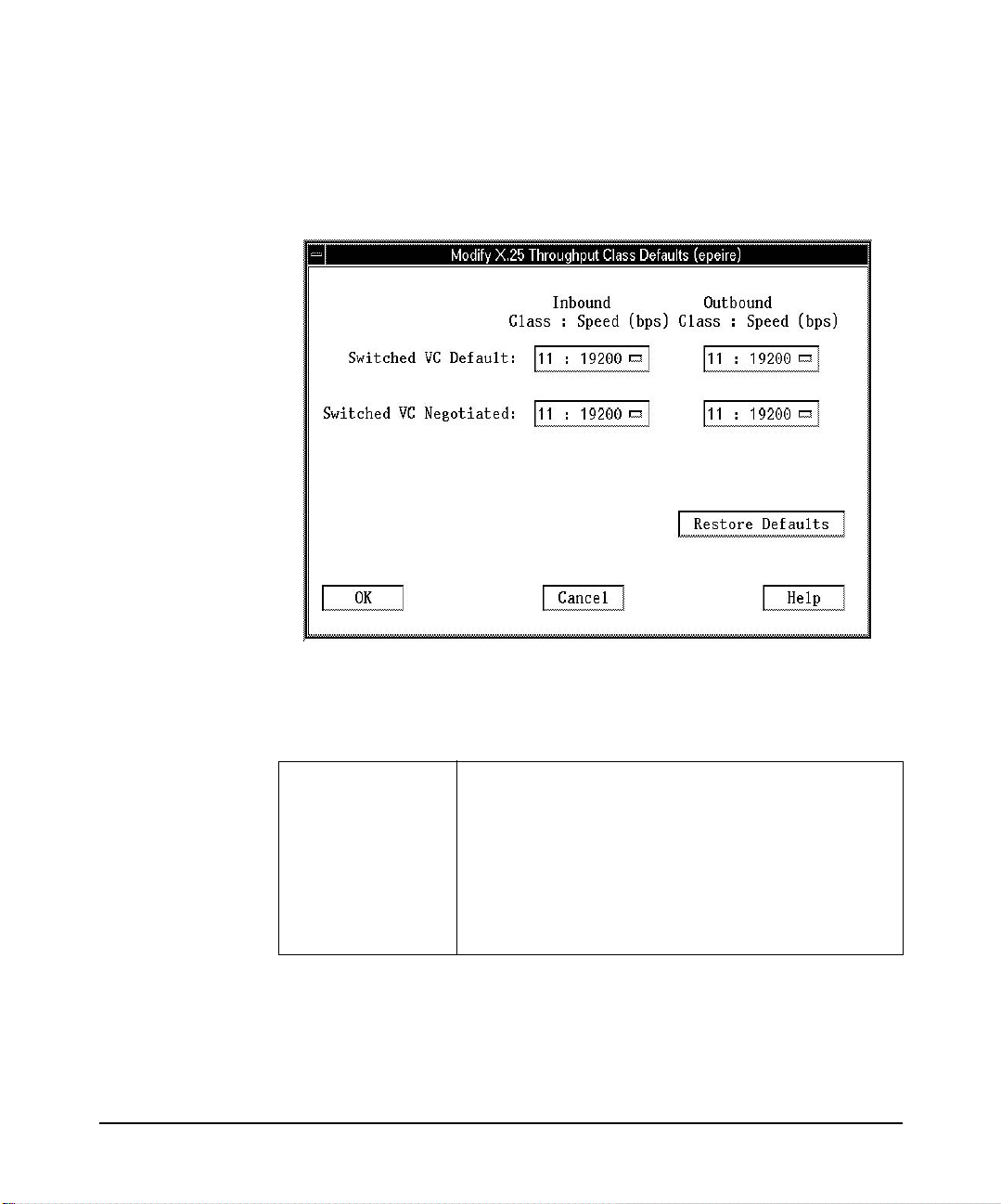
Figure 3-7
Configuration
Configuring the X.25 Link
Step 5. Click on Modify Throughput Class Settings to modify Switched and
Permanent VC throughput class settings. The following dialog appears:
Step 6. Enter or modify field values as required (refer to the field descriptions
below).
Table 3-9 Modify Throughput Class Settings Field Descriptions
Switched VC
Default: Inbound
and Outbound
CCITT class number. If Throughput Class
negotiation is disabled, this value replaces the
Switched VC Negotiated field value. The range is
3 through 13 and the default is 11. See the table
after these field descriptions listing the CCITT
class numbers and the corresponding line speed
Baud rate. Use the value given on your
subscription form.
Chapter 3 43
Page 44

Configuration
Configurin g the X.25 Link
Table 3-9 Modify Throughput Class Settings Field Descriptions
Switched VC
Negotiated:
Inbound and
Outbound
Table 3-10 Throughput Classes and Line Speeds
CCITT class number Line speed Baud rate (bps)
375
4 150
5 300
6 600
7 1200
8 2400
9 4800
CCITT class number. If Throughput Class
negotiation is enabled, this value is used as the
opening bid for outbound calls and as a counter
offer when the inbound opening bid is higher. The
range is 3 through 13, and the default is 11. See
the table below for CCITT class numbers and
corresponding line speed Baud rate. Use the
value given on your subscription form.
10 9600
11 19200
12 48000
13 64000
Step 7. Click on OK to return to the “Configure X.25 Card” window when you
have finished verifying level 3 values.
Verif yi ng L eve l 2 Val ue s
Follow the steps below to verify level 2 values:
Chapter 344
Page 45

Configuration
Configuring the X.25 Link
NOTE If you subscribe to a public network, the network provider will provide
the appropriate settings for all level 2 parameters. These settings will
differ depending on the network provider and the type of service to which
you subscribe. Refer to your Network Subscription Form for the correct
settings for your configuration.
Step 1. At the “Configure X.25 Card” window, select Verify Level 2 Values.
The following dialog appears:
Figure 3-8
Select either Modulo-8 or Modulo-128 to set the Level 2 Modulo values.
The default is Modulo-8.
The valid window-size values for Modulo-8 range from 1 to 7. For
Modulo-128, the valid window-size values range from 1 to 127.
Chapter 3 45
Page 46

Configuration
Configurin g the X.25 Link
Step 2. Enter or modify field values as required (refer to the field descriptions
below). Use the Help button to display information and instructions for
each field.
Table 3-11 Verify Level 2 Values Field Descriptions
k - Level 2
Window Size
Maximum number of frames that can be
transmitted without an acknowledgment. The
range is 1 through 7 for Modulo-8 and 1 through
127 for Modulo-128. The default is 7. Use the
value given on your subscription form.
T1 Retransmission
Timer
Maximum number of milliseconds to wait for an
acknowledgment before retransmitting a frame.
The range is 100 to 12000. The default is 3000.
Use the value given on your subscription form.
T3 - Idle Timer Maximum number of milliseconds that a line can
be idle before it is declared disconnected. This
value should be greater than or equal to the
Retransmission Timer (T1) times the
Retransmission Count (N2). The range is 1000 to
240000. The default is 60000. Use the value given
on your subscription form.
N1 - Frame Size Maximum number of octets that can be
transmitted in a single frame. The range is 149
(minimum) through 4103. The default is 149.
N2 Retransmission
Count
Maximum number of times a given frame can be
transmitted before an error condition is
identified. The range is 0 through 255. The
default is 20.
NOTE Because the timer values count the amount of time between
unacknowledged frames, you may need to increase the values of T1
(Retransmission Timer) and T3 (Idle Timer) if you use Modulo-128 with
a window size greater than seven.
Step 3. Click on OK to return to the “Configure X.25 Card” dialog when you have
finished verifying level 2 values.
Chapter 346
Page 47

Configuration
Configuring the X.25 Link
Step 4. Click on OK to complete X.25 software configuration and save your
changes. Your X.25 interface (port) should appear in the object list with
status Enabled (no problem found and link connected correctly). If not,
carefully repeat the steps in this chapter until the configuration is
enabled.
If your port is not connected to a running network, it will display as
configured.
You have completed the interface configuration.
Step 5. Select Exit from the File menu if you have no need to configure access
to other systems or to PAD services. Then exit SMH.
If you need to configure access to other systems or configure PAD
services, stay in SMH and continue with the instructions in “Configuring
Remote System Access” (to configure access to other systems) and in
“Configuring PAD Services” (to configure PAD services).
NOTE Your system will not reboot when you exit. Your configuration is effective
immediately without the need to create a new kernel.
If you want to control Services (Internet/Berkeley Services or Network
Services (NS)), refer to the documentation set for those products.
Chapter 3 47
Page 48

Configuration
Configuring Remote System Access
Configuring Remote System Access
Follow the steps below to configure access to other hosts and systems
that use TCP/IP protocol. (The procedures in this section are optional.
Your X.25 link software does not require that you configure access to
other systems).
NOTE System Administration Manager (SAM) is deprecated in the 11iv3
release of HP-UX. HP System Management Homepage (HP SMH), an
enhanced version of SAM, is introduced for managing HP-UX.
Step 1. If you have not already done so, type smh at the HP-UX prompt.
Step 2. At the SMH main window, select “Tools”. Numerous object lists are
displayed.
Step 3. At the “Networking and Communications” window, highlight Hosts and
click on OPEN. Highlight Local Hosts and click on OPEN.
SMH displays all remote system names and IP addresses that have
already been configured.
Step 4. Select Add from the Actions menu. The following dialog appears:
NOTE The appearance of the “Add Internet Connectivity” dialog may be slightly
different from the example below depending on the version of the X.25
software you are running.
Chapter 348
Page 49

Figure 3-9 Add Internet Connectivity Dialog
Configuration
Configuring Remote System Access
Step 5. Enter or modify field values as required (refer to the field descriptions
below). Use the Help button for information and instructions for each
field.
A Provide X.25 Information button may appear on this dialog
depending on the Internet address you configure. If it does, follow the
instructions in Step 6. SMH may also decide that a gateway is required,
again depending on the Internet address you configure (see the on-line
Help for more information on gateways and the gateway dialog).
Chapter 3 49
Page 50

Configuration
Configuring Remote System Access
Table 3-12 Add Internet Connectivity Field Descriptions
Internet Address Identifier by which the remote system is known
on the network. It is composed of four integers (0
to 255) separated by periods (for example,
192.2.3.6). Use the Add Aliases button to assign
one or more aliases (in alphanumeric format) to
the IP Address for easier referencing. When you
exit this field, SMH determines whether a
gateway is needed for the connection, or whether
you need to provide X.25 information for the
remote system. If the Provide X.25
Information button is displayed, follow the
instructions in Step 6 below.
Remote System
Name
Name assigned to the remote system to which you
want to connect.
Comments Use this field to add useful information about the
remote system (for example, the name and
telephone number of the user).
Step 6. If the Provide X.25 Information button is displayed, you must use it
to configure X.25 information about the remote system. When you click
on Provide X.25 Information, the following dialog appears:
Chapter 350
Page 51

Figure 3-10
Configuration
Configuring Remote System Access
Step 7. Enter or modify field values as required (refer to the field descriptions
below).
If you add more VCs to an interface in the future, you must stop the
interface with x25stop or with SMH’s Disable Card function and
restart it as an IP interface with SMH’s Enable Card function or with
the following command:
x25init -c [configuration_file]-a [ipmapfile]
Chapter 3 51
Page 52

Configuration
Configuring Remote System Access
Table 3-13 Provide X.25 Information Field Descriptions
X25 Address X.25 address (sometimes referred to as the X.121
address) of the remote system. The X.25 address
assigned by the network provider uniquely
identifies the node in an X.25 network. The
address consists of a maximum of 15 digits. You
must complete this field.
Switched VC Enable this field if a switched virtual circuit
(SVC) will be used for this connection. When
Switched VC is enabled (default), three additional
fields can be configured: Request reverse
charging, Accept reverse charging, and Closed
user group (refer to the field descriptions below).
Permanent VC Enable this field if a permanent virtual circuit
(PVC) will be used for this connection. When
Permanent VC is enabled, two additional fields
can be configured: PVC Number and Local
Programmatic Access Name.
Request reverse
charging
Enable this field if the local system will make
collect calls to the remote system. If this field is
disabled, no collect calls can be made.
Accept reverse
charging
Enable this field if you want the local system to
accept collect calls from the remote system. If this
field is disabled, no collect calls will be accepted.
Closed user group Enable this field if you subscribed to a closed user
group (CUG) and you want to use the CUG with
this connection. Do not select this item if you did
not subscribe to a CUG or if you do not want this
connection to belong to a CUG. If you enable this
field, an additional field (CUG Number) appears.
Enter the number of the CUG to be associated
with this connection.
Chapter 352
Page 53

Configuration
Configuring Remote System Access
Step 8. Click on Apply or OK. The Apply button leaves you in the current dialog
so you can configure other remote systems; the OK button returns you to
the Internet Addresses (& Routes) object list. SMH updates the
object list to include the remote system you configured regardless of
which button you used.
NOTE You can modify or remove remote systems and modify default gateways
by highlighting the Remote System Name on the object list and selecting
Modify, Remove, or Modify Default Gateway from the Actions menu.
Step 9. Select Exit from the File menu.
Remote system access for your X.25 link is now configured.
Chapter 3 53
Page 54

Configuration
Configurin g X.25 over LLC2
Configuring X.25 over LLC2
This section describes how to configure X.25 over LLC2. Configuring
X.25 over LLC2 allows X.25 layer 3 to connect to DLPI instead of LAP-B
and provides the X.25 functionality on top of LAN cards such as
Ethernet, FDDI, and TokenRing.
NOTE In this document, an XOL interface on the peer or local system is
referred to as “box”.
Configuration Files
To configure the LLC2 feature, the following configuration files must be
added or updated manually:
• Generic X.25 configuration file
• LLC2 specific configuration file
Generic X.25 Configuration file
The generic X.25 configuration file is used with a few additional XOL
specific parameters to configure X.25 over LLC2 (XOL). To support the
XOL HA feature, some of the existing parameter names are modified and
a few new parameters are introduced.
NOTE The parameters introduced in an earlier release of X.25 are supported.
However, HP recommends that you migrate to the new parameters.
Migration is required for XOL HA support.
Chapter 354
Page 55

Configuri ng X.25 over LLC2
Table 3-14 lists the XOL specific parameters that must be defined while
configuring an XOL interface.
Table 3-14 Additional XOL specific configuration parameters
Field Format Value
Configuration
device Device name
string.
Name of the LAN card
where the XOL
interface is
configured.
XOL_logical_port_id
(replaces lan_box_id)
Integer 0-n The XOL logical port
identifier for the XOL
interface on the given
LAN card.
XOL_destination_macaddr
(replaces the MAC address
in the lan_box_addr)
One
hexadecimal
value. This
value must be
The destination MAC
address to which the
XOL interface is
connected.
prefixed with
0x.
XOL_DSAP One
hexadecimal
value. This
value must be
prefixed with
0x.
The destination SAP
value of the peer XOL
interface. Set the
value of DSAP to any
even value in the
range 0x70 - 0x7e,
both inclusive.
XOL_SSAP One
hexadecimal
value. This
value must be
prefixed with
0x.
The source SAP value
of the local XOL
interface. Set the
value of SSAP to any
even value in the
range 0x70 - 0x7e,
both inclusive. If the
value for SSAP is not
provided, then SSAP
takes the value of
DSAP.
Chapter 3 55
Page 56

Configuration
Configurin g X.25 over LLC2
Table 3-14 Additional XOL specific configuration parameters (Continued)
Field Format Value
standby_device** Device name
string
XOL_floating_macaddr** One
hexadecimal
value; must be
prefixed with
0x
Name of the standby
LAN device used for
local failover. For
more details about
this parameter, see
“Configuring the High
Availability Feature
for X.25 over LLC2” on
page 81. Required
only for local failover
support.
The unique MAC
address for the LAN
card in the LAN
subnet. For more
details about this
parameter, see
“Configuring the High
Availability Feature
for X.25 over LLC2” on
page 81. Required
only for local failover
support.
** Required for HA feature
NOTE The configuration parameters may be specified in the old format.
However, HP recommends that you use the new format while specifying
the configuration parameter. XOL is not supported over APA (Auto Port Aggregation).
Following are two sample files. Example 3-1 provides a sample file that
has the old parameters in the old format. Example 3-2 provides a sample
file that has the new parameters in the new format.
Chapter 356
Page 57

Configuration
Configuri ng X.25 over LLC2
Example 3-1 Sample File with the Old Parameters in the Old Format
device lan00x7c
lan_bo x_ id 1
lan_box_addr 0x080009c4728a 0x7e
Example 3-2 Sample File with the New Parameters in the New Format
device lan0
XOL_logical_port_id 1
XOL_destination_macaddr 0x080009c4728a
XOL_DSAP 0x72
XOL_SSAP 0x7C
standb y_ dev ice lan1
XOL_fl oa tin g_macadd r 0x0060B0A4EBE5
A sample generic configuration file is available for reference. It is
available in the /etc/x25 directory and the filename is
x25init_llc2_smpl.
Specific Configuration File
This file is an X.25 over LLC2 specific configuration file and contains
information about every LAN. This file is unique to the host.
Following is the syntax of this file:
lan<#> <number of boxes>
Following is a sample configuration file:
lan0 3
lan1 1
Following is an example of an XOL configuration file that is installed in
/etc/x25 directory. Following are the assumptions: The X.121 address
of the local XOL interface is 7111 and that of the remote XOL interface is
7222.
Example 3-3 LLC2 Configuration
#
# Likely runstring: x25init -c x25init_llc2_smpl
X.121 7111 # X.121 address
Chapter 3 57
Page 58

Configuration
Configurin g X.25 over LLC2
X.121_ pa cke t '' “ # use a null (i.e. length 0) packet address
(TransPacaddressing)
name interface0 # interface name for Level 3 access
device lan0 # device to initialize
XOL_logical_port_id 0 # logical port id for lan interface
XOL_DSAP 0x7E # destination SAP id
XOL_SSAP 0x7E # source SAP id
XOL_destination_macaddr 0x080009c4728a # Remote mac address
# Follow ing nee ded only for Lo cal High Availability feature
#standby_device lan1 # standby lan card for local failover.
#XOL_floating_macaddr 0x0060B0A4EBE5 # Unique Mac address to be assigned to the
lan card before bringing the XOL interface up.
# Level 2 Par am et ers
#
t1 3000
t3 60000
framesize 149
n2 20
l2window 7
# Level 3 Par am et ers
# virtual circuit parameters
# logical channel id, start num [1-4095], type, how many
lci 1 pvc 5 # 5 permanent VCs
lci 255 ins vc 5 # 5 one-way incoming SVCs
lci 2048 svc 6 # 6 two-way switche d VCs
networ kt ype TRANSPAC # CCITT 19 84, DTE (see /etc/x25/x25_networks)
fast_s el ect enabled # allow inc om in g ca lls with call user data
reverse_charge enabled # allow incoming calls requesting reverse changes
def_inpacketsize 128 # default packetsize
def_outpacketsize 128 # default packetsize
Chapter 358
Page 59

Configuration
Configuri ng X.25 over LLC2
def_in wi ndo w 7 # default window size
def_outwindow 7 # default window size
def_in th rup utclass 19 200 # defa ul t thr uput class
def_outthruputclass 19200 # default thruput class
flowco nt rol on # flow contro l ne go ti ation allowed
neg_in pa cke tsize 128 # offere d packet size if using flow control negotiation
neg_outpacketsize 128 # offered packetsize if using flow control negotiation
neg_inwindow 7 # offered window size if using flow control negotiation
neg_outwindow 7 # offered window size if using flow control negotiation
thrupu tc las s on
neg_inthruputclass 19200 # offered thruput class if using thruput class
negotiation
neg_outthruputclass 19200 # offered thruput class if using thruput class
negotiation
pvc_in pa cke tsize 128 # pack et siz e fo r PVCs
pvc_ou tp ack etsize 128 # pack et siz e for PVCs
pvc_inwindow 7 # window size for PVCs
pvc_outwindow 7 # window size for PVCs
# IP Relate d Pa ra meters
IP 15.4.64 .1 20 255.255.248 .0 # IP address and subnet mask
mtu 1024 # max transmiss io n un it 1024 octets
hold 300 # 5 minute hold timer
idle 600 # 10 minute idle timer
NOTE For an XOL configuration, L3 packet sizes greater than 1024 are not
supported.
If the XOL interface on the host is connected to a router supporting X.25
over LLC2, the router must be configured with the correct routing
entries. For example, if an XOL interface on the host is connected to a
CISCO router and the XOL configuration on the host is identical to the
configuration in the previous example, the following configuration is
required:
Chapter 3 59
Page 60

Configuration
Configurin g X.25 over LLC2
• To enable the cmns, complete the following steps:
Step 1. Run the following command at the CISCO console:
Configure Terminal
Step 2. Run the following command at the CISCO console:
Interface fastethernet 1/0
Step 3. Run the following command at the CISCO console:
cmns enable
Step 4. Run the following command at the CISCO console:
<Ctrl+Z>
• To add routing entries to X.25 routing table, complete the following
steps:
Step 1. Run the following command at the CISCO console:
Configure Terminal
Step 2. Run the following command at the CISCO console:
x25 route ^ 7111 interface FastEthernet1/10 mac
0011.0a80.31d6
Step 3. Run the following command at the CISCO console:
x25 route ^ 7222 interface FastEthernet1/10 mac
0800.09c4.728a
Step 4. Run the following command at the CISCO console:
<Ctrl+Z>
Starting and Stopping Configuration
Starting
To initialize the x25overllc2 devices, execute the x25init command with
the -L option at the command prompt.
The syntax for execution is:
x25init -c <config_file> -L <llc2_config_file>
Chapter 360
Page 61

Configuration
Configuri ng X.25 over LLC2
config_file is the generic X.25 product configuration file and
llc2_config_file is the LLC2 specific configuration file.
A sample invocation is as shown below:
x25init -c x25init_def -L llc2_conf_def
This command is executed once per box. It can be executed with different
<x25init_llc2_sampl> file but with the same <llc2_conf_def> file.
Stopping
To stop the communication with one box, the x25stop command is
executed with the -L option.The syntax for execution is:
x25stop -d <l an#> -L <XOL_logical_port_id>
<XOL_logical_port_id> is the XOL logical port identifier for the XOL
interface on the given LAN card.
NOTE SMH support is not available for configuring X.25 over LAN(LLC2). Also,
the x25init command needs to be executed manually if the system is
rebooted.
For a detailed description of the configuration, see x25overllc2 (7). For
more information on how to configure High Availability, see “Configuring
the High Availability Feature” on page 76.
For more information on LLC2, see x25init (1M), x25stop (1M), and
x25stat (1M) manpages.
NOTE To configure a Highly Available XOL interface, See “X.25 High
Availability Configuration” on page 78.
Sample setup and Configuration
The X.25 over llc2 supports one or more XOL interfaces. Following are
the two example configurations:
Chapter 3 61
Page 62

Configuration
Configurin g X.25 over LLC2
One Lan and Two Boxes configuration
A graphical representation of the above configuration with some
arbitrary values for the MAC addresses and lan-ids is shown below:
Figure 3-11 One LAN, Two Boxes Configuration
To connect HOST to BOX 0
To implement the above configuration, the following configuration files
need to be created on the HOST system.
• Generic X.25 configuration file, x25_host_box_0
• LLC2 configuration file, llc2_lan_0
The generic X25 configuration file has to be created in the /etc/x25
directory using the example configuration file, /etc/x25/x25init_def.
Chapter 362
Page 63

The file x25_host_box_0 should contain all the mandatory level 2 and
level 3 parameters. Along with them it should contain the following
entries:
device lan 0
XOL_logical_port_id 0
XOL_destination_macaddr 0x080009411371
XOL_DSAP 0x70
XOL_SSAP 0x70
The LLC2 specific configuration file, llc2_lan_0 is created in the /etc/x25
directory with the following entries:
lan0 2
To connect HOST to BOX 1
To configure HOST to communicate with BOX1, the generic configuration file
named /etc/x25/x25_host_box_1 has be created as follows:
Apart from the mandatory level2 and level3 parameters the following
parameters have to be added:
device lan 0
XOL_logical_port_id 1
XOL_destination_macaddr 0x080009C4728A
XOL_DSAP 0x7E
XOL_SSAP 0x7E
The LLC2 specific configuration is /etc/x25/llc2_lan_0.
Configuration
Configuri ng X.25 over LLC2
To start and stop above configuration:
Starting:
Execute the following commands at the command prompt:
x25init -c x25_host_box_0 -L llc2_lan_0
Stopping:
To stop the configuration execute the following commands:
x25stop -d lan0 -L 0 # stop XOL interface with logical port id 0 on lan0
x25stop -d lan0 -L 1 # stop XOL interface with logical port id 1 on lan0
To Connect Box 0 to HOST
Chapter 3 63
Page 64

Configuration
Configurin g X.25 over LLC2
To implement the above configuration, the following configuration files need to
be created on the BOX 0.
• Generic X.25 configuration file, x25_box_0_host
• LLC2 configuration file, llc2_lan_1
The generic X25 configuration file has to be created in the /etc/x25 directory
using the example configuration file, /etc/x25/x25init_llc2_smpl.
device lan1
XOL_logical_port_id 0
XOL_destination_macaddr 0x080009DBEA7
XOL_DSAP 0x70
XOL_SSAP 0x70
The file x25_box_0_host must contain all the mandatory level 2 and level 3
parameters. Along with them it should contain the following entries:
The LLC2 specific configuration file, llc2_lan_1 is created in the /etc/x25
directory with the following entries:
lan1 1
To start and stop above configuration:
Starting:
Execute the following commands at the command prompt:
x25init -c x25_box_0_host -L llc2_lan_1
Stopping:
To stop the configuration execute the following commands:
x25stop -d lan1 -L 0 # stop XOL interface with logical port id 0 on lan1
To Connect Box 1 to HOST
To implement the above configuration, the following configuration files need to
be created on the BOX 1.
• Generic X.25 configuration file, x25_box_1_host
• LLC2 configuration file, llc2_lan_2
The generic X25 configuration file has to be created in the /etc/x25 directory
using the example configuration file, /etc/x25/x25init_llc2_smpl.
The file x25_box_1_host must contain all the mandatory level 2 and level 3
parameters. Along with them it must contain the following entries:
Chapter 364
Page 65

Configuri ng X.25 over LLC2
device lan2
XOL_logical_port_id 0
XOL_destination_macaddr 0x080009DBEA7
XOL_DSAP 0x7E
XOL_SSAP 0x7E
The LLC2 specific configuration file, llc2_lan_2 is created in the /etc/x25
directory with the following entries:
lan2 1
To start and stop above configuration:
Starting:
Execute the following commands at the command prompt:
x25init -c x25_box_1_host -L llc2_lan_2
Stopping:
To stop the configuration execute the following commands:
x25stop -d lan2 -L 0 # stop XOL interface with logical port id 0 on lan2
Configuration
Configuring Two Lans, with One Box Per Lan
A graphical representation of the above configuration with some
arbitrary values for the MAC addresses and lan-ids is as shown:
Chapter 3 65
Page 66

Configuration
Configurin g X.25 over LLC2
Figure 3-12 Two Lans, One Box per Lan configuration
To Configure Host to LAN0 to Box0
To configure the Host to LAN 0, BOX 0 communication the following
configuration files need to be created.
• Generic X.25 configuration file, x25_lan_0_box_0
• LLC2 configuration file, llc2_lan_0_lan_1
The x25_lan-0_box_0 file will contain all the level 3 and level2
parameters. It also contains the following entries:
device lan0
XOL_logical_port_id 1
XOL_destination_macaddr 0x080009411371
XOL_DSAP 0x70
XOL_SSAP 0x70
Chapter 366
Page 67

The LLC2 configuration file, llc2_lan_0_lan_1 will have the following
entires:
lan0 1
lan1 1
To configure Host to LAN 1 to BOX 1
To configure the Host to LAN 1 to BOX 1communication, the following
configuration file need to be created.
• X.25 generic configuration file, x25_lan_1_box_1
• LLC2 configuration file, llc2_2_lan_0_lan_1
The x25_lan_1_box_1 file is created in the /etc/x25 directory. It will
contain all the level 2 and level 3 parameters. It will also contain the
following entries:
device lan1
XOL_logical_port_id 1
XOL_destination_macaddr 0x080009C4728A
XOL_DSAP 0x7E
Configuration
Configuri ng X.25 over LLC2
XOL_SSAP 0x7E
There is only one LLC2 specific configuration file per Host. The file is
llc2_lan_0_lan_1.
To Start and Stop above configuration:
Starting:
After reconfiguring the kernel of the two boxes execute the following
commands at the command prompt:
x25init -c x25_lan_0_box_0 -L llc2_lan_0_lan_1
x25init -c x25_lan_1_box_1 -L llc2_lan_0_lan_1
Stopping:
To stop the configuration, execute the following commands at the
command prompt:
xstop -d lan0 -L 1 # stop XOL interface with logical port id 1 on lan0
xstop -d lan1 -L 1 # stop XOL interface with logical port id 1 on lan1
To Connect Box 0 to HOST
Chapter 3 67
Page 68

Configuration
Configurin g X.25 over LLC2
To implement the above configuration, the following configuration files
need to be created on the BOX 0.
• Generic X.25 configuration file, x25_box_0_host.
• LLC2 configuration file, llc2_lan_2
The generic X25 configuration file has to be created in the /etc/x25
directory using the example configuration file,
/etc/x25/x25init_llc2_smpl.
The file x25_box_0_host must contain all the mandatory level 2 and level
3 parameters. Along with them it must contain the following entries:
device lan2
XOL_logical_port_id 0
XOL_destination_macaddr 0x080009DBEA7
XOL_DSAP 0x70
XOL_SSAP 0x70
The LLC2 specific configuration file, llc2_lan_2 is created in the /etc/x25
directory with the following entries:
lan2 1
To start and stop above configuration:
Starting:
Execute the following commands at the command prompt:
x25init -c x25_box_0_host -L llc2_lan_2
Stopping:
To stop the configuration execute the following commands:
x25stop -d lan2 -L 0 # stop XOL interface with logical port id 0 on lan2
To Connect Box 1 to HOST
To implement the above configuration, the following configuration files
need to be created on the BOX 1.
• Generic X.25 configuration file, x25_box_1_host.
• LLC2 configuration file, llc2_lan_3
Chapter 368
Page 69

The generic X25 configuration file has to be created in the /etc/x25
directory using the example configuration file,
/etc/x25/x25init_llc2_smpl.
The file x25_box_0_host should contain all the mandatory level 2 and
level 3 parameters. Along with them it should contain the following
entries:
device lan3
XOL_logical_port_id 0
XOL_destination_macaddr 0x080009DBEA7
XOL_DSAP 0x7E
XOL_SSAP 0x7E
The LLC2 specific configuration file, llc2_lan_2 is created in the /etc/x25
directory with the following entries:
lan3 1
To start and stop above configuration:
Starting:
Configuration
Configuri ng X.25 over LLC2
Execute the following commands at the command prompt:
x25init -c x25_box_0_host -L llc2_lan_3
Stopping:
To stop the configuration execute the following commands:
x25stop -d lan3 -L 0 # stop XOL interface having logical port id 0 on lan3
Troubleshooting LLC2 Configuration
Symptom: Unable to connect to the remote node.
Causes:
• Hardware address of the remote node is wrongly configured in the
configuration file.
• The SAP value is incorrectly configured.
• The LCI value is incorrectly configured.
Action:
Chapter 3 69
Page 70

Configuration
Configurin g X.25 over LLC2
• Check the remote node’s hardware address using lanscan. Use the
• If the nodes are connected back to back, check if the SAP’s are
• If the nodes are connected back to back and one of the machines is
same hardware address in the generic X.25 configuration file. If you
modify the hardware address to correct the error then, re-initialize
the card using x25init.
identical for both the nodes in the generic X.25 configuration file.
configured for inbound connections only and the other machine is
configured for outbound connections only then, the starting LCI for
both the nodes must be identical in the generic X.25 configuration
file.
Chapter 370
Page 71

Configuration
Configuring PAD Services
Configuring PAD Services
This section contains step-by-step instructions for configuring PAD
services. Skip this section if you don’t need to configure PAD services.
The procedures in this section are optional. Your X.25 link software does
not require you to configure PAD services.
You can use SMH to add or modify the following:
• PAD terminal emulation (local to remote)
• PAD support server (remote to local)
• PAD printer server
• PAD UUCP server
• X.3 sets of parameters
See Chapter 6, PAD Services, for detailed reference information on PAD
services.
This section assumes that SMH is running and that you are starting
from the main window. If this is not the case, type smh at the HP-UX
prompt before continuing.
Remember to use the Help button (in the SMH window) to display
information and instructions for the content of each field.
Add/Modify PAD Terminal Emulation (Local to Remote)
Follow the steps below to add or modify PAD terminal emulation for a
remote system:
Step 1. At the SMH main window, highlight “Networking and Communications”
and select Open Item from the Actions menu.
Step 2. At the “Networking and Communications” window, highlight X.25 PAD
Services and select Open Item from the Actions menu.
Step 3. Highlight Terminal Emulator and select Open Item from the Actions
menu.
Chapter 3 71
Page 72

Configuration
Configuring PAD Services
SMH displays an object list that shows all remote systems currently
configured for PAD terminal emulation.
Step 4. Select Add from the Actions menu to configure PAD terminal emulation
for an unlisted remote system, or highlight a remote system from the list
and select Modify.
Step 5. Enter or modify field values as required.
Step 6. Click on Apply to apply the new settings and to add additional system
connections. Click on OK to save changes and exit this dialog.
Step 7. Select Exit from the List menu to return to the “X.25 PAD Services”
dialog.
NOTE If you enabled Reverse Charge Requested, you must also configure the
PAD support server. See “Add/Modify PAD Support Server (Remote to
Local)” for step-by-step instructions for configuring the PAD support
server.
Step 8. Select the next PAD service you need to configure from the list on the
“X.25 PAD Services” dialog.
Add/Modify PAD Support Server (Remote to Local)
Follow the steps below to add or modify a PAD support server for a local
terminal or system:
Step 1. At the SMH main window, highlight “Networking and Communications”
and select Open Item from the Actions menu.
Step 2. At the “Networking and Communications” window, highlight X.25 PAD
Services and select Open Item from the Actions menu.
Step 3. Highlight Support Server and select Open Item from the Actions
menu.
SMH displays an object list that shows all terminals/systems currently
configured for access via X.25.
Step 4. Select Add from the Actions menu to configure a terminal/system that is
not listed for access via X.25, or highlight a terminal/system from the list
and select Modify.
Chapter 372
Page 73

Configuration
Configuring PAD Services
Step 5. Enter or modify field values as required.
Step 6. Click on Apply to apply the new settings and to add additional PAD
support servers. Click on OK to save changes and exit this dialog.
Step 7. Select Exit from the List menu to return to the “X.25 PAD Services”
dialog.
Step 8. Select the next PAD service you need to configure from the list on the
“X.25 PAD Services” dialog.
Add/Modify PAD Printers Server
Follow the steps below to add or modify remote PAD printers:
Step 1. At the SMH main window, highlight “Networking and Communications”
and select Open Item from the Actions menu.
Step 2. At the “Networking and Communications” window, highlight X.25 PAD
Services and select Open Item from the Actions menu.
Step 3. Highlight Printers Server and select Open Item from the Actions
menu.
SMH lists all remote printers that your system can currently access via
X.25.
Step 4. Select Add from the Actions menu to configure access to an unlisted
remote printer, or highlight a remote printer from the list and select
Modify.
Step 5. Enter or modify field values as required.
Step 6. Click on Apply to apply the new settings and to add additional PAD
printers. Click on OK to save changes and exit this dialog.
Step 7. Select Exit from the List menu to return to the “X.25 PAD Services”
dialog.
Step 8. Select the next PAD service you need to configure from the list on the
“X.25 PAD Services” dialog.
Add/Modify UUCP Server
Follow the steps below to add or modify a UUCP server:
Chapter 3 73
Page 74

Configuration
Configuring PAD Services
Step 1. At the SMH main window, highlight “Networking and Communications”
and select Open Item from the Actions menu.
Step 2. At the “Networking and Communications” window, highlight X.25 PAD
Services and select Open Item from the Actions menu.
Step 3. Highlight UUCP Server and select Open Item from the Actions menu.
SMH lists all remote systems currently configured for X.25 PAD UUCP
connectivity.
Step 4. Select Add from the Actions menu to configure PAD UUCP connectivity
for an unlisted remote system, or highlight a remote system from the list
and select Modify.
Step 5. Enter or modify field values as required.
Step 6. Click on Apply to apply the new settings and to add additional PAD
UUCP connections. Click on OK to save changes and exit this dialog.
Step 7. Select Exit from the List menu to return to the “X.25 PAD Services”
dialog.
Step 8. If necessary, select the next PAD service you need to configure from the
list.
In order for PAD UUCP connectivity to function correctly, UUCP must
also be configured. If you have not already done this, you can configure
UUCP by returning to the “Networking and Communications” window,
highlighting UUCP and selecting Open Item from the Actions menu.
From this dialog you can configure UUCP Devices and/or UUCP Remote
Systems (see the on-line Help or UUCP documentation for more
information).
Add/Modify X.3 Parameters
Follow the steps below to add or modify X.3 parameters. Refer to
Chapter 6, PAD Services, for detailed descriptions of the X.3 parameters.
Chapter 374
Page 75

Configuration
Configuring PAD Services
NOTE The X.3 values that you configure here are initially downloaded to the
PAD. As the terminal characteristics of your session change, the X.25
software automatically downloads new values for certain parameters. Do
not be alarmed if the values of some parameters are different from the
values you initially specified.
Step 1. At the SMH main window, highlight “Networking and Communications”
and select Open Item from the Actions menu.
Step 2. At the “Networking and Communications” window, highlight X.25 PAD
Services and select Open Item from the Actions menu.
Step 3. Highlight X.3 Sets of Parameters and select Open Item from the
Actions menu.
SMH displays an object list showing all X.3 sets or profiles currently
configured.
Step 4. Select Add from the Actions menu to configure an unlisted X.3 set, or
highlight an X.3 set from the list and select Modify.
When you select Add, SMH displays the “Set X.3 Default Values” dialog.
This dialog lets you set defaults for PAD terminal emulation, PAD
support server, PAD printers server, or PAD UUCP server.
Step 5. Enter or modify field values as required. Click on Help for information
and instructions for each field. A full description of X.3 parameters are
provided in Chapter 6, “PAD Services.”
Step 6. Click on Apply to apply the new settings and to add additional X.3 sets.
Click on OK to save changes and exit this dialog.
Step 7. Select Exit from the List menu.
Chapter 3 75
Page 76

Configuration
Configuring the High Availability Feature
Configuring the High Availability Feature
The X.25 link software provides integration of the X.25/Streams solution
to the High Availability HP MC/ServiceGuard feature on HP 9000 Series
800 Systems, allowing local and remote failure recovery.
This feature requires that the HP MC/ServiceGuard product (B3936AA)
has been installed and that the X.25 software uses switches that support
Hunt Group Facility allowing multiple DTEs to share a common X.121
address.
You should be familiar with the HP MC/ServiceGuard product prior to
installation. For more information on Serviceguard, see Managing
MC/ServiceGuard.
The High Availability features include:
• Local Failure: Support of local failure for an X.25 link is provided
by a PDN using existing X.25 functionality. If a local X.25 PSI card
fails, the calling DTE will see the link go down.
The Hunt Group facility results in all incoming calls being directed
to the remaining “good” X.25 PSI card in the system.
• Remote Failure: HP MC/ServiceGuard, uses the x25ifstate
command to monitor the X.25 status. If the monitor detects that the
X.25 link it is monitoring has gone down, all it has to do is exit.
HP MC/ServiceGuard detects that the monitor service belonging to
the package has disappeared, stops the package, and starts the
migration towards a second system.
The X.121 address of the first package is taken over by the second
system from the X.25 configuration file.
Chapter 376
Page 77

Configuration
Configuring the High Availability Feature
X.25 Cluster Definition
To configure a High Availability cluster, use SMH to define all cluster
systems by giving their:
NODE_NAME
NETWORK_INTERFACE
HEARTBEAT_IP
X.25 Commands to be Configured in High Availability Pack ages
Start X.25 link
x25init -c x25config -a ipmap -d x25dev (see x25init (1m))
Stop X.25 link
x25stop -d x25dev (see x25stop (1m))
Monitor X.25 link
x25ifstate -d x25dev -H (see x25ifstate (1m))
X.25 Package Definition
An X.25 package is needed for each HA X.25 node. This package allows
HP MC/ServiceGuard to automatically:
• start the X.25 link (x25init command) when the X.25 package starts
• start a process (x25ifstate command) to monitor the state of the
X.25 link
• stop the failed X.25 package before migrating to a backup node
To define each X.25 package, you need:
Package N ame:
to identify the X.25 package. Use a name such as
x25pkg1.
Service Name:
to monitor the X.25 link to be managed
Service Command:
Chapter 3 77
Page 78

Configuration
Configuring the High Availability Feature
Package Control Script Location:
X.25 High Availability Configuration
General So lu ti on for Loc a l and R em ot e Failover
to monitor the X.25 link status. It could be either a
script based on x25ifstate or the x25ifstate
command directly, depending on your configuration.
location of the script to start/stop the X.25 link and
execute the service(s).
Package A
Hunt Group
PKG A
Client
PKG B
Client
X.25PDN
Connections
Package B
Hunt Group
Connections
Alternate
Connections
(Idle)
X.25
switch
DTE
PKG
A
DTE
PKG
B
Package B
Package B
DTE
PKG
B
if package A
fails on system
1, system 2
takes over
package A
DTE
PKG
A
B
when package
A is functional
on system 1,
system 2 is on
standby for
package A
DTE
PKG
A
Package A
DTE
PKG
A
X.25
switch
DTE
PKG
B
DTE
PKG
Example 3-4 One EXAMPLE of Remote Failure
The only file that contains the X.25 commands to run for High
Availability is the /etc./cmcluster/pkg*/control.sh file (one per
X.25 package).
# SERVICE NAMES AND COMMANDS
SERVIC E_ NAM E [0] =pkg1. Service_Name_01 (same SERVICE_NAME as in pkg co nf)
SERVICE_CMD [0] =”/usr/sbin/x25ifstate -d /dev/x25_1 -H -t 5”
SERVICE_RESTART [0] = “ “
#add below the service names which define the applications that rely on the X.25
card
Chapter 378
Page 79

Configuration
Configuring the High Availability Feature
# e.g.# SER VI CE _NAME [1] = <ot her name>
# SERVICE_CMD [1] = <other monitor>
# START OF CU ST OM ER DEFINED FU NCTIONS
function customer_defined_run_cmds
{
#ADD customer defined run commands
: # do nothing instruction, because a function must contain at least one command.
x25ini t -c /e tc /x25/x25 config_1 -a /etc/x25/ip_to_x121_map
sleep 5
test_return 51
}
function customer_defined_halt_cmds
{
#ADD customer defined halt commands
: # do nothin g in st ruction, be cause a function must contain some command.
#stopping the specific X.25 card means the signal modem will be down
x25sto p -d /d ev /x25_1
test_return 52
}
Checking the Configuration
Check that your configuration is correct using x25server, x25check,
and ping.
x25server Run the x25server command. This starts a background
process that waits for packets from an x25check command and sends a
reply.
x25check Execute the x25check command, using your X.121 address:
$ x25c he ck 25 0207
X25CHE CK (c) CO PYRIGHT Hew lett-Packard Company 1988.
Test Starts on .. Wed Dec 8 09:15:01 1993
Initialization of the test...
CALL packet sent ...
The following figures have been measured on the network:
Set up time : 26 7 ms
Remote Connection Succeeded
Execute the x25check command again, but this time with data packets:
Chapter 3 79
Page 80

Configuration
Configuring the High Availability Feature
$ x25check 250207 -s 32 -n 1
X25CHE CK (c) CO PYRIGHT Hew lett-Packard Company 1988.
Test Starts on .. Wed Dec 8 09:15:47 1993
Initialization of the test...
CALL packet sent ...
DATA pac ket sen t ... DATA pack et received
The following figures have been measured on the network:
Set up time : 286 ms
Transi t tim e : 24 5 ms
Remote Connection Succeeded
If your system has multiple X.25 cards, you may need to specify the
particular interface in order for x25check to work properly. For example,
to run x25check on the second port of the first card (interface x25_0p2),
you would use the following format:
x25check 250207 -i interface0p2
ping command Run the ping command to check your IP over X.25
connection. You can use either an IP address, or the alias for the local
node (defined in the hosts file). The following example sends 6 packets of
100 bytes:
ping hpi ndl a 10 0 -n 6
PING hpindla: 100 byte packets
100 byte s fro m 15 .128.131. 152: icmp_seq=1. time=321. ms
100 byte s fro m 15 .128.131. 152: icmp_seq=2. time=320. ms
100 byte s fro m 15 .128.131. 152: icmp_seq=3. time=319. ms
100 byte s fro m 15 .128.131. 152: icmp_seq=4. time=318. ms
100 byte s fro m 15 .128.131. 152: icmp_seq=5. time=320. ms
100 byte s fro m 15 .128.131. 152: icmp_seq=6. time=321. ms
--hpindla PING Statistics-6 packets transmitted, 6 packets received, 0% packet loss
round- tr ip (m s) min/avg /max = 318/319/321
You can then check your IP over X.25 connection to a remote host using
its IP address or alias.
If ping does not run successfully on the local node address, refer to
Chapter 8, “Troubleshooting.”
Chapter 380
Page 81

Configuration
Configuring the High Availability Feature f or X.25 over LLC2
Configuring the High Availability Feature for
X.25 over LLC2
This section describes how to configure the local and remote failover
features for X.25 over LLC2 (XOL) interface. It also describes the local,
remote, and a combination of local and remote failover.
WARNING The failover is not transparent and results in loss of data and
existing connections. After a failover, the XOL connections must
be re-established.
Unique MAC Address Requirement
XOL High Availability (XOL HA) is based on sharing a unique MAC
address for the primary and standby LAN cards, whichever is active. The
use of a unique MAC address makes the card swap transparent from the
XOL router side or peer system, which sees the same MAC address
associated with the active interface.
NOTE To avoid MAC address collision, the system administrator must identify
an unused, unique MAC address in their LAN subnet. The lanadmin
command is used to change the MAC address of the card. After failover,
the failed LAN card is reconfigured with its factory default MAC
address. XOL is not supported over APA (Auto Port Aggregation).
Before you run the lanadmin command to set up the unique MAC
address, you may test whether the MAC address chosen by you is
selected by running the linkloop command. For more information, see
linkloop (1m). The uniqueness of the MAC address is verified on the
LAN cards currently active in the LAN segment. The linkloop
command sends an OK message if the MAC address is already in use.
Chapter 3 81
Page 82

Configuration
Configuring the High Availability Feature for X.25 over LLC2
NOTE The routing table of the router connected to the host system must be
updated with the unique MAC address identified by the user. If the XOL
router supports the Hunt Group facility for XOL HA, the unique MAC
address may not be required to achieve the HA functionality for XOL
interface. For more information on Hunt Group facility, see “Configuring
the High Availability Feature for X.25 over LLC2” on page 81.
WARNING When several highly available XOL interfaces are configured on
a given LAN card, failover of all the highly available XOL
interfaces to the standby LAN card occurs immediately after one
XOL interface fails. This is because the same unique MAC
address is used by all XOL interfaces on the given LAN card.
Local Failover
NOTE You need not install ServiceGuard for Local failover.
For local failover to happen, you must define a standby LAN card in the
X.25 configuration file. The primary X.25 configuration file is used to
configure the XOL interface on the standby LAN card after the local
failover. As a result, the standby LAN card inherits all the configuration
parameters from the primary interface, including the XOL logical port-id
(also called box-id). The XOL interface starts first on the primary LAN
card. If this XOL interface fails, an attempt is made to restart it on the
standby LAN card. If the XOL interface fails on the standby LAN card,
an attempt is made to failover back to the primary LAN card. This
failover succeeds only if the primary LAN card is back UP and
operational. Otherwise, the XOL interface goes down.
For more information on how to use this local failover functionality, see
“Configuring XOL HA for Local Failover Without ServiceGuard” on
page 83.
Chapter 382
Page 83

Configuring XOL HA for Local Failover Without ServiceGuard
In Figure 3-13, system A has two LAN cards, namely, lan0 (the primary
LAN card) and lan1 (the standby LAN card). The standby LAN card
provides local failover for the XOL interface with X.121 address 1111.
The user supplied, unique MAC address that is specified in the XOL
configuration file as a value for the field XOL_floating_macaddr, for that
LAN segment is uMAC.
The XOL interface with X.121 address 1111 is brought up on lan0 on
system A (uMAC is automatically assigned to lan0 on system A when the
XOL interface is initialized).
Figure 3-13 Before the Failover
Configuration
Configuring the High Availability Feature f or X.25 over LLC2
When the lan0 (the primary LAN card) fails, the XOL interface stops on
lan0, and a XOL interface is brought up automatically on lan1 (the
standby LAN card on system A) using the same configuration file. An
attempt is made to configure lan0 with the factory default MAC address,
and uMAC is assigned to lan1 on system A during the local failover. The
Chapter 3 83
Page 84

Configuration
Configuring the High Availability Feature for X.25 over LLC2
X.25 connection must be re-established on the XOL interface. When the
card lan0 comes up later, it is configured with the factory default MAC
address.
Figure 3-14 After the Failover
To configure XOL local failover, complete the following steps:
NOTE The XOL HA feature is enabled by default in HP-UX 11i v3.
Therefore, the -enableXOLHA option is no
longer required.
Chapter 384
Page 85

Configuration
Configuring the High Availability Feature f or X.25 over LLC2
Step 1. T
NOTE Local failover is automatically enabled by defining a standby_device in
Example 3-5 Configuring Standby Device and Unique MAC Address
o configure the standby device and the unique MAC address in the
nfiguration file of the XOL primary interface, modify the following
co
syntax:
Standby_device <standby LAN card name> # used for local
failover
XOL_floating_macaddr <unique MAC address>
the configuration file. If you do not require the local failover feature for
this interface, you must de-configure the standby_device by removing or
commenting the line in the configuration file. The standby XOL interface
inherits the configuration of the primary XOL interface during failover
because the same configuration file is used to configure the XOL
interface.
If the asumptions in the XOL configuration file are the following:
• The primary LAN card is lan0
• The standby LAN card is lan1
• The MAC address is 0x0060B0A4EbE5
Then, the XOL HA parameters take the following values:
standb y_ dev ice lan1
XOL_fl oa tin g_macadd r 0x0060B0A4EBE5
NOTE In the event of a failover, the XOL_floating_macaddr is moved from the
primary LAN card to the standby LAN card. HP recommends that you
use the primary and standby LAN cards only for the XOL links
configured with HA feature.
Step
2. To initialize the XOL HA interface with local failover support, run the
fo
llowing command:
Chapter 3 85
Page 86

Configuration
Configuring the High Availability Feature for X.25 over LLC2
x25init -c <XOL_config_file> -L <llc2_conf_def>
Remote Failover
NOTE Remote failover, with or without local failover, requires the installation
of the ServiceGuard product on the system. For more information on HP
MC/ServiceGuard product, see Managing MC/ServiceGuard document.
In the ServiceGuard cluster, the remote failover works between LAN
cards on different nodes. Each LAN card has an XOL interface which is
defined by the same configuration filename used in the SG package. The
x25ifstate command monitors the XOL interface status. When the
XOL interface fails, the x25ifstate command exits. HP MC/Service
Guard detects that the monitor service belonging to the package has
exited and stops the package. HP MC/Service Guard then starts the
same package on the standby node of the ServiceGuard cluster, which
starts the XOL interface on the LAN card on the standby node.
For more information on using the remote failover functionality with
Service Guard, see “Configuring XOL HA for Remote Failover Using
Service Guard (SG)” on page 86.
Configuring XOL HA for Remote Failover Using Service Guard (SG)
In Figure 3-15, primary system A and standby system B are part of the
SG cluster and provide remote failover of an XOL interface with X.25
address 1111. The unique, user supplied MAC address is uMAC for that
LAN segment. It is initially assigned to the card lan0 on primary system
A.
Chapter 386
Page 87

Figure 3-15 Before the Failover
Configuration
Configuring the High Availability Feature f or X.25 over LLC2
If the SG package for XOL detects an error in the XOL interface, the
package is stopped on the primary system and the equivalent package
starts on the standby system. When the SG package is stopped on system
A, the XOL interfaces (and optionally applications) on the failed LAN
card are stopped. An attempt is made to configure LAN card on system A
with the factory default MAC address. When the SG package starts on
system B, the LAN card on system B is configured with the unique MAC
(uMAC) address, and the XOL interfaces (and optionally applications)
starts on it. When the failed LAN card on system A comes up later, it is
configured with the factory default MAC address.
Chapter 3 87
Page 88

Configuration
Configuring the High Availability Feature for X.25 over LLC2
Figure 3-16 After the Failover
XOL Cluster Definition
You must define the cluster by providing the system names that are part
of SG cluster.
X.25 Commands Used in the SG Package Control Scripts:
• To set the MAC address, run the following command:
lanadmin -A <MAC address> <PPA>
• To start XOL interface, run the following command:
x25init -c /etc/x25/x25config_llc2 -L
/etc/x25/llc2_conf_def
• To monitor the XOL interface, run the following command:
x25ifstate -d /dev/x25_0l1 -H
• To stop the XOL interface, run the following command:
Chapter 388
Page 89

Configuration
Configuring the High Availability Feature f or X.25 over LLC2
x25stop -d /dev/x25_0l1
XOL Package Definition
An XOL SG package is required to configure a highly available XOL
interface on all nodes in the SG cluster. This package allows HP
MC/Service Guard to automatically:
• Assign a unique MAC address (using the lanadmin command) to the
LAN card in use.
• Start the X.25 link (x25init command) when the X.25 package
starts.
• Run the command x25ifstate to monitor the state of the XOL
interface.
• Stop the XOL interface when the monitoring command detects a
failure.
To define the X.25 package, you require the following attributes:
Package Name Identifies the X.25 package, for example, xol_pkg1.
Service Name Monitors the XOL interface to be managed, for
example, xol_SG_service1
Service Command Monitors the XOL interface status, for example,
x25ifstate
To configure XOL remote failover, complete the following steps:
NOTE The XOL HA feature is enabled by default in HP-UX 11i v3.
Therefore, the -enableXOLHA option is no
Chapter 3 89
longer required.
Page 90

Configuration
Configuring the High Availability Feature for X.25 over LLC2
NOTE When the XOL interface goes down, the service command (x25ifstate)
exits. The SG performs a package failover to the standby node configured
in the SG cluster.
The SG package file that contains the X.25 commands is
/etc./cmcluster/pkg*/control.sh file (one per XOL package).
Following is a sample SG package file:
Example 3-6 XOL SG package for remote failover
# SERVICE NAMES AND COMMANDS
SERVIC E_ NAM E [0] =pkg1. Service_Name_01 (same SERVICE_NAME as in pkg co nf)
SERVICE_CMD [0] ="/usr/sbin/x25ifstate -d /dev/x25_0l1 -H "
SERVICE_RESTART [0] = " "
# Unique MAC ad dr ess in the subn et (LAN segment), which is
# not in use. This will be the Active MAC address on the
# active node in th e cluster.
Suppli ed _MA C = 0x0060B0 A4EBE5
# START OF CU ST OM ER DEFINED FU NCTIONS
function customer_defined_run_cmds
{
# START of cu st om er defined ru n commands.
/usr/sbin/x25stop -d /dev/x25_0l1
sleep 2
/usr/s bi n/l anadmin -A $Supplied_MAC 0
/usr/s bi n/x 25init -c /e tc/x25/x25config_llc2_1 -L /etc/x25/llc 2_conf_def
sleep 5
test_return 51
# END of cust om er defined run co mmands
Chapter 390
Page 91

Configuring the High Availability Feature f or X.25 over LLC2
}
function customer_defined_halt_cmds
{
# START of cu st om er defined ha lt commands.
/usr/sbin/x25stop -d /dev/x25_0l1
Sleep 2
test_return 52
# END of cust om er defined halt commands
}
Remote Failover with Local Failover Support Using Service Guard
This is a combination of local failover and remote failover. For
information on the local and remote failovers, see “Configuring XOL HA
for Local Failover Without ServiceGuard” on page 83 and “Configuring
XOL HA for Remote Failover Using Service Guard (SG)” on page 86. If
the interface cannot be activated on either the primary or the standby
LAN card at a given time on the local node, the SG package initiates the
remote failover to the LAN card on the standby node in the SG cluster.
Configuration
NOTE On any given LAN card, the combination of highly available and not
highly available XOL interfaces is not supported. Either all or none of
the interfaces must be configured with HA (for local or remote failover)
on any given LAN card. This is because the same unique MAC address is
used by all XOL interfaces on the given LAN card.
To support remote failover with local failover, complete the following
steps:
Chapter 3 91
Page 92

Configuration
Configuring the High Availability Feature for X.25 over LLC2
NOTE Enabling or disabling of HA feature for XOL interface is system wide.
Before enabling or disabling the HA feature on a system, all existing
XOL interfaces must be stopped. The XOL HA feature is enabled by default on 11i v3.
Step
1. To configure the standby device and the unique MAC address in the
co
nfiguration file of the XOL primary interface, modify the following
syntax:
Standby_device <standby LAN card name> # used for local
failover
XOL_floating_macaddr <unique MAC address>
NOTE Local failover is automatically enabled if a “standby_device” is defined in
the configuration file. If you do not want the local failover feature for this
interface, you must de-configure the standby_device by removing or
commenting the line in the configuration file. The XOL interface inherits
the configuration of the primary XOL interface during failover because
the same configuration file is used to configure the XOL interface.
Example 3-7 Configuring Standby Device and Unique MAC Address
If the assumptions in the XOL configuration file are the following:
• The primary LAN card is lan0
• The standby LAN card is lan1
• The MAC address is 0x0060B0A4EbE5
Then, the above parameters take the following values:
standb y_ dev ice lan1
XOL_fl oa tin g_macadd r 0x0060B0A4EBE5
Chapter 392
Page 93

Configuration
Configuring the High Availability Feature f or X.25 over LLC2
NOTE In the event of a failover, the XOL_floating_macaddr is moved from the
Primary LAN card to the standby LAN card. HP recommends that you
use the primary and standby LAN cards only for the XOL links
configured with HA feature.
Step 2. Con
NOTE The x25HAmonitor command helps in failover of the XOL interface
3. To start the SG package, run the following command
Step
figure the SG package. For information on achieving remote failover
ctionality, see “XOL Package Definition” on page 89.
fun
For remote failover with local failover support, define the XOL package
with the following changes:
• In the Start script of the package, stop the monitor if it is running.
For details, see Example 3-6 on page 90.
• In the XOL package definition, use x25HAmonitor command instead
of x25ifstate as the service command, as follows:
x25HAmonitor -c /etc/x25/x25config_llc2 -L
/etc/x25/llc2_conf_def -m
between the primary and standby LAN cards (on the local system), if the
LAN card (either primary or standby) on which the XOL interface was
active fails. The x25HAmonitor exits if it is does not start the XOL
interface on the local system on either the primary or standby LAN card.
The SG does a package failover to the standby node configured in the SG
cluster.
unpkg -v <package name>
cmr
Example 3-8 Remote Failover with Local Failover support
The following two entries must be added to the LLC2 configuration file:
standby_device lan2 # lan2 is standby LAN.
XOL_fl oa tin g_macadd r 0x0060B0A4EBE5 # Unique MAC address in the subnet
The SG package file that contains the X.25 commands is
/etc./cmcluster/pkg*/control.sh file (one per XOL package).
Chapter 3 93
Page 94

Configuration
Configuring the High Availability Feature for X.25 over LLC2
# SERVICE NAMES AND COMMANDS
SERVIC E_ NAM E [0] =pkg1. Service_Name_01 (same SERVICE_NAME as in pkg co nf)
SERVICE_CMD [0] ="/usr/sbin/x25HAmonitor -c x25config_llc2 -L llc2_conf_def -m "
SERVICE_RESTART [0] = " "
# Unique MAC ad dr ess in the subn et (LAN segment) which is not in use. This will
be the Active MAC address on the active node in the cluster.
Suppli ed _MA C = 0x0060B0 A4EBE5
# START OF CU ST OM ER DEFINED FU NCTIONS
function customer_defined_run_cmds
{
# START of cu st om er defined ru n commands.
/usr/s bi n/x 25stop -d /d ev/x25_1l0 # primary lan PPA is 1 and
XOL_logical_port_id is 0
sleep 2
/usr/s bi n/l anadmin -A $Supplied_MAC 1
/usr/s bi n/x 25init -c /e tc/x25/x25config_llc2_1 -L /etc/x25/llc 2_conf_def
sleep 5
# Check and sto p th e x25HAmoni tor if already running
# This is nee de d as Service Guar d monitor starts the monitor later
PID=`/usr/bin/ls /var/x25/tmp/x25HAmonitor_1l0.* | /usr/bin/awk -F '.' '{ print
$2 }'`
PROC_NAME =` /u sr/bin/p s -e | /usr/bin/grep $PID /usr/bin/awk '{ print $4 }'`
if [[ $PROC_NAME = "x25HAmonitor" ]]
then
/usr/bin/kill $PID
fi
test_return 51
# END of cust om er defined run co mmands
}
Chapter 394
Page 95

Configuring the High Availability Feature f or X.25 over LLC2
function customer_defined_halt_cmds
{
# START of cu st om er defined ha lt commands.
/usr/sbin/x25stop -d /dev/x25_1l0
Sleep 2
# Assumi ng th at lan2 was confi gured as standby lan
/usr/sbin/x25stop -d /dev/x25_2l0
Sleep 2
test_return 52
# END of cust om er defined halt commands
}
Configuration
Chapter 3 95
Page 96

Configuration
Ver if ying the X.25 Link
Step 1. If you are using IP over X.25, use the ping command to check that the IP
Step 2. If ping was unsuccessful, use the x25check and x25server commands to
Verifying the X.25 Link
After completing the installation and configuration instructions, follow
these steps to verify your link:
connection is operating properly. Refer to your man pages for details on
the ping command. Examples are given below.
To check the connection to and from the network to the IP address (for
example, 193.6.3.2), type:
ping 193.6.3.2
To check the full connection across the network to the remote system’s IP
address (for example, 193.6.1.1), type:
ping 193.6.1.1
verify that the X.25 connections are operating properly. Refer to your
man pages for detailed information on the these commands.
NOTE If you have problems with the operation of your X.25 link, repeat the
installation process described in Chapter 2, Installation, and the
configuration instructions in this chapter, or refer to Chapter 8,
Troubleshooting, for troubleshooting information.
Chapter 396
Page 97

4 OLA/R Overview and Concepts
Chapter 4 97
Page 98

OLA/R Overview and Concepts
Introduction
Introduction
The letters O, L, A and R stand for On Line Addition [and] Replacement.
This, of course, refers to the ability of a PCI I/O card to be replaced/added
to an HP-UX computer system designed to support this feature without
the need for completely shutting down, then re-booting the system or
affecting other system components. The system hardware uses the
per-slot power control combined with operating system support to enable
this feature.
Initially, not all add-in cards will have this capability but over time users
should see many cards adding this capability to their set of functions.
IMPORTANT Certain “Classes” of hardware are not intended for access by users. At
this time this includes Z-class (SuperDome) systems. HP recommends
that these systems only be opened by a qualified HP Engineer. Failure to
observe this requirement can invalidate any support agreement or
warantee to which the owner might otherwise be entitled.
IMPORTANT For those wishing to use OLAR, your system may need to update its
system firmware. For additional details, please refer to the "Read Before
Installing or Updating to HP-UX 11i v3" document.
Chapter 498
Page 99

Important Terms and Concepts
Table 4-1 Terms used in this section
Term Meaning
OLA/R All aspects of the OLA/R feature
Power Domain A grouping of 1 or more
target card / target card slot The interface card which will be
OLA/R Overview and Concepts
Important Ter ms and Concepts
including On-line Addition
(OLA) and On-line Replacement
(OLR).
interface card slots that are
powered on or off as a unit.
added or replaced using OLA/R,
and the card slot it resides in.
affected card / affected card
slot
IMPORTANT In many cases, other interface cards and slots within the system are
dependent upon the target card. For example:
• If the target card slot is in a power domain and you temporarily stop
power to the target card slot, you will also stop power to any other
card slots (affected card slots) in that power domain.
• If the target card is a multiple-function card (MFC), suspending or
deleting drivers for the target card slot also suspends individual
drivers for the multiple hardware paths on that card).
During a card replacement operation, SMH performs a Critical Resource
Analysis, which checks the target card for critical resources that would
be lost when the card is shut down.
Interface cards and the card
slots they reside in and are in
the same power domain as the
target slot.
Chapter 4 99
Page 100

OLA/R Overview and Concepts
Planning and Preparation
Planning and Preparation
For the most part SMH prevents you from performing OLA/R procedures
that would adversly affect other areas of the server. This section provides
you with important information that can help minimize errors or
problems when performing OLA/R procedures.
Card Compatibility
On-Line Addition
When on-line adding an interface card, the first issue that must be
resolved is whether the new card is compatible with the system. Each
OLA/R-capable PCI slot provides a set amount of power. The
replacement card cannot draw more power than is available.
The card must also operate at the slot’s bus frequency. A PCI card must
run at any frequency lower than its maximum capability, but a card that
could only operate at 33 MHz would not work on a bus running at 66
MHz. rad provides information about the bus frequency and power
available at a slot, as well as other slot-related data.
On-Line Replacement
When on-line replacing an interface card, the replacement card must be
identical to the card being replaced. This is referred to as like-for-like
replacement and should be adhered to because using a similar but not
identical card may cause unpredictable results. For example, a newer
version of the target card which is identical in terms of hardware may
contain an updated firmware version that could potentially conflict with
the current driver.
The PCI specification allows a single physical card to contain more than
one function. A single-function SCSI bus adapter can not be replaced by
a dual-function adapter, even if the additional function on the card was
identical to the original SCSI bus adapter.
When the replacement card is added to the system, the appropriate
driver for that card must be configured in the kernel before beginning
the operation. SMH ensures the correct driver is present. (In most cases,
the replacement card will be the same type as a card already in the
system, and this requirement will be automatically met.) If you have any
Chapter 4100
 Loading...