

Page 1

Installation Guide
HP Colorado 5GB and 8GB Internal Tape Drives
Chapter 1: Getting Started
Viewing the Online User’s Guide . . . . . . . . . . . . . . . . . . . . . . . . . . . 2
Running the Install Assistant Program . . . . . . . . . . . . . . . . . . . . . . . 3
Chapter 2: Installing the Hardware
Installing the Internal Tape Drive . . . . . . . . . . . . . . . . . . . . . . . . . . . 4
If You Have Problems . . . . . . . . . . . . . . . . . . . . . . . . . . . . . . . . . . . . 14
Chapter 3: Installing the Software
Installing the Software for Your Operating System . . . . . . . . . . . . . 16
Installing Colorado Backup for DOS. . . . . . . . . . . . . . . . . . . . . . 17
Installing Colorado Backup for Windows (3.1 or 3.11). . . . . . . . 23
Installing Colorado Backup for Windows 95. . . . . . . . . . . . . . . . 30
Configuring the drive for Windows NT 4.0. . . . . . . . . . . . . . . . . 34
If You Have Problems . . . . . . . . . . . . . . . . . . . . . . . . . . . . . . . . . . . . 34
Chapter 4: Using Tapes and Caring for Your Tape Drive
Choosing Tapes for Your Tape Drive . . . . . . . . . . . . . . . . . . . . . . . . 37
Inserting Tapes. . . . . . . . . . . . . . . . . . . . . . . . . . . . . . . . . . . . . . . 39
Removing Tapes. . . . . . . . . . . . . . . . . . . . . . . . . . . . . . . . . . . . . . 40
Caring for Your Tape Drive. . . . . . . . . . . . . . . . . . . . . . . . . . . . . . . . 41
Chapter 5: Technical Information
Minimum System Requirements . . . . . . . . . . . . . . . . . . . . . . . . . . . . 42
Colorado Backup for DOS Requirements . . . . . . . . . . . . . . . . . . 43
Colorado Backup for Windows Requirements . . . . . . . . . . . . . . 43
Colorado Backup for Windows 95 Requirements . . . . . . . . . . . . 44
Windows NT 4.0 . . . . . . . . . . . . . . . . . . . . . . . . . . . . . . . . . . . . . 44
LAN Installation. . . . . . . . . . . . . . . . . . . . . . . . . . . . . . . . . . . . . . 44
What Affects Performance. . . . . . . . . . . . . . . . . . . . . . . . . . . . . . . . . 45
Drive Specifications. . . . . . . . . . . . . . . . . . . . . . . . . . . . . . . . . . . . . . 46
Chapter 6: Customer Support Services
Support for Your Tape Drive and Colorado Backup Software . . . . . 54
Page 2

Chapter 1: Getting
Started
This Installation Guide shows you how to:
■ Run the Install Assistant
■ Install the tape drive in your computer
■ Install the software
■ Select and use tapes with your drive
When you finish, your tape drive will be ready to make a backup. For
more information, see the online User’s Guide.
Viewing the Online User’s Guide
The Software Installation CD contains a User’s Guide that shows you how
to:
■ Use the Colorado Backup software to back up, restore, and verify data
■ Recover from a hard drive crash
Windows 95
If the Colorado Backup software has already been installed, from the
Start m enu , select Programs, Colorado Backup, User’s Guide to view
the electronic User’ s Guide.
You can also view the User’s Gu i de on the CD. To do this, insert the
Software Installation CD, click on Start, Run, type
your CD-ROM’s drive letter), then click on the User’s Guide button.
Windows 3.1
Insert the Software Installation CD, click on File, Run, type D:\
(where D: is your CD-ROM’s drive letter), then clic k on the User’s Guide
button. You will have the option of installing the Acrobat Reader
software if you do not already have it.
D:\SETUP
(where D: is
SETUP
2
Page 3

Getting Started 3
DOS
If you installed the software from the Software Installation CD, the
online User’s Guide is on your hard drive in the same directory as the
software. If you installed the software from a diskette, the online User’s
Guide is on that diskette. To acces s the User’s Guide, open the file
DOSGUIDE.TXT with any ASCII text editor.
Running the Install Assistant Program
The Install Assistant program evaluates
your computer system and recommends
the most successful way to attac h your
new HP Colorado tape drive.
1. Insert the diskette labeled Run this first!
2. For DOS and Windows 3.1:
3. Run the Install Assistant program and select “Recommend...”
4. Print the Install Assistant’s results to provide answers to all the questions
ADDITIONAL
IDE CARD
REQUIRED?
into your floppy drive.
Exit to the DOS prompt, type A:\ASSIST
(where A: is the floppy drive letter)
and press ENTER.
For Windows 95 and NT 4.0:
Click the Start button on the task bar,
select Run, type A:\ASSIST
(where A: is the floppy drive letter)
and click on OK.
you will encounter during this installation process :
JUMPER
SETTING?
WHICH
IDE
CONTROLLER?
DATA CABLE
INSTRUCTIONS?
Page 4
Chapter 2: Installing
the Hardware
Installing the Internal Tape Drive
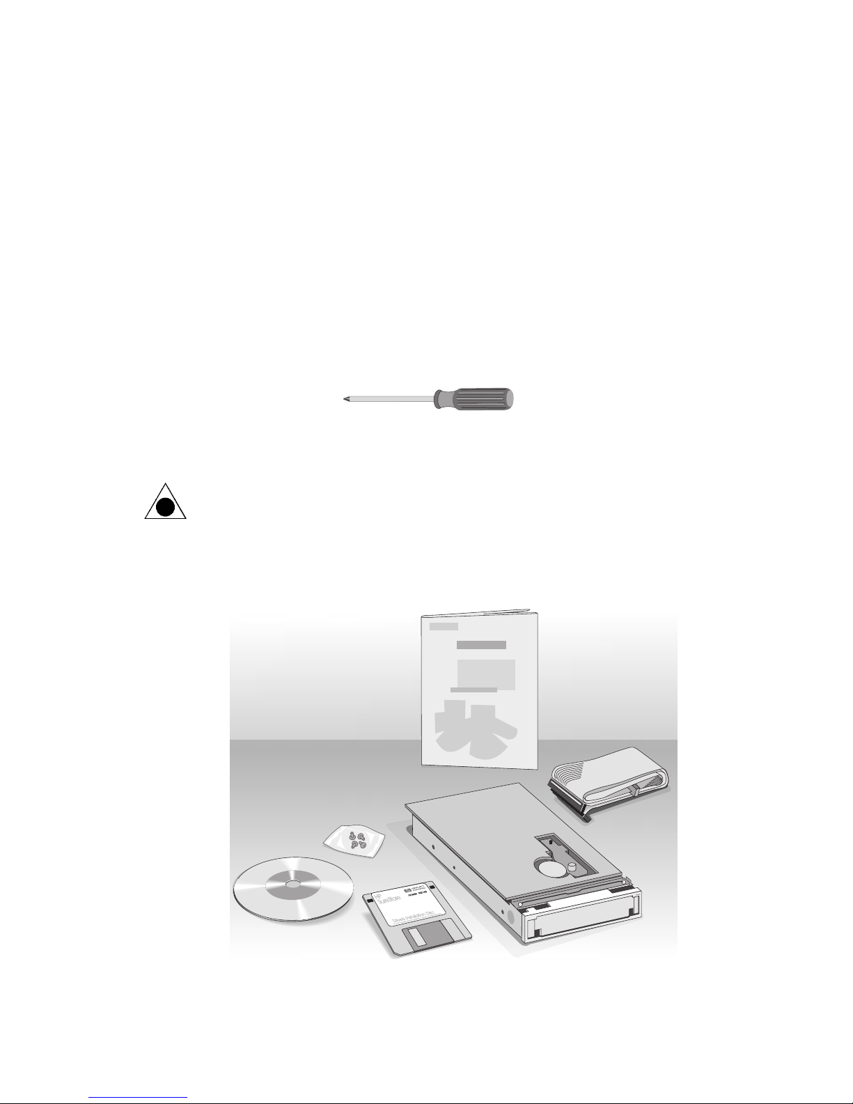
1. Locate the following items before you begin to install the tape drive:
■ A medium-size Phillips screwdriver
■ Your computer system’s manual (you may need to look up
information about the location of your IDE controllers).
CAUTION: The discharge of static electricity can damage electronic circuitry.
You can avoid static discharge by touching a grounded metal object such as
your computer’s case before and during installation of hardware inside your
computer or by wearing a grounding strap.
Software
Installation
CD
2. Make sure you have the items shown below.
Installation Guide
Screws
Install Assistant
Program Diskette
OPTIONAL
Data Cable
(you may not
need this)
HP Colorado
Tape Drive
4
Page 5
Installing the Hardware 5
3. Run the Install Assistant program, if you have not already done so (see
page 3).
4. Remove the Install Assistant diskette.
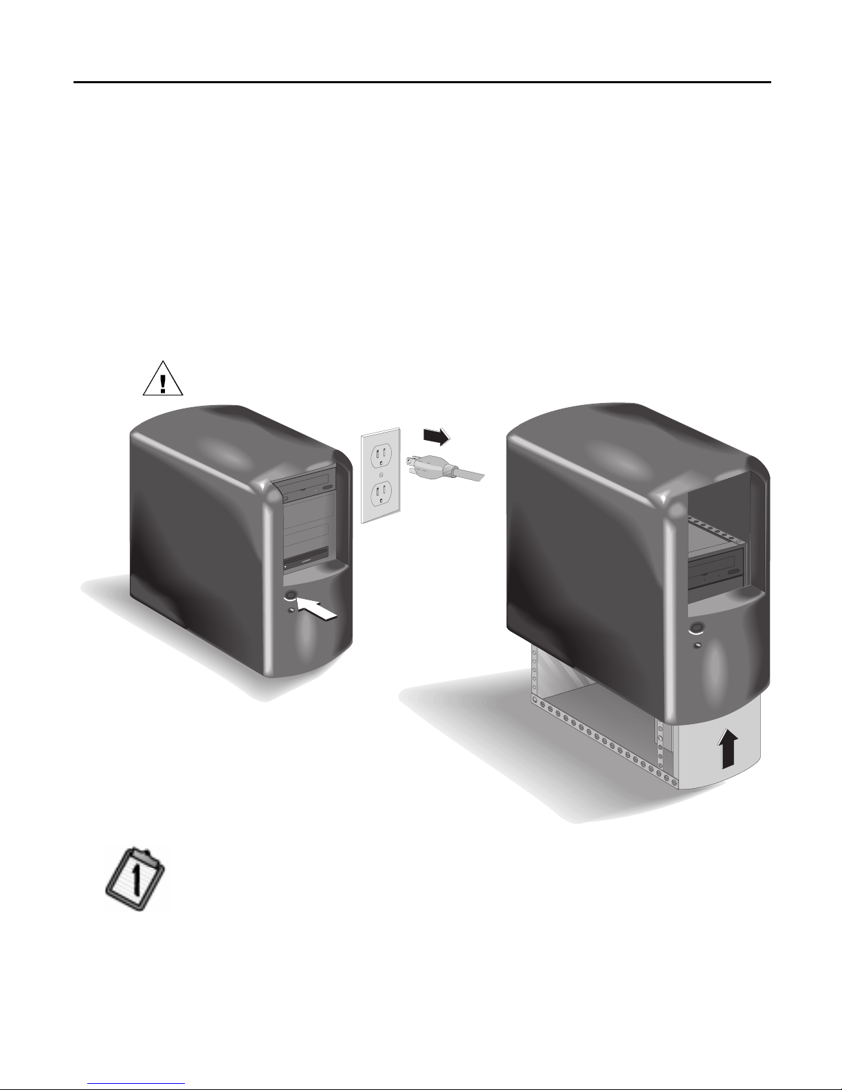
5. Turn OFF your co mpu ter, monitor, and other devices.
Unplug the power cables from the wall outlet or from the power strip, if
you use one. (The power plu g and ou tlet may look different in your
country.)
6. Remove the cover from your computer.
WARNING: Be careful of any sharp edges that may be present inside your
computer.
Computer OFF
See your computer’s
manual if you need help
removing the cover.
7. Refer to the printout from the Install Assistant (see page 3). Find the section
labeled ADDITIONAL IDE CARD REQUIRED?
■ If NO, skip this step.
■ If YES, follow the directions in the HP Colorado IDE Adapter Card
Installation Guide before continuing (contact your local vendor to
purchase the card).
Page 6
6 Installation Guide
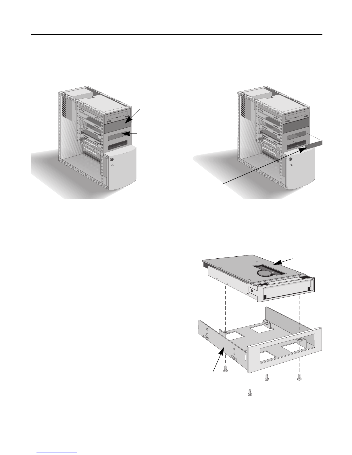
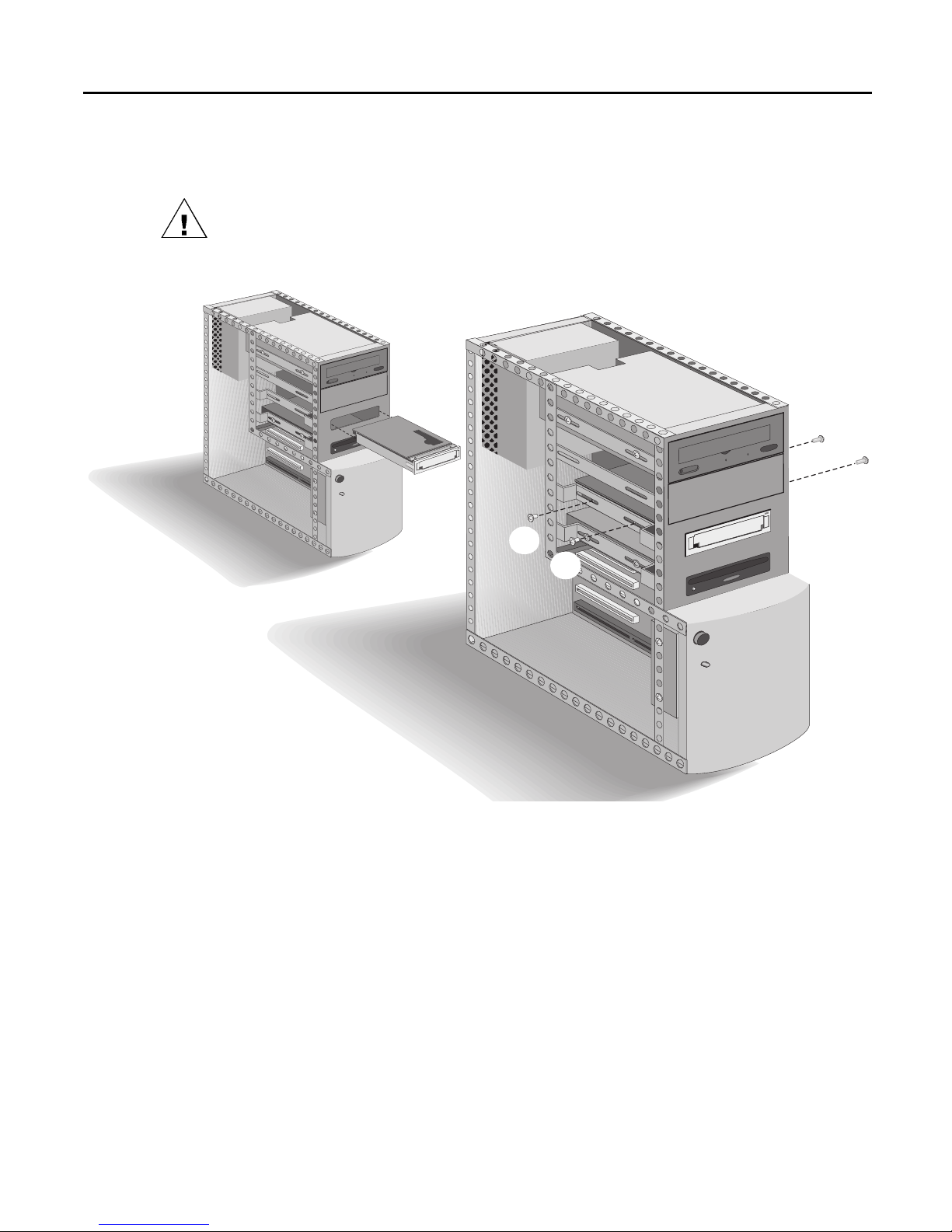
8. Do you want to install the tape drive in a larger “half-height” drive bay or
a smaller “1-inch” drive bay?
Remove the cover plate from the desired drive bay.
Available half-height drive bay
(approx. 6” x 1.75”/15cm x 4.5 cm)
Available 1-inch drive bay
(approx. 3.5” x 1”/8.9 cm x 2.54 cm)
See your computer’s
manual if you need help
removing the dr ive bay cover.
TIP: Keep any mounting hardware such as rails. You will need this
hardware for securing the drive in step 11.
9. If you are installing the tape drive in a larger “half-height” drive bay, skip
this step.
If you are installing the tape
Tape drive
drive in the smaller “1-inch”
drive bay, remove and discard
the mounting bracket from
the tape drive.
The smaller drive bay
configuration (without
mounting brackets ) is
illustrated in the remaining
steps of this guide.
Mounting
Bracket
Page 7
Don’t use
CS (Cable Select)
Installing the Hardware 7
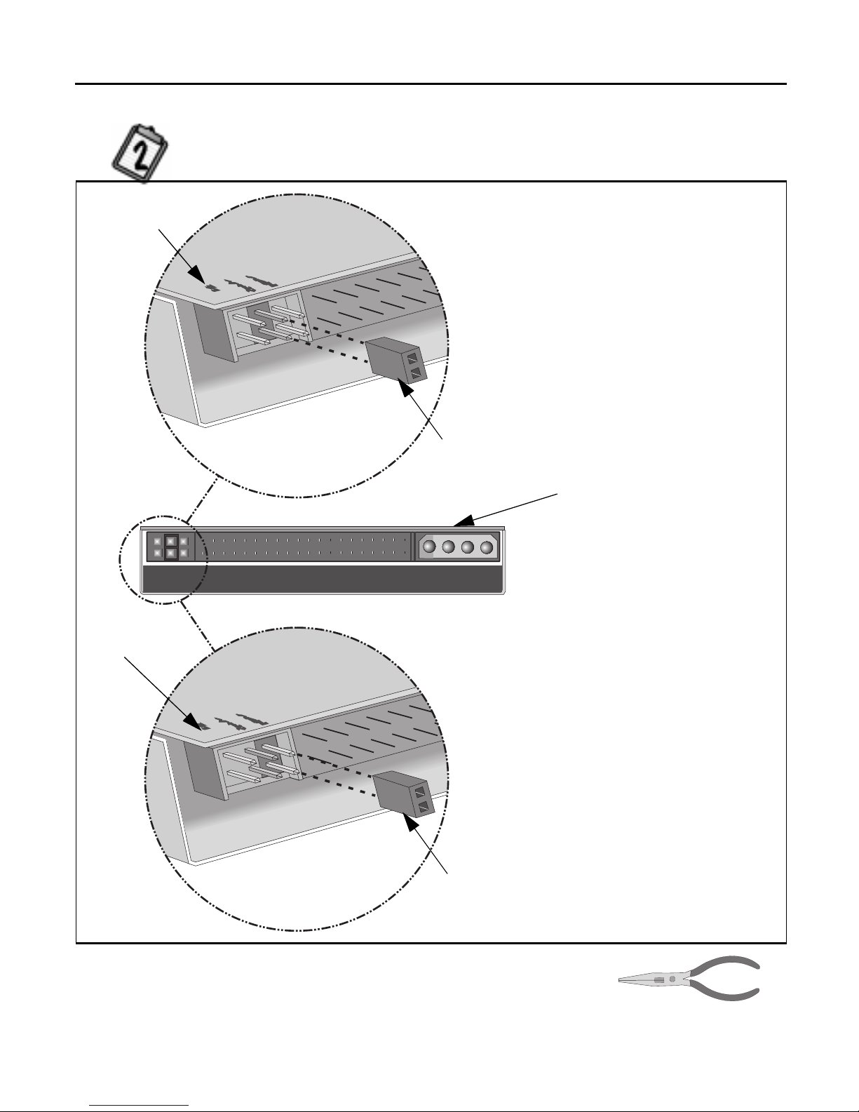
10. Refer to the printout from the Install Assistant (see page 3). Find the section
labeled JUMPER SETTING? Set the jumper as advised.
Slave
Check the back of your tape drive and
make sure the jumper is on the center
location (Slave-SL).
This is a jumper.
Don’t use
CS (Cable Select)
Back view of the tape drive
Green circuit
board is the top
of the drive
or Master
Check the back of your tape drive and
make sure the jumper is on the right-
hand loca tion (Master-MA).
This is a jumper.
TIP: You can use needle-nose pliers
if you need to move the jumper.
Page 8
8 Installation Guide
11. Insert the drive into the drive bay. Be careful not to dislodge any cables
inside your computer as you do this.
WARNING: The drive requires a secure fit. If there is a gap of 1/8 inch (3.2
mm) or more on either side of the drive, you will not be able to secure it. In this
case, obtain an d at t ach “rails” from your comput e r man u f act urer BEFORE
inserting the tape drive. (You may already have what you need from step 8.)
Use all four screws
3
4
1
2
12. If there is not much room around the back of the tape drive, it may be
better to wait until step 17 to complete this step.
Secure the drive into the bay, using the screws included:
■ if installing in the large drive bay , use the silver screws
(#6-32 x 1/4” screws).
■ if installing in the small drive bay, use the black screws
(M3x0.5 x 6 mm metric screws).
The screws electrically ground the tape drive.
Page 9
Installing the Hardware 9
13. Refer to the printout from the Install Assistant (see page 3). Find the section
labeled WHICH IDE CONTROLLER?
TIP: If the Install Assistant stated that your tape drive will share the
data cable with another device (such as your CD-ROM), simply follow
the cable already attached to that device down to the circuit board in
order to locate the IDE controller that you need. If you find an extra
connector along that cable, in the next step, simply attach the tape
drive to that cable. Go to step 14 now.
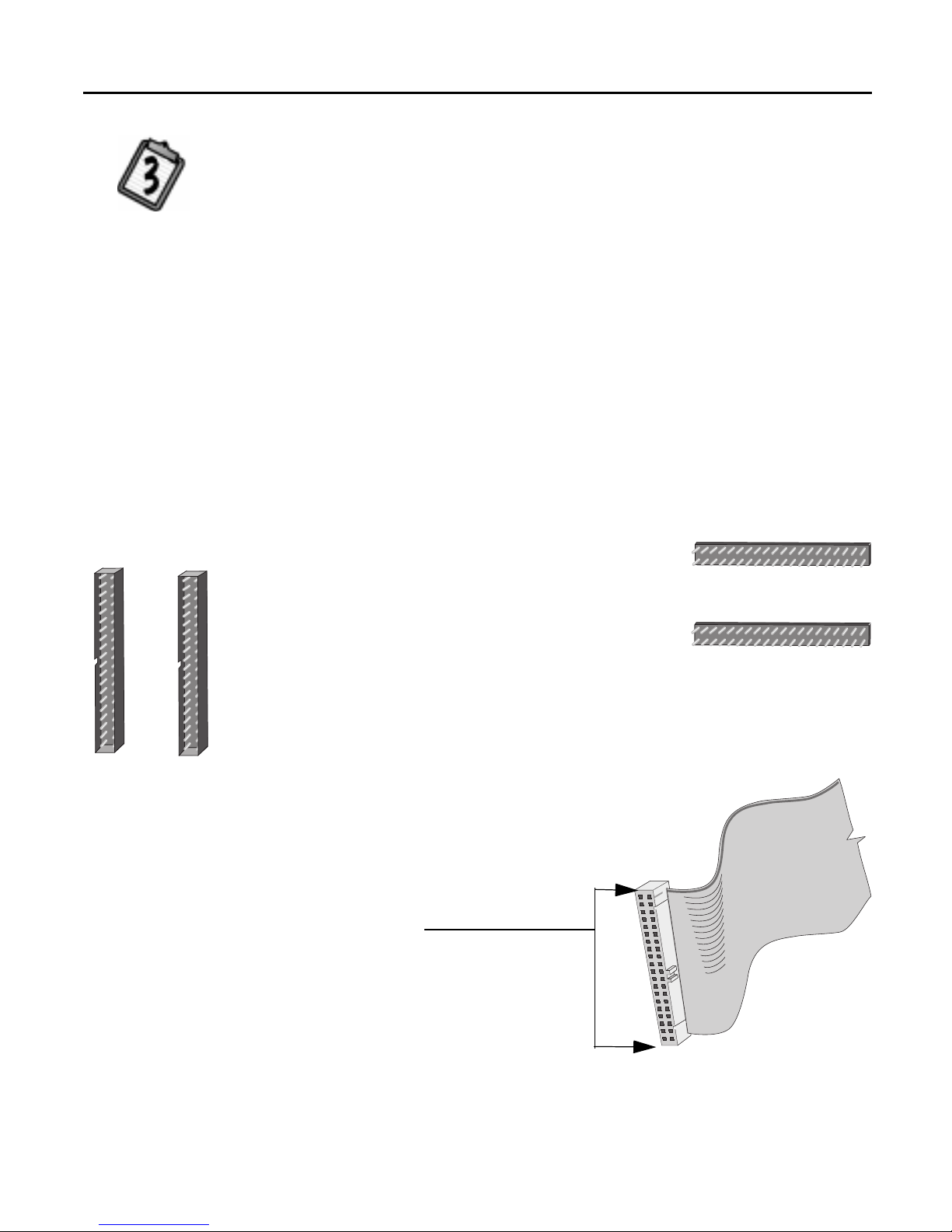
Inside your computer, you may find up to five IDE controllers. Locate the
40-pin IDE controller that will be used by the tape drive as indicated by
the Install Assistant:
■ The first two IDE controllers (Primary and Secondary) are usually on
the mother board of the computer.
■ The third, fourth, or fifth IDE controller may be located on an
expansion card or sound board and may not be labeled.
IDE Controllers
See your computer’s
manual if you need
help finding the
IDE Controller.
Computer manufacturers use a wide variety of
labels for IDE controllers! Look on your
IDE Controllers
Not shown actual size.
computer’s circuit boards for tiny printing such
as:
- PRI and SEC (for primary IDE and secondary IDE)
- IDE-0 and IDE-1
- IDE-1 and IDE-2
- HD and CD-ROM (most common devices to be attached)
- PCI-IDE and ISA-IDE
You will see a variety of connectors inside
your computer that look similar to the 40pin connector but have more or less pins.
Find the connectors that are the correct
size to fit the cable that came in the
box with your drive.
Page 10
10 Installation Guide
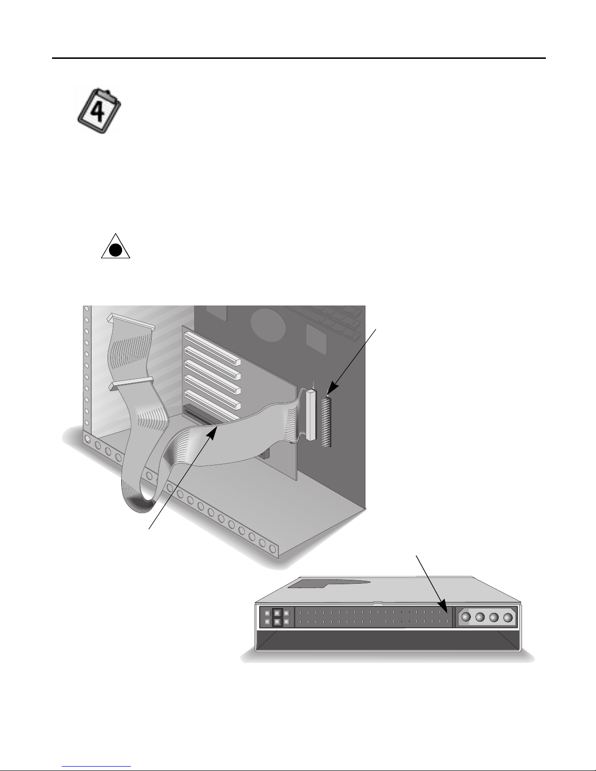
14. Refer to the printout from the Install Assistant (see page 3). Find the section
labeled DATA CABLE INSTRUCTIONS?
Follow the instructions on the next page for either “One Device” or “Two
Devices” as advised.
TIP: If you are sharing the IDE data cable between the HP tape drive and
another device, when the HP tape drive is configured as “Slave” the other
device must be configured as “Master.” Similarly, if the HP tape drive is
configured as “Master” the other device must be configured as “Slave.”
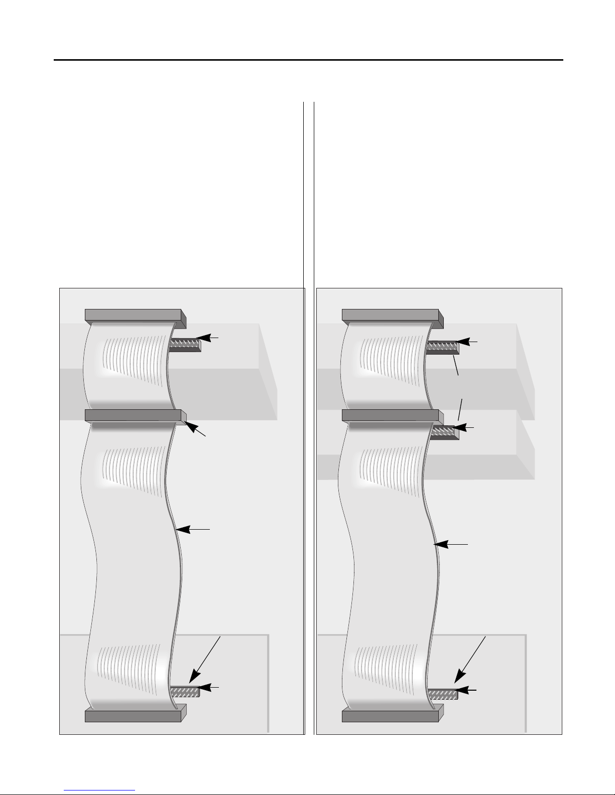
CAUTION: Make sure that you are attaching the cable correctly! You must
locate PIN-1 on each connector and attach the cable so that the edge with the
color stripe is aligned with PIN-1 . If the cable is attached incorrec t ly, your
computer may not boot up.
colored stripe on
the data cable
PIN-1
The cable’s colored edge is aligned
with PIN-1 of the IDE connector.
PIN-1
The cable’s colored edge is aligned
with PIN-1 on the tape drive.
Page 11
Installing the Hardware 11
One Device
The OPTIONAL data cable that came with
the tape drive is only used if there is no cable
already attached to the recommended IDE
controller in your computer system or the
cable supplied with your computer is not
long enough.
Use the connectors at the two ends of the
cable.
PIN-1
HP Colorado tape
drive (end of cable)
Tw o Devices
Attach th e tape drive to whichever connector
is not in use (center or end) on the data cable
already installed in your computer (DO NOT
swap connectors).
The OPTIONAL data cable that came with
the tape drive is only used ins t ead if there is
no spare connector for the tape drive on
your cable or your cable is not long enough.
PIN-1
HP Colorado tape
drive (either location
not in use)
Unused connector
Colored stripe
aligned with
each PIN-1
IDE controller
somewhere inside
your computer
PIN-1
Follow the
data cable
already
attached to the
other IDE device
in your
computer to
locate the IDE
controller
PIN-1
Colored stripe
aligned with
each PIN-1
IDE controller
somewhere inside
your computer
PIN-1
Page 12
12 Installation Guide
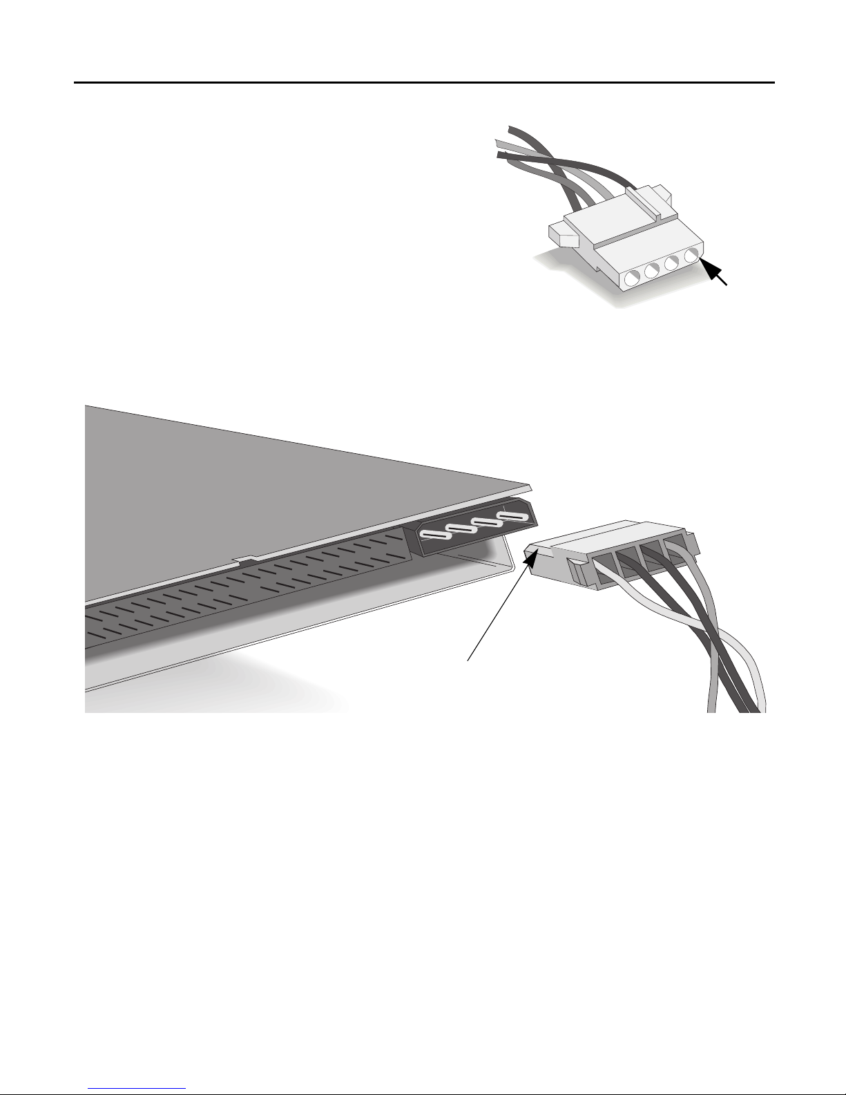
15. Locate your computer’s power
supply. Find an unused power
cable leading from the power
supply.
NOTE: If you do not have an
available power connector, you will
need to purchase a Y -po wer cable that
expands one power connector into
two. Call your local computer
hardware vendor to purchase one.
16. Plug the power cable into the back of the tape drive, with the beveled
edge up.
Beveled
edge
Beveled edge up
17. If you skipped inserting the screws to secure the drive into the bay, do it
now (see step 12).
Page 13
Installing the Hardware 13
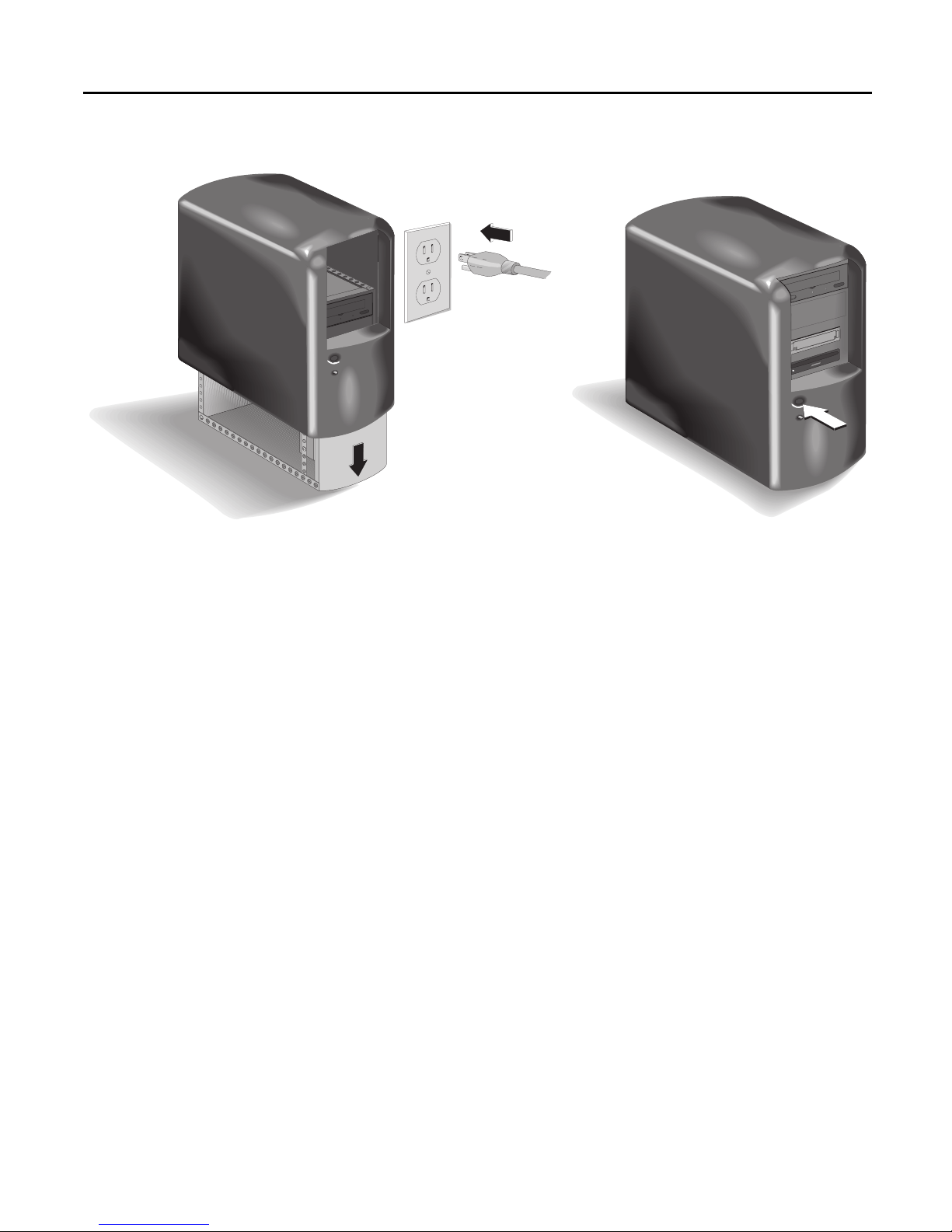
18. Replace your computer's cover.
Computer ON
Plug your computer, monitor, and other devices into a wall outlet or
power strip and turn ON your computer. (The power plug and outlet may
look different in your country.)
TIP: If the drive is sharing the IDE controller with another device,
confirm that the other device is still working properly.
19. Now, insert the diskette labeled Run this first! into your floppy drive and
run the Install Assistant again to verify that the tape drive is installed
correctly.
■ For DOS and Windows 3.1:
Exit to the DOS prompt, type A:\ASSIST (where A: is
your floppy drive letter) and press ENTER.
■ For Windows 95 and NT 4.0:
Click on the Start butt on on t he task bar, click on Run, type
A:\ASSIST (where A: is your floppy drive letter) and click on OK.
20. Run the Install Assistant program and select “Test....” if the program
doesn’t select thi s automati c ally.
21. If success f ul , remove the Install Assistant diskette an d go to pag e 16 for
instructions on installing the Colorad o Backup software.
If you are having problems, continue.
Page 14

14 Installation Guide
If You Have Problems
Did you run the Install Assistant program first (see page 3)?
There are many factors that need to be taken into consideration when
installing an IDE device. By running the Install Assistant program, you
will know how to install successfully without needing to evaluate the
technical details such as IRQs and “single” versus “dual” FIFO.
Does your computer meet the minimum system requirements
See “Minimum System Requirements” on page 42.
Can’t find the IDE controller in your computer?
Check the manual that came with your computer, call the computer
manufacturer for assistance, or check their web site. The IDE controller
may be located on the mother board, a daughter board, sound board, etc.
It may be hard to find because it is behind another component inside
your computer, such as the power supply. Or your computer may not
have a connector attached for access to the IDE controller.
Now your computer won’t boot up!
■ Turn off and unplug your computer. Double-check each connector
along the data cable, look for and straighten any bent pins. The
connectors are inserted properly when all pins are covered up and the
colored stripe on the side of the data cable lines up with PIN-1 of each
connector.
■ Is the power cable attached correctly to each device?
■ If you are sharing the IDE data cable between the tape drive and
another device, did you change the data-cable (middle/end)
connector attached to the devic e that was already inside your
computer?
If yes, change the data-cable connector location back to the original
position. The other device may be jumpered to “cable-select” rather
than “Master” or “Slave.” If this is true, the location of the data-cable
connector (middle/end) is very important.
What is wrong with sharing an IDE data cable with my hard
drive?
The HP Colorado tape drive would run up to 25% slower since it has to
take turns with your hard drive during a backup.
Page 15

Installing the Hardware 15
The device that is sharing the data cable with my HP Colorado
tape drive doesn’t show up in Explorer/File Manager or
doesn’t work any more.
■ Turn off and unplug your computer.
■ Make sure that the power cables are securely attached to both devices.
■ If you are sharing the IDE data cable between the HP tape drive and
another device, did you change the data-cable (middle/end)
connector attached to the devic e that was already inside your
computer?
If yes, change the data-cable connector location back to the original
position. The other device may be jumpered to “cable-select” rather
than “Master” or “Slave.” If this is true, the location of the data-cable
connector (middle/end) is very important.
Achieving optimal performance
Run SCANDISK.EXE and DEFRAG.EXE on your hard drive before using
your tape drive for the first time (see your DOS, Windows 3.x or
Windows 95 manual for more information). Then run them periodically
after that. These programs improve access times to the hard drive, which
will help improve the tape drive’s performance.
Checking for resource conflicts
In rare cases, your computer’s IDE controller may be having a resource
conflict where another device is trying to use the IDE controller’s I/O
base addre ss or interr upt request channel (IR Q ). To che ck for this type of
conflict:
■ In Windows 95, right-click on the My Computer icon, select
Properties, select the Device Manager tab, and double-click on Hard
Disk Controllers, if the list is not already expanded. A yellow
exclamation mark over the contr oller ’s icon confirms that the
controller has the same or conflicting settings as another device
installed on your system. Resolve this conflict by assigning a unique
IRQ and I/O base address the other device.
■ In Windows NT 4.0, if this type of conflict is present, you will see an
error message when you start up Windows NT 4.0. Follow the
directions in the error message box.
Check the read-me file on the software installation CD that
came with your tape drive or the HP web site (see page 54) for
any late-breaking troubleshooting information.
Page 16

Chapter 3: Installing
the Software
Installing the Software for Your Operating System
Your Colorado Backup software installation CD includes the files for
installing the backup software for DOS, Windows, and Windows 95. Your
tape drive can also be configured to work with Windows NT 4.0. Select
the environment you work in and turn to the appropriate section for
installation instructions:
■ DOS — page 17
■ Windows 3.1 or 3.11 — page 23
■ Windows 95 — page 30
■ Windows NT 4.0 — page 34
The Colorado Backup software for DOS, Windows 3.1, and Windows 95,
and the Windows NT applet have the following interchangeability:
You created the backup using:
Colorado
Backup for
You can restore backups using:
Colorado Backup for DOS ver. 5.0 Yes No Yes No
Colorado Backup for Windows
ver. 3.1
Colorado Backup for W indows 95
ver. 3.2
Windows NT 4.0 Backup Applet No No No Yes
CAUTION: If you create backups under more than one operating system, use a
separate set of tapes for each operating system. Label each tape appropriately.
DOS ver.
5.0
No Yes No No
Yes Yes Yes No
Colorado
Backup for
Windows
ver. 3.1
Colorado
Backup for
Windows
95 ver. 3.2
Windows
NT 4.0
Backup
Applet
16
Page 17

Installing the Software 17
NOTE: If your computer has a power-management feature that shuts off your
computer after a specified period of time since the last keyboard input, you may
experience problems with certain operations that exceed the time limit. Turn off
the power-management feature when performing a long running operation such
as a total or full-system backup. Check your computer’s manuals to find out
how to turn off or change the time limit of the power-management feature.
Installing Colorado Backup for DOS
NOTE: Do not install Colorado Backup for DOS for use in Windows 95. This
application does not support Windows 95 conventions such as long filenames
and backups of the registry. See “Installing Colorado Backup for Windows 95”
on page 30.
1. Install the tape drive as described in Chapter 1, “Installing the Hardware”
on page 4. The drive must be installed before continuing.
2. Refer to the printout from the Install Assistant program that you made
AFT ER installing the tape drive. It will tell you how to configure the tape
drive in the following steps.
3. Insert the software installation CD into your CD-ROM drive. If your
computer does not have a CD-ROM, see page 42.
4. At the DOS prompt, type
CD-ROM’s drive letter).
D:\SETUP and press
ENTER
(where D: is your
Page 18

18 Installation Guide
The following screen appears:
5. Select the desired language or leave the default and press
The following screen appears:
Highlight here and press
ENTER to install the
software.
Highlight here and press
ENTER to make an installation
diskette to use on another
computer that does not have a
CD-ROM drive.
Highlight here and press
ENTER for information about
how to view the online user’s
guide.
ENTER
.
Page 19

Highlight here
and press ENTER.
Installing the Software 19
6. Select Install Colorado Backup for DOS.
The following screen appears:
Highlight here and
press ENTER.
7. Select Colorado 8GB, Colorado 5GB, T4000s and press
ENTER
.
The following screen appears:
8. Either accept the default directory name of C:\CBD or type a different
drive letter and directory name where you want Colorado Backup
installed. Select OK.
The following screen appears:
Page 20

20 Installation Guide
9. Highlight IDE and select OK.
The following screen appears:
TAB
Press
the next field.
to move to
When finished, select
OK to accept all the
displayed settings.
10. Refer to the printout from the Install Assistant program (see page 13) and
set each field as instructed, then press
■ Interrupt—The Interrupt Request (IRQ) channel is used by the IDE
■ I/O Base Address—A location in the computer’s address space used
■ Drive Jumper Setting—Two devices can be attached to each IDE
RIGHT-
LEFT-
and
ARROW
highlight the
value to select.
keys to
ENTER
Use the
ARROW
.
controller to indicate to the computer that the drive is ready to send
or receive information.
by the IDE controller to communicate between software and
hardware devices.
controller, one device set to “Master” and one device set to “Slave.”
The following screen appears:
11. If you want to be able to schedule backups to start automatically while
you are away from your computer, press the spacebar to mark the check
box. If you want to save the additional hard drive space required for this
feature or do not wish to do unattended backups, leave the check box
empty. Sele ct OK.
The Colorado Backup files are then copied to your hard drive.
Page 21

Installing the Software 21
When all the files have been copied to your hard drive, the following
screen appears:
12. If the letter of the drive from which your computer boots is not C:, enter
the correct letter. (C: is the most common drive.) Select OK.
13. A screen appears indicating that the software installation was successful.
Select OK. Colorado Backup automatically closes leaving you at the DOS
prompt.
14. Remove the software installation CD from your CD-ROM drive and store
it in a safe place.
15. Reboot by pressing
CTRL+ALT+DEL
.
16. To start the Co lorado Backup softwar e, at the DOS prompt type
CD \CBD (or the name of the installation directory you entered in
step 8.) and press
ENTER
17. Type TAPE an d press
.
ENTER
.
Page 22

22 Installation Guide
The main screen appears:
Menu bar: Select
menu commands from
here.
Command push buttons
To copy files from your
hard drive to a tape,
select this button.
To restore files on tape to
a hard drive, select this
button.
T o compare files on tape to
files on your hard drive (in
order to verify that you will
be able to restore your
backup), select this button.
Status line:
Displays a short
help message.
18. If the Colorado Backup window does not appear or you receive an error
message, see “If You Have Problems” on page 34.
If you are ready to perform tape operations, read:
■ “Using Tapes and Caring for Your Tape Drive” on page 37.
■ The online Colora do Backup Us er’s Guide or click on Help! inside the
software to learn how to back up and restore data, compare files, and
use the application’s options and features.
For more information on accessing the User’s Guide, see “Viewing the
Online User’s Guide” on page 2.
Page 23

Installing the Software 23
Installing Colorado Backup for Windows (3.1 or 3.11)
NOTE: Do not install Colorado Backup for Windows for use in Windows 95.
This application does not support Windows 95 conventions such as long
filenames and backups of the registry. See “Installing Colorado Backup for
Windows 95” on page 30.
1. Attach the tape drive as described in Chapter 1, “Installing the
Hardware” on page 4. The drive must be attached to install and configure
the software.
2. Refer to the printout from the Install Assistant program that you made
AFT ER installing the tape drive. It will tell you how to configure the tape
drive in the following steps.
3. Insert the software installation CD into your CD-ROM drive. If your
computer does not have a CD-ROM, see page 42.
4. In Windows, open the Program Manager window, if it is not already
open.
5. From the Windows’ Program Manager, Click on the File menu and select
Run. The Run box appears.
6. In the Command Line box, type
your CD-ROM’s drive letter).
The following screen appears:
D:\SETUP and press
ENTER
(wher e D: is
7. Select the desired language or leave the default and click Next.
Page 24

24 Installation Guide
The following screen appears:
Click here to install the
software.
Click here to make an installation
diskette to use on another
computer that does not have a
CD-ROM drive.
Click here to view the online
user’s g u ide. The first time you
click here, you will have the
option of installing Acrobat
Reader software, if you do not
already have it.
8. Click on the Install button.
The following screen appears:
9. Either accept the default directory of C:\CBW or type in a new directory
name. Then click on OK.
10. A dialog box appears explaining that the installation process must alter
your AUTOEXEC.BAT, CONF IG.SY S, WI N.INI , and SY STEM.INI files.
Current copies of these files are saved with the extension OLD in the
directory indicated in the previous step. Click on OK to proceed.
Page 25

Installing the Software 25
The Colorado Backup files are then copied to the directory indicated in
step 9.
11. After the files are copied, the Colorado Backup main window appears
with a dialog box indicating that Windows needs to be restarted before
Colorado Backup will work properly . Make sure all applications are closed
and click on OK. Colorado Backup and Windows are exited and restarted.
When the main window reappears, you are ready to configure the tape
drive.
Configuration begins wi th the following dialog box. Click on any Help
button if you need more information about the displayed dialog box.
Select this one.
12. Click on ATAPI tape drive (Colorado 8GB or 5GB), then se l e c t OK.
The following screen appears:
Page 26

26 Installation Guide
13. Refer to the printout from the Install Assistant program (see page 13) and
set each field as instructed, then click on OK.
■ I/O base address—A location in the computer’s address space used by
the IDE controller to communicate between software and hardware
devices.
■ IRQ—The Interrupt Request (IRQ) channel is us ed by the IDE
controller to indicate to the computer that the drive is ready to send
or receive information.
■ Master/Slave —Two devices can be attached to each IDE controller,
one device set to “Maste r” and on e devi c e se t to “ Sla ve.”
14. The Boot Drive dialog box appears prompting you for the drive from
which your computer boots (starts). Make sure the correct drive letter is
entered and click on OK.
15. A dialog box appears indicating that the software installation was
successful and that you m ust exit Windows and reboot your computer to
complete the configuration process. Click on OK.
16. Exit Windows and, from the DOS prompt, reboot your computer by
pressing
CTRL+ALT+DELETE.
17. Start Windows and double-click on the Backup icon in the new
Colorado Backup group.
The following dialog box appears:
Note the instructions for
scheduling an automatic
system backup.
Page 27

Double-click on
this icon to start
Colorado Backup.
Double-click on
this icon to set up
an automated
backup schedule.
Installing the Software 27
18. Click on OK.
Colorado Backup for Windows shuts down and you are left in Windows’
Program Manager with the Colorado Backup for Windows program
group displayed:
Double-click on
this icon to
backup all files
that have
changed since
your last
backup.
Double-click on
this icon to start
a backup of all
files on all local
hard drives.
The software is now installed. You can open the software and make your
first backup, or you can set up the Automated Daily Backup as described
in the following steps.
19. If you want Colorado Backup to make backups automatically, doubleclick on the Automated Daily Backup icon in the Colorado Backup for
Windows program group.
The scheduling dialog box appears.
When turned on, the Automated Daily Backup feature creates the
following operations:
■ Automated Total—This operation runs each Monday. The tape is
erased to make room for a Total backup of all detected local hard
drives. It then copies all files—applications, systems files, and data
files—from each detected local hard drive. The files on tape are then
Page 28

28 Installation Guide
compared to the original hard drive files to ensure their accuracy. This
provides a complete copy of your hard drive(s) at the time of the
backup.
■ Automated Modified —This operation runs each day from T uesday to
Sunday , backing up only files that have been edited or added since
your last backup. Each backup creates a separate volume which is
added to the tape after each previous backup volume. The
combination of Monday’s Total and the six Modified backups give
you an up-to-date copy of all files.
20. To create an automated backup system, select On. The default time of
11:59 p.m. (23:59 if you are using a 24-hour clock) appears as the
scheduled time for the daily backup.
21. Accept the default t ime or enter th e time you prefer to hav e your backu ps
run automatically. Click on OK.
22. An explanation of the Automated Daily Backup appears. Click on OK.
An icon labeled Colorado Scheduler appears on your desktop.
This icon indicates the Automated Daily
Backup is on and the daily operation will
run at the scheduled time.
The presence of the icon indicates that the macros will run at their
specified times if you:
■ Leave a tape in your tape drive
■ Exit out of Colorado Backup for Windows
■ Leave your computer on with Windows running
23. Remove the software installation CD from your CD-ROM drive and store
it in a safe place.
24. To open Colora do Backup, double-click on the Backup icon.
Page 29

Floppy-drive icon:
One for each floppy
drive installed in
your computer.
Hard-drive icon: One
for each hard drive
installed on your
computer. If you are
connected to a
network, mapped
drives and network
servers also appear.
Installing the Software 29
The Colorado Backup main window appears.
Tape-drive icon: Labeled
with “No Tape” when there
is no tape in the drive.
Quick Reference: Click on one of
the eight buttons at the bottom of
the window to see instructions for
that operation.
25. If the Colorado Backup window does not appear or you receive an error
message, see “If Y o u Have Problems” on page 34.
If you are ready to perform tape operations, read:
■ “Using Tapes and Caring for Your Tape Drive” on page 37.
■ The online User’s Guide or the online Help to learn how to back up
and restore data, compare files, and use the application’s options and
features.
For more information on accessing the User’s Guide, see “Viewing the
Online User’s Guide” on page 2.
Page 30

30 Installation Guide
Installing Colorado Backup for Windows 95
NOTE: Do not use Colorado Backup for Windows 95 to backup Novell servers.
Colorado Backup for DOS can backup Novell 2.x and 3.x servers or Colorado
Backup for Windows (3.1 or 3.11) ca n backup Novell 3.x servers.
NOTE: Colorado Backup for Windows 95 can back up computers over your
Windows 95 and Windows for Workgroups networks. However, Colorado
Backup for Windows 95 will only back up the Windows 95 registry of the
computer to which your tape drive is attached. The Windows 95 registry of a
remote computer will not be backed up.
1. You will need two formatted, 3.5” (1.44 MB) diskettes labeled “Recovery
Disk #1” and “Recovery Disk #2” to use in step 13.
2. Attach the tape drive as described in Chapter 1, “Installing the
Hardware” on page 4. The drive must be attached to install and configure
the software.
3. Insert the software installation CD into your CD-ROM drive. If your
computer does not have a CD-ROM, see page 42.
4. If the first screen does not appear automatically , click the Start button on
the Windows 95 task bar, select Run, ty pe
CD-ROM’s drive letter), then cli ck on OK. The following screen appears:
D:\SETUP (where D: is your
Page 31

Installing the Software 31
5. Select the desired language or leav e the default . Click on Next. The
following menu appears:
Click here to install the
software.
Click here to make an installation
diskette to use on another
computer that does not have a
CD-ROM drive.
Click here to view the online
user’s guide. The first time you
click here, you will have the
option of installing Acrobat
Reader software, if you do not
already have it.
Click here to view the CD’s
contents.
6. Click on the Install button. Follow the instructions on the screen.
7. When prompted to restart your computer, click on Yes. Y our com puter is
restarted and Windows 95 reappears with the Colorado Backup icon on
the desktop.
8. Exit the menu window and remove the software installation CD from
your CD-ROM drive and store it in a safe place.
9. To start Colorado Backup, double-click on the Colorado Backup icon
that appears on your desktop, or:
■ Click the Start button.
■ Highlight Programs.
■ Select the Colorado Backup program group.
■ Select the Colorado Backup program.
10. A registration screen appears. Follow the instructions on the screen to
register your Colorado Backup software.
Page 32

32 Installation Guide
11. The Recovery Disk Creation screen appears:
12. Click on the Create Recovery Disks Now button. The following screen
appears:
13. Insert the formatted, 3.5” (1.44 MB) diskette labeled “Recovery Disk #1”
into your floppy drive. You must use your primary, or bootable floppy
drive. Click on Continue.
14. When prompted, remove Recovery Disk #1 from the drive and insert the
diskette labeled “Recovery Disk #2.” Click on OK to continue.
Page 33

Installing the Software 33
15. Click on Continue. When all the necessary files have been copied to the
diskette, the following screen appears:
16. Remove “Recovery Disk #2” from the floppy drive and write protect both
diskettes. Store the two recovery disks together in a safe place.
17. Click on OK. The Colorado Backup main wind ow ap pears.
18. If the Colorado Backup window does not appear or you receive an error
message, see “If You Have Problems” on page 34.
If you are ready to perform tape operations, read:
■ “Using Tapes and Caring for Your Tape Drive” on page 37.
■ Read the User’s Guide or the online Help to learn how to back up and
restore data, compare files, and use the application’s options and
features. To read the online help while you are using Colorado
Backup, select Help from the menu bar.
For more information on accessing the User’s Guide, see “Viewing the
Online User’s Guide” on page 2.
Page 34

34 Installation Guide
Configuring the drive for Windows NT 4.0
Your HP Colorado tape drive can be successfully installed with Windows
NT 4.0. Use the backup application that is part of the standard Windows
NT 4.0 setup. Do not install the Colorado Backup software that came
with your tape drive.
1. Install your tape drive as directed in “Installing the Hardware” on page 4.
2. Start up your comp uter and log in with Administrative rights.
3. Go to the Control Panel and choose the Tape Devices icon.
4. Go to the Drivers tab and click on Add.
5. Windows NT creates a list of tape drivers. Click on the Have Disk button.
6. When prompted to enter the path for the manufacturer’ s files, type
D:\NT (where D: is you CD-ROM’s drive letter). If your computer does
not have a CD-ROM, see page 42.
7. Click OK.
8. A list of t ape devi ces appea rs. Sel ect Hewlett-Packard Colorado IDE. The
necessary files are copied to your system.
9. Restart the system when prompted. If no ser vices fail, the drive is ready
to use. If services fail, please contact our QuickFax service for document
5228. The QuickFax phone numbers are listed on page 54.
10. Start the Backup application by clicking on Start, Programs,
Administrative Tools, and Backup.
11. Use NT Backup online Help to learn how to back up and restore data,
compare files, and use the application’s options and features.
If You Have Problems
If you receive any error messages when starting Colorado Backup, check
the following items:
■ Exit out of all applications. T u rn off the computer’s power, wait 20
seconds, then turn it on again. (This is called cycling power.) Then start
Colorado Backup.
■ Verify that your computer meets the requirements listed in
Page 35

Installing the Software 35
“Minimum System Requirements” on page 42 for the operating
system in which you are using Colorado Backup.
■ Does the drive move the tape when the tape is inserted? If not, check
the power connections to the tape drive.
■ Are all of your peripheral devices plugged in and turned on?
■ Are all the expansion boards inside your computer firmly seated?
■ Are all cables inside your computer connected to the appropriate
device or expansion board?
■ Are peripheral and power connectors plugged into the back of your
computer?
■ Your IDE controller may be using the same IRQ setting as some other
device in your computer system. For example, a sound board or fax/
modem board may be using the same IRQ (see “Checking for resource
conflicts” on page 15).
■ Defragment your hard drive using a defragmenting application or
utility (see “Achiev ing optimal performance” on page 15).
■ Make sure you are using the right type of tape. See “Choosing Tapes
for Your Tape Drive” on page 37.
■ Windows and Windows 95 users: If the tape-drive icon appears with
a red mark through it, the software either cannot find the drive at the
selected settings, or the inserted tape is not compatible. (Windows 3.x
users can click on the tape icon to read the error message.) Exit the
software and restart it. If the mark remains, try the operation with a
different tape.
■ If your computer has a power-management featur e that shuts off your
computer after a spe cified period of time since the last ke yboard
input, you may experience problems with certain operations that
exceed the time limit. Turn off the power-management feature when
performing a long running operation such as a total or full-system
backup. Check your computer’s manuals to find out how to turn off
or change the time limit of the power-management feature.
The computer is trying to boot up from the HP Colorado tape
drive or receiving “Invalid Media” error message
■ If the computer is trying to boot up the operating system from the HP
Colorado tape drive, simply remove the tape from the tape drive
when starting up your computer.
■ To get your computer to stop this behavior, you need to change the
Page 36

36 Installation Guide
“boot order” settings in your CMOS program. T o learn how, see the
documentation th at cam e with your computer or call the computer
manufacturer.
Page 37

Chapter 4: Using Tapes
and Caring for Your
Tape Drive
Choosing Tapes for Your Tape Drive
To ensure the highest level of performance, HP Colorado brand tapes
(which have been fully tested with your drive) are recommended.
Part No Product
C4427A 1 pack TR-3 3.2 GB
minicartridge
C4427B 2 pack TR-3 3.2 GB
minicartridge
C4427D 5 pack TR-3 3.2 GB
minicartridge
C4429A 1 pack HP Colorado
5.0 GB cartridge
C4429B 2 pack HP Colorado
5.0 GB cartridge
C4429D 5 pack HP Colorado
5.0 GB cartridge
C4425A 1 pack TR-4 8.0 GB
minicartridge
C4425B 2 pack TR-4 8.0 GB
minicartridge
HP
Colorado
T3000
RW R R
RW R R
RW R R
HP
Colorado
5GB
RW RW RW
RW RW RW
RW RW RW
HP
Colorado
8GB
RW RW
RW RW
HP
Colorado
4i/e
C4425D 5 pack TR-4 8.0 GB
RW Read/Write, R Read only
RW RW
minicartridge
37
Page 38

38 Installation Guide
In Windows 95 only, your tape drive can also read from but NOT write
to backup tapes made using Colorado Backup software and a Jumbo 250,
350, 700, 1400; Trakker 250, 350, 0r 700; T1000; or T3000 tape drive.
The following section explains how to insert your tapes. Please note the
differences between the HP Colorado cartridges and the standard minidata cartridge when they are fully inserted.
CAUTION: Do not erase C4425 or C4429 tapes with bulk erasers. Magnetic
bulk erasing removes tracking refer ence points that ar e p laced on the tape at the
factory. Without these points, the tapes canno t be read by your tape drive. The
Erase utility in Colorado Backup is the safest and quickest method of removing
data from your tapes.
Page 39

Using Tapes and Caring for Your Tape Drive 39
Inserting Tapes
1. Hold the tape with the metal base plate down and the tape-access
window facing the drive.
Tape-access window
Metal base plate
2. Align the tape with the tape drive’s opening and push the tape firmly
into the drive. Y ou will feel it lock into place.
After the cartridge is inserted, you will hear the sound of the tape being
wound back and forth. This sound indicates that the tape drive is finding
the beginning of the tape, determining the tape’s length and format, and
positioning the drive’s read/write head.
Page 40

40 Installation Guide
Note the differences between the two cartridge types when they are fully
inserted as shown in the following illustrations:
.
HP Colorado cartridge or
Travan cartridge
The wider Travan
cartridge spans the entire
width of the drive’s
opening.
Standard mini cartridges
Approximately 1”
(2.5cm) of the cartridge
extends out of the drive
when fully inserted.
Mini-data cartridges are
narrower, leaving gaps on
each side of the tape
when inserted.
Removing Tapes
1. Wait until the light on the front of your tape drive quits blinking. (DO
NOT remove a tape during an operation. See the CAUTION note below.)
2. Grasp the tape cartridge firmly and pull it straight out from the drive.
CAUTION: Interfering with a tape during operations may cause data loss, and
may make the tape temporarily unrecordable. If, during a backup, you pull the
tape out of the drive, turn off the power to the computer, or firmly bump the
tape, you will not be able to read the data currently written to the tape. Also,
the tape will not be recordable until it is erased with Colorado Backup’s Erase
utility. (Never use a magnetic bulk eraser to erase your HP Colorado tapes. Bulk
erasers remove reference points on the tape that ar e vital. Removing these points
makes tapes un us able.)
Approximately 0.75”
(2cm) of the cartridge
extends out of the drive
when fully inserted.
Page 41

Using Tapes and Caring for Your Tape Drive 41
Caring for Your Tape Drive
You do not need to perform any routine maintenance on the HP
Colorado tape drive.
CAUTION: Do NOT clean the read/write head of an HP Colorado tape drive.
CAUTION: Do NOT degauss or demagnetize the read/write head of an HP
Colorado tape drive. Damage to your tape drive will result.
Page 42

Chapter 5: Technical
Information
Minimum System Requirements
Your computer must meet or exceed these requirements:
■ An IBM-compatible computer (486/16 MHz class or higher for DOS
and Windows 3.1 or 3.11, 486/25 MHz class or higher for Windows
95 or Windows NT 4.0).
■ An available space on a n ID E controller (ATA-2 or EIDE).
■ One available installation bay.
■ A CD-ROM drive to install the backup software.
If your computer does no t have a CD-ROM dr ive:
You can make in stalla tion disk ette s by usi ng anot her co mputer to
which you have access.
Insert the software installation CD, run the SETUP program, and
select Create Installation Disks. From the diskettes, run either
INSTALL (DOS) or SETUP (Window 3.x, Windows 95 or NT).
■ If you need special rails, cables, or other accessories to install the tape
drive, contact your computer manufacturer or local computer
hardware vendor to purchase them.
■ See the operating system requirements on the following pages.
42
Page 43

Technical Information 43
Colorado Backup for DOS Requirements
Installing Colorado Backup for DOS requires:
■ DOS 5.0 or higher. To identify your version, type VER at the DOS
prompt and press
■ A minimum of 512 KB of conventional memory. Performance is
ENTER
likely to improve with more available memory . T o check free memory,
MEM at the DOS prompt and press
type
“Largest executable program size” should be at least 524,288.
■ 6 MB of available hard drive space (1 MB for the software and an
additional 5 MB of space for operations overhead). To check available
hard drive space, type
“Bytes available on hard drive” should be at least 6 MB.
.
CHKDSK
ENTER
. The value listed after
at the DOS prompt and press
ENTER
.
Colorado Backup for Windows Requirements
Installing Colorado Backup for Windows requires:
■ Windows version 3.1 or 3.11 running in 386 Enhanced mode. To
verify your version and mode, from the Program Manager , open the
Help menu, then se l e c t About Program Manager. The software
version is listed and “386 Enhanced Mode” must appear in the box.
■ 4 MB of RAM in Windows 3.1
8 MB of RAM in Windows for Workgroups
■ 10 MB of available hard drive space (5 MB for the software and an
additional 5 MB of space for operations overhead). To check available
hard drive space, double-click on the File Manager icon in the Main
program group. Then click on the icon for the hard drive where
Colorado Backup is to be installed (C: is the default). The amount of
free hard drive space appears at the bottom of the window . It must be
at least 10,000 KB.
In addition, the following is recommended but not required:
■ Your computer might be running either the SHARE.EXE or
VSHARE.386 (but not both). If either is running, you will find
SHARE.EXE in either your CONFIG.SYS or AUTOEXEC.BAT file, a n d
VSHARE.386 will be in your SYSTEM.INI file.
See your Microso f t Windows User’s Guide for more information.
Page 44

44 Installation Guide
Colorado Backup for Windows 95 Requirements
Installing Colorado Backup for Windows 95 requires:
■ Windows 95
■ 8 MB of RAM
■ 20 MB of available hard driv e space (15 MB for the software and an
additional 5 MB of space for operations overhead). T o check available
hard drive space, double-click on My computer; click on the icon
representing the hard drive on which the backup software will be
installed; open the File menu and select Properties. Available hard
drive space must be at least 20 MB.
Windows NT 4.0
You can use the Windows NT Backup applet with this tape drive.
LAN Installation
When using Colorado Backup on a LAN, the tape dr iv e hardw are and
software must be installed in a workstation. Do not install them on the
network server. For other LAN installation options, call the Customer
Support phone number listed on page 54.
NOTE: Do not use Colorado Backup for Windows 95 to backup Novell servers.
Colorado Backup for DOS can backup Novell 2.x and 3.x servers or Colorado
Backup for Windows (3.1 or 3.11) ca n backup Novell 3.x servers.
NOTE: Colorado Backup for Windows 95 can back up computers over your
Windows 95 and Windows for Workgroups networks. However, Colorado
Backup for Windows 95 will only back up the Windows 95 registry of the
computer to which your tape drive is attached. The Windows 95 registry of a
remote computer will not be backed up.
Page 45

Technical Information 45
What Affects Performance
How well your new HP tape drive functions, particularly how fast it
writes data to tape, depends on a number of factors. Some of these factors
are listed below .
Processor (CPU). The type and speed of your processor greatly affects the
speed at which your computer transfers data to and from the tape drive.
RAM. Your computer must have enough memory available to handle its
operating system, the backup software, and the data you are transferring
to and from tape. The system should not have to swap data to and from
the hard drive. Shut down other program s du ring a backup to ensure
optimal speed.
IDE Interface Type: To use the internal tape drive, your computer
requires an available connector on an IDE controller . Your computer may
have a “Single-FIFO” or “Dual-FIFO” IDE controller. If it is “Single-FIFO,”
the tape drive will run 12-25% slower than with a “Dual-FIFO” IDE
controller . Insert the Install Assistant diskette, run ASSIST.EXE /S to see
an evaluation of yo ur com puter system.
Hard Drive. If you attach the HP Colorado tape drive to the same IDE
controller as a hard drive, the tape drive will run slower because it must
take turns using the data cable with the hard drive.
For optimal performance, run SCANDISK.EXE and DEFRAG.EXE. See
“Achieving optimal performance” on page 15.
NOTE: Refer to your computer and mother board manuals or contact your
computer vendor if you have any questions about your computer’ s configuration
or capabilities.
Page 46

46 Installation Guide
Drive Specifications
Backup Speed
Performance will vary greatly depending on the speed of your system, the
current fragmentation of your hard drive, and the number and type of files
being backed up.
Data transfer rate: up to 648 KBps
Tape speed, Read/write: up to 102 inches per second
Search/rewind: 120 inches per second
Load time: 15 seconds
Tape Format
QIC-3095
Number of tracks: 73
Bit density: 67,733
Encoding method: RLL1,7
Error Correction: 6-level Reed-Solomon
Interface
ATAPI
Reliability Specifications
15
Hard error rate: <1 in 10
Mean time between failure: 250,000 hours predicted
Warranty: 2-year limited warranty
Power Require me nts
+5 Vdc @ 0.7 A
+12 Vdc @ 1.0 A
Specified Operating Temp erature
o
Minimum: 5
Maximum: 40o C (104o F)
C (41o F)
bits read with Reed-Solomon ECC
Certifications
UL, cUL, TÜV, CE, meets or exceeds FCC Class B requirements
Page 47

Technical Information 47
Canadian Standards Association Information Statement
INSTRUCTION TO USER:
WARNING: This component is only considered to be approved when installed in CSA
certified equipment evaluated to the stan dards C22.2 No. 220-M1986 or C22.2 No. 950M89. The operator accessibility into the end use enclosure is defined with strict accordance
in the operator's manual for the installation of components into the equipment.
User’s manual statement for VCCI class B product
Translation for VCCI class B product
This equipment is in the Class B category information technology equipment based on the
rules of Voluntary Control Council For Interference by Information Technology Equipment
(VCCI). Although aimed for residential area operation, radio interference may be caused
when used near a radio or TV receiver.
Read the instructions for correct operation.
Korean RRL Statement
Notice
Europe: This drive shall be installed only with an EN60950 (IEC950) approved Power supply .
USA/Canada: This drive is for use only with IBM compatible UL
®
listed personal computers.
Page 48

48 Installation Guide
Federal Communications Commission R.F. Interference Statement
WARNING: This equipment has been test ed and found t o comply wi th t he li mits fo r a Clas s
B digital device, pursuant to Part 15 of FCC Rules. These limits are designed to provide
reasonable protection against harmful interference in a residential installation. This
equipment generates, uses and can radiate radio frequency energy and, if not installed and
used in accordance with the instructions, may cause harmful interference to radio
communications. However, there is no guarantee that interference will not occur in a
particular installation. If this equipment does cause harmful interference to radio or
television reception, which can be determined by turning the equipment off and on, the
user is encouraged to try to correct the interference by one or more of the following
measures:
■ Reorient or relocate the receiving antenna.
■ Increase the separation between the equipment and receiver.
■ Connect the equipment into an outlet on a circuit different from that to which the
receiver is connected.
■ Consult the dealer or an experienced radio/TV technician for help.
Information for user:
CAUTION: Changes or modifications of this equipment not expressly approved by Hewlett-
Packard, could result in violation of Part 15 of FCC rules.
DECLARATION OF CON FORMIT Y
according to ISO/IEC Guide 22 and EN 45014
Manufacturer’s Name:
Manufacturer’s Address:
declares that product
Product Name:
Product Number:
Product Options:
conforms to the following Product Specifications:
Safety:
EMC:
Supplementary Information
Hewlett-Packard Company
815 SW 14th Street, Building E
Loveland, Colorado 80537
HP Colorado 5GB internal
C4354A
All
EN60950:1992 +A1:1993, +A2:1993, +A3:1995
EN 55022:1994 Class B
EN 50082-1:1992
IEC 801-2:1991 - 4kV CD, 8kV AD
IEC 801-3:1984 - 3V/m
IEC 801-4:1988 - 1kV Power Lines, 0.5kV Signal Lines
ENV 50140:1993 - 3V/m
The product herewith complies with the requiremen ts of the EMC Direct ive 89/336/ EEC and carries
the “CE” mark accordingly.
August 01, 1997 Richard Spangler
European contact: Your local Hewlett-Packard Sales and Service Office or Hewlett-Packa rd GmbH,
Department HQ-TRE, Herren berger Straβe 130, D-71034 Böblingen (FAX: +49-7031-143143).
Quality Manager
Page 49

.
Manufacturer’s Name:
Technical Information 49
DECLARATION OF CONFORMITY
according to ISO/I EC Gu ide 22 and EN 45014
Hewlett-Packard Company
Manufacturer’s Address:
declares that the product
Product Name:
Model Number:
Product Options:
conforms to the following Product Specifications:
Safety:
EMC:
Supplement ar y In f or m at io n :
The product he rewith complies with the requirem ents of the Low Voltage Direc tive
73/23/EEC and the EMC directive 89/3 36/ EEC and carries the “CE” mark accordingly.
August 01, 1997 Richard Spangler, Quality Manager
European contact: Your local Hewlett-Packard Sales and Service Office or Hewlett-Packa rd GmbH,
Departmen t HP-TRE, Herr enberger Straβe 130, D-71034 Böblingen (FAX: +49-7031-143143).
815 SW 14th Street, Building E
Loveland, Colorado 80537
HP Colorado 8GB internal
C4386A
All
EN60950:1992 + A1:1993, + A2:1993, + A3:1995
EN 55022:1994 Class B
EN 50082-1 : 19 92
IEC 801-2:1991 - 4k V CD, 8kV AD
IEC 801-3:1984 - 3V /m
IEC 801-4:1988 - 1kV Power Lines, 0.5kV Signal Lines
ENV 50140:1993 - 3V/m
Page 50

50 Installation Guide
Software License Agreement for Internal Drives
ATTENTION: USE OF THE SOFTWARE IS SUBJECT TO THE HP SOFTWARE LICENSE TERMS
SET FORTH BELOW. USING THE SOFTWARE INDICATES YOUR ACCEPTANCE OF THESE
LICENSE TERMS. IF YOU DO NOT ACCEPT THESE LICENSE TERMS, YOU MAY RETURN
THE SOFTWARE FOR A FULL REFUND. IF THE SOFTWARE IS BUNDLED WITH ANOTHER
PRODUCT, YOU MAY RETURN THE ENTIRE UNUSED PRODUCT FOR A FULL REFUND.
HP SOFTWARE LICENSE TERMS
License Grant. HP grants you a license to Use one copy of the Software. “Use” means
storing, loading, installing, executing or displaying the Software. You may not modify the
Software or disable any licensing or control features of the Software.
Ownership. The Software is owned and copyrighted by HP or its third party suppliers. Your
license confers no title or ownership in the Software and is not a sale of any rights in the
Software. HP's third party suppliers may protect their rights in the event of any violation of
these License Terms.
Copies and Adaptations. You may only make copies or adaptations of the Software for
archival purposes or when copying or adaptation is an essential step in the authorized Use
of the Software. You must reproduce all copyright notices in the original Software on all
copies or adaptations. You may not copy the Software onto any bulletin board or similar
system.
No Disassembly or Decryption. Y ou may not disassemble or decompile the Software unless
HP's prior written consent is obtained. In some jurisdictions, HP's consent may not be
required for limited disassembly or decompilation. Upon request, you will provide HP with
reasonably detailed information regarding any disassembly or decompilatio n. You may not
decrypt the Software unless decryption is a necessary part of the operation of the Software.
Transfer. Your license will automatically termi nate u pon any tr ans fer o f the S oftwa re. Upo n
transfer, you must deliver the Software, i nc luding any copi es and r elated do cumentat io n, to
the transferee. The transferee must accept these License Terms as a condition to th e tr ansfer.
Termination. HP may terminate your license upon notice for failure to comply with any of
these License Terms. Upon termination, you must immediately destroy the So ftware,
together with all copies, adaptations and merged portions in any form.
Export Requirem ents. You may not export or re-export the Software or any copy or
adaptation in violation of any applicable laws or regulations.
U.S. Government Restricted Rights. The Software and any accompanying documentation
have been developed entirely at private expense. They are delivered and licensed as
“commercial computer software” as defined in DFARS 252.227-7013 (Oct 1988), DFARS
252.211-7015 (May 1991) or DFARS 252.227-7014 (Jun 1995), as a “commercial item” as
defined in FAR 2.101(a), or as “Restricted computer software” as defined in FAR 52.227-19
(Jun 1987) (or any equi valent ag ency regul ation or c ontract clause), whichever is applic able.
You have only those rights provided for such Software and any accompanying
documentation by the applicable FAR or DFARS clause or the HP standard software
agreement for the product involved.
Page 51

Technical Information 51
Hewlett-Packard Limited Warranty Statement
HP Colorado Tape Drive
DURATION OF LIMITED WARRANTY
Hardware - 2 year
Software - 90 days
1. HP warrants to you, the end-user customer, that HP hardware, accessories and supplies
will be free from defects in materials and workmanship after the date of purchase, for the
period specified above. If HP receives notice of such defects during the warranty period, HP
will, at its option, either repai r or replace pr oducts which pro ve to be defective. Replac ement
products may be either new or like-new.
2. HP warrants to you that HP s oft ware wi ll not fa il to ex ecute its pro gra mming instr uc tions
after the date of purchase, for the period specified above, due to defects in material and
workmanship when proper ly i nstal led an d us ed. I f HP receives notice of such defects dur ing
the warranty period, HP will replace software media which does not execute its
programming instructions due to such defects.
3. HP does not warrant that the operat ion of HP product s will be uni nterrupted or error f ree.
If HP is unable, within a reasonable time, to repair or replace any product to a condition as
warranted, you will be entitled to a refund of the purchase price upon prompt return of the
product.
4. HP products may cont ain remanu factured p arts equ ivalent to new in performan ce or may
have been subject to incidental use.
5. Warranty does not apply to defects resulting from (a) improper or inadequate
maintenance or calibration, (b) software, interfacing, parts or supplies not supplied by HP,
(c) unauthorized modification or misuse, (d) operation outside of the published
environmental specifications for the product, or (e) improper site preparation or
maintenance.
6. HP MAKES NO OTHER EXPRESS WARRANTY WHETHER WRITTEN OR ORAL. ANY
IMPLIED WARRANTY OF MERCHANTABILITY OR FITNESS FOR A P ARTICULAR PURPOSE IS
LIMITED TO THE DURATION OF THE EXPRESS WARRANTY SET FORTH ABOVE. So me
states or provinces do not allow limitations on the duration of an implied warranty, so the
above limitation or exclusi on mig ht no t appl y to yo u. Thi s warran ty gives yo u spec ifi c l egal
rights and you might also have other rights that vary from state to state, or province to
province.
7. THE REMEDIES IN THIS WARRANTY STATEMENT ARE YOUR SOLE AND EXCLUSIVE
REMEDIES. EXCEPT AS INDICATED ABOVE, IN NO EVENT WILL HP BE LIABLE FOR LOSS
OF DATA OR FOR DIRECT, SPECIAL, INCIDENTAL, CONSEQUENTIAL (INCLUDING LOST
PROFIT), OR OTHER DAMAGE, WHETHER BASED IN CONTRACT, TORT, OR OTHERWISE.
Some states or provinces do not allow the exclusion or limitation of incidental or
consequential damages, so the above limitation or exclusion may not apply to you.
Consumer transactions in New Zealand, Australia, and the United Kingdom. The
disclaimers and limitations shall not affect the statutory rights of a consumer.
Page 52

52 Installation Guide
Returning Your Drive
All countries other than the USA: If your Hewlett-Packard product requires repair or
replacement, call Customer Support at t he phone number l isted on page 55 of t his g uide to
receive instructions.
In the USA: If your Hewlett-Packard product requires repair or replacement, follow these
instructions:
Call the number listed on page 55. Customer Support will help you determine if your drive
is defective. Provid e the pr oduct t ype, seri al number, and date of purchase . You will be given
a return authorization number. Keep the return authorization (RA) number for future
reference.
Securely repackage the product (in the original packaging if possible) to prevent shipping
damage and mark the return authorization number on the box and in the box along with
your name and address.
All product returns must have an accompanying return authorization number. To ensure
timely and accurate processing of your return, the number must be clearly printed on the
outside of the box.
Use the appropriate address for your location. A traceable shipping method is
recommended. The postage, shipping and insurance charges incurred in shipping to
Hewlett-Packard will be paid by Purchaser and all risk for the product shall remain with
Purchaser until such time as Hewlett-Packard takes receipt of the product.
Once your product is received at Hewlett-Packard, we will ship the replacement product.
Hewlett-Packard will pay s hipping charges to t he Purchas er for repla cement product covered
under warranty.
If the product is st ill un der war ranty, there is no charge for the replac ement. I f the p roduct i s
not covered under warr anty, an exchange cost will be qu oted when t he return autho rizat ion
number is issued.
Page 53

Technical Information 53
Page 54

Chapter 6: Customer
Support Services
Support for Your Tape Drive and Colorado Backup
Software
If you need help with your t ape drive, yo ur loca l reseller has the latest informat ion
regarding HP products and services and can provide support under HP's
comprehensive menu of r eseller s ervices. If yo ur reseller is not able to help, or you
are having software problems, you can obtain support from HP directly either
through free 24-hours/day interactive electronic services or by telephone (free
during warranty).
America O n li ne . . . . . . . . . . . . . . . . . . . . . . . . . . . . . . . . Keyword: hpstor
CompuServe . . . . . . . . . . . . . . . . . . . . . . . . . . . . . . . . . . . . . . . . Go HPSYS
World Wide Web . . . . . . . . . . .http://www.hp.com/go/colorado_support
Bulletin board site ( 8,N,1,F, 1200-28.8K baud)
Europe . . . . . . . . . . . . . . . . . . . . . . . . . . . . . . . . . . . . . +31 (0)495 546909
Asia/Pacific
Australia . . . . . . . . . . . . . . . . . . . . . . . . . . . . . . . . . . . ( 03) 9890 0276
Korea. . . . . . . . . . . . . . . . . . . . . . . . . . . . . . . . . . Hitel: (02) 762-0228
Access: Go HPK
Chollian: (02) 220-2001
New Zealand. . . . . . . . . . . . . . . . . . . . . . . . . . . . . . . . . (09) 356 6642
Taiwan . . . . . . . . . . . . . . . . . . . . . . . . . . . . . . . . . . . . . . (02)9233233
First Name: HP
Last Name: BBS
QuickFax Faxback Service
Simply dial the fax number from a touch-tone phone o r Group 3 fax machi ne and
follow the voice prompts to select the index of available support and product
information documents.
USA and Canada . . . . . . . . . . . . . . . . . . . 800-368-9673 or 97 0-635-1510
Europe
Austria (free line) . . . . . . . . . . . . . . . . . . . . . . . . . . . . . . . .0660 8128
Belgium (free line)
- Dutch . . . . . . . . . . . . . . . . . . . . . . . . . . . . . . . . . . . . . . .0800 1190 6
- French . . . . . . . . . . . . . . . . . . . . . . . . . . . . . . . . . . . . . .0800 17043
Denmark (free line) . . . . . . . . . . . . . . . . . . . . . . . . . . . . . .800 10453
Finland (free line). . . . . . . . . . . . . . . . . . . . . . . . . . . . . . . 9800 13134
France (free line) . . . . . . . . . . . . . . . . . . . . . . . . . . . . . . . .05 905900
54
Page 55

Customer Support Services 55
Germany (free line) . . . . . . . . . . . . . . . . . . . . . . . . . . . 0130 810 061
Italy (free line) . . . . . . . . . . . . . . . . . . . . . . . . . . . . . . . . .1678 59020
Netherlands (free line) . . . . . . . . . . . . . . . . . . . . . . . . . . 06 022 2420
Norway (free line) . . . . . . . . . . . . . . . . . . . . . . . . . . . . . . .800 11319
Spain (free line) . . . . . . . . . . . . . . . . . . . . . . . . . . . . . . . .900 993123
Sweden (free line). . . . . . . . . . . . . . . . . . . . . . . . . . . . . . .020 795743
Switzerland (free line)
- French . . . . . . . . . . . . . . . . . . . . . . . . . . . . . . . . . . . . . . . .155 1526
- German . . . . . . . . . . . . . . . . . . . . . . . . . . . . . . . . . . . . . . .155 1527
United Kingdom (free line) . . . . . . . . . . . . . . . . . . . . . . 0800 960271
Other locations in Europe (toll line) . . . . . . . . . .+31 (0)20 681 5792
Asia/Pacific
Australia . . . . . . . . . . . . . . . . . . . . . . . . . . . . . . . . . . . ( 03) 9272 2627
China . . . . . . . . . . . . . . . . . . . . . . . . . . . . . . . . . . . (8610) -65055280
Japan. . . . . . . . . . . . . . . . . . . . . . . . . . . . . . . . . . . . . . . (3) 3335-8622
Korea. . . . . . . . . . . . . . . . . . . . . . . . . . . . . . . . . . . . . . . (02) 769-0543
New Zealand. . . . . . . . . . . . . . . . . . . . . . . . . . . . . . . . . (09) 356 6642
Singapore . . . . . . . . . . . . . . . . . . . . . . . . . . . . . . . . . . . (65) 291-7951
Taiwan . . . . . . . . . . . . . . . . . . . . . . . . . . . . . . . . . . . . . . (02)7195589
E-mail . . . . . . . . . . . . . . . . . . . . . . . . . . . . . . . . Colorado_Support@hp.com
FTP Site . . . . . . . . . . . . . . . . . . . . . . . . . . . . . . . . . . . . . . . . . . . . ftp.hp.com
Login: . . . . . . . . . . . . . . . . . . . . . . . . . . . . . . . . . . . . . . .anonymous
Password: . . . . . . . . . . . . . . . . . . . . . . . . . . . . . (Your email address)
Directory: . . . . . . . . . . . . . ./pub/information_storage/hp-colorado
Telephone USA and Canada (M-F, 6 am-6 pm Mountain time)
Literature and dealer referral . . . . . . . . . . . . . . . . . . . . 970-635-1500
Canada (for French-speaking customers)
pour assistance en français. . . . . . . . . . . . . . . . . . . . .1-800-387-3867
During warranty period
- Technical support . . . . . . . . . . . . . . . . . . . . . . . . . . . 970-635-1500
After warranty period (charges begin only when you connect to a Support
Technician, prices are subject to change without notice)
Technical Support. . . . . . . . . . . . . . . . . . . . . . . . . . . . . 800-810-0130
(Per incident fee of $25 US dollars charged to
Visa, MasterCard or American Express)
U.S. only Technical Support. . . . . . . . . . . . . . . . . . . . . 900-555-1800
($2.50 per minute/maximum of $25. You must be 18 years
of age or have parental permission to call 900 numbers.)
Europe (M-F, 8:30-18:00 Central European Time)
Use these Technical Support numbers during and after your warranty period. No charge
for Technical Support during warranty period. Per incident charge after warranty period.
Austria (German) . . . . . . . . . . . . . . . . . . . . . . . . . . . . . . .06 60 63 86
Belgium
- Dutch . . . . . . . . . . . . . . . . . . . . . . . . . . . . . . . . . . . . . .02 626 88 06
- French . . . . . . . . . . . . . . . . . . . . . . . . . . . . . . . . . . . . .02 626 88 07
Denmark. . . . . . . . . . . . . . . . . . . . . . . . . . . . . . . . . . . . . .39 29 40 99
Finland . . . . . . . . . . . . . . . . . . . . . . . . . . . . . . . . . . . . . . 02 03 47 288
France. . . . . . . . . . . . . . . . . . . . . . . . . . . . . . . . . . . . . 04 50 43 98 53
Germany. . . . . . . . . . . . . . . . . . . . . . . . . . . . . . . . . . .0180 52 58 143
Page 56

56 Customer Support Services
Ireland (English). . . . . . . . . . . . . . . . . . . . . . . . . . . . . . .01 662 55 25
Italy . . . . . . . . . . . . . . . . . . . . . . . . . . . . . . . . . . . . . . .02 2 641 0350
Netherlands . . . . . . . . . . . . . . . . . . . . . . . . . . . . . . . . . 020 606 8751
Norway. . . . . . . . . . . . . . . . . . . . . . . . . . . . . . . . . . . . . . .22 11 62 99
Portugal . . . . . . . . . . . . . . . . . . . . . . . . . . . . . . . . . . . . .01 44 17 199
Spain. . . . . . . . . . . . . . . . . . . . . . . . . . . . . . . . . . . . . . . .90 23 21 123
Sweden . . . . . . . . . . . . . . . . . . . . . . . . . . . . . . . . . . . . . .08 61 92 170
Switzerland (French, Italian, and German) . . . . . . . . 08 48 80 11 11
United Kingdom. . . . . . . . . . . . . . . . . . . . . . . . . . . . .0171 512 52 02
English language support from other countries . +44 171 512 52 02
Asia/Pacific
Australia (M-F 7am-7pm, Eastern Standard Time). . . (03) 9272 8000
China (M-F 8:30-17:30) . . . . . . . . . . . . . . . . . . . . . (8610)-62625666
extensions 5602 through 5609, 5611 and 5612
Korea (M-F, 8:30-19:00) . . (02) 3270-0700 / 080-999-0700 (toll free)
New Zealand (M-F, 9am to 9pm Auckland Time) . . . . (09) 35 6 6640
Singapore (M-F, 9:00-17:00) . . . . . . . . . . . . . . . . . . . . . (65) 271-7233
Taiwan (M-F, 8:30-17:30) . . . . . . . . . . . . . . . . . . . . . . . (02) 717-9609
(8610)-62614174
(8610)-62624175
(8610)-62614176
FAX
USA. . . . . . . . . . . . . . . . . . . . . . . . . . . . . . . . . . . . . . . . . . . . 970-667-0997
Asia/Pacific
Australia . . . . . . . . . . . . . . . . . . . . . . . . . . . . . . . . . . . ( 03) 9272 4099
Korea. . . . . . . . . . . . . . . . . . . . . . . . . . . . . . . . . . . . . . (02) 3270-0707
New Zealand. . . . . . . . . . . . . . . . . . . . . . . . . . . . . .(+61 3) 9272 4099
Singapore . . . . . . . . . . . . . . . . . . . . . . . . . . . . . . . . . . . (65) 278-9225
Taiwan . . . . . . . . . . . . . . . . . . . . . . . . . . . . . . . . . . . . . . (02)5140276
R
USA: Hewlett-Packard, 815 SW 14th Street Bldg. E, Loveland, CO 80537
Copyright 1998. Hewlett-Packard, a division of Hewlett-Packard. All rights reserved. Hewlett-Packard is a registered
trademark of the Hewle tt -P ackard Company. Windo ws, Windows 95, and Windows NT are U.S. registered trademarks of
Microsoft Corp. Travan is a U.S. registered trademark of 3M.
C4386-90100 March 1998
PRINTED IN USA
 Loading...