

Page 1
HEWLETT-
PACKARD
---
---
------
-------
"_._
HP
r------
I
L.-
3455A
_
Voltmeter
_~~
Operating Manual
- -
----
----------
---,-
--i-
. t _1/
_ _.. _ _ _ ___.__._.._...._.l
---
-----------1
-
f;
-----
-l
~
,
/
Page 2
Ifll
MANUAL
CHANGES
CHANGE
NO.1.
ApplieatoSeriel
Title
Page.
Add the
following
(§!~3
Your
instrument
hardware.
damage to the
tions in the
Contact
ware.
tion
is needed.
SectionI.Paragraph
1-14.
The
3455A.
Option
Option
Option
Option
Option
following
001:
Average Responding AC
907:
908:
909:
910:
Front
Rack
Front
Additional
(For Serial Prefix
For Serial Prefix
(For Serial Prefix
For Serial Prefix
(For Serial Prefix
For Serial Prefix
Operating and Service Manuals
may
00
NOT
intermix
instrument
manual
your
1·14.
Change the paragraph to
options
Handle Kit
·1622
2519
Mounting
1622
2519
Handle Kit and Rack
1622
2519
Manual Part Number
Prefix
2519
and
Above
caution to the
have
either
the
may result.
that
pertain to the
localHPOfficeifmore
are available for
and
below.
and above. use HP PIN
Kit
and below. use HP PIN
and above. use HP PIN
and
below.
and above. use HP PIN
SetofOperating
title
metric
different
Follow
different
the
Converter
use HP PIN
Mounting
use HP PIN
Information
-hp- MODEL
DIGITAL VOLTMETER
page.
or English
hardware
or
the cau-
hard-
informa-
the
following:
use of the Model
5061-0088
5061-9688)
5061-0074
5061-9674)
Kit
5061-0075
5061-9675)
and
3455A
03455~90013
Your
instrument
hardware.
damage to the
result. For
and
above, use
ware, as
prefix
1622
ting
hardware
HP
Officeifmore
CHANGE
NO.2.
Appliea
Add the attached
CHANGE
NO.J.Applies
Section
III.
Paragraph
00
NOT
applyacinputs
than
two
result.
CHANGE
NO.4.
AppliestoSerial
To increase turn-on reliability. a circuitmOdifiea.tion has been made
which
will
I
- 6
October1986
cause the
may
have
either
metric
00
NOT
intermix
instrument's
instruments
metric
listed
above. For
and
below, use English handle/rack moun-
also as
information
to All Serial
"DECLARATION"
to All
J·15.
Add the following caution to the paragraph.
minutes,
3455A
the
different
frame
with
with
handle/rack
instruments
listed
above.
is needed.
Numbers
to the manual.
Serial
Numbers
greater than
or damage to the ac
Number
2591416021
to take 4-7 seconds to turn-on.
and
serial
mounting
Contact
500Vfor
or English
hardware
cabinet
prefix
with
circuitry
and
your
Above.
may
2519
hardserial
local
more
can
or
Supplement A for
03455-90013
111111111111111111111111111111111111111111111111111111111111
3455·90013
Page 3
~lI
MANUAL
CHANGES
CHANGE
NO.1.
AppliestoSerial
Title
Page.
Add
the
following
[~B3
Your
instrument
hardware.
damage to the
tions
in the
ware.
Contact
tion
is needed.
SectionI.Paragraph
l'
14.
The
3455A.
following
Option
001:
Option
(for
For Serial Prefix
Option
(For Serial Prefix
For Serial Prefix
Option
(For Serial Prefix
For Serial Prefix
Option
Operating and Service Manuals
Average Responding AC Converter
907:
Front Handle Kit
Serial Prefix
908:
Rack
909:
Front
910:
may
DO
NOT
instrument
manual
your
1·14.
Change the paragraph to the
options
1622
2519
Mounting
1622
2519
Handle Kit and Rack
1622
2519
Additional Set of Operating
-hp- MODEL
DIGITAL VOLTMETER
Manual Part Number
Prefix
2519
and
Above
caution to
have
intermix
that
pertain
localHPOfficeifmore
are available for the use of the Model
and
and above. use HP PIN
and
and above. use HP PIN
and
and above. use HP PIN
either
the
different
may result.
to the
below.
Kit
below.
below.
the
title
metric
hardware
Follow
different
use HP PIN
use HP PIN
Mounting
use HP PIN
Information
page.
or English
the cau-
hard-
informa-
following:
5061-0088
5061-9688)
5061-0074
5061-9674)
Kit
5061-0075
5061-96751
3455A
03455-90013
or
and
Your
hardware.
damage to the
result.
and
ware, as
prefix
ting
HP
CHANGE
Add the
CHANGE
NO.3. ftpplies to All
Section
III,
instrument
For
above. use
1622
hardware
Officeifmore
NO.2.
Applies
attached
Paragraph
may
have
either
DO
NOT
intermix
instrument's
instruments
listed
and
also as
to All
"DECLARATION"tothe
3·15.
with with
metric
bendte/reck
above. For
below. use English handlelrackmoun-
listed
information
Serial
lumbers
Serial
Numbe"
Add the following caution to the paragraph.
metricorEnglish
the
different
frame
serial
instruments
above.
Contact
is needed.
hardware
and
cabinet
prefix
mounting
manual.
with
your
or
may
2519
hard-
serial
local
EBI3
DO
NOT
EBI3
applyacinputs
than
two
result.
CHANGE
To increase turn-on reliability, a circuit modification has been made
.
which
I
will
6 October
minutes. or damage to the ac
NO.4.
AppliestoSerial
cause the
1986
greater than
Number
3455A
to take 4-7 seconds to turn-on.
500Vfor
2591616021
circuitry
and
Above
more
can
..
Supplement A for
03455-90013
11111111111111111111111111111111111111111111111111111111
I11I
3455·90013
Page 4
•
..-----------~e.
FliOW
HEWLETT
PACKARD
------------,
•
OPERATING
MODEL
INFORMATION
3455A
DIGITAL VOLTMETER
Serial Numbers 1622AOOI0l and Greater
NOTICE
This Manual is a
your
Operating
duplicationofsectionsIthrough
and
Service Manual.
Keep With
WARNING
Instrument
I
III
of
•
To
help
minimize
hazards,
moisture.
I
Use, duplication, or disclosure by the Government is subject to restrictions as set forth in subdivision (b)(3)(ii) of the Rights
in Technical Data and Computer Software clause at 52.227-7013.
do not
©Copyright Hewlett-Packard Company 1976
P.O. Box 301, Loveland, Colorado, 80537 U.S.A.
the
posslbititvofelectrical
expose
Manual Part No. 03455-90013
Microfiche Part No. 03455-90063
3000 Hanover Street, Palo Alto, California 94304
this
instrumenttorainorexcessive
RESTRICTED RIGHTS LEGEND
Hewlett-Packard Company
fire
orshock
Printed: November 1979
Page 5
Model
3455A
TableofContents
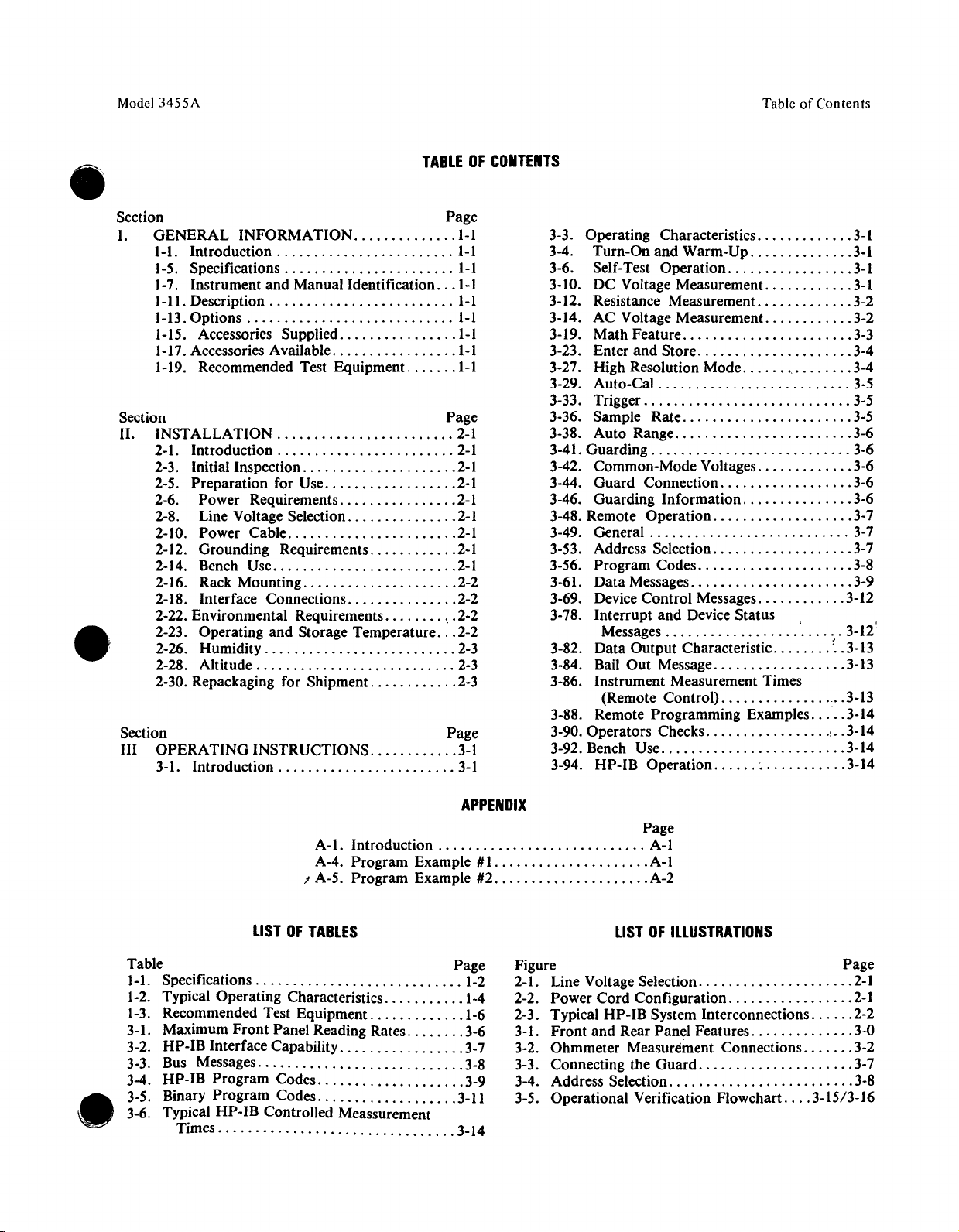
TABLEOFCONTENTS
•
•
Section Page
I. GENERAL INFORMATION 1-1
I-I.
Introduction I-I
1-5. Specifications I-I
1-7. Instrument and Manual Identification
I-II.
Description I-I
1-13.Options , I-I
1-15. Accessories Supplied
1-17.Accessories Available I-I
1-19. Recommended Test Equipment. 1-1
Section Page
II. INSTALLATION 2-1
2-1. Introduction 2-1
2-3. Initial Inspection 2-1
2-5. Preparation for Use 2-1
2-6. Power Requirements 2-1
2-8. Line Voltage Selection 2-1
2-10. Power Cable 2-1
2-12. Grounding Requirements 2-1
2-14. Bench Use 2-1
2-16. Rack Mounting 2-2
2-18. Interface Connections 2-2
2-22. Environmental Requirements 2-2
2-23. Operating and Storage Temperature 2-2
2-26. Humidity 2-3
2-28. Altitude 2-3
2-30. Repackaging for Shipment 2-3
Section Page
III OPERATING INSTRUCTIONS 3-1
3-1. Introduction 3-1
1-1
1-1
3-3. Operating Characteristics 3-1
3-4. Turn-On and Warm-Up 3-1
3-6. Self-Test Operation 3-1
3-10. DC Voltage Measurement. 3-1
3-12. Resistance Measurement. 3-2
3-14. AC Voltage Measurement. 3-2
3-19. Math Feature 3-3
3-23. Enter and Store 3-4
3-27. High Resolution Mode 3-4
3-29. Auto-Cal 3-5
3-33. Trigger 3-5
3-36. Sample Rate 3-5
3-38. Auto Range 3-6
3-41. Guarding 3-6
3-42. Common-Mode Voltages 3-6
3-44. Guard Connection 3-6
3-46. Guarding Information 3-6
3-48. Remote Operation 3-7
3-49. General 3-7
3-53. Address Selection 3-7
3-56. Program Codes 3-8
3-61. Data Messages 3-9
3-69. Device Control Messages 3-12
3-78. Interrupt and Device
Messages 3-12
3-82. Data Output Characteristic
3-84. Bail Out Message 3-13
3-86. Instrument Measurement Times
(Remote Control) 3-13
3-88. Remote Programming Examples 3-14
3-90. Operators Checks
3-92. Bench Use 3-14
3-94. HP-IB Operation
Status.
~
f• • 3-13
,..3-14
3-14
,
•
APPENDIX
A-I. Introduction A-I
A-4. Program Example #1. A-I
I A-5. Program Example #2
LISTOFTABLES
~k
I-I. Specifications 1-2
1-2. Typical Operating Characteristics 1-4
1-3. Recommended Test Equipment. 1-6
3-1. Maximum Front Panel Reading Rates 3-6
3-2. HP-IB Interface Capability 3-7
3-3. Bus Messages 3-8
3-4. HP-IB Program Codes 3-9
3-5. Binary Program Codes 3-11
3-6. Typical HP-IB Controlled Meassurement
Times··········.·.·
h~
3-14
Page
..
, A-2
LISTOFILLUSTRATIONS
Figure Page
2-1. Line Voltage Selection 2-1
2-2. Power Cord Configuration 2-1
2-3. Typical HP-IB System Interconnections 2-2
3-1. Front and Rear Panel Features 3-0
3-2. Ohmmeter
3-3. Connecting the Guard 3-7
3-4. Address Selection 3-8
3-5. Operational Verification Flowchart 3-15/3-16
Measurement Connections 3-2
Page 6
----------(hp]
~i~.z:~6
Herstellerbescheinigung
----------....,
•
Hiermit
in
Der
die
Zusatzinformation
Werden
verwendet,
Betriebsbedingungen an seiner GrundstGcksgrenze eingehalten
This is to
is in
man
the
Additional
If
measurements on open set-ups,
Interference
wird
bescheinigt,
Obereinstimmung
Deutschen
Berechtigung
accordance
Bundespost
series
Test- and
Bundespost
fur
Mefj-
und
so
ist
certify
for
compliance
Information
Measurement
Limits
zur UberprUfung der Serie
with
was
dafj
das
Gerat/Svstern
mit
den
Bestimmungen
wurde
das Inverkehrbringen dieses Gerates/Svsterns angezeigt und
Mefj-
und
Testgeriite
Testqerate
vom
that
the
the
notified
for
Test-
are still
mit
ungeschirmten
Betreiber sicherzustellen,
Manufacturer's
equipment
Radio
Interference
that
this
with
the
requirements
and
Measurement
Equipment
the
user hastoassure
metatthe
von PostverfGgung
auf
Einhaltung
Kabeln
dafj
declaration
.:....H:.:..P_3=....:4.::5.::5.:....A:...-
RequirementsofDirective
equipment
Equipment
is operated
border
was
was
of his premises.
und/oderinoffenen
die
put
granted.
with
unscreened cables
that
under
..:...H.:..:.P-=3-.:4..::5..::5:..:.A.:..-.
der
Funk-Entstorbestimmungen
into
1046/84
Bestimmungen
werden.
circulation,
operating
funkentstdrt
FTZ
1046/84.
the
conditions
ist.
elnqeraumt.
Mefjaufbauten
unter
The Ger-
righttocheck
and/or
used
the
Radio
_
_
•
for
NOTICE
The information contained in this document is subject to change without notice.
HEWLETT-PACKARD MAKES NO WARRANTY OF ANY KIND WITH REGARD TO THIS
MATERIAL, INCLUDING, BUT NOT LIMITED TO,
CHANT
be liable for errors contained hereinoffor incidental or consequential damages in connection with
the furnishing, performance or useofthis material.
Hewlett-Packard assumes no responsibility for the use or reliabilityofits software on equipment that
is not furnished by Hewlett-Packard.
This document contains proprietary information which is protected by copyright. All rights are
reserved. No
gram language without the prior written consentofHewlett-Packard Company.
ABILITY AND FITNESS FOR A PARTICULAR PURPOSE. Hewlett-Packard shall not
partofthis document may be photocopied, reproduced or translated to another pro-
THE
IMPLIED WARRANTIES OF MER-
Page 7
•
The
following
Failuretocomply
manufacture,
comply
to
general
and
with
with
intended
these
safety
precautions
these
precautions
use
of the
requirements.
~~
mustbe
orwith
instrument.
This is a Safety
observed
specific
Hewlett·Packard
~i~KL:~6
SAFETY
SUMMARY
during
all
phasesofoperation,
warnings
Class1instrument.
elsewhere
Company
in this
assumes
service,
manual
violates
no liability for the
and
repairof this
safety
instrument.
standardsofdesign,
customer's
failure
•
GROUND
To
The
ed
with
The
safety
DO
Do
instrumentinsuchanenvironment
KEEP
Operating personnel
must
nected.
avoid injuries,
DO
Do
resuscitation,
DO
Becauseofthe
unauthorized
vice
THE
INSTRUMENT
minimize
instrument
intoanapproved
the
power
NOT
not
AWAY
NOT
not
NOT
Office
shock
hazard,
is equipped
grounding
jack
standards.
OPERATEINAN
operate
FROM
be made by qualified
Under
SERVICEORADJUST
attempt
SUBSTITUTE
wire
and
the
LIVE
certain
always
internal
is present.
PARTSORMODIFY
dangerofintroducing
modificationtothe
for
service and repairtoensure
the
instrument
withathree-conductoracpower
three-contact
(green)
mating
EXPLOSIVE
instrumentinthe
CIRCUITS
must
conditions,
disconnect
firmly
plugofthe
ATMOSPHERE
not
remove
maintenance
ALONE
service or
chassis and
electrical
connectedtoan electrical ground (safety ground) at
presenceofflammable
constitutesadefinite
instrument
dangerous
power
adjustment
INSTRUMENT
instrument.
outlet
power
additional hazards, do
cable
personnel. Do
voltages
and discharge
unless
Return
that
or used
meet
covers.
the
safety
cabinet
may
another
mustbeconnectedtoan electrical
cable. The
withathree-contacttotwo-contact
International
gases or
safety
Component
not
replace
exist
circuits
person, capableofrendering
not
instrumenttoa
features
power
Electrotechnical
fumes.
hazard.
replacement and internal
components
even
with
before
install
are maintained.
cable
the
touching
substitute
Hewlett-Packard
must
either
the
power
Commission
Operationofany
adjustments
with
power
power
cable
removed.
them.
first
partsorperform
Sales and Ser-
ground.
be plugg-
adapter
outlet.
(IEC)
electrical
cable
aid and
con-
To
any
•
DO
NOT
OPERATEADAMAGED
Wheneveritis possible
either
through
use
the
instrument
the
instrument
features
DANGEROUS
Warnings, such as
Instructions
physical
until
to a
Hewlett-Packard
are maintained.
PROCEDURE
the
containedinthe
Dangerous
tion
when
voltages,
handling,
INSTRUMENT
that
the
damage,
safe
operation
WARNINGS
example
warnings
capableofcausing
testing,
safety
below,
protection
excessive
can be
Sales and Service
precede
mustbefollowed.
and
adjusting.
features
moisture,
verified
potentially
WARNING
death,
are
built
into
this
instrument
or any
present
other
reason, REMOVE POWER and do
by service-trained personnel.Ifnecessary,
Office
for
service and repairtoensure
dangerous procedures
in this
instrument.
Use
have
throughout
extreme
cau-
been impaired,
this
that
not
return
safety
manual.
A
Page 8
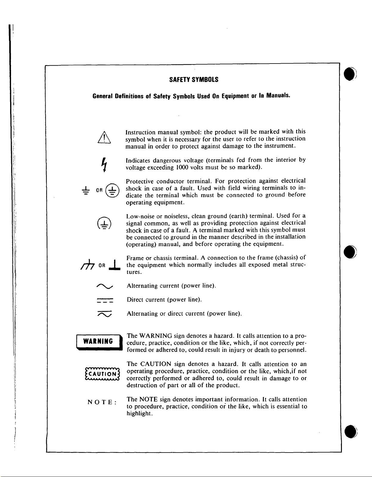
SAFETY
SYMBOLS
-:-
m
General
OR
@
ORJ.
DefinitionsofSafety
Instruction manual symbol: the product will be marked with this
symbol when it is necessary for the user to refer to the instruction
manual in order to protect against damage to the instrument.
Indicates dangerous voltage (terminals fed from the interior by
voltage exceeding 1000 volts must be so marked).
Protective conductor terminal. For protection against electrical
shock in case
dicate the terminal which must be connected to ground before
operating equipment.
Low-noise or noiseless, clean ground (earth) terminal. Used for a
signal common, as well as providing protection against electrical
shock in case
be connected to ground in the manner described in the installation
(operating) manual, and before operating the equipment.
Frame or chassis terminal. A connection to the frame (chassis)
the equipment which normally includes all exposed metal struc-
tures.
Symbols
of
a fault. Used with field wiring terminals to in-
of
a fault. A terminal marked with this symbol must
UsedOnEquipment
or In
Manuals.
of
•
;:::;:::;
WARNING
I
NOTE:
Alternating current (power line).
Direct current (power line).
Alternating or
The WARNING sign denotes a hazard. It calls attention to a pro-
cedure, practice, condition or the like, which, if not correctly per-
I
formed or adhered to, could result in injury or death to personnel.
The
CAUTION
operating procedure, practice, condition or the like, which,if not
correctly performed or adhered to, could result in damage to or
destruction
The NOTE sign denotes important information. It calls attention
to procedure, practice, condition
highlight.
direct
current
sign denotes a hazard.Itcalls attention -to an
of
part
or allofthe product.
(power line).
or the like, which is essential to
•
Page 9
Model
3455A
Section I
•
'.
SECTION
GENERAL
1-1.
INTRODUCTION.
1-2. This Operating and Service Manual contains information necessary to install, operate, test, adjust, and service
the Hewlett-Packard Model 3455A Digital Voltmeter.
1-3. Included with this manual is an Operating information
supplement. The supplement is a duplication
three sections
instrument for use by the operator.
1-4. This section
specifications and general operating characteristics
3455A. Also listed are available options and accessories,
and instrument and manual identification information.
1-5.
SPECIFICATIONS.
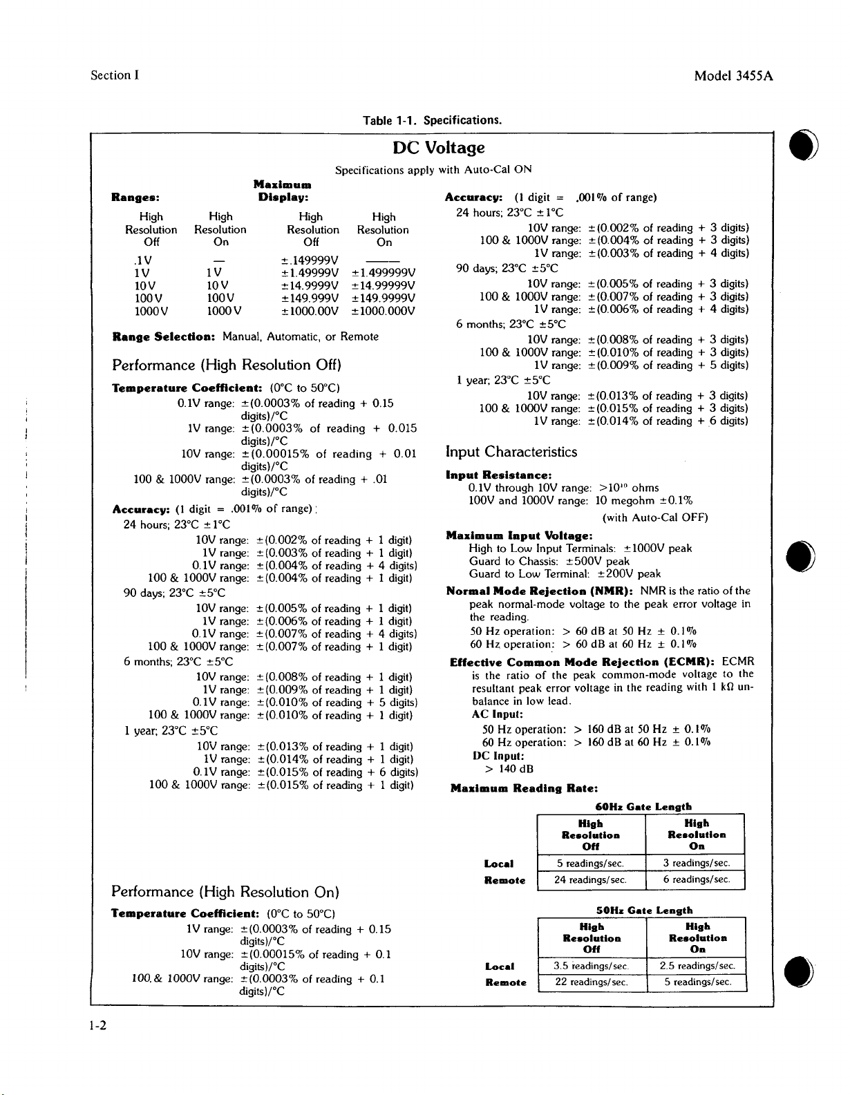
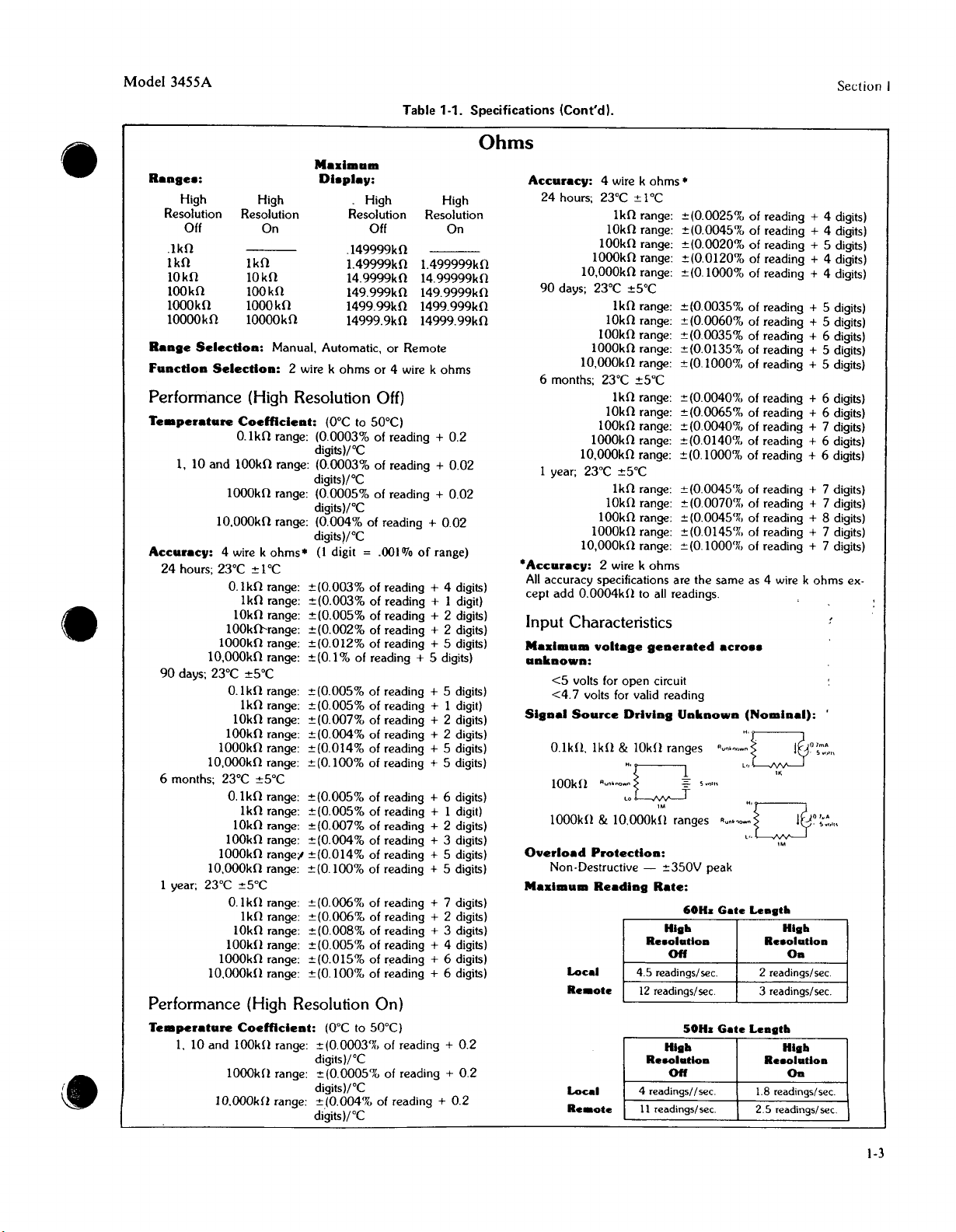
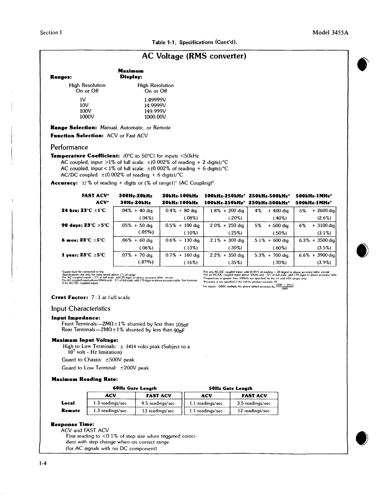
1-6. Operating specifications for the 3455A are listed in
Table
I-I.
dards or limits against which the instrument is tested. Table
1-2 lists general operating characteristics
These characteristics are
operating characteristics included as additional information
for the user.
1-7.
INSTRUMENT
1-8. Instrument identification by serial number is located
on the rear panel. Hewlett-Packard uses a two-section serial
number consisting
suffix separated by a letter designating the country in
which the instrument was manufactured. (A = U.S.A.;
G
=West Germany; J =Japan; U =United Kingdom.) The
prefix is the same for all identical instruments and changes
only when a major instrument change is made. The suffix,
however, is assigned sequentially and is unique to each
instrument.
of
this manual and should be kept with the
of
the manual contains the performance
These specifications are the performance stan-
not
specifications
AND
MANUAL
of
a four-digit prefix and a five-digit
I
IOENTIFICATION.
of
the first
of
the instrument.
but
are typical
of
the
I
INFORMATION
age measurements with five digit resolution and de voltage
and resistance measurements with 5 or 6 digit resolution as
programmed by the user. The 3455A employs an automatic
calibration (AUTO CAL) feature which automatically cor-
rects for possible gain and offset errors in the analog circuitry to provide maximum accuracy. A removable reference module permits external calibration
and resistance functions. The reference module can be
removed, calibrated and returned to the instrument, or the
module can be replaced with another recently calibrated
reference. A MATH feature permits voltage or resistance
measurements to be scaled into convenient units or to be
read directly in percent error from a selected reference.
The 3455A is HP-IB programmable for system applications.
HP-IB is Hewlett-Packard's implementation
IEEE
std
488-1975. "standard digital interface
for programmable instrumentation ".
1·13.
OPTIONS.
1-14. The following options are available for use with the
Model 3455A:
Option 001: Average Responding ACConverter
Option 907: Front Handle Kit
Option 908: Rack Mounting Kit
Option 909: Front Handle and Rack
Option 910: Additional Set
and Operating and Service Manuals
1-15.
Accessories
1-16. A service kit (-hp- Part No. 03455-84411) consisting
of a PC extender board and a fuse is supplied with the
Model 3455A.
1·17.
ACCESSORIES
Supplied.
NOTE
of
AVAILABLE.
of
Mounting Kit
Operating Information
the de voltage
of
•
1-9. This manual applies to instruments with serial num-
bers indicated on the title page. If changes have been made
in the instrument since this manual was printed, a yellow
"Manual Changes" supplement supplied with the manual
will define these changes and explain how to adapt the
manual to the newer instruments. In addition, backdating
information contained in Section
instruments with serial numbers lower than those listed on
the title page.
1-10. Part numbers for the manual and the microfiche
copy
of
the manual are also listed on the title page.
1·11.
DESCRIPTION.
1-12. The Model 3455A Digital Voltmeter makes ac volt-
vn adapts the manual to
1-18. The following is a list
with the Model 3455A.
Accessory No. Description
1II77A
3411IA
10631A
10631B
10631C
1-19.
Recommended
1-20. Equipment required to maintain the Mode13455A is
listed in Table 1-3. Other equipment may be substituted if
it meets the requirements listed in the table.
3455A Reference Module
High Voltage Probe (40 kV de)
HP-IBCable
HP-IBCable 2 meter (78.74 in.)
HP-IBCable 4 meter
Test
Equipment.
of
accessories available for use
I meter (39.37 in.)
(I
57.48 in.)
1·1
Page 10
Section
I
Ranges:
High
Resolution
Off
.1V ±.149999V
IV
lOV
100V
1000 V
Range
Performance
Temperature
100 & 1000V range:
Accuracy:
24 hours; 23°C
90 days; 23°C ±5°C
6 months; 23°C
I year; 23°C
Performance
Temperature
100.& 1000V range:
1-2
Specifications apply with Auto-Cal
Mallimum
Display:
High
Resolution
On
IV
lOV
100 V
1000 V
Selection:
O.lV range:
(I digit =
100
& 1000V range:
100
& 1000V range:
100
& 1000V range: ±(0.01O% of reading + 1 digit)
100
& 1000V range: ± (0.015% of reading + I digit)
lOV range:
Manual, Automatic, or Remote
(High
Coefficient:
IV range:
lOV range: ±
lOV range:
0.1V range:
lOV range:
O.lV range:
lOV range: ± (0.008% of reading + 1 digit)
0.1V range:
±5°C
lOV range:
O.lV range:
(High
Coefficient:
IV range:
.00111fo
± 1°C
1V range:
IV range:
±5°C
1V range:
IV range:
Resolution
±(0.0003%
digitslf"C
±(0.0003%
digitslf"C
(0.00015%
digitslf"C
±(0.0003%
digits)/"C
±(0.002%
± (0.003% of reading + 1 digit)
± (0.004% of reading + 4 digits)
±(0.004%
±(0.005%
±(0.006%
±(0.007%
±(0.007%
± (0.009% of reading + 1 digit)
± (0.010% of reading + 5 digits)
Resolution
±(0.0003%
digits)j"C
±(0.00015%
digitslf"C
±(0.0003%
digitslf"C
High
Resolution Resolution
Off On
±1.49999V
±14.9999V
±149.999V ±149.9999V
±1000.00V
±1.499999V
±14.99999V
±lOOO.OOOV
Off)
(O°C
to 50°C)
of reading + 0.15
of reading + 0.015
of reading +
of reading + .01
of range):
of reading + 1 digit)
of reading + 1 digit)
of reading + 1 digit)
of reading + 1 digit)
of reading + 4 digits)
of reading + 1 digit)
±(0.013%
±(0.014% of reading + 1 digit)
±(0.015%
of reading + 1 digit)
of reading + 6 digits)
On)
(O°C
to 50°C)
of reading + 0.15
of reading + 0.1
of reading + 0.1
Table 1-1. Specifications.
DC Voltage
Accuracy:
High
0.01
24 hours; 23°C
100
90 days; 23°C
100
6 months; 23°C
100
1 year; 23°C
100
Input
Characteristics
Input
Resistance:
0.1V through lOV range: >10'0 ohms
100V and 1000V range: 10 megohm
Mallimum
High to Low Input Terminals: ±1000V peak
Guard to Chassis:
Guard to Low Terminal:
Normal
peak normal-mode voltage to the peak error voltage in
the reading.
50 Hz operation: > 60 dB at 50 Hz ±
60 Hz operation: > 60 dB at 60 Hz ±
Effective
is the ratio of the peak common-mode voltage to the
resultant peak error voltage in the reading with I kU unbalance in low lead.
AC Input:
50 Hz operation: > 160dB at 50 Hz ±
60 Hz operation: > 160dB at 60 Hz ±
DC Input:
> 140 dB
Mallimum
Local
Remote
Local
Remote
Model 3455A
ON
(I
digit =
lOV range: ±(0.002% of reading
& 1000V range: ±(0.004% of reading + 3 digits)
±5°C
lOV range: ±(0.005% of reading + 3 digits)
& 1000V range:
lOV range: ±(0.008% of reading + 3 digits)
& 1000V range: ±(0.01O% of reading + 3 digits)
±5°C
lOV range: ±(0.013% of reading + 3 digits)
& lO00V range: ±(0.015% of reading + 3 digits)
Input
Mode
Rejection
Common
Reading
.OOII1foofrange)
± 1°C
IV range:
IV range: ±(0.006% of reading
±5°C
IV range:
IV range: ±(0.014% of reading
Voltage:
±(0.003%
±(0.007%
±(0.009%
±500V peak
±200V
(NMR):
Mode
Rate:
60Hz
High
Resolution
Off
5 readings!sec.
24 readings!sec.
50Hz
High
Resolution
Off
3.5
readings!sec. 2.5 readings!sec.
22 readings! sec. 5 readings!sec.
of reading + 4 digits)
of reading + 3 digits)
of reading + 5 digits)
±0.1%
(with Auto-Cal OFF)
peak
NMRis the ratio of the
0.111fo
0.1070
Rejection
Gate
Gate
(ECMR):
Length
Resolution
3 readings!sec.
6 readings!sec.
Length
Resolution
+ 3 digits)
+ 4 digits)
+ 6 digits)
0.1070
0.1070
High
On
High
On
•
ECMR
•
Page 11
•
•
•
Model 3455A
Range.:
High
Resolution
Off
.1kO
lkO
lOkO
100kO
ioooin
10000kO 10000kO
Range
Function
Resolution
IkO
lOkO
100kO
1000kO
Selection:
Selection:
High
On
MaxilDulD
Di.play:
Manual, Automatic, or Remote
2 wire k ohms or 4 wire k ohms
Performance (High Resolution Off)
Temperature
I, 10 and 100kO range: (0.0003% of reading + 0.02
Accuracy:
24 hours; 23°C
90 days; 23°C
6 months; 23°C
I year;
Coefficient:
O.lkO range: (0.0003% of reading
looOkO range: (0.0005% of reading + 0.02
10,OookO range: (0.004% of reading + 0.02
4 wire k
1000kO range:
lO,OOOkO
1000kO range: ±(0.014% of reading
lO'ooOkO range:
1000kO
1O,OOOkO
23°e
1000kO range:
1O.oo0kH range:
ohms.
:!:
1°C
O.lkO range:
IkO range: :!:(0.003% of reading + I digit)
lOkO range:
100kfr-range: :!:(0.002% of reading + 2 digits)
range: ±(O.I % of reading + 5 digits)
:!:5°C
O.lkO range:
IkO range: :!:(0.005% of reading + I digit)
lOkO range:
100kO range:
:!:5°C
O.lkO range: ±(0.005% of reading + 6 digits)
IkO range: :!:(0.005% of reading + I digit)
lOkO range:
100kO range:
rangel
range: ±(0.100% of reading + 5 digits)
-s-c
O.lkfl range: :!:(0.006% of reading + 7 digits)
IkO range: :!:(0.006% of reading + 2 digits)
lOkO range:
100kH range:
(O°C
digitslrC
digitslrC
digitslrC
digitslrC
(I digit = .001%
:!:(0.003% of reading + 4 digits)
:!:(0.005% of reading + 2 digits)
:!:(0.012% of reading + 5 digits)
:!:(O.OOS%
:!:(0.007% of reading + 2 digits)
:!:(0.004% of reading + 2 digits)
:!:
(0.100% of reading + S digits)
:!:(0.007% of reading + 2 digits)
:!:(0.004% of reading + 3 digits)
:!:(0.014% of reading + 5 digits)
:!:(0.008% of reading + 3 digits)
:!:(0.005% of reading + 4 digits)
:!:(O.OIS%
:!:(0.100% of reading + 6 digits)
Performance (High Resolution On)
Temperature
Coefficient:
(OOe
1. 10 and lOOk!! range: :!:(0.0003'l{, of reading + 0.2
lOookfl range: :!:(0.0005% of reading + 0.2
lO'ooOkfl range: :!:(O.004% of reading + 0.2
digitslrC
digitslrC
digitslrC
Table 1-1. Specifications (Cont'd).
High
Resolution Resolution
Off On
.149999kO
1.49999k0
14.9999kO 14.99999kO
149.999kO 149.9999kO
1499.99kO
14999.9kO 14999.99kO
to 50°C)
of reading + 5 digits)
of reading + 6 digits)
to 50°C)
High
1.499999k0
1499.999kO
+ 0.2
of
range)
+ 5 digits)
Ohms
Accuracy:
24 hours; 23°C
90 days; 23°C ±5°C
6 months; 23°C ±5°C
I year; 23°C ±5°C
·Accuracy:
All
accuracy specifications are the same as 4 wire k ohms ex-
cept add 0.0004kfl to all readings.
Input
MaxilDulD
unknown:
<5
<4.7
Signal
o.u.n
ioo,n
1000kH &
Overload
Non-Destructive - :!:350V peak
MaxllDum
4 wire k ohms •
IkO range: ±(O.0025% of reading + 4 digits)
lOkO range:
100kO range:
lOookO range:
lO,OOOkO
IkO range: :!:(0.0035% of reading + S digits)
lOkO range:
100kO range: ±(0.0035% of reading
1000kO range:
1O,000kO range:
IkO range: :!:(0.0040'X, of reading + 6 digits)
lOkO range:
100kO range:
1000kO range:
1O,000kO range: ±(O.lOoo% of reading
IkO range: :!:(0.004S% of reading + 7 digits)
lOkO range:
100kO range:
1000kO range:
lO,OOOkO
2 wire k ohms
Characteristics
voltage
volts for open circuit
volts for valid reading
Source
Ikfl
."".no~'D
1;.~OOk~;
Protection:
Reading
Local
Re.ote
Local
Re.ote
:!:
1°C
:!:(0.0045% of reading + 4 digits)
:!:(0.0020% of reading + 5 digits)
:!:(0.0120% of reading + 4 digits)
range: :!:(0.1000% of reading + 4 digits)
:!:(0.0060% of reading + 5 digits)
:!:(0.0135% of reading + 5 digits)
:!:
(0.1000% of reading + 5 digits)
:!:(0.0065% of reading + 6 digits)
:!:(0.0040% of reading + 7 digits)
:!:(0.0l40% of reading + 6 digits)
:!:(0.0070% of reading + 7 digits)
:!:(0.0045% of reading + 8 digits)
:!:(0.0145'l{, of reading + 7 digits)
range: :!:(0.1000% of reading + 7 digits)
generated
Driving
& lOkfl ranges
Rate:
HISh
Re.oladon
Off
4.5 readings/sec.
12 readings/sec.
Hish
Reaoladoa
Off
4 readings//sec.
11 readings/sec.
aero
••
Unknown
(NolDlnal):
R"".rn,·:'OO~";~".
s."". L" lK
ranges
.""'~:Oo~:.,,,.
60H.
Gate
Lensth
2 readings/sec.
3 readings/sec.
SOH.
Gate
Leasth
1.8 readings/sec.
2.5 readings/sec.
+ 6 digits)
+ 6 digits)
Hish
Re.olatloa
Oa
HISh
Reaolatloa
On
Section
1-3
I
Page 12
Section I
Ranges:
Range
func:tion
Performance
Temperature
AC coupled, input
AC coupled,
AC/DC
Ac:c:urac:y:
Table 1-1. Specifications [Cont'd].
AC Voltage (RMS converter)
Maximum
Display:
High Resolution
On or Off
IV
lOV
l00V
l000V
Selec:tion:
Selec:tion:
Manual, Automatic, or Remote
ACV or Fast ACV
Coefflc:ient:
>1%
input
of full scale: ±(O.002% of reading + 2 digitsll"C
< 1% of full scale: ±(O.002% of reading + 6 digitsll"C
coupled: ±(O.002% of reading + 6 digitsll"C
±r%
of reading + digits or (% of range) I' (AC Coupling)'
High Resolution
On or Off
1.49999V
14.9999V
149.999V
lOOO.OOV
(O°C to 50°C) for inputs
Model 3455A
<50kHz
24
hr.;
FAST ACV·
ACV·
23°C
:!:1"C
300Hz-20kHz
30Hz-20kHz
.04%
+ 40 dig. 0.4% + 80 dig. 1.8% + 200 dig.
(.04%) (.08%) (20%)
90
da".;
23°C
:!:5°C
.05%
+ 50 dig.
(.050/0)
.06%
+ 60 dig. 0.6% + 130 dig. 2.1% + 300 dig.
(.06%) (.13%) (.30%)
I
"ear;
23°C :!:5°C
.07%
+ 70 dig. 0.7% + 160 dig. 2.2% + 350 dig. 5.3%
(.07%)
'Guard
musl
be
connected
Speciftceucns
For AC
For AC
2 for ACI DC coupled mputs
Crest
fac:tor:
coupled
coupled
10 low
ete only for input levels
inpuls .
l't.
of full scete add 20 digits/0ebove
inpuls
~bove
50kHz
7:
1 at full
and .
ebove
S·~,
I'\. of
range
of full scale add
scale
accuracy
teble
170digits'0above
Input Characteristics
Input
Impedanc:e:
Front
Terminals-2Mfl±
Terminals-2Mfl:!:1%shunted
Rear
Maximum
Input
Voltage;
High to Low Terminals: ± 1414 volts peak (Subject to a
107volt - Hz limitation)
Guard
to Chassis:
Guard
to Low Terminal:
±500V
1%
peak
±200V
shunted
peak
by less than 105pF
by less than 90pF
20kHz-100kHz
20kHz-100kHz
0.5%
+ 100 dig.
(.10%) (.25%)
(.16%) (.35%)
except
accuracy tebte
See
footnote
100kHz-250kHz'
100kHz-250kHz'
+ 250 dig. 5% + .s00 dig.
2.0%
'For any
AC,DC
an
ACtDC
of
IS nOI specifiold ifthl:'
inputs
"SOOv. mulriply the
coupled
coupled
grl?~ler
than
For
'Frequencies
'Accuracy
For
250kHz-500kHz'
250kHz-500kHz'
inpul
add
(Q OS't. of reading
mput
above
SOkHz
100kHz
oUt'
voll·hz
product
above
rebled
+ 400 dig.
4%
(.40%)
(.50%)
+ 600 dig. 6.3%
5.1%
(.60%)
+ 700 dig.
(.70%)
~
20
and,
S',;, of lull scale add 170 d,glls 10
specrtred lor the IV
exceeds
10'
accur"cy
by
1~~Vinl
digilsllo
and
IOV r",ngl!Sonly
ebove
500kHz-IMHz'
500kHz-IMHz'
+ 2600 dig.
5%
(2.6%)
+ 3100 dig.
6%
(3.1%)
+ 3500 dig.
(3.5%)
+ 3900 dig.
6.6%
(3.9%)
."curacy
lablto. excepe
above
eccorecv
tebl
....
1-4
Mallimum
Local
Remote
Response
ACV
and
First reading to
dent
(for AC signals with
Reading
Time:
FAST ACV
with step
Rate:
60Hz
ACV
1.3 readings/sec.
1.3 readings/sec.
<0.1
% of step size
change
when
noDCcomponent)
Gate
Length
FAST ACV
4.5 readings/sec.
13 readings/sec. 1.1 readings/sec.
when
triggered coinci-
on correct range.
50Hz
Gate
Length
ACV FAST ACV
1.1 readings/sec.
3.5 readings/sec.
12 readings/sec.
•
Page 13

Model
3455A
Section I
•
•
Ranges:
High Resolution
On or Off
IV
lOV
l00V
1000V
Range
Function
Selection:
Selection:
Performance
Temperature
±(0.002%
Accuracy:
24
90
6
I
±[% of reading + digits or (% of range) ] I
hra:
23°C ±r-c
dap:
.0.:
23°C ±5°C
p.:
23°C ±5°C
Table 1-1. Specifications
AC Voltage (Average Converter Opt. 001 )
Mallimum
Display:
Manual, Automatic, or Remote
ACV or Fast ACV
Coefficient:
of reading + 2 digitslrC
FAST
ACV'
ACV
23°C ±5°C
(O°C
300Hz·500Hz
3
30H.·50Hz
0.47% + 70 dig. 0.32% + 50 dig. 0.09% + 25 dig.
0.50%
0.50%
0.50%
'Guard
must be connected 10 Low
On 1M
lOOOV
Specificalions are for input
'Frecceoces
greater than 100kHz
'AcCUf<llCY
is not
ICont'd)
High Resolution
On or Off
1.
49999V
14.9999V
149.
999V
1000.00V
to 50°C)
500H.·IkHz
50Hz.IOqHz
(.07%)
+ 70 dig. 0.35% + 50 dig. 0.1%
(07%) (05%)
+ 70 dig. 0.40% + 60 dig. 0.1% + 30 dig.
(.07%) (.06%) (.03%) (.07%)
+ 70 dig. 0.40% + 70 dig. 0.12% + 35 dig.
(.07%) (.07%) (.035%)
rall¥.
add 0.01 ppm/vol! • kHz
lewis
above
if the
s~cified
von-bene
s~cifled
(05%)
l/l00ch of
111"9"
on I and lOVranges only
product
exceeds
10'
.
1kHz·
100kHz
IOOH.·IOOkHz
(.025%) (.06%)
+ 25 dig. 0.75% + 60 dig.
(.025%) (.06%)
IOOkHz·250kHz'
IOOkHz·250kHz'
0.70%
0.75%
0.75%
+ 60 dig.
+ 70 dig.
+ 80 dig.
(08%)
•
Input Characteristics
Input
Impedance:
Front
Terminals-2MO
Rear
Terminals-2MO
Mallimum
Mallimum
Response
Input
High to Low ']derminals: ± 1414 volts peak (Subject to a
7
10
volt - Hz limitation)
Guard to Chassis:
Guard to Low Terminal: ±200V peak
Loca.
Re.ote
ACV and FAST ACV
First reading to <0.1% of step size when triggered coincident with step change when on correct range .
(for AC signals with no DC component)
Voltage:
Reading
1.3 readings/sec.
1.3 readings/sec.
Time:
±1% shunted by less than 105pF
±1% shunted by less than 90pF
±SOOV
peak
Rate:
60Hz
Gate
Leagth
ACV
FASTACV
4.5 readings/sec.
13 readings/sec.
50Hz
ACV
1.1 readings/sec.
1.1 readings/sec.
Gate
Leagth
FASTACV
3.5 readings/sec.
12 readings/ sec.
1-5
Page 14

Section I
Model 3455A
Table 1-1. Specifications
(Cont'd].
Math
Scale:
Madmum
Accuracy:
NORMAL
!!
~
.'
NORMAL
(X
~
z)
X is present reading. Y
ings, numbers entered from the front panel or values entered
by external program.
Number:
and
2 are previously entered read-
(Entered or Displayed)
±199,999.9
±(ACCURACY OF X READING ±1 DIGIT OF DIS-
PLAYED
'This assumes no "Y" or
ANSWERjI
"2"
error.
Table 1-2. Typical Operating Characteristics.
Range
Selection:
Function
DC Volts
AC Volts
OHMS
TeST
70
601-----.+---.++++1-++1--+-++11-++++l--+++-H
50
;;;
s
40
z
0
30
i
20
10
70
60
1---.jf.--l-1--H++IH--I-H+I-++H---t--t-Jf-H
50 1----I1-1-+-H-H-Ir+--t-H+hlt+H--t--t-H-i
Normal Mode
Selection:
(ACVor
(2 wire
MODE
GOIGH
OPE
U
MODE
6
DIGIT
OPEAt~
Manual,
FAST
kilohm
or 4 wire kilohm)
REJECTION
"Y
5 DIGIT [;.::
/
IPrIERA~
10 100
REJECTION
10 100
Rejection
Automatic,orRemote
ACVI
(50HzOPERATION)
/,
~
L"v
FA€QUENCY
IHll
(60HZOPERATION)
FREOUENCY
(Hzl
11
= 20 log
f T I
--sin 11f T
1
"
"
~~
~
% Error:
Maximum
(X~Y)
X is present reading. Y is a previously
numberentered fromthe front panel or by external program.
Nu.ber:
x 100%
entered
(Entered or Displayed)
±199,999:9
Accuracy:
±(ACCURACY OF X READING ± 1 DIGIT OF DIS-
PLAYED ANSWER)'
'This assumes no "Y" error.
Effective Noi58
T =
T =
T =
COMMON
EFFECTIVE
T =
MODE
ISO .
140
I--kd:-l..j-j-,fffi-~H+J-+++H--+-+Ht-Htt--Hi
130
~
120
z
0
"0
i
100
90
.0
COMMON
180 .
1701--++-1+
160
150
140
130
120
110
Bandwidth
1/00
sec for 5 .digit 00 Hz
2/15
sec for 6 digit 60 Hz
1/50
sec for 5 digit 50 Hz
4/25
secfor 6
REJECTION
t-,
r-,
FREQUENCY
MODE
di~it
REJECTION
60lGI1
OPERATION
I'-.
r-.
1
= 2T
Operation
Operation
Operation
50 Hz
Operation
(1
KILOHM
1'-,
r-,
10 100
1Hz!
(50HzOPERATION)
~I
SOIGIT
OPERATION
"'-f--
10
FREOUENCY
IHII
IMBALANCE)
r-.
reading, or
•
r-,
!I'
~W
100
1-6
•
Page 15

•
Model
EFFECTIVE
3455A
180
~
z
o
140
i
120
COMMON
170
160
150
130
110
MODE
REJECTION
6 DIGIT
~ERATION
I"
table
1-2. Typical Operating Characteristics
(60HzOPERATION)
~~I
NATiOJ
JI
10 100
FREQuENCY
lHzl
General
Overload
Operating
Warmup
Humidity
Storage
Power:
Dimensions:
Weights:
(Cont'd)
(Auto
specifications)
Indication:
Temperature:
Time:
Range: < 95% R
Temperature:
100/120/240
operation<60
220
<60VA
Net
Shipping
.
Cal
must
OL
One
hour
V +5%,
V ± 10%48Hzto400
88.9
mm
mm
deep
- 9 kg (21 lbs.l
- 12 kg (26 lbs.l
be 'on
OOCto50°C
to
mee~
6H.,
-40
C to +75 C
VA
high x
(3'1,"
high x 16'%"
Section I
for75secondstomeet
all
spec~fications
0 C tg40C
-10%
48 Hzto400
Hz line
operation
425.5
mm
widex527.1
wide
x 20'%"
all
Hz line
deep)
•
Typical HP-IB
Accept
500
Output
250
1-21.
SAFETY
Handshake
Data -
Data -
per
(3455A
character
(3455A
character
/lsec per
usee
CONSIDERATIONS.
Times:
addressed
typical(0delay
addressedtotalk)
typical (0
to listen or ATN
delay
source)
true)
acceptor)
1-22. The 3455A is a safety class I instrument (provided
with a protective
earth
terminal). The instrument and manual should be reviewed for safety symbols and instructions
before operation.
I
fA
~
1-7
Page 16

Section I
Instrument
DC Voltage
AC Calibrator
Standard
Table 1-3. Recommended Test Equipment.
Critical Specification
Voltage: 10 mVto1000
Accuracy: ± .005%
Frequency:
Output
Accuracy: ± .1% -hp- Model
Voltage Stability (6 mos.l ± .02% High Voltage Amplifier
Level:
20 Hz to
100
V
100
kHz -hp- Model
mVto1000
V
Recommended
Systron
Model
Calibrator
AC
Model
Donner
Ml07
745A
746A
Model 3455A
Use
PAT
PAT
Test Oscillator
Resistance Decade
Voltmeter
DC Null
Reference
DC Transfer
Electronic
Resistance
Bus
Calculator
Oscilloscope
Digital
System
Voltmeter
Divider
Standard
Counter
Standard
Analyzer
Frequency:to250
Output:
Resistance:
Output
Stability:
50Hzto
Accuracy: ± .0005%
Accuracy:
Sweep
Sensitivity: 1 V/div
Voltage Range: 10 mV to
Resolution:10J,lV
3 V rms
Frequency
Accuracy: ± .004% GR 1433-Z Decade
Voltage Range: 1
Ratio
Division
Voltage Range - 1 Vto1 kV
Output
Voltages; 1 V,
1.019\1,10
Accuracy: ± 5
Resistance:
Resistance:
HP-IB Control Capability
HP·JB Control Capability
serve as
Output
Bandwidth:DCto
± .001% (30 days)
60 Hz
printer
data.
Time: 0.1
kHz
into
Response ± .25%
100
1
100
±
50 n
n to 10
Mn
J.lV
to 10 V
Accuracy ± .001 %
ppm
kn
K
.002%
for
J,lS
1.018
must
3455A
10 MHz
to 1 sec/div
V
1000
Model
Model
K or
System
652A
419A
750A
731A
Standard
5300A/5302A
System
9330A/l
9330/100
Analyzer
9825A
180C/D
with
1821A
3490A
-hp- Model
Test Oscillator
Gen Rad Model
Resistor
-hp- Model
Fluke
Reference Divider
V,
V
Fluke
DC Transfer
-hp- Model
Measuring
Guildine Model
9330/1
Guildline Model
-hp- Model 59401 A
Bus
-hp- Model
-hp- Model
Oscilloscope
1801Aand
plug-in units
-hp- Model
P
PAT
PAT
PA
PA
P
A
K
K
T
•
OT
T
PAT
1-8
Resistors
Signature Analyzer
P =
Performance
=
Adjustments
A
Checks
Resistances:
1kn± 10%
kn
± 0.1%
10
Mn
±0.1%
1
T =
Troubleshooting
o =
Operators
Check
-hp- Part No.
0684-1021
0698-4157
0698-6369
-hp- Model
5004A
P
T
•
Page 17

Model
3455A
Section II
•
•
SECTION
INSTALLATION
2-1.
INTRODUCTION.
2-2. This section contains information and instructions
necessary to install and interface the Model 3455A
Digital Voltmeter. Also included are initial inspection
procedures, power and grounding requirements, environmental information, and repackaging instructions.
2·3.
INITIAL
2-4. This instrument was carefully inspected both
mechanically and electrically before shipment.
be free
order. The instrument should be inspected upon receipt
for damage that might have occurred in transit.
shipping container or cushioning material is damaged, it
should be kept until the contents
been checked for completeness and the instrument has
been mechanically and electrically checked. Procedures
for testing electrical performance
in Section IV.
mechanical damage or defect, or if the multimeter does
not pass the Performance Tests, notify the nearest
Hewlett-Packard Office. (A list
Service Offices is presented at the back of the manual.)
If
the shipping container is damaged, or the cushioning
material shows signs of stress, notify the carrier as well
as the Hewlett-Packard Office. Save the shipping
materials for the carrier's inspection.
2-5.
PREPARATION
2·6.
Power
2-7. The Model 3455A requires a power sourceof100,
120, 220, or 240 V ac
single phase. Maximum.
2·8.
Line
2-9. Before connecting ac power to the 3455A, make
sure the rear panel line selector switches are set to correspond to the voltage
shown in Figure 2-1. Also, be sure the proper fuse
stalled. The multimeter is shipped with the line voltage
and fuse selected for 120 V ac operation.
INSPECTION.
It
of
mars and scratches and in perfect electrical
of
the shipment have
of
the 3455A are given
If
the contents are incomplete, if there is
of
the -hp- Sales and
FOR
USE.
Requirements.
(+
Voltage
5070-10%),48
pooler consumption is 60 VA.
Selection.
of
the available power
Hz to 400 Hz
should
If
the
li~e.
as
IS
10-
II
220V 220V
40V~~40V~
lDO\' IOOV
~
120 120V
240VOlh
220\1
40V~~40~
@
KlOV KlOV
120V 120V
120 Volls 100 Volli
NOMINAL OPERATING RANGE
VOLTAGE
100
volts
120
volts
220
volts 198 to 231 volts
240
volts
2·10.
Power
2-11. Figure 2-2 illustrates the standard configurations
used for -hp- power cables. The -hp- part number
directly below each drawing is the part number for a
power cable equipped with a connector
figuration.
cluded with the instrument, notify the nearest -hp- Sales
and Service Office and the proper cable will
vided.
2·12.
Grounding
2-13. To protect operating personnel, the National
Electrical Manufacturer's Association (NEMA) recom-
mends that the instrument panel and cabinet be
grounded. The Model 3455A is equipped with a three
conductor power cable which, when plugged into an appropriate receptacle, grounds the instrument.
2-14.
Bench
2-15. The Model 3455A is shipped with plastic feet and
tilt stands installed and is ready for use as a bench instrument. The plastic feet are shaped to permit "stacking"
with other full-module Hewlett-Packard instruments. The tilt stands permit the operator to elevate
the front panel for operating and viewing convenience.
-
10%,
90 to
108
216to252
Figure
2·1.
Line
Cable.
If
the appropriate power cable is not in-
Requirements.
Use.
220
Volts
220V
+5% of nominal FUSE
105
volts
to 126 volts
volts
Voltege
Selection.
.
0.5
0.5
0.25
0.25
of
that con-
A
A
A
A
be pro-
Be sure the 50 - 60 Hz rearpanel switch is
set
for
the proper line frequency
for
your
location.
2-16.
Rack
Mounting.
2-17. The Model 3455A may be rack mounted by adding rack mounting kit Option 908or Option 909. Option
908 contains the basic hardware and instructions for
2-1
Page 18

Section II
Model 3455A
POWER CORDS
@
AUSTRALIA
Powercords supplied by HP havepolarities matched to the power input socket on the instrument:
NOTE: Plugs are viewed from connector end. Shape of molded plug may vary within
• CSA certification includes only these Power Plugs
rack mounting;
basic rack
to permit the Multimeter to be installed in a
inch rack. When rack mounting, additional
must be provided at the rearofthe
that
unobstructed.
2·18.
2-19. The Model 3455A is compatible with the HewlettPackard
mount
the
air
Interface
Interface Bus (HP-IB).
• •
e:
E3
•
DENMARK
• L
= Line or Active Conductor (also called
• N
=Neutral
• E
=Earth or Safety Ground
Option
intake
Connections.
kit.
The
at the rear
NOTE
909
rack
N L
G3
EUROPE
Country Part Number Opt. Voltage
Australia 8120-1369
Denmark
Europe
Great Britain
Switzerland
"United States
"United States
or
Identified Conductor
Figure
adds
front
handles to the must not exceed 2 meters (6.5
mount
kits
are
instrument. Be sure
of
the instrument is
L N
• •
G!lJ
GREAT
8120·2956 912 250V 6A
8120-1689 902 250V 6A
8120-1351
8120-2104 906 250V 6A
8120-1378
8120-0698 904 240V 10A
2·2. Power
designed instruments to be connected,or20 meters (65.6 ft.),
standard
support
[Q]
~N'
~
BRITAIN
"live"
Cord
19 whichever is less.
2-20. Address Selection.
located on the rear panel, permits the user to set the
"talk"
and
vide a unique address for each bus instrument.
3455A normally leaves
switch set to a
dress
"talk-only"
selection instructions.
SWITZERLAND
961 250V 6A
900 250V 6A
903 120V 10A
or "hot").
Configurations.
and
"listen"
listen address is a 7-bit code which is selected to pro-
ofV.The
mode. Refer to
~*
UNITED
STATES
120V 240V
country
ft.)
times the
The
HP-IB
addressofthe instrument. The talk
the
factory with the address
"Listen"
address switch also allows selectionofa
addressof6
Paragraph
~*
UNITED
STATES
.
number
address switch,
anda"talk"
3-42 for address
The
of
ad-
HP-IB is Hewlett-Packard's implementation
of
IEEE
std
488-1975, "Standard DigitalIn-
terface
mentation
The Multimeter is connected to the
ing an
located on the rear panel. Figure 2-3 illustrates typical
HP-IB
1063IA/B/C
endofthe cable has
to simplify interconnectionsofinstruments
As
same interface bus; however, the maximum length
cable
2-2
HP-IB
many
that
for
Programmable
':
interface cable to
system
as 15 instruments
can
interconnections
HP-IB
be used to connect a
Interface Cable connectors. Each
both
a male
can
Instru-
HP-IB
the
and
be connected by the
groupofinstruments
by connect-
24-pin connector
and
shows
female connector
and
the
cables.
of
2-21. External Trigger. A BNC connector, located on
the rear panel, is provided for an external trigger input.
The
trigger input is to be driven with
2·22.
ENVIRONMENTAL
REQUIREMENTS.
WARNING
To prevent electricalshock orfire hazard, do
not expose the instrument to rain or
moisture.
I
TTL
level signals.
•
Page 19

•
Model 3455A
Figure
2·3.
Typical
Hp·IB
System
Section II
Interconnections.
•
2·23.
Operating
2-24. In order to meet the specifications listed in Table
I-I,
the instrument should be operated within an ambient temperature rangeof23°C ± 5°C (73
The instrument may be operated within an ambient
temperature range
+131°F) with degraded accuracy.
2-25. The instrument may be stored or shipped where
the ambient temperature range is within - 40°C to
+75°C
should not be stored or shipped where temperature fluctuations cause condensation within the instrument.
2·26.
2-27. The instrument may be operated in environments
with relative humidityofup to 95%. However, the instrument must be protected from temperature extremes
which cause condensation within the instrument.
(-40°F
Humidity.
and
Storage
of
to +167°F). However, the instrument
Temperature.
O°C to + 55°C
I
of
(+
32°F to
± 9°F).
2-30.
REPACKAGING
If
the instrument is to be shippedto Hewlett-
Packard
the instrument identifying the owner and
dicating the service or repair to be accomplished. Include the model number
full
correspondence, identify the instrument by
modelnumber and
have any questions, contact your nearest
-hp- Sales and Service Office.
2-31. The following is a general guide for repackaging
the instrument for shipment.Ifthe original container is
available, place the instrument in the container with appropriate packing material and seal well with strong
tape or metal bands.Ifthe original container is not
available, proceed as follows:
a. Wrap instrument in heavy paper or plastic before
placing in an inner container.
b. Place packing material around all sides of instrument and protect panel race with cardboard strips or
plastic foam.
for
serial numberofthe instrument. In any
FOR
SHIPMENT.
NOTE
serviceor repair, attach a tag to
in:'
and
full
serialnumber.Ifyou
•
2-28.
Altitude.
2-29. The instrument may be operated at altitudes up to
4572 meters (15,000 feet).
c. Place instrument and inner container in a heavy
carton and seal with strong tape or metal bands .
d. Mark shipping container
MENT",
"FRAGILE",
etc.
"DELICATE
INSTRU-
2-3
Page 20

Section III
Model
3455A
FRONT
Line
Switch,
push
CD
HP-IB'
CD
CD
CD
I.
status
SRQ -
indicates
the
controller.
LISTEN
"listen".
TALK
-lights
REMOTE
control.
LOCAL
instrument
Display - Indicates
measurement. Measurement results are presented in
5-1/2
HIGH
upper
the
play,
age, AC Voltage, Ohms, Scale or %
Range Selection Keys follows:
DC
1>witch-
digitsor6-1/2
RESOLUTION
left
3455A.
indicate
results.
Volts:.1V,l
AC
Volts:
Ohms:.l
LED's
located in the centerofthe keys indicate
range is selected.
Function
AC Volts, 2
located in the
is selected.
Auto
Cal
ed on or
RefertoParagraph
off.
on/push
indicators:
that
RefertoParagraph
- lights
- lights
to local
cornerofthe display indicates sample rate
1 V, 10 V, 100 V, 1
K, 1 K, 10
Selection Keys - DC Volts, AC Volts,
switch-allows
when
when
permits
(front
Five
LED's,
whether
V, 10 V, 100 V, 1
WIRE
centerofthe keys indicate
LED in
centerofKey
PANEL
off
the
3455A
"requires
the
3455A
the
3455A
when
digits
feature is
the display is presenting DC
K,100
kn,4WIRE
3-29.
is addressed to
the
3455A
the
operatortoreturn
panel)
control.
polarity
and
depending upon
off
located to the
permit
kV,
K,l,OOOK,10,000K,AUTO
the
Auto-Cal
service"
3-78.
is addressed to
is under HP-IB
amplitudeofthe
or on. An
rightofthe dis-
error
selectionofranges as
kV,
AUTO
AUTO
kn,
and
which
featuretobe
indicates
Figure 3-1. Front and Rear Panel Features.
from
"talk".
the
either
whether
measurement
TEST.
Auto-Cal
LED
the
in the
Volt-
which
FAST
LED's
function
turn-
on.
Data
Ready
Ready
Paragraph
High
digit
located in the centerofthe key indicates High Resolu-
tiononwhen
Trigger Selection Keys -
®
@
of
@
@
®
@
®
NAL,
key
has an
selected.
Sample Rate
sample rateorthe present sample rate
maximum
foraminimum
Binary
operating
Paragraph
Math
(~x
y
is
indicated
3-19).
ENTER
registertothe
keyboardtopermit
Y or Z
STORE
number
(Paragraph
Rear
terminals
Request
Request
3-65.
Resolution
presentation to
lit.
EXTERNAL,
LED
sample rate may be
Program
in
3-66.
Controls
y y
100),orMATH
by an LED
controls
registers
Controls
presently
3-231.
Terminal
have
Indicator-lights
featureisprogrammed
switch
- switches
6-1/2
digit
permits
or
which
Controls-permit
sample rate
Indicator-indicates
the
- Select
- Recall
display,
(Paragraph
Indicator-indicates
been
HOLD/MANUAL
lightstoindicate
of:
Binary
SCALE
OFF.
locatedinthe
the
also
entryofnew
- The
being
Store
displayed
selected.
divided
maximum
Program
The
number
"shifts"
3-23).
when
the
on.
display
presentation. An
selectionofINTER-
the trigger source
selectionofmaximum
divided
by 2 up to 6 times
sample rate
64
when
the
mode.
(X -Zl, %
Math
feature selected
key
storedinthe
the
datatobe
controls
into
the
Y or Z
when
the
Data
Refer
from
5-1/2
trigger. Each
by 2. The
3455A
Refer
ERROR
(Paragraph
Y or Z
front
panel
storedinthe
transfer
register
rear
input
to
LED
is
to
the
•
3-0
Page 21

Model 3455A
Section III
•
SECTION
OPERATING
3-1.
INTRODUCTION.
3-2. This section contains information and instructions
of
necessary for operation
Voltmeter. Included is a description
characteristics, a description
and indicators, and functional checks to be performed
by the operator.
3-3.
OPERATING
3-4.
Turn-On
CHARACTERISTICS.
and
Warm-Up.
3-5. Before connecting ac power to the 3455A, make
certain the rear panel line selector switches are set to
correspond to the voltage and frequency
power line and that the proper fuse is installed for the
voltage selected. For rated measurement accuracy, the
3455A should be allowed to warm up for at least one
hour.
3·6.
Self
Test
Operation.
the Model 3455A Digital
of
operation
of
the operating controls
of
the available
III
INSTRUCTIONS
logic
of
the instrument. When all these measurements
and calculations are completed, the 3455A will display
+.8.8.8.8.8.8.8. and the self-test operation will start
of
again. In order to bring the instrument out
any other function button must be pressed.
3-8. In the event of a cal constant failure, the Self-Test
operation willstop and the failing cal constant's number
will be displayed (an integer number from 13 to 0).
the dummy calculation fails, a non integer number is
displayed (e.g., 9.998 or 10.002 etc.).
3-9. The Self-Test function can be remotely programmed, as described in the programming portion
tion. The 3455A will output a 10 upon a successful com-
of
pletion
the test and if addressed to
dummy calculation fails, the answer
calculation will be the output (9.998 or 10.002
any auto-cal constants fail, the 3455A will not output
any readings, (times out).
NOTE
this mode,
of
"talk."Ifthe
of
the dummy
this sec-
etc.),
If
If
3-7. The internal test functionofthe 3455A verifies the
of
operation
the de analog circuitry, inguard and
outguard logic circuitry, and the front panel indicators
of
and display. The primary test
is the measurement
of
various Auto-Cal constants. A
the de analog circuitry
logic check is also performed, when all the cal constant
measurements are taken. The logic check consists of a
dummy cal constant calculation made in the outguard
Ohms
Signal
®
4-WIRE
Input
®
GUARD
®
to
the
Paragraph
GUARD
@
Ohms Signal Terminals
®
Input
@
Guard Terminals
@
Front/Rear
®
@
HP-IB'
AC or
@
3-14.
Terminals-supplies
Ohms
measurements
Terminals
switch-internaily
LOlnput
Terminals
AC/DC
terminal
3-411.
Terminal
INPUT
Connector
Input
(for
REAR
SELECT
- see
Paragraph
Selection
(Paragraph
connects
front
PANEL
switcb
switch-refertoParagraph
drive
the
panel
2-1 8 and
signal
3-121.
Guard
terminal
operation
3-48.
for
only,
The
self
test feature does not test operation
of
the ohms or ac sections nor the measure-
ment accuracy
3·'
O.
DC
Voltage
of
the 3455A.
Measurement
3-11. The Model 3455A measures de voltage from I
microvolt to 1000 volts in five ranges extending from .1
®
@
@
®
®
®
®
®
Line Frequency Selection
pond
to the
power
Reference
EXTERNAL
HP-IB'
3-53.
Cooling
Power Line Voltage Selection Switches
graph 2-8.
Fuse - 90 V to 126 V -
0.25
AC Power
*HP-IB
488-1975,
Instrumentation".
Module
TRIGGER
Address
Fan
amp.
is Hewlett-Packard's
Selection
Connector.
"Standard
Switch-must
line frequency (50 Hz or 60 Hz).
Input
Connector
Switch-refertoParagraph
0.5
amp,
implementationofIEEE Std.
Digital Interface
be set to corres-
- refertoPara-
198 V to 252 V -
for
Programmable
Figure
3-1.
Front
and
Rear
Panel
Features
(Cont'dl.
3-1
Page 22

Section III
4·WIRE
MEASUREMENT
2·WIRE
MEASUREMENT
Model
3455A
SIGNAL
CURRENT Rx
INPUT
GUARD
.-J
Figure 3-2.
volt full-scale to 1000 volts full-scale. Measurement
results are presented in 5-1/2 digits during normal
operation or in
6-112digits when the 3455A is set to the
High Resolution mode. All ranges except the 1000 volt
500/0
range have
protected from input voltages up to
overrange capability and are overload
± 1000volts. Input
resistance in the de function is greater than 10
IV,
on the .1 V,
and 10 V ranges and equal to 10
megohms on the 100 V and 1000 V ranges. Refer to
1-1
Table
3-12.
for DC Accuracy specifications.
Resistance
Measurement.
3-13. The Model 3455A measures resistance from I
miIliohm to 15 megohms in six ranges extending from .1
kilohms ful scale to 10,000 kilohms full scale. Measurement results are presented in 5-1/2 digits during normal
operation or in
6-112digits when the 3455A is set to the
High Resolution mode. The only exception isthat the .1
V range can only take a measurement in the 5-1/2 digit
mode. Resistance may be measured in
figuration for optimum accuracy or
"4-WIRE"
"2figuration may be selected for measurement convenience. Figure 3-2 shows proper connections for making
resistance measurements. The nominal output signal
current on the .1 kilohm, I kilohm and 100 kilohm
ranges is .7 rnA. The nominal output current on the
1000kilohm and 10,000 kilohm ranges is .7 microamp.
Maximum output voltage is limited to less than 5 volts
on all ranges. Refer to Table
1-1
for ohm accuracy
specifications.
3·14.ACVoltage
Measurement
Ohmmeter
10
WIRE"
ohms
concon-
Rx
SIGNAL~
CURRENT
Measurement Connections.
3455-8
-4667
volts RMS. Readings taken in the ac function are
display in the 5-1/2 digit mode only. Input impedance
of
both convertors is 2 megohms in parallel with
< 75 pF for rear terminal input and < 90 pF for front
terminal input. In addition to the normal ac volts function, the 3455A also has a fast ac volts function. The
fast ac function has a faster ac reading rate than the normal ac function.
of
3-16. The frequency response
tor is from 30 Hz to 1 MHz in the normal ac volts function and from 300 Hz to 1 MHz in the fast ac volts function. Both ac signals or ac plus de signals (ac signals
superimposed on a de level) can be measured by the true
RMS convertor. Selection of the ac or ac
are chosen by a switch located behind the rear panels
reference cover. Refer to Table
specifications of each ac mode.
3-17. The frequency response
is from 30 Hz to 250 Hz in the normal ac volts function
and from 300 Hz to 250 kHz in the fast ac volts function. Only ac signals (no de component) can be
measured by the average converter. Refer to Table
for accuracy specificationofeach ac mode.
3-18. In order to get accurate ac readings (especially
with high voltage inputs at high frequencies), the low input terminal (front and rear) should be connected to the
guard terminal (front and rear). Refer to paragraph 3-39
for guarding information.
the true RMS conver-
+ de inputs
1-1
for accuracy
of
the average converter
1-1
3-15. The -hp- Model 3455A offers a choise of true
RMS (standard unit) or average responding ac convertors (Option 001). Both methods measure ac voltages
from 10 microvolts to 1000 volts in four ranges exten-
ding from 1 volt to 1000volts ranges. All ranges, except
the 1000volts range, have 50% overrange capability and
are protected from input voltage components up to 1000
3-2
NOTE
The
front
panel guard pushbutton applies
only
for
front
panel inputs. Be sure to wire
rearpanel guard connections yourself,
ing the rear panel input terminals.
if
us-
Page 23

Model 3455A
Section III
•
•
•
3-19.
Math
Faature.
3-20. The math featureofth 3455A allows the measurement value to be offset
or to be expressed in percentofa reference value.
3-21.
Scale
Mode.
described by the formula: result =
measurement value, z is the offset value, and y is the
scale factor. This mode allows the measurement value to
be modified by the addition, subtraction, multiplication
or division of a known value. Addition and subtraction
are performed by entering the number to be added or
subtracted in
mula then becomes: result = x -(±z) = x -
Division is performed by entering 0 in
divisor value in
becomes: result = x - 0 =~Multiplication is perform-
performed by dividing the measurement value by the inverse of the multiplier value; that is, multiplication is
performed by dividing by a fraction. The scale formula
becomes: result = x - 0 = xy. As an example: to
multiply by 10, divide by the inverse
or .1. Various examples using the scale mode are as
follows:
a.
Current
measurements can be made by using a low value resistor
shunting the 3455A's input terminals. The value of the
resistor is then entered in the
Paragraph 3-22), and zero is entered in the
With the resistor connected at the input terminal and the
instrument
measurements can now be made. You can do this by
connecting the input across the resistor and measuring
the voltage drop across the resistor. This voltage drop is
proportional to the current through the resistor. By
switching the 3455A to the scale mode, the reading
becomes an accurate current reading in milliamps. Since
the resistor value is in kilo ohms (R) and stored in
and since zero is stored in
becomes: I
x-z
y
where R = Resistor across the input terminals
b. Temperature Measurement: A temperature me
surement can be made by using a line or resistive
temperature sensor.
Assume that the sensor has a resistance of 1 kilohm at
25°C and changes 5900
would
ohms] 25). This number is divided by
"z"
set in
V-O
-y-
V = Voltage drop across the resistor
have a resistanceof852.5 ohm (1 kilohm - [5.9
and/or
The scale mode of the math feature is
and entering 1 in
"y."
y y
l7Y
Measurement:
the
V 0
If
= current
scaled by known values
~
where x is the
y
"y".
The scale for-
(±
1
The scale formula then
Accurate
voltage mode,
"z",
In
pprn/"
C. At 0° C the sensor
"z"
and the
of
10 which is 1/10
current
"y"
register (see
"z"
register
current
the scale equation
0110
mi lamps
WOO
since the
z),
"y"
3455A measurement results are expressed in kilohm
is entered in the
O°c. The measurement resultofthe 3455A is scaled to
read directly in degrees centigrade by solving the equation for the value of
of
the equation are equal to 25°C since the sensor
resistance is specified at that temperature. The scale
equation becomes:
25 =
solving for y:y = .1475 K = .0059 with this number
entered in the
result will be presented directly in °C.
c. Accurate 2 Wire Ohm Measurement: When trying
to make an accurate 2 wire ohm measurement, the input
lead resistance and the internal resistance of the 3455A
should be subtracted out from the reading. This is done
by setting the instrument to the desired range
the input leads at the measuring point. Store a 1 in
and store the input lead resistance reading in
the input leads and connect the unknown resistor to the
leads. With the 3455A set in the Scale mode, the value
of
the unknown resistor is displayed without the input
lead resistance. Since a 1 is stored in
resistance (R) is stored in
becomes: .
x-z
y-
where x = total measured resistance including R
d. Limit Testing: The Scale modeofthe 3455A can
also be used to do Limit Testing. This can be accomplished since the largest number which can be
displayed is +200,000 and the smallest number is
,
-200.00.
200,000, either a
Therefore, the
so that when
limit, the display is +200,000 and when
the lower limit, the display is -200,000. This can be accomplished as follows:
When x = the Lower Limit, the DISPLAY should
-200,000
When x = the Upper Limit, the DISPLAY should
x-R
-1-
R = lead resistance
If
"z"
register to remove the offset at
"y".
This is done where the results
x-z
y
the magnitude
1K-.8525 K
y
25
"y"
register, the 3455A measurement
"z",
unknown resistance in ohms
of
"+
LL"
or a
"y"
and
"z"
constants must be chosen
"x"
(the reading) is equal to the upper
.1475 K
y
"s"
the scale equation.
the display exceeds
"-LL"
"x"
+200,000
therefore, -200,000 = Lower Limit - z
y
and + 200,000 = Upper Limit - z
y
and
and
short
"y"
"z".
Open
and the lead
is displayed.
is equal to
3-3
Page 24

r
\
,
Section III
Model
3455A
This leaves two equations to solve for the unknown
and
"z"
constants. The two constants can be found the
following way:
-200,000 (y)
+200,000 (y)
o
therefore, z
200,000
200,000
The following is an example
technique. In this example a DC voltage is measured
and
compared with a Lower Limitof10 volts and an
Upper Limit
y = Upper Limit - Lower =
z = Upper Limit +
By entering
"z"
buttons, the 3455A becomes a limit testing DVM.
input exceeds 30 volts a
input is less than I0 volts a
put is within the limits set, a number is displayed.
3-22.
feature is described by the formula: result in %
100, where
"y"
feature might be an inspection test
nominal resistor value would be entered in the
register in kilohm (3455A) resistance measurements are
presented in kilohm). As an example, assume the test is
made on a group
of
5%.
in the
becomes: result in %
an actual value
result of: % error
indicating the resistor is out
(y)
Upper Limit _ Upper Limit + Lower Limit
of
.ססoo5
register, and then pushing the SCALE and DCV
%
Error
is the reference value. An application
The nominal resistor value (750 ohms) is entered
"y"
register as .750. The % error equation
Lower Limit - z
= Upper Limit - z
= Lower Limit + Upper Limit -2Z
(add these two equations)
Upper Limit
Upper Limit - z
=
Upper Limit - Lower Limit
y
400,000
"x"
Upper Limit - Lower Limit
=and,
30 volts:
Lower Limit = 30 +
2
into the
Mode.
is the present measurement value and
of
of
790 ohms would give a measurement
"y"
II
+ LL" is displayed, and if the
«,
The % error modeofthe math
750 ohm resistors with a tolerance
= x-.750 x 100. A resistor with
.750
= .790-750 x 100 = 5.33333%,
750
+ Lower Limit
2
y
2
2
400,000
of
how to use this math
30 - 10
400,000
2
register and 20 into the
LL"
is displayed.Ifthe in-
of
resistors. This
of
tolerance by .33333%.
"Y"
=
.ססoo5
10 = 20
If
~
'y
of
this
"y"
the
3·23. Enter and Store.
3-24. The
tions. When one
presently stored in the respective memory register is
displayed on the front panel readout. This allows the
operator to check the contents
memory registers. Pressing the enter key also
the front panel keyboard, disabling all keys except those
labeled in blue. These keys can now be used to enter the
desired values to be stored in the
registers. As the value is entered it is displayed on the
front panel readout. Numerical values from
"Y"
and
"Z"
ENTER keys have two func-
of
the enter keys is pressed, the number
of
the
"Y"
"Y"
or
"Z"
+ or - 199,999.9 may be entered in either the Y or Z
registers.
3-25. The STORE keys are used to transfer the number
"Y"
or
presently being displayed in the
registers and to return the voltmeter to normal operation.
3-26. The following describes how the ENTER
STORE features may be used:
a. To view the value presently in memory, press the
of
ENTER key
ENTER Z). To return this number to memory, press the
STORE key
b. To enter a new number, press the ENTER key
the register to receive the number. Enter the desired
number into the display by pressing the keys labeled in
blue. Store the number entered by pressing the STORE
of
the appropriate register.
key
c. To enter a measurement value presently being.
displayed, press the STORE key
rv
or
Z).
The operationofthe
keys are
the appropriate register (ENTER Y or
of
the appropriate register.
of
NOTE
ENTER
not
mutually exclusive. That is, the
number being displayed may be stored in
either the Y or Z register independently
x
the register selected by the ENTER keys.
3-27.
High
Resolution
3-28. When the 3455A is used in the
TION mode, the instrument changes from a 5-1/2 digit
measurement to a 6-1/2 digit measurement. This
changes the measurement resolution from 10 parts/1.5
million (5-1/2 digit mode) to I
digit mode). The integration period will also change
1/60
from
8160 second
High Resolution mode cannot be used in the AC mode
or the .1 V DC and I K ohm ranges. The reading rate in
the DC and Ohms mode will also increase when the •
High Resolution function is turned off. Table 3-1 gives
the various reading rates
second
Mode.
part/1.5
(1/50
second for 50 Hz operation) to
(8/50
second for 50 Hz operation). The
of
the DC and Ohms functions
"Z"
the desired register
and STORE
HIGH
million (6-1/2
or
"Z"
"shifts"
memory
.o00ooo to
memory
and
of
of
RESOLU-
t-
3-4
Page 25

Model 3455A
Section III
•
•
•
with High Resolution turned on or off.
3-29.
Auto·Cal.
3-30 The purpose
eliminate offsets, gain non-linearity, and drift which
maybe present in the analog measuring circuits
3455A. This is accomplished by measuring the offset
and gain errors and then mathematically correcting the
measurement reading to exclude them. Each of the gain
and error measurements, called Auto-Cal constants, are
stored in the
troller. These Auto-Cal constants are usually taken be-
tween each sample
each time a new cal constant measurement is made.
3-31. The reading rate of the 3455A increases when the
Auto-Cal feature is turned off. Table 3-1 gives the
reading rate
or off.
3-32. The last set of constants are used to correct
measurements, when the Auto-Cal mode is turned off.
As long as the input amplifier offsets, gain linearity
and drift do not vary the 3455A should remain within
it's accuracy specifications. The time period over which
these parameters will not change may vary from instrument to instrument. When the Auto-Cal function is
disabled to obtain faster reading rates, it is recommended to periodically return the
mode in order to update the cal constants. This can be
done after a block
the instrument is not in use. The instrument will then
update the cal constants for accurate measurements.
Allow about 6 seconds for updating the cal constants, if
the 3455A is in the Hold mode.
3·33.
3-34. The 3455A has three trigger modes. INTERNAL,
EXTERNAL, and HOLD/MANUAL. The following is
an explanation
a. Internal Trigger:
nally and triggers the 3455A to take a reading, after the
previous operation is completed (a reading or Auto-Cal
measurement). This trigger mode is entered when the instrument is turned on, when the Internal Trigger button
is pressed, or a Device Clear message is remotely sent.
b. External Trigger: When the 3455A is the External
Trigger mode, the user can trigger the instrument from
an external trigger pulse. This trigger pulse has to be applied to the rear External Trigger Connector and should
have a negative TTL edge and must be at least 3 seconds
wide. The instrument will take a measurement, when
this trigger pulse is received. After the measurement is
taken, the 3455A can be triggered again for a new
reading.
measurement, the new trigger is delayed. After the first
of
Trigger.
If
the instrument is triggered while making a
of
the AUTO-CAL feature is to
of
"memory"
of
the various functions with Auto-Cal on
of
of
each trigger mode.
by the 3455A's main con-
the instrument and are updated
3455A to the Auto-Cal
readings have been taken or when
TlJis trigger is generated inter-
the
measurement cycleiscompleted, the delayed trigger will
iniate a second measurement cycle. Only one trigger will
be delayed during any given measurement cycle. Any extra triggers sent during this cycle will be ignored.
c. Hold/Manual Trigger: This trigger is similar to
the External Trigger, except it can be executed by the
Hold/Manual button. The Hold/Manual button must
be pressed once in order to place the 3455A in the Hold
mode. After pressing the Hold/Manual button the second time, a measurement is taken. When the measurement cycle is completed, the Hold/Manual button can
It
be pressed again for a new reading.
remember that the Hold/Manual button should be
pushed twice in order to take the first reading.
gered while a measurement is taken, the trigger is
delayed until the measurement cycle is complete. The
delayed trigger will initiate a second measurement cycle,
when the first one is completed. Only one trigger will be
delayed during any given measurement cycle. Any extra
triggers sent during this cycle will be ignored.
3-35. Auto-Cal constants measurements also depend on
the Trigger mode used. An input reading and a cal constant measurement will alternately be taken, when the
3455A is in the Internal Trigger mode. A typical sequence would be an input reading, one cal constant
measurement, another input reading, the next cal constant measurement, and so on. An attempt
quence (input reading/cal Constant measurement). is
also made when the instrument is in the Hold/Manual
or External Trigger modes.
received while a cal constant measurement is taken, this
measurement is aborted and an input reading.is taken.
After this reading, the aborted cal constant measurement is then retaken.
the cal constant measurement is finished, the measure-
ment is again aborted and a new input reading is taken.
The cal constant measurement can be aborted a number
of
times, depending on the functionofthe instrument.
The table below lists the number of times the cal cons-
tant measurements can be aborted. After this number
has been reached, the trigger will be delayed and the
Auto-Cal constant measurement is then completed.
Function
DC
DC (High Resolutionl
AC Fast
AC Normal
Ohms
(High Resolution)
Ohms
These numbers are accumlative when Auto-Cal is on.
3·36.
Sample
3-37. The SAMPLE RATE of the 3455Aisset internal-
ly and depends on the function selected, the power line
Rate
If
(Display).
If,
a new trigger is received before
Maximum
Constant
is important to
If
trig-
of
this se-
however, a trigger is
Number
128
of Cal
Termination
32
64
8
64
16
-
3-5
Page 26

r-
~,HonIII
,I
'i frequency, and use
i tion modes. When the Sample Rate buttons are pressed,
I the display rate of the reading are changed. By depress-
ing the Decrease + 2 button on the front panel, the
display rate can be decreased. Each time this button is
pressed, the display rate is divided by two. The rate may
be divided a maximumofsix times for a display rate of
1/64 of the maximum rate. The 3455A can be reset to
the maximum rate by depressing the maximum button,
after the display rate has been decreased. Table 3-1 gives
the maximum numberofreadings the instrument can
display on the front panel, in local operation.
Table
3·1.
Func
Function
DC
Volts
I
I
Resolution
I:
Ohms
Volts
,I
AC
Fast
AC
3-38.
Volts
Auto
Applicable
Applicable
Applicable
Applicable
Range.
Maximum
High
ON
OFF
ON
OFF
ON
OFF
ON
OFF
Not
Not
Not
Not
of
the Auto-Cal
Front
Auto
Calibration
ON
ON
OFF
OFF
ON
ON
OFF
OFF
ON
OFF
ON
OFF
and
Panel
Reading
Maximum
Maximum
3 readingsfsec
2.5
readingsfsec
5 readingsfsec
3.5
readingsfsec
6 readingsfsec
5 readingsfsec
24
readings/sec
22
readingsfsec
2 readingsfsec
1.8
readingfsec
45
readings/sec
4 readings/sec
3 readingsfsec
2.5
readingsfsec
12 readingsfsec
11 readingsfsec
1.3
readings/sec
1.1 readingsfsec
1.3
readingsfsec
1. 1 readingsfsec
4.5
readings/sec
3.5
readingsfsec
13
readingsfsec
12
readings/sec
High Resolu-
Rates.
Sample Rate
Sample Rate
(60
(50
(60
(50
(60
(50
(60
(50
(60
(50
(60
(50
(60
(50
(60
(50
(60
(50
(60
(50
(60
(50
(60
(50
Hz)
Hz)
Hz)
Hz)
Hz)
Hz)
Hz)
Hz)
Hz)
Hz)
Hz)
Hz)
Hz)
Hz)
Hz)
Hz)
Hz)
Hz)
Hz)
Hz)
Hz)
Hz)
Hz)
Hz)
Model
3455A
varient inputs may cause the 3455A to constantly
uprange
and
downrange.Ifthis happens, manually set
the instrument to the higher range.
3-40. Measurement time may also change, when the in-
strument is in the Auto Range mode.Ifthe instrument is
not on the optimum range, a reading is taken and the
3455A will either uprange or downrange. Another
reading is then taken
and
if the optimum range has been
found the reading will be displayed.Ifnot, the instrument continues to uprange or downrange. A reading is
taken on all intermediate non-optimum ranges until the
correct range is found. The measurement time on each
range should be added to the total measurement time.
3·41.
GUARDING.
3·42.
Common·Mode
Voltages.
3-43. Common-mode voltages are those which are
generated between the power line ground pointofthe
source and the LO input and power line ground point
of
the 3455A. Currents caused by common-mode voltage
can be included in the measurement circuit, causing
measurement errors.
3-44.
Guard
Connection.
3-45. Figure 3-3 illustrates three methodsofconnecting
the 3455A Guard terminal to reduce errors caused by
common-mode voltages. In example A, Guard is at
nearly the same potential as the LO measurement terminal so that currents caused by common-mode voltage
flows through Guard and not the measurement circuit.
In example B, the 3455A guard switch is closed connecting guard to the LO input terminal. This allows
common-mode current to flow through lead resistance
Rb causing some measurement error. This connection
may be used if common-mode voltages are not expected
to be a problem. Example C is similar to A with the exception that connecting guard in this manner allows any
common-mode current generated between the source
low and powerline ground to flow in the measurement
circuit.
3-39. The AUTO RANGE featureofthe 3455A can be
NOTE
used to automatically uprange and downrange the in-
The
front
,
i I
strument to the optimum range. This action takes place
when an input measurement is taken. Upranging is done
when the reading is
150070offull scale and downranging
at 14%offull scale. The Auto Range operation can be
observed by applying 1.4 volts to the input
of
the
3455A. The range selected by the instrument is the 1 V
only
rear panel guard connections yourself,
using the rear panel input terminals.
3-46.
Guarding
panel quard pushbutton applies
for
front
panel inputs. Be sure to wire
Information.
if-
range. When the input voltage exceeds 1.5 volts, the
3455A upranges to the 10 V range. When the input
voltage is decreased below 1.4 volts, the 1 V range is
again selected. The uprange points, the downrange
points,
and
the accuracyofthe instrument should be
kept in mind when making a measurement. Time-
3-6
3-47. More detailed information on purpose and
methods of guarding may be found in -hp- Application
Note
Guarding".
No. 123,
This application note is available through
"Floating
Measurements
and
your nearest -hp- Sales and Service Office.
'."
Page 27

•
•
"
'.'
•
Model3455A
A. BEST CONNECTION -GUARD CONNECTED TO WW AT SOI..ACE.
fLOATING
p2!'~~L,(
IHIGH@.-:-_-----v"'-_~HIG~Hk!'
1 I I
I I I
1 I I
I
LOW I LOW
L_
SWFl:E
8. GUARD CONNECTED TO LOW AT VOLTMETER.
~a,~T~N:..PLY
fH~:'
I I I
I I I
I I I
I lDW I All Lowl
L
SOURCEGROUNO
C.
GUARD
FLOATING
POWER SUPPLY
r--""
1..
GH1@f'------vvv-_~HIG~H1t'
I I I
I I I
I I I
I
LOW.
L_
SOURCE
Figure 3-3.
R.
J 1
GROUND
RllHIGHi---------
CONNECTEO
R.
R.
~
J I
GRoUNO
~41.5~
~-.-
I
OJ-+
1
I
~URJ.Ji.~
34~!JA
I
W~W~
TO EARTH
GROUND.
34!5~
,-----------
~-.-
I
LOW
oH-
GUARDI
I
I
I
I
I
~g~Lt!.Et!!
Connecting
~<;!J'1D
_
GUARD
• lOW' AT
SAME
VOLTAGE
COMMON
lliIOO[ CUflIMHT
GO£S THAOlJQH filltl •
CAUSING
tMO"S
V:flQUtQ
_
~~..E
_
the
Guard.
_
Guard should always be connected, either to
the instrument LO terminal or to a point in
the source circuit as indicated in Figure 3-3.
If
the guard terminal is left open, commonmode voltages may exceed the LO-to-Guard
breakdown rating and damage the instru-
3-48.
]·49.
ment.
REMOTE
General.
OPERA
!
nON.
3-50. The Model 3455A is remotely controlled by
meansofthe Hewlett-Packard Interface Bus (HP-IB).
The
HP-IB
is a carefully defined instrumentation interface which simplifies the integrationofinstruments,
calculators,
and
computers into systems.
NOTE
HP-IB is Hewlett-Packard's implementation
of
IEEE Std. 488-1975, "Standard Digital
Interface
tion.
for
Programmable Instrumenta-
"
Section III
3-51.
The
capabilityofa device connected to the Bus is
specified by
the
Interface Functions included in the Model 3455A.
These functions are also listed above the rear panel
IB
connector
the
interface functions it has. Table 3-2 lists
(see Figure 3-1).
The
number following the
HP-
interface function code indicates the particular capabilityofthat
function as listed in Appendix CofIEEE
Std.
488-1975.
Code
SHl
AHl
T5
L4
SRl
RLl
PPO
DCl
on
CO
El
Table]-2.
Interface
Source
Acceptor
Talker
Listener
Service
Remote/Local
No Parallel Poll
Device Clear
Device Trigger
No
Open
HP-IB
Interface
Function
Handshake
Handshake
(basic
(basic
Request
Collector
talker.
listener.
Capability
Capability
Capability
Capability
Capability
Capability
Bus Drivers
unaddresstotalkifaddressedtolisten)
addressedtotalk)
Controller
capability
Capability
serial
unaddress
Capability.
poll.
talk
to listen if
only
mode.
Interface Functions provide the means for a device to
receive, process
and
send messages over the bus,
,
3-52. Messages are the means by which devices exchange
messages permit communication
control
and
measurement information. These
and/or
control bet-
ween:
Controller
Device
Controller
Table 3-3 lists the Bus Messages
descriptionofeach.
and
and
Device(s)
Device(s)
and
Controller(s)
The
and
gives a brief
messages are categorized by
Bus function.
3-53.
Address
3-54.
The
are selected by the
This switch is a seven section
the rear panel (see Figure 3-1).
1
through
dress. Figure 3-4 lists the available address codes
Selection.
"talk"
and
"listen"
INSTRUMENT
"Dip"
The
addressesofthe 3455A
ADDRESS switch.
switch located on
five switches, labeled
5 are used to select a unique talk
and
listen ad-
and
the
corresponding switch settings. The 3455A normally
leaves the factory with the switch set to listen address 6
and talk address V (decimal code 54).
]-55.
Talk
Only
(No
Controller).
provide measurement
printer, without having a controller on
However,
talk
tion. In this
the
device must be
only
switch must be set to
mode
the 3455A will
TheJ455A
datatoanother
HP-IB
the
TALK
output
may be used to
device, such as a
the
Bus.
compatible.
ONLY
The
posi-
measurement
3-7
Page 28

Section III
Model
3455A
Table
3·3.
Bus
Messages.
Functions
Device
Communications
Device
Control
Interrupt
and
Device
Status
.
,'1
Passing
Control
Bail
Out
Message
Data
Trigger
Clear
Remote
Local
Local
Lockout
Clear
Lockout
and
Local
Require
Service
Status
Byte
Status
Bit
Pass
Control
Abort
Description
Transfers
mation
more
Causes a
to
device-dependent
Causes an
a
range,
Permits
to
parameters
tics
Messages.
Causes
to local
Disables local
trois
Returns
panel)
clears
Indicates a device's need for
action
Presents
particular
whetherornot
ly
bits
cate
A single bit of
status
logically
information
by
Passes
ties
a
Bus supervisory role.
Unconditionally
communications
troltothe
device-dependent
from
one
devices on
simultaneously
pre-defined
function,
remote
to be
selected
of selected devices.
control
the
with
requires service,
(optional)
the
information
the
controller.
bus
from
device
the
groupofselected
instrument
state
etc.
selected
devices to be set
operation,
and device
controlled
devices to
(front
panel)
(front
all devices to local
and
Local
Lockout
the
controller.
status
information
device;
the
are used to
type
of service
device-dependent
combined
from
controller
the
current
which
system
devicetoone
Bus.
intitate
actions.
to be
(a
I.
characteris-
operation.
panel)
simultaneously
one
bit
device
the
which
with
other
responsibili-
controller
assume
can
terminates
and
returns
controller.
infor-
devices
a set
set
certain
allowing
by Bus
return
con-
(front
Message.
inter-
of a
indicates
current-
other
indi-
required.
may be
status
devices
the
Bus
con-
or
of
to
bit
to
data each time a measurement sample is made. Section
of
FUNCTION, RANGE, TRIGGER, etc. is ac-
complished manually using the front panel controls.
NOTE
When the 3455A is connected to a system
with a controller, the
must be set to the
3·5&.
Program
Codes.
off
TALK
position.
ONL Y switch
GUARD switch, and SAMPLE RATE switches, are
programmable from the Bus. The program codes for
each control are listed in Table 3-4. The program codes
can also be determined from the front panel markings.
For multi-control features such as FUNCTION,
RANGE, TRIGGER, and MATH the program code
consists
of
the combination of the underlined letter in
the control group heading and the position number
•
of
the particular control. See the following example:
CONTROL
(UNDERLINED)
POSITION
PROGRAM
CODE
.,""n~~8~~
7
GROUP
( fASf
~V
o
1
F1
CODE
000
TALK
ONLY
~
-v
2
F2
UNcno2~'RE
....v kG
3
F3
INSTRUMENT
ADDRESS
--............-
5 1
F4
4
I
NOT
USED
ASCII
Code
Character
listen
SP
..
$ D
% E 0 0 1 0
&
.
0
2 R 1 0
3
4
5 U 1 0 1 0 1 21
6 V 1
7
8
9
<
>
Talk
!
#
(
)
+ K 0
-
I 0
1
=
@
A 0
8 0
C 0 0 0
F
G
H
I
J 0 1
L 0 1 1
M
N
P 1
Q
S 1
T
W 1
X 1 1
Y
Z
\
-
Address
Switches
A5 A4 A3
0 0 0
0
0 0
0 0 1
0
0
0 1 1
0
0 1 1 1 1 15
1
1
1 1
1
(
1
1
1
I
1
A2
0 0
0
0 1
0
1
0
0
1
0 1 0 0
1 1
1 1 07
1
0
0
1
0
0
1
0
1
1 1 11
0
0
0 1 13
1
1 1
0
0 0
0
0 1 17
0 0
1
0
1 1 19
0 0
1 0 0
0
1 0
0 1
1
0 1
0
0
0 1
0
1
1
0
1 1
1
0
1 1
0 0
1 1 0 1 29
1
1 1
Decimal
Al
0 02
1 03
1
0
0
1
0
0
0
0 18
1 23
0
0 26
0 30
4WIRE
.0
TEST
0 0
3455-8-47'"
5
F5
1
POSITION
5·bi!
Code
00
01
04
05
06
08
09
10
12
14
16
20
22
24
25
27
28
6
F6
(UP)
•
3-57. All front panel controls, except the LINE switch,
3-8
Figure 3-4. Address Selection.
Page 29

'I
!
•
•
•
Model3455A
Table 3-4. HP-IB Program Codes.
FUNCTION
RANGE
TRIGGER
MATH
ENTER
STORE
AUTO
CAL
HIGH
RESOLUTION
DATA
READY
BINARY
PROGRAM
3-58.
The
which
can
and
HIGH
underlined in
for
offorthe
the
DATA
grammable only.
Example:
f/)=off
3-59.
Program
features consistofthe
ROS
program
only be
I =on
Program Code
(off)
(on) AI 01
programmedonor
RESOLUTION)
the
control
number"
READY Request feature which is Bus pro-
codes for the
Control
Volts
DC
AC
Volts
Fast AC
Volts
kU
2 Wire
4 Wire
kU
Test
.1
1
10 R3
100
1 K
10 K
AUTO
Internal
External
Hold/Manual
Scale
Error
Off
Y EY
Z EZ
Y SY
Z SZ
Off
On
Oft
On
Off
On
code for single control features
consist
heading
1" for
control code
(underlined)
~"'DATA
-CAL READY
o
3455-e-4114
Af/J
letter underlined in the control
and
on.
R~S
Of/)
ENTER
Program
Code
Fl
F2
F3
F4
F5
F6
Rl
R2
R4
R5
R6
R7
T1
T2
T3
Ml
M2
M3
A0
Al
H0
Hl
00
01
B
off
(AUTO
of
the
number
This also applies to
and
CAL
the letter
"0"
STORE
Section III
heading
trol.
Example:
3-60.
feature consistsofonly
control
3·81.
3-62.
ted over
messages
Model 3455A
measurement
following paragraphs.
3·83.
of
These messages are composedoftwo
dress
dress
dressesofthe
dress
3455A.
the 3455A controls to be
dress
dent
tax
gram
listed in Table 3-4.
Example
~~~~;:oJ
command
controller
"talk" address
3455A
"listen" address
and
the
underlined letterofthe
control group code
(underlined)
£~
control COdes........roT
(underlined) 0
program code EY EZ SY SZ
The
program
heading (B).
Data
Messages.
The
major
the
Bus is accomplished by
are
Programming.
data
messages sent over the Bus from the controller.
command
command
of
the
The
program
command
upon
the
refer to the controller
information
program
Address
Command
~
CMO"1
codeofthe
the
portionofcommunications transmit-
used by the controller to
and
are
used by the 3455A to transmit
data.
These functions
The
3455A is
and
the
program
contains
devices involved; in this case,
controller
portionofthe
controller being used.
~
and
information
programmed.
portion
data
messages:
~
"FI
§.",
BINARY
underlined character in
programmedbymeans
the
"talk"
the
listen addressofthe
data
manual.
consistsofthe
3455A Program
Information
R3 M HI
particular con-
""~TORE
1:
Or
PROGRAM
data
messages.
program
are
explained in
parts-the
information.r
and
"listen"
the
contains the:codes
Syntaxofthe
message is depen-
For
the
proper
Syntax for
program
M3
T3"
II
~
HIGH RESOLUTION
on
AUTOCAL
Program
data
message using
'------
L..-
__
DCVolts FUNCTION
the
10 V RANGE
9830A Calculator.
Ol
345/5-e-4714
the
Data
the
the
ad-
The
adad-
talk ad-
of
ad-
syn-
the
pro-
codes
HOLO/
MANUAL
TRIGGER
MATH
off
off
3-9
Page 30

Model
Section III
m '1 ;dsp A
Address
Command
~~
wrt 722,
I
,-------
data
Entering
data
I
message using the 9825A Calculator.
MATH
ConstantsIYandZIfrom
message illustrates the program informa-
to
enter numbers into the Y
-----
"EY
1....-
output
The number is returned to the storage
to the Bus by addressing the 3455A
Address
Command
~
wrt 722 , "EY"
J lTransfers the number
output to the (decimalequivalent)
bus, includes
the unlisten command
and calculator talk
address
Program
3·64.
following
tion necessary
registers:
Address Program
j,
II
,
I
I
)
Command Information
----------
(refer to Controller
Manual)
addressescontroller to
"talk" and 3455A to "listen"
The number stored in the Y
from the Bus by programming
the particular register. This transfers the number from
the storage register specified to
displayed is
to
"talk".
register by programming the
desired register. The following example illustrates how
to read the numbers stored in the Y
the Bus:
Addresses the
controller (9825A) stored in the
to "talk" and the into the 3455A display
3455A to "listen"
3455A Program
Information
"Fl
R3
Ar/J
HI
M3
T3"
3455A listen
address
the
Bus.
.....
_---"'--------
123.456 SY EZ 45.6789 SZ"
I
Enters number
"Z"
Register
in
Programs the
3455A to store
the displayed
number in the
"Y" Register.
1....-
or
Z register
the
the
STORE
Number to
be entered
Programs the
_
3455A to enter
numericaldata
into the display
ENTER
display.
feature
and
Z register from
can
feature
The
and
Y register
The
and
Z
be read
and
number
the
Addresses
the 3455A
to "talk" and
the controller
(9825A) to
"listen"
Addresses the Returns the number in
controller (9825A) to the 3455A display to the Y
"talk" and the 3455A register
to "listen"
3·65. Data
feature permits the 3455A to signal the controller
the completionofa measurement. This feature would
normally be used where the 3455A is triggered from an
external source. In this mode
programmed
parameters (FUNCTION, RANGE, etc.).
troller is then free to control other instruments on the
Upon
Bus.
and
ment
notify the controller
information is ready.
quest, the controller with serial poll the 3455A to deter-
mine the nature
ed, the 3455A
ASCII character
measurement
the serial poll
gram codes for the
D0
Dl
3·66.
Binary
feature permits the statusofthe FUNCTION, RANGE,
TRIGGER,
LUTION
from the bus in four 8-bit binary words.
PROGRAM
3455A by reducing the number
from a maximum
data
bytes for binary programming.
PROGRAM
controller to re-program the 3455A at a later time (see
Appendix A). One important thing to remember is to
"B"
send a
into the BINARY mode. Table 3-5 lists
BINARY
bytes
and
red
Outputs the contents of
l
the controller's
to the display
Specifiesthe
controller register
receive
to
number
wrt 722 , "SY"
the
I
j
Ready
Request.
to
being triggered, the 3455A makes a measure-
outputs a
of
outputs
data
and
reads the measurement
Data
Ready Request
Data
Ready Request on
Program
MATH,
controls to be determined or programmed
feature allows faster programmingofthe
codes
to the 3455A in order to
PROGRAM
the front panel keys they control.
The
DATA
of
the
appropriate
"Require
that
the measurement information
Upon
receiving the service re-
the service request. Upon being poll-
a status byte, in this case the
"A"
(decimal 65), indicating the
is ready. The controller then disables
DATA
Feature. The BINARY
of
can
READY RQS feature are:
off
AUTO-CAL
12 for normal programming to 4
also be read
codes for eachofthe four
READY Request
operation, the 3455A is
measurement
Service" message to
data.
and
HIGH
The
of
program
The
and
put
the instrument
3455A
"A"
register
upon
The
con-
The
pro-
PROGRAM
RESO-
BINARY
data
bytes
BINARY
stored by the
the
allowable
data
•
3-10
Page 31

Model
3455A
Section
111
•
•
•
3-67. The following
data
message examples illustrate
how to read or program the front panel control
Table 3-5. BINARY PROGRAM Codes.
First
BINARY
Controls
Second
Control.
TION,
To
Program:
AUTO
CAL
Off
Off
Off
Off
On
On
On
On
Third
Control.
Fourth
Controls
ACV.
PROGRAM
Affected:
To
OFF
%
SCALE
BINARY
Affected:
HOLD/MANUAL,
AUTO
RANGE
Off
Off
On
On
Off
Off
On
On On
BINARY
Affected:
To Program:
10 K
1 K
100
10
1
.1
BINARY
Affected:
DCV
(FUNCTION)
To
TEST
4
2
FASTACV
ACV
DCV
PROGRAM
Data
SCALE,%ERROR,
Program:
ERROR
PROGRAM
PROGRAM
Program:
WIRE
WIRE
Data Byte
AUTO
CAL,
EXTERNAL,
HIGH
RESOLUTION
Off
On
Off
On
Off
On
Off
Data
10 K, 1 K,
Data
TEST,4WIRE
kn
kn
Byte
Program Code
ASCII
CHAR
>
AUTO
Byte
100,
10,1,.1
Program Code
ASCII
CHAff
I
7 55
>
Byte
kn,
Program
ASCII
CHAR
>
OFF
(MATH)
DECIMAL
CODE
59
61
62
RANGE,
INTERNAL
TRIGGER
Hold/Manual
External
Internal
Hold/Manual
External
Internal
Hold/Manual
External
Internal
Hold/Manual
External
Internal
Manual/Hold
External
Internal
Manual/Hole
External
Internal
Manual/Hold
External
Internal
Manual/Hold
External
Internal
(RANGEl
DECIMAL
CODE
95
47
59
61
62
2
WIRE
kn,
Code
DECIMAL
CODE
95
47
55
59
61
62
HIGH
FAST
RESOLU·
PROGRAM
ASCII
CHAR
;
~
> 62
3 51
5
6
+
-
#
% 37
& 38
[
1
~
S
U
V
K
M
N
C
E
F
ACV.
DECIMAL
of
CODE
CODE
59
61
53
54
43
45
46
35
91
93
94
83
85
86
75
77
78
67
69
70
the
3455A. To read control status:
wrt
722,
"!!"
Set the
3455A
Address the J L
3455A
to
"listen"
Since normally four
data
BINARY PROGRAM
mode
bytes are used in Binary pro-
to the
gramming, the 3455A may indicate an SRQ condition
"8"
when only a
Address tho
to
"talk"
The
3455A,
put
the
example,ifthe
state, the
MATH
34SSA
front panel
3455A
OFF---.J
after
is sent.
red
722
J
receiving
front panel controls were in
would
control
output
N
the
"talk"
command,
status codes (4 bytes). As an
the following codes:
>
lDC Volts FUNCTION
the
will out-
"turn-on"
AUTO CAL ON
AUTO RANGE ON
HIGH RESOLUTION
INTERNAL
TRIGGER
OFF
I Volt RANGE
(depends on
input
applied)
To program front panel controls:
"B
iK!="
lDesired pmgnun
codes (see Table 3-5)
Address the
3455A
to
"listen"
Set
3455A
---.J
to
wrt
722,
I
BINARY PROGRAM
mode
3·68.
Measurement
Dat8.
Measurement data is output by
the 3455A in the following general format:
OUTPUT FORMAT: ± D.DDDDDDE + DD
Polarityofmeasurement
(does
not
apply to ACV .
r"
or OHM measurements) Terminates
Measurement reading
expressed in scientific
-------'
notation
CRLF
T
message
This format is printed in the lower left corner of the
3455A front panel for convenience. The following is an
data
example of a
message output by the 3455A:
3-11
Page 32

Section III
Mode13455A
Input to 3455A: -143.5 volts DC
Output Data Message: -1.435000 E
LF
The 3455A will output a measurement
when addressed to
the 3455A is dependent upon the controller being used.
Refer to the Operating Manual
structions.
An
overload measurement is indicated by an
E
+ Ieexponent in the HP-IB measurement
data. The largeexponent
Also. note that the
with EOI)
message and must be handshook from the
3455A to complete the measurement
transfer.
3·69.
Device
3-70. Device control messages are issued by the system
controller to manage instruments on the bus. These
messages are controller dependent. For specific information as to syntax and procedures to transmit the control messages. refer to the Operating Manual
troller being used.
3-71. The following paragraphs describe the 3455A
response to the various control messages.
Trigger
3·72.
3455Ato initiate a measurement cycle. The 3455Amust
be addressed to
message. The measurement results
upon the control settings (FUNCTION, RANGE, etc.)
at the time the trigger message is received.
Clear
3·73.
the 3455A sets the front panel controls to their
on"
The 3455A will respond to the device clear message
whether addressed to
selected device clear message, the 3455A must be ad-
dressed to listen.
Message.
state. The turn-on state is as follows:
FUNCTION DC VOLTS
RANGE AUTO
TRIGGER INTERNAL
MATH OFF
AUTO CAL ON
HIGH RESOLUTION OFF
DATA READY RQS OFF
BINARY PROGRAM OFF
"talk".
is the last character in the data
Control
Mess8ge.
"listen"
Upon receiving the clear message,
The syntax for addressing
of
your controller for in-
NOTE
is the key.
LF
character(concurrent
Messages.
The trigger message causes the
in order to recognize the trigger
"listen"
or not. To respond to the
+ 02 CR
data
message
of
the con-
of
the 3455A depend
"turn-
Remote
3·74.
(Bus) control when the remote message, in conjunction
with its
is indicated when the REMOTE indicator, located
above the display, is lit. During remote operation. the
front panel controls cannot be operated manually.
3·75.
Local
3455A to LOCAL (manual) control. The 3455A can
also be returned to local control by pressing the front
panel LOCAL button. Some circuits of the instrument
may also be in local operation when a local message is
send to another instrument on the HP-IB.
7·76
Local
disables the front panel LOCAL control. In the local
lockout mode, the 3455A cannot be returned to local
operation from the front panel.
Clear
3·77.
the front panel to LOCAL (manual) operation and
enable the LOCAL control upon receiving the clear
lockout and local message.
3·78. Interrupt and
3-79. The interrupt and device status messages permit
the 3455A to notify the controller when an error in pro-
gramming information or measurement output data oc-
curs. The 3455A also uses these messages to notify the
controller when measurement data is available if the
DATA READY REQUEST feature is programmed.
Require
3·80.
will cause the 3455A to output a Require Service (SRQ)
message.
a.
Data Ready.
feature is programmed. the 3455A will output an SRQ
message upon completing the required measurement.
Syntax Error. The 3455A will output an SRQ
b.
message if a program code other than those listed in
Table 3-4 is received. For example, the program code
"F7"
program set only contains codes
BINARYPROGRAM
c.
put an SRQ message if a BINARY PROGRAM code
other than those listed in Table 3-5 is received.
Trigger Too Fast. An SRQ message will be output
d.
if the 3455A is triggered while outputting
bus. This condition most commonly occurs if the 3455A
is programmed to INTERNAL TRIGGER during bus
operation. The front panel SRQ indicator is lit when the
3455A requires service. The Require Service message
can be cleared by serial polling the 3455A or by clearing
the 3455A.
Mess8ge.
"listen"
Mess8ge.
Lockout
Lockout
Service
would cause a syntax error since the FUNCTION
The 3455A will go to Remote
address, is received. Remote operation
The local message returns the
Message.
and
Device
Message.
If
The local lockout message
Local
Message.
Status
the DATA READY REQUEST
Error. The 3455A will out-
The 3455A will set
Messages.
The following conditions
Fl
through F6.
data
to the
•
3-12
•
Page 33

Model3455A
Section III
•
•
~,
'.
3·81. Status
output
dicates, to the controller,
message (SRQ) from the 3455A.
of
the
Status ByteCode
ASCII
CHAR
A
B
D
H 72
It is possible for
messages to be true. In this case
code would be
codes being
for
the
fast messages
74.
The
dicating
STATUS BYTE MESSAGE
Byte
Message.
by the 3455A in response to a serial poll
basic
status
byte codes
DecimalCode
65 Data Ready- Indicatesto the con-
66 SyntaxError - Indicatesimproper
68 BINARYFUNCTIONError - In-
more
the
combintationofthe basic status byte
output.
combinationofthe
would
following illustrates the status Byte message in-
the
purposeofeach relevant
bg b7 b6 bS b4
The
the
natureofa service request
outputbythe
troller that measurement data is
available. Applies to DATA
READYRequestfeature.
program code. Example - Program Code
syntax error since the FUNCTION program set is onlydefined
for codes FI through F6.
dicates improper
GRAMcode or incompletebinary
message.
Trigger too Fast - Indicates the
3455A
measurementdata is being output
to the bus. Warns of possible incorrectmeasurementinformation.
than
oneofthe basic status byte
As an example,
syntax
be ASCII character J decimal code
I
~D[Q][Q]DDDD
Service Request JJ
(SRQ)
bits 5 and 6 set high
NOTE
All
"bits"
are low true; bit 8 is not used.
status
byte message is
and
in-
The
following is a list
3455A:
uF7"
would cause a
BINARY
Similar to syntax error.
has been triggered while
the
resulting status byte
the
resulting code
error
and
"bit".
bj
b2
bj
trigger
PRO-
too
I
DATA READY
SYNTAX ERROR
BlNARY FUNCTION
ERROR
TRIGGER TOO FAST
3·82.
DATA
OUTPUT
3-83.
measurement
proper
notes on
output
the
indicate a measurement
the
SRQ
been
til
loop, sufficient time must be allowed for
perform
fer
"Wait"
convenient methods to avoid
buffer contents. This condition shows up as being
reading
don't
or selected device" clear followed by reprogramming
the
buffer.
3·84.
3·85.
minates all Bus communications
the system controller. Only
send
of
the
3·86.
3-87. In the Remote Operating
certain
The
particular controller used. This time
instrument to instrument. Table 3-6 gives the typical
measurement times, using
not
The
data
data
a.Ifa reading has been
buffer,
output
old
b.
oneofthe
c. When triggering
data
d.Ifyou
desired conditions is a safe way to clear
the controller being used for instructions on sending
handshaking
reading.
condition.
Once
the first characterofmeasurement
handshaken
1.
The
2.
"Device"or"Selected Device" clear is given.
3.
The
while
reading
condition.
the
to become available
statements in
behind"
know
whether it is fullornot,
Bail
Out
Abort.
The
the
Abort
Abort
Message.
Instrument
amountoftime to respond to a trigger message.
overall time dependsonthe
partofthe operating specificationsofthe
CHARACTERISTICS.
protocol used by the 3455A to
data
must
be followed in
transfer over
transfer
the
bufferisnot
The
old reading is lost
out,
following occurs:
balanceofthe reading is
3455A power is interrupted, triggering
the
buffer is busy will lose
and
cause a
entire A-To-D measurement cycle
in your measurement sequence.
know
the
Message.
Abort
message. Refer to the Operating
Measurement
the
over the
taken
begins.
and
the new reading will replace
the
buffer
"Trigger
and
taking measurements in a
after
many
9800 series calculators are
outputting
output
message unconditionally ter-
the
Tnnes
mode,
the
order
HP-IB,
HP-IB
and
considered busy until
Thus,
is considered busy un-
the first reading.
bufferisnot
and
system controller
HP-IB.
the
may
thus
a new trigger will
and
handshaken
too
sending a
returns
(Remote
the 3455A takes a
range, function,
may
also vary from
These times are
output
to preserve
following
be helpful:
resides in
there
data
the
Fast"
the
3455A
and
the
previous
busy,
"device"
the
output
control
Manual
Control).
is no
out.
SRQ
buf-'
"One
instru-
the
has
new
to:
The
but
to
can
and
3-13
Page 34

Section III
ment,
and
are only provided as additional information
for HP-IB system use. The following is an explanation
of
the various times involved in a measurement se-
quence.
a.
tl
(Typical Input Data Transfer Time): This is the
data
typical time it takes to transfer input
to a certain function
and
range, etc) from a controller to
(set the 3455A
the instrument. The transfer time depends on the num-
of
ASCII character send to the instrument
ber
response time
"FIT3"
ofthe
controller. For example, to send an
message to the instrument takes four charac-
and
the
ters.
HPL
troller),
(-hp- Model 9825A Controller)
Enhanced Basic (-hp- Model 9835A/B
Controller) languages. The examples in the Appendix
can
be helpful when you write programs for the 3455A.
3·90.
OPERATORS
3-91.
The
of
testing the basic operational capabilitiesofthe Model
CHECKS.
TEST
feature provides a convenient method
3455A. This test plus an operational check
and
AC functions tests the
major
portionofthe 3455A
circuitry. Keep in mind the following checks test only
of
the operating capability
the 3455A. They do not
Model 3455A
and
9845A1B
of
the Ohms
check the performance accuracy.
t2 (Typical Input Settling Time): The instrument
b.
is triggered (HP-IB, External, or
and
the 3455A begins to take a reading. This time con-
sists
of
the settling timeofthe
Hold/Manual
input relays, FETs,
Trigger)
and
]·92.
BENCH
USE.
3-93. The following sequence may be used to manually
check operational capability
of
the 3455A.
other circuits.
a. Set the 3455A to AUTO RANGE.
t3 (Typical Measurement Time): The input mea-
c.
surement is taken at this time. This includes the A-to-D
conversion time.
b. Press the TEST button. The display should be
blank while the 3455A is performing the self test.
Upon
successful completionofthe test, all front panel in-
t4 (Typical Computation Time): When the
d.
measuring
and
the
A/D
operations are completed, the
instrument's internal main controller circuits calculates
the correct measurement reading. This time is the
of
amount
d.
3455A now sends the reading to the HP-IB
the time it takes to complete the calculation.
t5 (Typcial Output Data Transfer Time): The
output
buf-
fers to be transferred to the controller. This time also
of
depends on the response time
the particular con-
troller.
3·88.
Remote
Programming
Examples.
dicators (except the REAR TERMINAL indicator) will
and
light
a reading
will be displayed.
of
+8888888 with all decimals lit
The
self test will be repeated until
another function is selected.
c. Connect a short across the
d. Press the 2 WIRE
display should read
.0ססoo
INPUT
kO button. The front panel
± 300 milliohms.
terminals.
e. Press the ACV button. The display should read
.0ססoo
3·94.Hp·IB
± 600 microvolts.
Operation.
3-89. Appendix A at the endofthis manual has Remote
Programming examples for the 3455A. These examples 3-95.Figure 3-5 shows the steps necessary to perform
are given in the
DC
Volts
Ohms
NormalACVolts
Fast AC
Volts
3·14
HP
function
High Resolution OFF
Auto-Cal OFF
High
Auto-Cal
High
Auto-Cal
High
Auto-Cal
High
Auto-Cal
High
Auto-Cal
High
Auto-Cat
High
Auto-Cal
Auto-Cal
ON or OFF
Auto-Cal
ON or OFF
Basic (-hp- Model 9830A/B Con- the 3455A operators check from the Bus.
Table
]-6.
Resolution
ON
Resolution
OFF
Resolution
ON
Resolution
OFF
Resolution
ON
Resolution ON
OFF
Aesolution
ON
ON
ON
ON
OFF
OFF
ON
Typical
Input
Line
frequency
60
Hz
50 Hz
60
Hz
50 Hz
eoHz
50
Hz
60
Hz
50
60
50
60
50 Hz
60
50 Hz 22 msec
6 Hz
50
60
50 Hz
60
50
550
Hz
plus the response
Controner
Hz
Hz 14
Hz
Hz 17
Hz
Hz
Hz
Hz
Data
posec
Transfer
t1
per
character
Hp·IS
Time
time
3455A
at this
Controlled
Input
of
Triggered
time
Setting
,2
12
"
12
14
.7
22
35
42
.7
14
msec
msec
msec
msec
msec
m
msec
m
msec
m••,
msec
Time
••
r:
••
c
Measurement
Measurement
19
22
14 msec
22
136
162
136
162
48
55
48
55
280
330
280
330
700
830
57
64
Note:
Time t3
should
Auto-range
,3
msec
msec
msec
msec
msec
msec
msec
msec
msec
msec
msec
msec
msec
msec
msec
msec
msec
msec
msec
mode
Times.
Time
Ranges
be used
fOt"
(see Paragraph
Computation
.4
12.5msfor.l
15.5
1000
12 msec all Ranges
each ran bein
msec for
V Ranges
3~38.1·
Vto
100
Time
lOV
and
measuredwhn he
Output
Data
Time
.5
750
msec
per
plus the response
the
controller
usage
characters}.
en tge
(the
consists
3455A
output
15
Transfer
character
time
3455A
is in
of
of
the
and
•
Page 35

•
Model 3455A
Address
Send
R7".
Program
3455Ato"listen".
Codes
"F6
Section III
•
Address
Read
3455Ato"talk".
Measurement
Data.
Print
"AC
Function
Figure 3-5. Operators Check Flowchart.
Error"
3-15/3-16
Page 36

Model 3455A
Appendix A
•
APPENDIX
A·1.
INTRODUCTION.
A-2. The following sectionofthis manual gives some remote programming (HP-IB) examples for
HP
the 3455A. These examples are given in the
Model 9825A Controller), and Enhanced Basic (-hp- Models 9835A1B and 9845A/B) Controller)
languages.
A-3.
For
effective program writing, it is advisable to write a good algorithm first. Then write the
3455A program using the HP-IB information in Section III
troller manual. Most -hp- controller manuals have a summary
HP-IB section) in a tabular form. These messages are written in the respective controller languages
and are given as sample HP-IB operations. This information and the following program examples
can be very helpful when you start writing programs for the 3455A.
Program Example #1: In this program example, the 3455A is set up to take 50 readings quickly
A-4.
(with Auto-Cal off) and stores them into an Array. Each reading is printed
have been taken. The 3455A is then set back to the Auto-Cal mode to insure accuracy. The programs
in this example perform basically the same functions using different languages. The first program in
this example is written in the
Basic.
HP
Basic language, the second in
Basic (-hp- Model 9830A/B
A
Controller),
of
this manual and the appropriate con-
of
the HP-IB messages (usually in the
out
after all the readings
HPL,
and
the third in Enhanced
HPL
(-hp-
•
Example # 1 (HP Basic).
10 Ii I
;~:
::::0
40C:I"HI
50
f.:,;
?0
:::;:0
':HJ [t·HEF:
1
1.1.I;~1
1
1.
I
1.
1"'1
121
c::
1"'1
D "'? 1..
FOI?
FnpMflT
~,.j,
('11"I'r:
r'"
.
~_"_
c:
1"Hi
FOFn'Hrr
~~I
121
I"l
E:>::
Ct"IIi
;;:::0
FOr:,:
::::~j
PF:IHT
'::1·\21
t'l
E
;:'::
~:iI21
EI"lI!-
H[
~::;
(:1
:I
.1
(:; " !l "F 1
I::::I'1"0
"';:0
1...16
11"1"
"?
',"':i
.::
:;I;::J- Address
" Format the
~R
.;
1'"
."',
~
.~,~.),.~I~:.,Jl~,O'~.~
" Set
E::I.:::::
"C;
1.:;::!'
::;:O)fH:
T I t Complete For...
"?UC;"!I
I:::::
1.
''I''
e)
I::I[ I
:I-----=.
''1''
I 'Print the Entire Array.
F:
'?
'I"
;;:::
I~'
1"'1
'.....,0:::' .... ,"',
1:1
"1:::11-"--
!:::;121-
Set DVM to DCV (F1), Autorange (R7), Hold/Manual IT3J,
./
Auto-Cal
T
::::
f11;::1
:['1
~:j
';/
- Begin For...
r.~
1 .",
__
Trigger the
Format the
Enter the
_
Auto-Cal ontoMaintain
Begin For...
- Complete For...
Ends the Program .
DVM
Off
(A0)
and Data Ready
Next
Loop
DVM
to Listen, Controller to Talk.
Out
ut.
p
DVM
(GET).
to Talk.
Output
(reading).
Output
into
Variable.
Next
loop.
Accuracy
Next
loop.
Next
loop
Off
(A1).
(001.
•
A-I
Page 37

Appendix A
Example # 1 (HPL).
f1: d i.
2:
4:
~5:
6:
:::
Example # 1 (Enhanced Basic)
1'
.., m50
1:
dE·'....
'.'.'
r t ..II'
:::::for
t r
'::;1
red
nE'
>::
'.'.1
r
::<
p r t
ne::<t I
:
c.1.r
"
:::·PC·
",'nd
t
1:.
d
6-:-~-;:::::-______
'?:
: f
'::'
: f o r I
1
121:
11:
12
·-,
.'::'11
1
14:
~:2'?'?O~::~
J-
..
II'
f,'J
" , '?2
1'
.., .. , .. F
I =: 1 t 0
..
til.)
1'
t',
-"
..B
...
.Jf..' .. ' fit: I
:---:-:-~-:-:-:-
..II'
....
1''',
" , .. fi
:::
1 t 0~50--___
f~
I:
I J
"Il'....
1'"
::::
__
----------
_ Assign Name to the
;~~-
:I.
F:'?
T
c:
r:::
fH~1I1
1;::1
~
~:i
0 Begin For...
------------Trigger
J-----
:I.
..:.:....
--Format
----Begin
"
_
Dimension the
Set
DVM
Auto-Cal
Enter the Aeading
_
Complete For...
-Auto-Cal
For...
Print the Entire Array.
omplete For...
Clear the
Advance Printer 3 Spaces.
nds
the
to
Off
Next
DVM
on to
the
Output.
Next
DVM
Program.
Array.
ocv
(A0).
Loop.
(GET).
Next
Maintain
Loop.
Next
(set to
DVM
(Fl).
Autorange
Data Aeady
into
Variable.
Loop.
Accuracy.
Loop.
turn
Address.
(A7). Hold/Manual (T3).
Off
(00)
on state). (SDCl.
Model 3455A
•
10
:::0
::::0
40
50
60
70
:::
~~~
90
100
110
1.
;;:::0
OPT
I
uti
E:H::;E:
Ii I
1'''1
',/():I t 'J.
]}
....
f'·'::::;::'::::::
OUT
F'I.J'r]}....
FOI~:
I
no:::le>::::::
TF:I
C; C;
::'1"
1
....1,... ', - -,',I.,
t
-,
j
r:
':.:"'1"
f"lli:l':'::'IIT
.........
FI
::-::ED
t'!i~IT
[F,:
T
E:'
f;:O
In
d
'['":':,':,:':;,,
, ,
C Auto-Cal on to
FF:
I
I···IT
...
1------
',!e;;:
~:iO
e
f
, ;
"F
1.
TO
Ii'
....
f"~Trigger
]"",·..:;',1,-,] t
I'"~
.....
...
11.
H,
\10],
f..I·HI
Note: Aefer to Controller Manual
______
>-----=use
1.
Vi'T
:::
T::::f~0Ii
~iO
(I
.:~
,,,. ( I
•...
' _
......
j " Complete For...
_____
t
O.
'~"='--------=Format
I''',
-, .J - ....
------
for
Choose Option Base
__
Dimension the Array.
Variable for
Set
DVM
C1
~
Auto-Cal
Begin For...
,...1
,:::
....•.
",
"'E
n er e ea 109In 0 ana e.
Print the Entire
Ends the Program.
Explanation of Option Base
to DCV CEO. Autorange (A71. Hold/Manual (T3),
Off
(A0).
Next
DVM (GET).
t th A di .toVari bl
the Array.
for
Array
DVM
Address.
and Data Aeady
Loop.
Next
Loop.
Maintain
Array.
Accuracy.
(see Note).
Off
(00
A-5. Program Example #2: When the 3455A is in the Binary mode, another feature called the
"Learn
Mode" can be used. With this feature, the set-upofthe instrument (FIT3, etc) can be learned
by the controller to be used later on in the program. This can be accomplished by sending the 3455A
"B"
an ASCII
in the Data Mode and reading the next four bytes output by the instrument into a string variable. The instrument can then be reprogrammed to the previous set-up by using the string
variable instead
mode by sending an ASCII
in the Binary mode only. The following programs show how the
of
program codes.Itis important to remember to program the 3455A into the Binary
"B".
The instrument can transfer its set-up information to the controller
"Learn
Mode" feature can be used.
These programs are written in the HP Basic, HPL, and Enhanced Basic languages.
•
A-2
•
Page 38

•
•
Model 3455A
Example # 2 (HP Basic)
:I.
0 Ii I
'::!
L1
1
121 121
1.1
1
~~:
1
:::::0
14
1.~:;I21
1.
~~
:I.
,..
1
:::
:I.
91~:1
2~.3
;~:
HI
2
;;;::
;::
:::::
;;>Hl
;;::~:)
260
~~~?O
;;~
::.::
;29(::1
:::::(11;::1
::::
:I.
::::
;;~~ 1;~1
:~:3~::1
340
::::
~:;
::.:
I::;
3?(~1
::::
::::
::':':::10
40~;:1
41
4~:~0
1"1
n
I::
:I.
121
J
~I
E:
:1,:
C
I'fD
"'?
1...16
"
~l
"E
C
1"1
Ii " ? U6"
C:t'1D
111?IVI~~i
F'OF:I"1fIT
[::'HTEF:(l:::::,
Bt:[
~:i
]"-::[:::1;:[
n'lD
"';'U(;"
FOR
I:::::
C
1"1
Ii
~::I
F0
F:
1"1
(lOU"1"
F'
CI"1])
(~I
Fo
r:::
1"'1
EI···ITEF:
I~:I
I:~
~~
:::::
I..·u
1-0::
(·.11:1
DI s
t··1
E
::-::
T I
I T 1
F'
T .
1::)
~:I
1;::1
CI"'ID
I] F0
I~:
1"'1
0 0UTP
C
1''1I1
0
FOr;,:
1"'11:::1
OUTPUT
[f"IIi
FOF:I"1HT
1;~1
E]·rn:::
I:::I:~.I~:~:
I;~I
I·"I
..
H,::I·'·IH
1
...
1
F:
ITE:';::1.
1"·1
F
':.;'''1"'
F'
I;::
'I'
1"'\
F(I
I:,:
1;::1
(::1
l~)
()
1"'1
I:::!
r::;
:~TI:~
f
..
k I
1'··11
PF:
I
t'~T~prilit
[1'rD
Fn
F'
1"'1
nl-I"I::PIIT
[;:
I::j])'"
~I
"~-ll"ll
11
4E::~,
F6"
::i~:I)
:I.::;:
JI~::-:"
~I
"1::::::::I"E:r':'?'!l."
l TCi1
"?
1..
.11:::;
" Begin For...
HT
:::.:
[::- Address
ur
(1.::,:,
"'"?""'~::;
'~
H
'T'
F:I.::':"
(1::':~1
:l.4CI)H[
...
.1
'"
:I.
Iu
(1121
.
...1
...1
"?U6
"'-
-.-:..--------
ffl" "[::" Format
1...1
T
(:I.:::':
,
".)
1...16
" Set
T
::::
E:------------
(:1.3,250)256,8,512
11
1"?\,I~)
'-'- _
F:I.
J"
F:
(:I.3,
;:::
:~>:,::I.
....
T(:.I
r I
..
·:l:.:::"
~5
, J
'[
T. Print the Entire Array.
fff
F:I.::::"
~:I.
'5,::::
"')1...16"
FI"I"'
.'::,
F'
'/
j"~MF4"
.,
_........,...."...',.....
Dimension Variables.
Store20into
[
;~:
121
] Resolution
'l
~::
0::;
\' EZ--69
T
:::::T:::
O-_----------Enter
E:::f,~
__
;;' - - -
1
1
:I.
(I )
;;::
~::;
6~
~:)
;;:~
~J
;;:::
1;;:1
I ]
)
13
::1:.
:I.
~j
0
sz
H~.3
fll
P
:;::
E:
---_---Enter
__
-----Set
6,
::::
,
~:)
:I.
;;:~
------Set
~
-------====:Format
6----
::::
0)C- Format the
I~~~j___
.:)~
:[1;::1
:;,
I~i
[ 1::1_____
1:;:1
~l
"H"
~:::i
1;::1
)
c::~
__
L':'
j
1 •~..
_____
.;:..
~
set
i
1/
and Binary Program (B).
';/
---
Address
-Format
(R7).
_
--Format
----Trigger
Enter
Complete For...
local
Set
Set up
Format the
-Trigger
Set
- Enter
Begin For...
~
Format the
Complete For...
Skip a Space on
Format the
Skip a Space on Default Printer.
Skip a Space on
Set
~
Format the
Clear the
Ends
"Y"and
DVM
to DCV (F1). Scale
Off
(H0).
Auto-Cal on (A 1).10V Range (R3).
DVM
to Listen.
the Output.
Output
into
String Variable.
First Four Characters of
DVMtoACV
DVM
the
the
DVMtoTalk.
the
the
Controller Operation
DVM
to
DVM
DVM
the
DVM
Output
Value in Variable.
(F31.
Next
loop.
to Listen. Controllor to Talk.
Output.
DVM
(GET).
Output
Next
DVM
to Binary
Output.
DVM
Output
into
Next
Default
Next
Default
(reading). .
of the
loop.
into
(GET).
(reading).
Variable.
loop.
Printer.
loop.
Default
Printer.
Output
to Listen.
set
to Listen. Controller to Talk.
to Talk.
.
DVMtolisten.
the
Default
Controller to Talk.
Output.
DVM
(set to turn-on state), (SDC).
Program.
-69100
(M1).
Output
Math
Off
DVM
Into Variable.
without
Binary Mode.
Information
Printer.
Printer,
"
Appendix A
into
"Z"
Registers of
Hold/Manual (T3). High
into
String Variable
(M3).
and Autorange on
..
DVM.
in String.
DVM
A-3
Page 39

Appendix A
Example # 2 (HPL)
Model 3455A
•..
0:
di
1
~':I
L
1:
de'
2:
1.,,1
rt
::;::
f f··lt
4:
1..
,1rt
5:
f
("1
6 :
red
7:
1,1.1
:
...=::
t"
...
9:
t
1
~::t:
11:
t:le::-::·t
12: +
1
:;:
::
(0
14:
1..
1
~:i:
d::::,p
16:
1.
i:':
1.
:;;::
: t t"
19:
20
::
~::
1:
~:::;;:::
: p r t fI[ I
~::J:
~~4:
:2:i:
~~6:
....
,"7"
,:...
~~::::
.~.1.
,)
~::i
11\
....
r
'.'
I I
"]",
.. I.) III , ':. 1
...•
C 1
-.:., Z
..D'
....
t-----------------IReformat
"II'.,!f'l " ,
rt
II
1)1.)1
,"..
··r."
.. t
1"
red
ioit
t"J,:::·::-::t
1.,.1
red
f
f
n,:::·::<'t.
ff"t
1..
.1
c
:,.~
...."..:..
~:i
1
.L...
.:..
~
"])1,,1('1
"111
... I
::-::
oj
~::I
r
-,
..1
:::::1.
lUCI
.J
t"t
"]}.,!(,,",,"
'::1
"]}
I' III.) f'i 'I !I
::<
d (; Format the
(l
r I
::c.:[
l--:~:-;~
f4"O,"H~-
rt
16,
11'"'
II D
.•',
FI··:'I',·.:,'J·_··::·=
- -
(I
..:
••..
..1 ., ASSign Name to
~~I
,~:~~;
~::'~J
.,
•.•
..""E-'..
(,'1
1
-,
....
.....
'
····I~I
,".'..'[....,
I~:
::..::l
I C I::..- ..
" ,
"F
l'T';?T3HOt'11
E:
t:-----------IEntire
1'1
~IIIF:JtI1:3f~~"?"
'I'.
,"',
1
~;I
"._____.
'-'
---____
11"1",
11[
I
:I
=-----========Trigger
t. 0
~::i
0 Complete For...
r:::"
"
FH:
f"~"
f3
-----------Enter
t; () 11}
r--
---
- - - -
:I
E:-
1,)1'1',
~
=--~
-
_______
........I1""1"'1,....
t:::.::
F::::::E:~
"7
J::
J::.
.:' L .
""
- _
_______
__
------Set·up
_
-------.J:c'ormat
----
Dimension Variable.
the
DVM
Address.
)Store20into
Format
..
Set DVM to DCV (F1). Hold/Manual (T3). High ResolutIon
Off
(H01. Scale (M1
(BI.
-Set·up
IR7).
Begin For...
Enter
Format Output.
Local Controller Operation
Trigger the DVM (GET).
..R
Begin For...
~print
-Complete
.......print
-.clear
-Advance
-Ends
"Y"
and
·69100
Output.
1.10
V Range (R31.and Binary Program
to Turn-On Condition.
Binary Characters
DVM to ACV (F3).
Next
the DVM (GETI.
OutputofDVM
Next
DVM
to Binary Information in String.
Output into Variable.
Output.
Next
the Entire Array.
For...
Next
the Default Printer.
Value in Variable.
the DVM (set to
Default Printer 3 Spaces.
the Program.
into
Loop.
into
Loop.
Loop.
Loop.
turn-on
into
String.
Math
Off
Variable.
without
state), (SDCI.
"z"
(M3).
DVM.
Registers of
and Autorange
•
DVM.
•
A-4
•
Page 40

Model 3455A
Example#2(Enhanced Basic)
Appendix A
•
•
1
e.
(I
~~o
::::
::::1
40
~50
6~:1
1'0
:::0
90
101]
110
12~:::1
1::':0
140
1
16(1
170
18~~1
1
190
191
zae
210
~~2(1
IIIt..
~~1
Dl.)f"I::;:?;~~;;~
OUTPUTD'....
I
(lUTPI.J·f
E
-'IITF"II'!"
U.. .. .l,l
F0
TF::IC;CEF.:D'....
~~:~~:~~F.~
tjL..,.
n(',1'1
1
- ..-'....
1
...
iarr
Il I
t·.1
E
~;O
01...1
T
Et·jTEr;:: D'
::::1
FI
t'lfiT
FI
F'
CL.EIi
E,
_-------------Choose
F'
TI (I \
-,
j
E:
HsE 1 - Dimension
, fi
f",
P 1i t ud
1'''1
fiGE
*i:,
Iil
I··j
T EP D'
....
n.
F::
I n
de>::::::
DI:
...
I tid,,,
'-'F~l~:.·
- '"
'..•....
lOU
:::;p
.J Complete For... Next Loop.
::<
T .
..J
T
F'
Ixl' Ii'
F:
IC;eEl:;:
....
::<EIi
I:;-----------------.Format
PPlt·jT
>::
EIi 0 Print the
f.~:
I
1'··1
T
1...1
:::;
F::
Il'
....
-,jD-----
'':'
.;:
1 (1) Use Variable for DVM Address.
i
..
I;"
[\'2
0:::;\'[2-.691
1:3
H Format
....
f..'
1..1:::;
I ,
-,
j
C;;
f",
;E:i.
no.
....
"F.·:"·'l":OD.~
...
II'
1 T I) 1 (1
f..,
~~,.~
..
flr"IP 1
40;"
r';{
$ Off (H0), Scale IM1),
'..'
".'P;.(~
it
ude
( I
.....
ro
'I' ]' ("II"':
- I - 1"'. '.. ..
....
f"';
"E:" ,F:i
DI....
f",
f·,;
r;::,::·o.d
Hf"IPl
I t·j
C;
"f:::";
f",
F"nr.~l
no.
r'/:$:
i
n·:;:J-----------Enter
i
\.IJdE·--
r;:
E'(1.oji n
(1~JSZ
,:.---Store
F1
Tc.:
T:=:HOt'11
=----
~
ride::.:;
)~::::---...
I:::::
1 to
'::l,
"fi '' Format the Default Printer.
F,::=:f=:,:.l.Set
----B~gin
~
--------Trigger
c::.~:~.
'-'
•• Enter Output of DVMinto Variable.
_
====Clear
Option Base for Array (see Note).
the
.
20
Into Y and
the
Output
DVMto DCV (F1), Hold/Manual (T3), High Resolution
(B).
Enter Binary Characters into String.
Set
DVMto ACV (F31,Math Off (M1), and Autorange (R71.
For...Next Loop.
the DVM (GET).
Local Controller Operation without DVM.
Set-up DVMto Binary information in String.
Trigger the DVM (GET).
Output into Variable.
the Output.
E.ntire
Print Value in Variable.
the
DVM
Ends the Program.
Array.
,",
Array.
(set
-69100
Statement.
10
to turn-on
","
Into Z Registers of DVM.
VRange (R3), and BinaryProgram
state
~
I, (SOC).
Note: Refer to Controller Manual for explanation of Option Base.
I
A-5/A-6
 Loading...