


Hotpoint SHS53X, SH53CX, SY51X, SY56X, SH53CKX User Manual 2
...Operating Instructions
|
|
|
OVEN |
|
|
|
|
|
|
|
|
|
|
|
|
|
|
Contents |
|
|
GB |
|
GB |
|
|
|
Installation, 2 |
||
|
|
|
|
|
English,1 |
|
|||
Positioning |
||||
|
|
|
Electrical connection, 3 |
|
|
|
|
Data plate |
|
|
|
|
Description of the appliance, 4 |
|
|
|
|
Overall view |
|
|
|
|
Control panel |
|
|
|
|
Start-up and use, 5 |
|
|
|
|
Starting the oven |
|
|
|
|
How to use the timer |
|
SY10
SY10X
SY51
SY51X
SY56
SY56X
SH51X
SH53CX
SH53K
SH53X
SHS53X
SHS53CX
SH53CKX
KSO53CX
The electronic cooking programmer, 6-7
Cooking modes, 8-9
Cooking modes Practical cooking advice Cooking advice table
Precautions and tips, 10
General safety Disposal
Respecting and conserving the environment
Maintenance and care, 11
Switching the appliance off
Cleaning the appliance
Cleaning the oven door
Replacing the light bulb
After Sales Service, 12
Guarantee, 13
|
us |
on |
|
|
24 |
||
phone 24 |
|||
your |
|||
|
24 |
|
|
Please08448activate |
|||
to |
guarantee |
||
Installation
! Before you operate yuor new Hotpoint Single Oven, GB please read these instructions fully. They contain
important information for safe use, for installation and for care of the appliance.
!Please keep these operating instructions for future reference. Pass them on to possible new owners of the appliance.
!Keep packaging material out of the reach of children. It can become a choking or suffocation hazard. see Precautions and tips).
Positioning
! The appliance must be installed by a qualified person in compliance with the instructions provided. Incorrect installation may cause harm to persons, animals or may damage property.
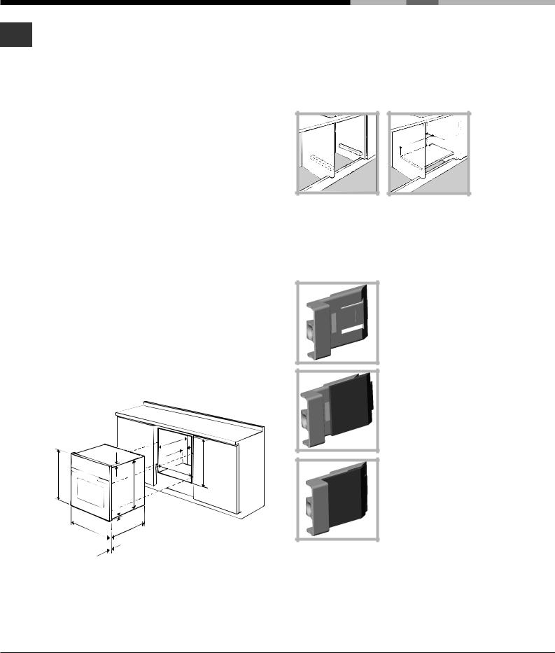
Fitting the appliance
Use the appropriate cabinet to ensure that the appliance functions properly.
•The panels adjacent to the oven must be made of heat-resistant material.
•Cabinets with a veneer exterior must be assembled with glues which can withstand temperatures of up to 100°C.
•To install the oven under the counter (see diagram) and in a kitchen unit, the cabinet must have the following dimensions:
|
|
|
. |
|
23 mm. |
|
.min |
mm.595 |
mm.567 |
mm |
|
585-575mm. |
|||
|
|
|
547 |
|
|
|
. |
|
|
|
mm |
|
|
|
45 |
|
|
560 |
mm. |
|
|
|
|
595 |
|
5 mm. |
|
mm. |
. |
|
|
|
mm |
|
|
|
|
545 |
|
|
. |
|
|
|
mm |
|
|
24 |
|
|
|
! The appliance must not come into contact with electrical parts once it has been installed.
The consumption indications on the data plate have been calculated for this type of installation.
Ventilation
To ensure good ventilation, the back panel of the cabinet must be removed. It is advisable to install the oven so that it rests on two strips of wood, or on a completely flat surface with an opening of at least 45 x 560 mm (see diagrams).
. |
45 |
mm |
. |
mm |
|
||
560 |
|
|
|
Centring and fastening
Position the 4 tabs on the side of the oven according to the 4 holes of the outer frame. Adjust the tabs according to the thickness of the cabinet side panel, as shown below:
thickness of 20 mm: take off the removable part of the tab (see diagram)
thickness of 18 mm: use the first groove, which has already been set in the factory (see diagram)
thickness of 16 mm: use the second groove (see diagram)
Secure the appliance to the cabinet by opening the oven door and putting 4 screws into the 4 holes of the outer frame.
! All parts which ensure the safe operation of the appliance must not be removable without the aid of a tool.
PLEASE PHONE US TO REGISTER YOUR APPLIANCE AND ACTIVATE YOUR PARTS GUARANTEE ON 08448 24 24 24
2

Electrical Connection
Electrical connection
The electrical connection to the mains must be made on the appliance. The power voltage and frequency are as indicated on the rating plate.
! THIS APPLIANCE MUST BE EARTHED.
Fitting the power supply cable
L |
N
1.Open the terminal board by inserting a screwdriver into the side tabs of the cover. Use the screwdriver as a lever by pushing it down to open the cover (see diagram).
2.Install the power supply cable by loosening the cable clamp screw and the three wire contact
screws L-N- . Connect the wires to the corresponding terminals: the Blue wire to the terminal marked (N), the Brown wire to the terminal marked (L) and the Yellow/Green wire to the terminal
marked  (see diagram).
3.Secure the cable by fastening the clamp screw.
4.Close the cover of the terminal board.
Electrical Connection:
Voltage Frequency: 230 V-1+N 50Hz
Fuse Section: 16A
Supply cable: 3x1.5mm2
You can connect your oven to the system means of a terminal board. Refer to above information for the minimal cable sections and the calibration of the protective elements according to the connection.
If the appliance is installed with a junction box, an omnipolar circuit breaker - with a minimum contact opening of 3mm - should be installed between the appliance and the mains.
Power cable supply connection to the electrical mains:
GB
We recommend you use a power supply cable which is long enough to allow you to take the oven out of its recess in the event of maintenance operations (only use HAR - H 05 - RRF quality cables fitted with a plug conforming to the regulations in force.
The plug must be accessible at all times.
Unplug the appliance before all operations, even when replacing the oven lamp.
Using the appliance without correct earthing is highly dangerous.
! After connecting the appliance to the flexible cable, tighten all the screws on the terminal board.

 DATA PLATE
Dimensions |
width cm 43.5 |
|
height cm 32 |
||
|
depth cm 41.5 |
|
Volume |
lt. 58 |
|
Electrical |
voltage: 230-240V ~ 50/60 Hz or |
|
50Hz (see data plate) |
||
connections |
maximum power absorbed |
|
|
2250-2400W |
|
|
Directive 2002/40/EC on the label |
|
|
of electric ovens. |
|
|
Standard EN 50304 |
|
|
Energy consumption for Natural |
|
ENERGY LABEL |
convection – heating mode: a |
|
Convection mode |
||
|
||
|
Declared energy consumption for |
|
|
Forced convection Class – heating |
|
|
mode: bMulti-cooking |
|
|
This appliance conforms to the |
|
|
following European Economic |
|
|
Community directives: |
|
|
- 2006/95/EEC of 12/12/06 (Low |
|
|
Voltage) and subsequent |
|
|
amendments; |
|
|
-2004/108/EEC of 15/12/04 |
|
|
(Electromagnetic Compatibility) and |
|
|
subsequent amendments; |
|
|
- 93/68/EEC of 22/07/93 and |
|
|
subsequent amendments. |
|
|
- 2002/96/EC and subsequent |
|
|
amendments. |
PLEASE PHONE US TO REGISTER YOUR APPLIANCE AND ACTIVATE YOUR PARTS GUARANTEE ON 08448 24 24 24
3
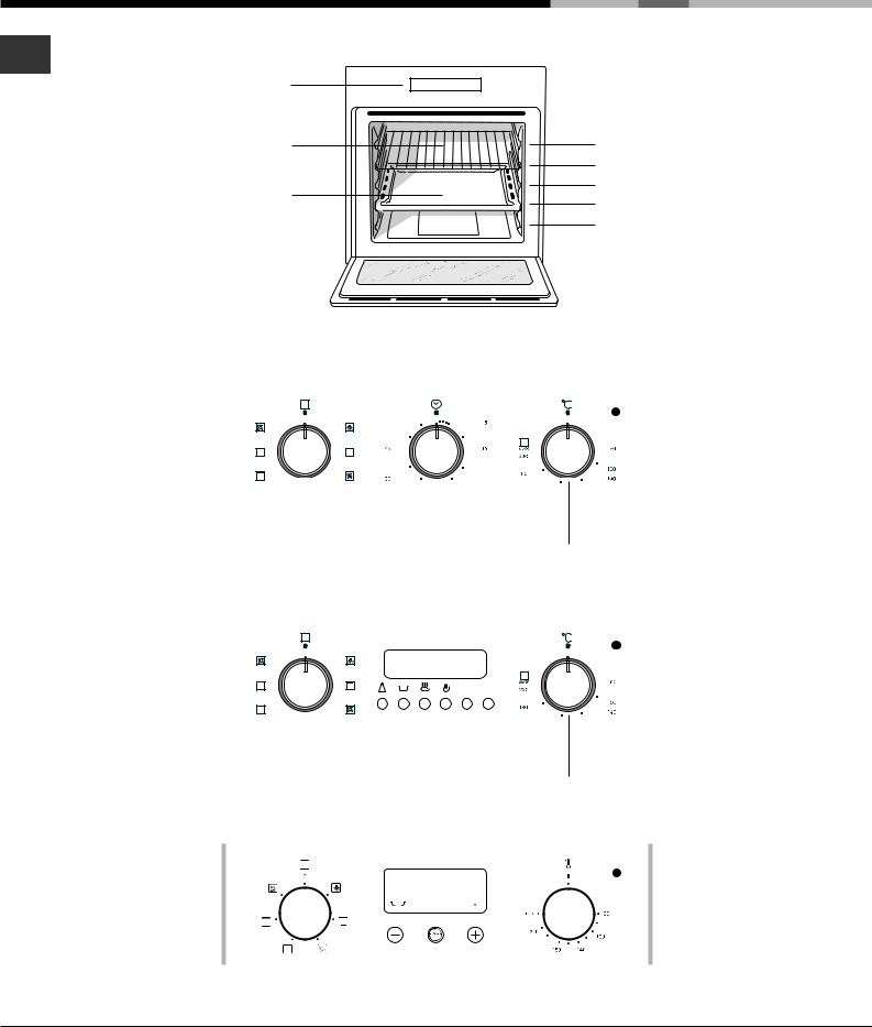
Description of the appliance
Overall view
GB
Control panel |
GUIDES for the |
|
|
sliding racks |
|
GRILL |
position 5 |
|
|
position 4 |
|
DRIPPING PAN |
position 3 |
|
position 2 |
||
|
||
|
position 1 |
Control panel
|
|
|
|
|
|
|
SELECTOR |
|
TIMER |
|
Indicator light |
|||||||||||||||||||
|
|
|
||||||||||||||||||||||||||||
|
|
|
|
|
|
|
Knob |
|
knob* |
|
THERMOSTAT |
|||||||||||||||||||
|
|
|
|
|
|
|
|
|
|
|
|
|
|
|
|
|
|
|
|
|
|
|
|
|
|
|
|
|
|
|
|
|
|
|
|
|
|
|
|
|
|
|
|
|
|
|
|
|
|
|
|
|
|
|
|
|
|
|
|
|
|
|
|
|
|
|
|
|
|
|
|
|
|
|
|
|
|
|
|
|
|
|
|
|
|
|
|
|
|
|
|
|
|
|
|
|
|
|
|
|
|
|
|
|
|
|
|
|
|
|
|
|
|
|
|
|
|
|
|
|
|
|
|
|
|
|
|
|
|
|
|
|
|
|
|
|
|
|
|
|
|
|
|
|
|
|
|
|
|
|
|
|
|
|
|
|
|
|
|
|
|
|
|
|
|
|
|
|
|
|
|
|
|
|
|
|
|
|
|
|
|
|
|
|
|
|
|
|
|
|
|
|
|
|
|
|
|
|
|
|
|
|
|
|
|
|
|
|
|
|
|
|
|
|
|
|
|
|
|
|
|
|
|
|
|
|
|
|
|
|
|
|
|
|
|
|
|
|
|
|
|
|
|
|
|
|
|
|
|
|
|
|
|
|
|
|
|
|
|
|
|
|
|
|
|
|
|
|
|
|
|
|
|
|
|
|
|
|
|
|
|
|
|
|
|
|
|
|
|
|
|
|
|
|
|
|
|
|
|
|
|
|
|
|
|
|
|
|
|
|
|
|
|
|
|
|
|
|
|
|
|
|
|
|
|
|
|
|
|
|
|
|
|
|
|
|
|
|
|
|
|
|
|
|
|
|
|
|
|
|
|
|
|
|
|
|
|
|
|
|
|
|
|
|
|
|
|
|
|
|
|
|
|
|
|
|
|
|
|
|
|
|
|
|
|
|
|
|
|
|
|
|
|
|
|
|
|
|
|
|
|
|
|
|
|
|
|
|
|
|
|
|
|
|
|
|
|
|
|
|
|
|
|
|
|
|
|
|
|
|
|
|
|
THERMOSTAT
Knob
|
|
|
|
|
|
SELECTOR |
|
ELECTRONIC |
|
Indicator light |
|||||||||||||||||||||
|
|
|
|||||||||||||||||||||||||||||
|
|
|
|
|
|
Knob |
|
programmer* |
|
THERMOSTAT |
|||||||||||||||||||||
|
|
|
|
|
|
|
|
|
|
|
|
|
|
|
|
|
|
|
|
|
|
|
|
|
|
|
|
|
|
|
|
|
|
|
|
|
|
|
|
|
|
|
|
|
|
|
|
|
|
|
|
|
|
|
|
|
|
|
|
|
|
|
|
|
|
|
|
|
|
|
|
|
|
|
|
|
|
|
|
|
|
|
|
|
|
|
|
|
|
|
|
|
|
|
|
|
|
|
|
|
|
|
|
|
|
|
|
|
|
|
|
|
|
|
|
|
|
|
|
|
|
|
|
|
|
|
|
|
|
|
|
|
|
|
|
|
|
|
|
|
|
|
|
|
|
|
|
|
|
|
|
|
|
|
|
|
|
|
|
|
|
|
|
|
|
|
|
|
|
|
|
|
|
|
|
|
|
|
|
|
|
|
|
|
|
|
|
|
|
|
|
|
|
|
|
|
|
|
|
|
|
|
|
|
|
|
|
|
|
|
|
|
|
|
|
|
|
|
|
|
|
|
|
|
|
|
|
|
|
|
|
|
|
|
|
|
|
|
|
|
|
|
|
|
|
|
|
|
|
|
|
|
|
|
|
|
|
|
|
|
|
|
|
|
|
|
|
|
|
|
|
|
|
|
|
|
|
|
|
|
|
|
|
|
|
|
|
|
|
|
|
|
|
|
|
|
|
|
|
|
|
|
|
|
|
|
|
|
|
|
|
|
|
|
|
|
|
|
|
|
|
|
|
|
|
|
|
|
|
|
|
|
|
|
|
|
|
|
|
|
|
|
|
|
|
|
|
|
|
|
|
|
|
|
|
|
|
|
|
|
|
|
|
|
|
|
|
|
|
|
|
|
|
|
|
|
|
|
|
|
|
|
|
|
|
|
|
|
THERMOSTAT |
|||
|
|
|
|
|
Knob |
|||
|
|
SELECTOR |
|
ELECTRONIC |
|
|
Indicator light |
|
|
|
|
||||||
|
|
Knob |
|
programmer* |
|
|
THERMOSTAT |
|
|
|
|
|
|
|
|
|
|
|
|
|
|
|
|
|
|
|
 ••
•• ••
••
|
|
|
|
* Only on certain models. |
THERMOSTAT |
||
Knob |
|||
PLEASE PHONE US TO REGISTER YOUR APPLIANCE AND ACTIVATE YOUR PARTS GUARANTEE ON 08448 24 24 24
4

Start-up and use
! The first time you use your appliance, heat the empty oven with its door closed at its maximum temperature for at least an hour. Ensure that the room is well ventilated before switching the oven off and opening the oven door. The appliance may produce a slightly unpleasant odour caused by the burning away of protective substances used during the manufacturing process.
Starting the oven
1.Select the desired cooking mode by turning the SELECTOR knob.
2.Select the desired temperature with the THERMOSTAT knob. See the Cooking advice table for cooking modes and the suggested cooking temperatures (see Cooking Modes).
3.When lit, the THERMOSTAT indicator light indicates that the oven is heating up to the temperature set.
4.You may do the following during cooking:
-change the cooking mode by turning the SELECTOR knob.
-change the temperature by turning the THERMOSTAT knob.
-stop cooking by turning the SELECTOR knob to the “0” position.
!Never put objects directly on the oven bottom to avoid damaging the enamel coating.
!Always place cookware on the rack(s) provided.
Cooling ventilation
In order to cool down the external temperature of the oven, some models are fitted with a cooling fan that blows out air between the control panel and the oven door.
! Once the cooking has been completed, the cooling fan remains on until the oven has cooled down sufficiently.
Oven light
GB
It goes on when selecting with the SELECTOR knob. It stays on when a cooking mode is selected.
How to use the timer*
1.To set the buzzer, turn the TIMER knob clockwise almost one complete revolution.
2.Turn the knob anticlockwise to set the desired time: align the minutes shown on the TIMER knob with the indicator on the control panel.
3.The timer operates in minutes: when the selected time has elapsed, a buzzer will sound.
! The timer does not turn the oven on or off.
* Only on certain models
PLEASE PHONE US TO REGISTER YOUR APPLIANCE AND ACTIVATE YOUR PARTS GUARANTEE ON 08448 24 24 24
5
 Loading...