

Page 1
Honeywell
XYR301X quick install guide
XYR301X-Series Quick setup guide
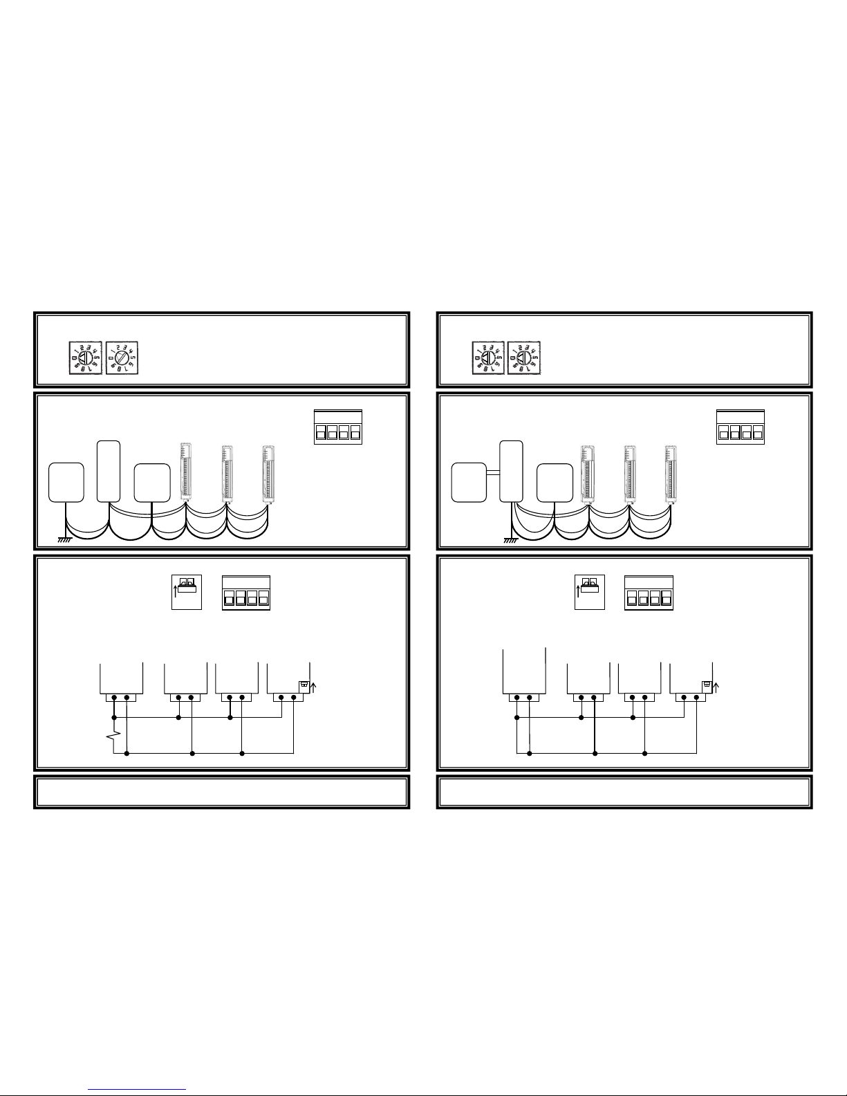
Modbus
master
XYR30
XYR30
Set a unique Modbus slave address for each
XYR301X connected to the Modbus master.
Example here address = 01.
Master
power
supply
Connect power:
(10.8-15.6 VDC) to ‘+’
and EARTH to ‘-‘.
XYR3011: 300mA max
XYR3012: 900mA max
XYR3013: 900mA max
B A - +
POWER
ADDRESSING
x10
x1
ON
B A - +
A, B: Connect RS485
(Modbus)
RS485
termination
switch.
Up = terminate
Down = unterminated
Power and
Modbus
connector
RS485
Modbus
master
XYR
301X
XYR
301X
XYR
301X
A B A B A B A B
Termination
switch up
(terminated)
120
Ω
ø
2mm EARTH wire
XYR301X
power
supply
12VDC
power
power
power
power
modbus
modbus
modbus
earth
Connection to a Modbus master
Consult user manual for Modbus addresses.
XYR 3000
radio
Address switches must be 00 for XYR3000 protocol.
Master
power
supply
Connect power:
(10.8-15.6 VDC) to ‘+’
and EARTH to ‘-‘.
XYR3011:
300mA max
XYR3012
: 900mA max
XYR3013
: 900mA max
B A - +
POWER
ADDRESSING
x10
x1
ON
B A - +
A, B: Connect RS485
RS485
termination
switch.
Up = terminate
Down = unterminated
Power and
RS485
connector
RS485
XYR 3000
radio
(RS485-
terminated)
XYR
301X
XYR
301X
XYR
301X
A B A B A B A B
Termination
switch up
(terminated)
ø
2mm EARTH wire
Battery
12VDC
power
power
power
RS485
RS485
RS485
earth
Connection to XYR3000 Radio
Set up using Wireless IO and Gateway Configuration Utility.
power
sup
bat
XYR301
XYR301X
XYR301X
XYR301X
Page 2

Honeywell
XYR301X quick install guide
XYR301X-Series Quick setup guide -
Wiring
Voltage-free contact
Transistor
switch
device
V+
V+
V-
DIO1
DIO2
EARTH
XYR301X
_
DC
Load
Max 30VDC
200mA
DIO1
DIO2
EARTH
XYR301X
V-
AIN3
AIN4
AGND
XYR3012
ALS +24V
Externally
powered
sensor
-
AIN1
AIN2
Loop powered
sensor
Power
supply
V-
AIN1
AIN2
AGND
ALS +24V
Loop powered
sensor
Exter
nally
powered
sensor
-
V-
AIN3
AIN4
AGND
XYR3012
ALS +24V
Sensors with
voltage signals
AIN1
AIN2
-
AIN1
AIN2
AGND
XYR3012
ALS +24V
Sensor with
voltage signal
XYR3011
XYR3012
DIGITAL INPUTS
DIGITAL OUTPUTS
DIFFER
ENTIAL
CURRENT INPUTS
(Select using config software)
SINGLE
-
ENDED
CURRENT INPUTS
(Default configuration)
DIFFERENTIAL
VOLTAGE INPUTS
(Select using config software)
SINGLE
-
ENDED
VOLTAGE INPUTS
(Select using config software)
XYR3013
AOT1
AOT2
AGND
XYR3013
ALS +24V
PLC
COM
CURRENT
SOURCE OUTPUT
(Default configuration)
V-
AOT1
AOT2
AGND
XYR3013
ALS +24V
PLC
AI+
AI-
+
CURRENT SINK
OUTPUT
(Select using config software)
V-
AOT1
AOT2
AGND
XYR3013
ALS +24V
PLC
VOLTAGE
INPUT
AI
COM
VOLTAGE OUTPUT
(Select using config software)
 Loading...