

Page 1

Quick Start Guide
Honeywell XYR 300L Wireless
I/O Transmitter Unit
man_XYR_300L_QuickStart_v1-8.doc
Page 2
Honeywell XYR 300L Wireless I/O Transmitter Unit Quick Start Guide
About this document
This document is the Honeywell XYR 300L Wireless I/O Transmitter Unit Quick Start Guide
and contains the following sections:
Section Read this section if you want to …
Basic steps for using your unit Learn the basic steps for installing and using your unit.
Unit components Understand the different parts of your unit.
Antenna installation Learn how to install an antenna with your unit.
Resetting factory defaults Reset your unit to the original factory default settings.
Safety information Understand important safety information related to your unit.
NOTE: You must read this information before installing your unit.
Specifications Know technical information about your unit.
For more information, see the next sections.
Basic steps for using your unit
This document describes how to configure your unit using the default factory configuration that
lets you easily setup your network as a simple send/receive network using a dedicated pair of
transmitter and receiver units.
The basic steps for using your unit are:
1. Configure your network using the XYR 300 configuration utility. For more information
on setting a user-defined customised configuration, see the XYR 300L User Manual.
2. Bench test your configuration before deploying.
3. Connect the antenna, power supply and transducer signals using the instructions in
this document. Power supply and transducer connection is described in the section.
Antenna connection is described in the section Antenna installation. For more
information, see the XYR 300L Installation Manual.
Honeywell XYR 300L Wireless I/O Transmitter Unit Version 1.8 page 2 of 8
Page 3
Honeywell XYR 300L Wireless I/O Transmitter Unit Quick Start Guide
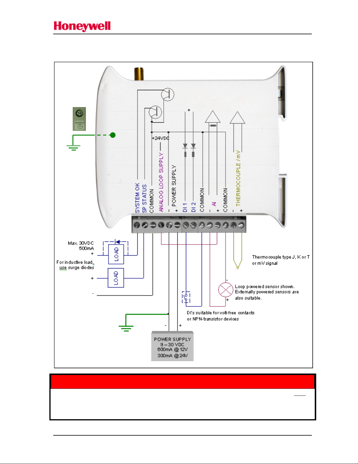
Unit components and connections
Your XYR 300L transmitter unit has the following components and terminal connections:
Earth Wire Lug
underneath Unit
In order to comply with Electrical Safety Regulations, this module must be installed in an Electrical AND
Fire enclosure. This enclosure may be a single or multiple enclosures. Access to the module is to be
made by a Service Person only.
**IMPORTANT ELECTRICAL SAFETY INFORMATION**
Honeywell XYR 300L Wireless I/O Transmitter Unit Version 1.8 page 3 of 8
Page 4

Honeywell XYR 300L Wireless I/O Transmitter Unit Quick Start Guide
The front panel contains the following components:
SMA antenna connector
At top of unit
RS232 configuration
port
Rotary switch for set-point
settings
The triangle on the rotary switch indicates the current position, for example:
Set Point
NOTE: To avoid damaging the rotary switch, use a screwdriver to change the position.
The LEDs on the front panel indicate the unit status:
LED Status Indicates
None No power supply.
OK LED Green Current status of the unit OK.
OK LED Red Fault condition detected in unit.
TX Led Flashes Transmitting Message.
PG LED on Configuration Cable Connected.
Input LED ON Input LEDS (i.e. D1,D2, SP, AZ.) light when the corresponding input is active.
D1 Digital Input 1 is active (Low).
D2 Digital Input 2 is active.
SP Analog Setpoint is active.
AZ Analog Input is zero mA
All LEDs medium flash Medium speed flash (1.6HZ) indicates the module is half-way through the
configuration process. Medium flash also happens when you set the rotary switch to
position 0 when powering on the unit.
Honeywell XYR 300L Wireless I/O Transmitter Unit Version 1.8 page 4 of 8
Page 5

Honeywell XYR 300L Wireless I/O Transmitter Unit Quick Start Guide
XYR 300L
Antenna installation
Honeywell XYR 300L Wireless I/O Transmitter Unit Version 1.8 page 5 of 8
Page 6

Honeywell XYR 300L Wireless I/O Transmitter Unit Quick Start Guide
Safety information
Thank you for selecting the XYR 300L transmitter for your telemetry needs. We trust it will give you many years of
valuable service. To ensure your 905U-L transmitter enjoys a long life, double-check ALL your connections with the
user’s manual before powering on the unit.
WARNING: Incorrect termination of supply wires may cause internal damage and will void warranty.
Exposure to RF energy is an important safety consideration. The FCC has adopted a safety standard for human
exposure to radio frequency electromagnetic energy emitted by FCC regulated equipment as a result of its actions in
Docket 93-62 and OET Bulletin 65 Edition 97-01.
FCC Notice when used in USA: XYR 300L Wireless I/O Module
Part Additional information
15 This device has been tested and found to comply with the limits for a Class B digital device, pursuant to
Part15 of the FCC rules (Code of Federal Regulations 47CFR Part 15). Operation is subject to the condition
that this device does not cause harmful interference.
This device complies with Part 15.247 of the FCC Rules. Operation is subject to the following two conditions:
This device may not cause harmful interference; and
This device must accept any interference received, including interference that may cause undesired operation
Industry Canada: XYR 300L Wireless I/O Module
RSS-119 - This device has been type accepted for operation by Industry Canada in accordance with RSS-119 of the
Industry Canada rules. See the label on the unit for the specific Industry Canada certification number and any other
certification designations.
NOTE: Any changes or modifications not expressly approved could void the user’s authority to operate this
equipment.
Safety information
NOTE: This equipment is suitable for use in Class 1 Division 2 groups A, B and C or non-hazardous locations only.
Unit specifications
Input/output Number Additional information
Digital inputs 2
Analog inputs 1
Thermocouple inputs 1
Power supply 1
Transmitter 1
Frequency 902-928 MHz
Dry-contact digital inputs slow-pulsed at 10Hz.
All inputs are suitable for voltage free contacts (e.g. mechanical
switches) or NPN transistor devices (e.g. electronic proximity
switches).
NOTE: PNP transistor device inputs are NOT suitable.
0-20mA differential input; 16-bit resolution, 0.1% accuracy, 10 ohm
input impedance.
J, K or T type thermocouple with on-board cold-junction
compensation.
Cold junction compensation accuracy ±1º over ambient temp range: 40º to +70ºC.
9-30 VDC 1 Amp CSA certified Class 2 power supply. For use in
Class 1 Div 2 explosive areas, the power supply must be approved for
Class 1 Div 2 use.
WARNING: Explosion hazard - do not disconnect while circuit is live
unless area is known to be non-hazardous.
1 Watt Frequency Hopping Spread Spectrum (FHSS) Transmitter.
Actual frequency range depends on country.
Honeywell XYR 300L Wireless I/O Transmitter Unit Version 1.8 page 6 of 8
Page 7

Honeywell XYR 300L Wireless I/O Transmitter Unit Quick Start Guide
Document information
Quick Start Guide Honeywell XYR 300L Wireless I/O Transmitter Unit Version 1.7
This page is intentionally blank.
Honeywell XYR 300L Wireless I/O Transmitter Unit Version 1.8 page 7 of 8
Page 8

Honeywell XYR 300L Wireless I/O Transmitter Unit Quick Start Guide
This page is intentionally blank.
Honeywell XYR 300L Wireless I/O Transmitter Unit Version 1.8 page 8 of 8
 Loading...