

Page 1
UDC2300
51-52-03-27
8/99
Page 1 of 12
Universal Digital Controller
Overview
The UDC 2300 Universal Digital
Controller is a new low priced
addition to Honeywell’s LeaderLine
family.
This controller introduces new
features in the popular low priced
¼ DIN size while retaining all the
reliability, cost effectiveness,
simplicity, and popular HMI of
Honeywell’s UDC 2000.
The UDC 2300 monitors and controls
temperatures and other variables in
applications such as environmental
chambers, plastic processing
machines, furnaces and ovens, and
packaging machinery. The standard
features include AccutuneII™ and the
popular single display, automatic
mode model. A Dual Display model
with Automatic/Manual control modes
is optional. A Limit Control model is
also available.
The UDC 2300 provides a low priced,
1/4 DIN sized alternative for many
applications. Its new features
include:
Universal AC power supply,
RS485 ASCII or Modbus RTU
communications option,
Input/Output isolation, and
Isolated Auxiliary Current
output.
These features when combined with
the new AccutuneII tuning with
Fuzzy Logic overshoot suppression,
result in price/performance
leadership in the performance
segment positioned below the
UDC 3300 Controller.
For the many thousands of satisfied
UDC 2000 users, UDC 2300 is
downward compatible with existing
UDC 2000 applications and
installations. It even uses the same
case; therefore, it can be easily
inserted into existing panel
installations.
Modbus is a trademark of AEG Modicon
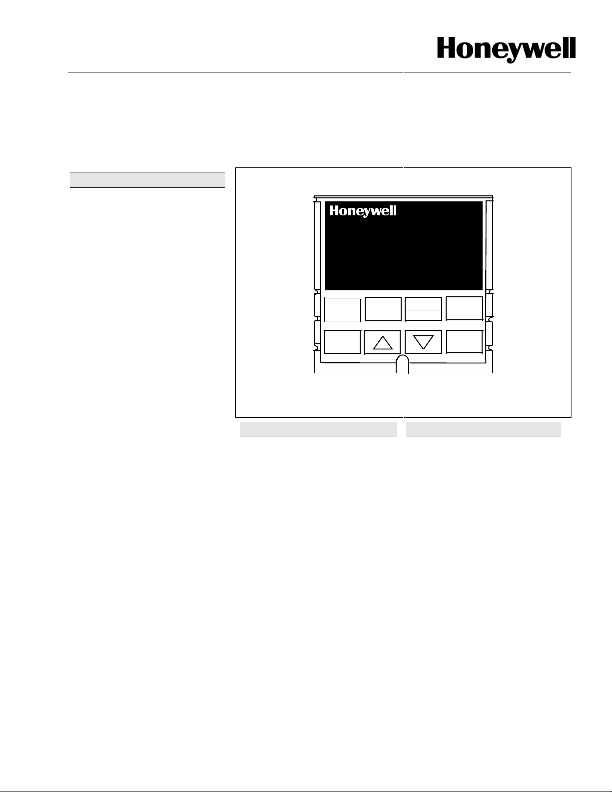
Figure 1—UDC 2300 Controller has a sealed faceplate suitable for
hosedown applications
Features/Options
High Accuracy
full scale input with a typical resolution
of 15 bits.
Analog Inputs
available. The first input accepts all
thermocouple, RTD, mA, mV, and
voltage types (See Table 1.).
Alternatively, the second input is a
high level input and can be used as a
remote setpoint, for data acquisition, a
parameter to be alarmed on. All input
types are configurable. All inputs are
sampled six times per second (every
166 ms). These two inputs are
isolated from all other inputs and
outputs, but not from each other.
Dual Setpoints -
selection allows quick switchover from
primary to alternate setpoint with
minimal operator confusion.
Manual/Automatic Modes
Bumpless, balanceless transfer
between control modes. Available with
a Dual Display option and SP
Programming option.
—Two inputs are
ALM
1
2
1
OUT
2
SP 2300
FUNCTION
AUTO
TUNE
—Typically ±0.25% of
Simple push-button
DISPLAY
—
Specification
2300
MAN-AUTO
RESET
Features/Options, continued
Accutune II™
provides a new, truly plug and play
tuning algorithm, which will, at the
touch of a button or through a digital
input, accurately identify and tune any
process including those with
deadtime and integrating processes.
This speeds up and simplifies start-up
plus allows retuning at any setpoint.
Fuzzy Logic
uses fuzzy log ic to suppress process
variable overshoot due to SP
changes or externally induced
process disturbances. It operates
independently from AccutuneII
tuning. It does not change the PID
constants, but temporarily modifies
the internal controller response to
suppress overshoot. This allows more
aggressive tuning to co-exist with
smooth PV response. It can be
enabled or disabled depending on the
application or the control criteria.
CE
Low Voltage Directive and
89/336/EEC, the EMC Directive as a
standard feature.
PV
F
C
M
A
R
L
SET UP
RUN
HOLD
—This standard feature
—This standard feature
Mark
—Conformity with 73/23/EEC,
Industrial Automation and Control, 1110 Virgini a Dri ve, Fort Washington, PA 19034
Printed in U.S.A. ■ © Copyright 1999—Honeywell Inc.
Page 2

51-52-03-27
Page 2
Features/Options, continued
Auxiliary Output* (Optional)
isolated Auxiliary Output can be
scaled from 4-20 mA for 0 to 100%
for any range. It can be configured to
represent Input 1, Input 2, PV, active
Setpoint, Local SP1, Deviation, or
the Control Output..
Communications* (Optional)
Provides a communications link
between the UDC 2300 and host
computer or PLC via the RS422/485
ASCII or Modbus® RTU
communications option.
Digital Input* (Optional)
isolated digital input for remote dry
contact closure to select one of the
following actions:
• Manual control mode
• Local setpoint 1
• Local setpoint 2
• Direct controller action
• Hold SP Ramp/Programming
• Select PID set 2
• To Run - SP Ramp/Program
• External program reset
• Disable PID integral action
• Manual mode, failsafe output
• Disable keyboard
• Start Timer
• Initiate Tuning
• Initiate PV Hot Start
• Output tracks Input 2
• To Remote Setpoint
• To Latching Manual Mode
Also the digital input can allow
one of the following selections to
be combined with one of the
above selections:
• Select PID set 2
• Direct controller action
• Local setpoint 2
• Local setpoint 1
• To Run
New Alarm Function Features
• Alarms can be configured as
latching or non-latching.
• Alarm blocking is also available
which allows start-up without alarm
energized until after it first reaches
the operating region.
• PV rate of change alarm
• Loop break alarm
• Timer output reset
Universal Switching Power
Operates on any line voltage from 90
to 264 Vac 50/60 Hz without
jumpers. 24 Vac/dc instrument power
is available as an option.
*Auxiliary Output, Digital Input, and
Communications are mutually exclusive.
—This
—
—Provides
—
Features/Options, continued
Moisture Protection
rated front face permits use in
applications where it may be
subjected to moisture, dust, or hosedown conditions.
Limit Control
relay , which is activated whenever
the PV goes above or below a preset
setpoint value. An alarm indicator will
light when the output is activated.
Reset is through a key on the front of
the controller or an external switch. A
FM approved model is available.
—Provides a latching
Approval Body Options
approval and CSA certification are
available options. A UL listing applies
to regulatory use only and is a
standard feature.
Timer
—This standard feature
provides a configurable time period of
0 to 99 hours, 59 minutes or units of
minutes and seconds. It can be
started via the keyboard, alarm 2, or
by a digital input. The timer output is
Alarm 1 which energizes at the end of
the Timer Period. Alarm 1 can be
automatically reset. The Timer Period
can be changed between each batch.
Status is shown on the lower display.
Heat/Cool Capability
range control with independent PID
tuning constants—one for heating,
one for cooling—plus mixed output
forms.
Setpoint Ramp/Soak Programming
(Optional)
and store six Ramp and six Soak
segments for setpoint programming.
Run or Hold of program is keyboard or
remote digital switch selectable.
—Enables you to program
Setpoint Rate
ramp rate to be applied to any local
setpoint change. A separate upscale
or downscale rate is configurable. A
single setpoint ramp is also available
as an alternative.
Thermocouple Failsafe
Configurable upscale or downscale
burnout and failsafe output level.
Decimal Point Location
Configurable for none, one, or two
places.
Indicator Model
indicator model is available. Optional
features include: 2 alarms plus
Auxiliary Output or Communications.
—IP65/NEMA 3
—FM
—Provides split
—Lets you define a
—
—
—A single display
Features/Options, continued
Dedicated Keys
access setpoint modes and setpoint
program status to simplify and speed
operation.
Two Sets of Tuning Constants
Two sets of PID parameters can be
configured for each loop and
automatically or keyboard selected.
Alarm Selection
relays to activate external equipment
when preset high/low setpoints are
reached. There is an indicator for
each alarm. For Duplex or 3 Position
Step operation, only one alarm is
available.
Data Security
board security protect tuning,
configuration, and calibration data,
accessed by a configurable 4-digit
code. Nonvolatile EEPROM memory
assures data integrity during loss of
power.
Diagnostic/Failsafe Outputs -
Continuous diagnostic routines detect
failure modes, trigger a failsafe output
value and identify the failure to
minimize troubleshooting time.
High Noise Immunity -
controller is designed to provide
reliable, error- free performance in
industrial environments that often
affect highly noise-sensitive digital
equipment.
Quality/Support
covered by a 2-year warranty and
backed up by a toll-free phone
number for technical assistance.
Transmitter Power
30 volts dc to power a 2-wire
transmitter. (Requires use of alarm 2
open collector output selection or
auxiliary output.).
—Provide direct
—
—None, one, or two
—Five levels of key-
The
—The UDC 2300 is
—Provides up to
Physical Description
The controller is housed in a 4.2-inch
deep, black metal case with a dark
gray elastomer bezel, that can be
panel mounted in a 1/4 DIN cutout.
(See Figure 5.) The plug-in chassis
allows easy access to the controller
board and its various option boards.
All power, input, and output wiring are
connected to screw terminals on the
rear panel. (See Figure 6.) Blue and
tan elastomer bezels are optionally
available.
Page 3

51-52-03-27
Page 3
Configuration
You decide how the controller is to
interact with the process by
selecting, through simple keystrokes,
the functions you want.
Multi-language prompts guide the
operator step-by-step through
configuration process assuring quick
and accurate entry of all configurable
parameters. Five languages are
available via configuration: English,
French, German, Spanish and
Italian.
the
Inputs
The analog inputs are sampled six
times a second.
The UDC 2300 is available with one
or two inputs. The first input, or
Process Variable input, can be one
of the various thermocouple, RTD,
Radiamatic or linear actuations.
Linear actuations have
thermocouple, RTD, and Radiamatic
transmitter characterization capability
as a standard feature.
The optional second input is a high
level input and accepts ranges of
0-5V, 1-5V, 0-20mA, or 4-20mA.
All actuations and characterizations
are keyboard configurable. Cold
junction compensation is provided for
thermocouple type inputs. Upscale or
downscale sensor break protection is
keyboard configurable. A configurable
digital filter of 0 to 120 seconds
provides input signal damping.
Output Types
The following output types are
available per the model selection
guide:
• Current Output
• Electromechanical Relays (5
amps)
• Solid State Relays (1 amp)
• Solid State Relays (10 amps)
externally mounted (optional)
• Open Collector Outputs
• Auxiliary Current Output (optional)
Output Algorithms
The UDC 2300 is available with one
or more of the following output
algorithms:
Time Proportional—Provides On-Off
or Time Proportional (Relay) output.
Current Proportional—Supplies
proportional direct current output for
final control elements which require a
4-20 mA signal.
Current Proportional Duplex—
Similar to current proportional but
provides a second set of tuning
parameters and a split range current
output or a second current output via
the Auxiliary output option, for the
heat and cool zones.
Time Proportional Duplex—
Depending on which control algorithm
you select, this duplex output
algorithm can provide On-Off Duplex,
Time Proportional Duplex, or Three
Position Step Control. The time
proportional duplex output provides
independent PID tuning constants and
two time proportional outputs; one for
heat zone above the 50% output, and
one for cool zone below 50% output.
Current/Relay Duplex (Relay =
Heat)—A variation of Duplex with
Current active for 0 to 50% output
(PID Set 2) and Relay 2 active 50
to100% output (PID Set 1). Note that
only one alarm is available.
Relay/Current Duplex (Relay =
Cool)—A variation of Duplex with
Current active for 50 to 100% output
and Relay 2 is active for 0 to 50%
output. Not that only one alarm is
available.
Universal Output Model—Flexibility
of the output algorithms allows the
current output with two alarms model
(DC230B-CE) to also be configured
for current simplex, current duplex,
and time simplex. A relay output
model with auxiliary output option
(DC230B-CE-2) can also be
configured for these output
algorithms. Note that only current
simplex and current duplex can have
2 alarms.
Control Algorithms
Depending on the output algorithms
specified, the controller can be
configured for the following control
algorithms:
• On-Off
• PID-A
• PID-B
• PD with Manual Reset
• Three Position Step Control
The Three Position Step Control
algorithm allows the control of a
valve (or other actuator), with an
electric motor driven by two
controller output relays; one to
move the motor upscale, the
other downscale without a
feedback slidewire linked to the
motor shaft.
Control Modes
The controller is capable of operating
in three different control modes:
1. Manual
2. Automatic with Local Setpoint
3. Automatic with Remote Setpoint
The manual and automatic control
modes with local and remote setpoint,
and bumpless, balanceless transfer
between modes.
Alarms
Alarm output terminals are located at
the rear terminal panel. One or two
electromechanical alarm relays are
available to activate external
equipment when preset alarm
setpoints are reached. Each of the
two alarms can be set to monitor two
independent setpoints. Each alarm
setpoint can be either high or low
alarm. The alarm type can be
selected to be either of the inputs,
the Process Variable, Deviation,
Output, Shed from communications,
PV rate of change, or to alarm on
manual mode. It can also be used as
an On or Off event at the beginning
or end of a Ramp/Soak segment.
The alarm hysteresis is configurable
from 0 to 100% of range.
Configurable alarm features include:
•Alarm latching or non-latching
•Alarm blocking
•PV rate of change alarm
•Loop break alarm (Future)
•Timer reset
Page 4
51-52-03-27
Page 4
Upper Display - Four digits
• Normal operation - Process Variable
• Configuration mode - displays parameter
value or selection
ALM - Alarm
conditions exist
OUT - Control
Relay
1 or 2 on
-
Keys
See
Figure 3
ALM
1
1
OUT
FUNCTION
AUTO
TUNE
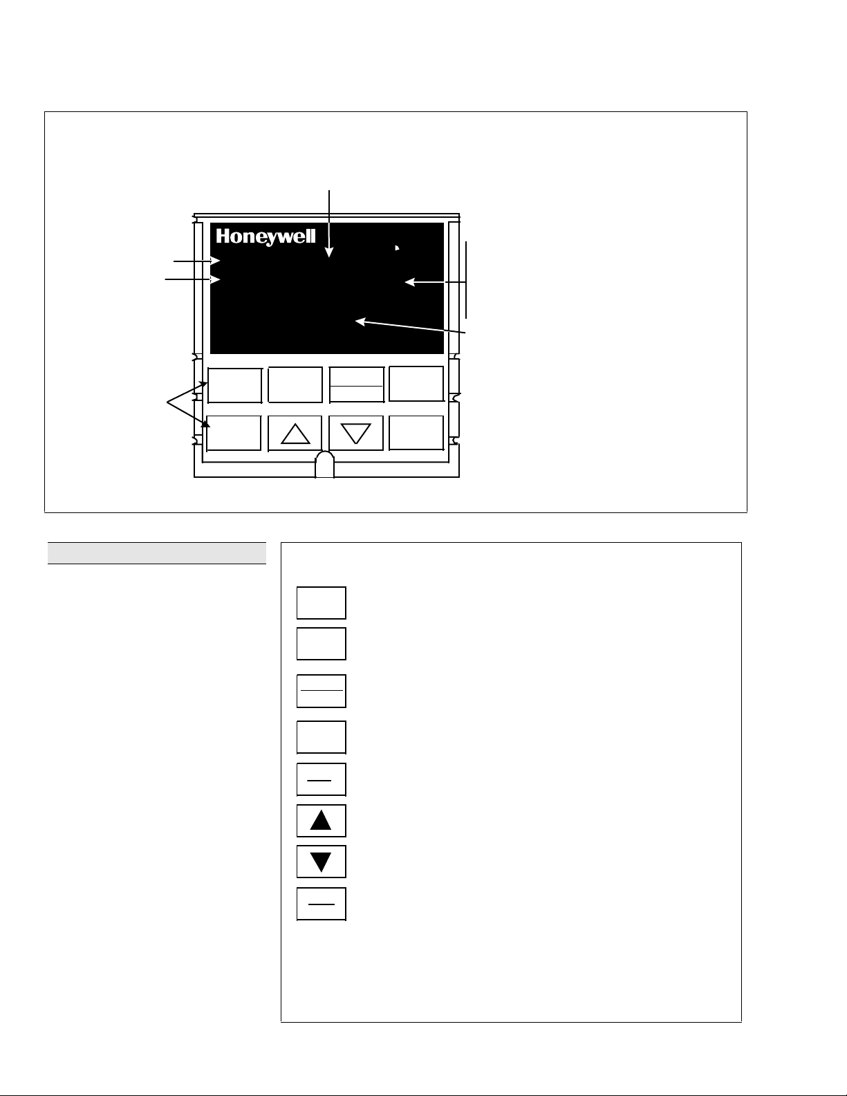
Figure 2—Operator Interface
Operator Interface (Figure 2)
Indicators—Provide alarm, control
mode, and temperature unit indication.
There is also indication of when
Remote Setpoint is active, the status
of the control relays, and whether a
setpoint program is in Run or Hold
mode.
Displays—A 4-digit upper display is
dedicated to the process variable
during normal operation with alternate
information displayed when in the
configure mode. The upper display is
also dedicated to the single display
model operation and also shows
Setpoint output or Deviation on
demand. The
Indicator
Upper Display only.
During normal operation of the dual
display model, the six character alphanumeric lower display sho ws keyselected operating parameters such
as Output, Setpoints, Inputs,
Deviation, active Tuning Parameter
Set, Timer Status, or minutes
remaining in a setpoint ramp. It also
provides guidance, through language
prompts, for the operator during
controller configuration.
model uses the
2
2
2300
SP 2300
DISPLAY
MAN-AUTO
Eight keys enable complete configuration and operation
FUNCTION
DISPLAY
MAN-AUTO
RESET
SET UP
AUTO
TUNE
RUN
HOLD
Figure 3—Key Functions
F - °Fahrenhei t being used
C - °Centigrade being used
M or A - Manual/Auto display
- Remote or Local SP2 setpoint active
R
L - Local setpoint active
Lower Display - Six alpha-numeric characters
• Normal operation - displays operating
parameters and values (four numeric digits)
• Configuration mode - displays functions
and parameters
RESET
F
C
M
A
R
L
SET UP
HOLD
PV
RUN
Selects functions withi n each configuration group.
Selects 2nd Setpoint or Remote Setpoint.
Returns Controller to normal display from Set Up mode.
Toggles various operating parameters for display.
Selects Manual or Auto mode .
Resets the latching Limit Controller relay.
In Set Up mode, used to restore original value or s election.
Scrolls through the configuration groups.
Initiates Limit Cycle Tuning.
Increases setpoint or output value. Increases the
configuration val ues or changes functions in Conf iguration mode groups.
Decreases setpoint or output value. Decreases the
configuration val ues or changes functions in Conf iguration mode groups.
Enables Run/Hold of the SP Ramp or Program
plus Timer sta rt.
22350.ppt
Page 5

51-52-03-27
Page 5
Specifications
Design
CE Conformity (Europe) This product is in conformity with the protection requirements of the following
Product Classification: Class I: Permanently Connected, Panel Mounted Industrial Control Equipment
Enclosure Rating: Panel Mounted Equipment, IP 00, this controller must be panel mounted.
Installation Category
(Overvoltage Category):
Pollution Degree: Pollution Degree 2: Normally non-conductive pollution with occasional
EMC Classification: Group 1, Class A, ISM Equipment (EN 55011, emissions), Industrial Equipment
Method of EMC Assessment: Technical File (TF)
Declaration of Conformity: 51309871-000
Input Accuracy ± 0.25% of full scale typical (±1 digit for display)
Sampling Rate Inputs sampled six times a second
Temperature Stability ±0.025% of full scale span per °C typical
Input Signal Failure Protection
Input Impedance
Maximum Lead Wire Resistance
Stray Rejection Common Mode
Alarm Outputs One SPDT electromechanical relay.
Controller Output Types Current Output
European Council Directives: 73/23/EEC, the Low Voltage Directive, and
89/336/EEC, the EMC Directive. Conformity of this product with any other “CE
Mark” Directive(s) shall not be assumed.
with protective earthing (grounding). (EN61010-1)
Terminals must be enclosed within the panel. Front panel IP 65 (IEC 529).
Category II: Energy-consuming equipment supplied from the fixed installation.
Local level appliances, and Industrial Control Equipment. (EN 61010-1)
conductivity caused by condensation. (Ref. IEC 664-1)
(EN 50082-2, immunity)
Can be field calibrated to ±0.05% of full scale typical
15-bit resolution typical
Thermocouple Inputs:
Burnout Current:
Failsafe Output Level:
4-20 Milliampere Input:
0-10 Volt Input:
All Other:
10 megohms
Thermocouples:
100, 200, and 500 RTD:
100 Low RTD:
AC (50 or 60 Hz):
ohms. 120db at 240Vac with a maximum source impedance of 40 ohms.
DC:
120 dB (with maximum source impedance of 100 ohms) or a ±1 LSB
whichever is greater with 120 Vdc applied.
DC (to 1 KHz):
LSB whichever is greater with 50 Vac applied.
Normal Mode
AC (50 or 60 Hz):
A second alarm is available using the second control relay. This is not available
with Relay Duplex, Time/Current Duplex, or Three-Position Step control.
Up to four setpoints are independently set as high or low alarm, two for each
relay. Setpoint can be on any Input, Process Variable, Deviation, Manual Mode,
Failsafe, PV Rate, RSP Mode, Communication Shed, or Output. A single
adjustable hysteresis of 0.0 to 100.0% is provided. The alarm can also be set as
an ON or OFF event at the beginning of a setpoint ramp/soak segment.
Upscale or downscale burnout
0.13 microamps
Configurable 0-100%
249 ohms
200K ohms
100 ohms/leg
100 ohms/leg
10 ohms/leg
120 dB at 120Vac with a maximum source impedance of 100
80 dB (with maximum source of impedance of 100 ohms) or ±1
60 dB (with 100% span peak-to-peak maximum)
Alarm Relay Contacts Rating
Resistive Load:
Range can be set anywhere between 0 to 21 mA, and as direct or reverse action.
Resolution:
Accuracy:
Temperature Stability:
Load Resistance:
5 ampere at 120 Vac or 30Vdc, 2.5 ampere at 240Vac
11 bits for 0 to 21 mA
0.5% full scale
0.1% F.S./°C
0 to 750 ohms
Page 6

51-52-03-27
Page 6
Specifications, continued
Design (continued)
Controller Output Types (continued) Electromechanical Relays (One or Two)
Controller Output Algorithms On-Off or Time Proportional
Digital Input (Optional)
(Isolated)
Input Filter
SPDT contacts. Both Normally Open and Normally Closed contacts are brought
out to the rear terminals.
Internally socketed
Resistive Load:
Inductive Load:
Motor:
1/6 H.P.
Solid State Relays (One or Two)
SPST solid state contacts consisting of a triac N.O. output.
Internally socketed
Resistive Load:
Inductive Load:
Minimum Load:
Open Collector Outputs (One or Two)
Maximum Sink Current:
Overload Protection:
Internally powered @ 25 Vdc
Opto-isolated from all other circuits except current output, but not from each
other.
Socketed jumper assembly replaces relay.
Solid State Relays (10 amps)
One or two externally mounted SPST triac N.O. outputs for use with open
collector outputs.
Resistive Load:
Inductive Load:
Motor Rating:
One relay or open collector output. Control action can be set for direct or reverse.
5 amps @ 120 Vac or 30Vdc, 2.5 ampere at 240Vac
50 VA @ 120 Vac or 240 Vac
1.0 amp @ 25°C and 120 or 240 Vac
0.5 amp @ 55°C and 120 or 240 Vac
50 VA @ 120 Vac or 240 Vac
20 milliamps
20 mA
100 mA
15 amps @ 25°C and 120 or 240 Vac
10 amps @ 55°C and 120 or 240 Vac
50 VA @ 120 Vac or 240 Vac
1 HP @ 25°C
0.75 HP @ 55°C
Time Proportional Relay Resolution:
On-Off Duplex, Three Position Step Control, or Time Proportional Duplex
Two relays or open collector outputs. Control action can be set for direct or
reverse.
Time Proportional Relay Duplex Resolution:
Current Proportional
A single 4-20 mA current output signal which can be configured for direct or
reverse action.
Current Proportional Duplex
A single split current output for both heat and cool (4-12 cool, 12-20 heat) or a
combination of current proportional output (Heat = 50 to 100% of range) and
auxiliary current output (Cool = 0 to 50% of range). Both are 4-20 mA signals
which can be set for direct or reverse action.
Current/Time Duplex
Variation of time proportional duplex for Heat/Cool applications. Time proportional
output (heat or cool) is a relay. Current proportional output (Heat or Cool) is a 420 mA signal that can be fed into a negative or positive grounded load of 0 to 750
ohms and is operational over 50% of range or the entire range.
+25 Vdc source for external dry contacts or isolated solid state contacts. The
Digital Input option detects the state of external contact.
On contact closure the controller will respond according to how the digital input is
configured. Opening contact causes return to previous state.
Software
seconds available on both analog inputs.
: Single pole lowpass section with selectable time constants, off to 120
3.3 msec
3.3 msec
Page 7

Specifications, continued
Design (continued)
Auxiliary Linear Output (Optional)
(Isolated)
Communications Interface (Optional)
RS422/485 ASCII
RS422/485 Modbus RTU
Setpoint Ramp/Soak Programming
(Optional)
Digital Displays Vacuum fluorescent, Dual Displays
Indicators Alarm Relay Status (ALM 1 or 2)
Modes of Operation Manual (Available on Dual Display version only.)
Dimensions See Figure 5.
Mounting Panel-mounted, 4.2-inch depth
Wiring Connections Screw terminals on the rear of the case. (See Figure 6.)
Power Consumption 12 VA maximum (90 to 264 Vac) and (24 Vac/dc)
Power Inrush Current
Weight 1 kg (2.2 lbs.)
21 mA dc maximum into a negative or positive grounded load or non-grounded
load of 0 to 500 ohms.
Output range can be set anywhere between 0 to 21 mA, and as direct or reverse
action. It can be configured to represent IN1, IN2, PV, Setpoint, LSP1, Deviation,
or Control output. The range of the auxiliary output, as a function of the selected
variable, can be scaled. This output can be used as a second current output for
current duplex outputs.
Resolution:
Accuracy:
Temperature Stability:
Load Resistance:
Baud Rate:
Parity:
Length of Link:
Link Characteristics:
maximum.
Baud Rate:
Data Format:
Length of Link:
Link Characteristics:
31 drops maximum.
Lets you configure 6 ramp and 6 soak segments to be stored for use as one
program or several small programs. You designate the beginning and end
segments to determine where the program is to start/stop allowing several small
programs. Each ramp segment can be configured to be run in Hours and Minutes
or degrees per minute. Soak segments can have a guaranteed soak deviation
which guarantees the time for each soak and will not start until the PV is reached.
A four-character upper display dedicated to the process variable.
Alternate information displayed during configuration mode.
A six-character, alphanumeric lower display primarily shows key selected
operating parameters . Also provides guidance during controller configuration.
Control Mode (A or M)
Temperature Units (F or C)
Remote Set Point or SP2 Active (R)
Control Relay Status (OUT 1 or 2)
Automatic with local setpoint
Automatic with remote setpoint
10A maximum for 4 ms (under operating conditions)
CAUTION
sufficient power is supplied. Otherwise, the controllers may not start up normally
due to voltage drop from the inrush current.
12 bits over 0 to 21 mA
0.1% of full scale
0.01% F.S./°C
0 to 500
2400, 4800, 9600, or 19200 baud
Odd or Even
2000 ft. maximum
Two-wire (half duplex), multi-drop RS422 ASCII , 31 drops
2400, 4800, 9600, or 19200 baud selectable
Floating point or integer
2000 ft. maximum
Two-wire (half duplex), multi-drop Modbus RTU protocol,
When applying power to more than one UDC 2300, make sure that
51-52-03-27
Page 7
Page 8

51-52-03-27
Page 8
Environmental and Operating Conditions
Parameter Reference Rated Operative Limits Transportation and Storage
Specifications, continued
Ambient Temperature
Relative Humidity
25 ± 3°C
77 ± 5°F
0 to 55°C
32 to 131°F
0 to 60°C
32 to 140°F
–40 to 66°C
–40 to 151°F
10 to 55* 10 to 90* 5 to 90* 5 to 95*
Vibration
Frequency (Hz)
Acceleration (g)
0
0
0 to 70
0.4
0 to 200
0.6
0 to 200
0.5
Mechanical Shock
Acceleration (g)
Duration (ms))
Voltage (Vdc, Vac)
0
0
1
30
5
30
+24 ±1 20 to 27 20 to 27 - -
20
30
Voltage (Vac)
90 to 264 Vac
(CSA models rated to 250V max.)
Frequency (Hz)
(For Vac)
* The maximum rating only applies up to 40°C (104°F). For higher temperatures, the RH specification is derated to maintain constant moisture content.
120 ±1
240 ±2
50 ±0.2
60 ±0.2
90 to 264 90 to 264 - -
- -
49 to 51
59 to 61
48 to 52
58 to 62
- -
- -
Table 1—Input Actuations
Range
PV Input °F °C
Thermocouples
(Per ITS-90)
B
E
E (low)
J
J (low)
K
K (low)
NiNiMoly (NNM68)
NiNiMoly (low)
NiMo-NiCo(NNM90)
NiMo-NiCo (low)
Nicrosil Nisil (NIC)
R
S
T
T (low)
W5W26
W5W26 (low)
Honeywell Radiamatic
Type RH
Type RI
*User enters the range manually per RI type and application.
0 to 3300
–454 to 1832
–200 to 1100
0 to 1600
20 to 770
0 to 2400
–20 to 1000
32 to 2500
32 to 1260
32 to 2500
32 to 1260
0 to 2372
0 to 3100
0 to 3100
–300 to 700
–200 to 500
0 to 4200
0 to 2240
0 to 3400
0 to 9999 max.*
–18 to 1816
–270 to 1000
–129 to 593
–18 to 871
–7 to 410
–18 to 1316
–29 to 538
–18 to 1300
–18 to 1704
–18 to 1704
–184 to 371
–129 to 260
–18 to 2315
–18 to 1227
–18 to 1871
–18 to 9999 max.*
0 to 1371
0 to 682
0 to 1371
0 to 682
Range
PV Input °F °C
RTD
IEC Alpha = 0.00385
100 ohms
100 ohms (low)
200 ohms
500 ohms
Linear
Milliamps
Millivolts
Volts
–300 to 1200
–300 to 300
–300 to 1200
–300 to 1200
4 to 20 mA
0 to 20 mA
0 to 10 mV
0 to 100 mV
1to 5 V
0to 5 V
0 to 10V
–184 to 649
–184 to 149
–184 to 649
–184 to 649
Page 9

General Reference Data
_ 0 _ _ _ _ _
_ A _ _ _ _ _
_ _ 0 _ _ _ _
_ _ T _ _ _ _
_ _ _ 0 _ _ _
_ _ _ P _ _ _
_ _ _ _ 0 _ _
_ _ _ _ B _ _
_ _ _ _ T _ _
_ _ _ _ _ 0 _
_ _ _ _ _ _ 0
51-52-03-27
Page 9
Isolation
(Functional)
Surge Withstand
Capability (SWC)
Radio Frequency
Interference
(RFI)
Analog Inputs :
Analog Outputs :
AC Power :
1900Vdc for 2 seconds per Annex K of EN61010-1.
Relay Contacts :
circuits at 345Vdc for 2 seconds.
Immunity:
input and relay contact outputs: 2.5 kV, Common Mode and Differential Mode. All other circuits: 1.0 kV,
Common Mode and Differential Mode. The instrument is capable of meeting these test levels with no
component failures, no reset, and no incorrect outputs.
Immunity
meter from the controller.
are isolated from all other circuits at 850Vdc for 2 seconds, but not from each other.
are isolated from all other circuits at 850Vdc for 2 seconds.
is electrically isolated from all other inputs and outputs to withstand a HIPOT potential of
with a working voltage of 115/230 Vac, are isolated from each other and all other
ANSI/IEEE C37.90.1, Surge Withstand Capability (SWC) (Formerly IEEE 472). Mains power
: No effect on performance from a 5 W walkie-talkie operated at 27, 151 or 450 MHz, one
Model Number In terpretation
DC230
Basic Controller Model
B =
L = Limit Controller Model
Digital Indicator Model
I =
Output #1
None
O =
C _ = Current
Relay, E-M
E _ =
Relay, SS 1 amp
A _ =
S _ = Relay, SS 10 amp
T _ =Open Collector Output
Output #2 or Alarm #2 and Alarm #1
No additional outputs or alarms
_ 0 =
_ E = Relay, E-M and Alarm #1
_ A = Relay, SS 1 amp and Alarm #1
_ S = Relay, SS 10 amp and Alarm #1
_ T = Open Collector Output and Alarm #1
External Interface
0 _ = None
1 _ = RS422/485 ASCII / Modbus
2 _ = Auxiliary Output or Digital Input
Software Options
Single Display (includes Accutune II on DC230B)
_ 0 =
Dual Display, MA, + Accutune II
_ A =
_ B = Setpoint Programming (SPP), Dual Display,
MA, Accutune II
0
Manuals
0 _ = English
= French (Europe)
F _
= German (Europe)
G _
T _ = Italian (Europe)
S _ = Spanish (Europe)
Certificate
= None
_ 0
= Certificate of
_ C
Conformance (F3391)
Options
0 _ _ _ _ _ _ = 90 to 264 Vac Power
1 _ _ _ _ _ _ = 24 Vac/dc Power (Future )
requires Alarms plus IN 2)
(
= UL and CE
= UL, CE, CSA, and
= None
= Customer ID Tag
= None
= Rear Terminal Cover
= Gray Elastomer Bezel
= Blue Elastomer Bezel
= Tan Elastomer Bezel
= Future
= Future
PV Input
1 _ = T/C, RTD,Radiamatic, mV, 0-5V, 0-20mA, 4-20mA
2_ = T/C, RTD,Radiamatic, mV, Volts,milliamps, 0-10 Volts
FM
Optional Input 2
_ 0 = None
_ 1 = 0-5V, 1-5V, 0-20mA, 4-20mA
Figure 4—Model Number Interpretation
Page 10

51-52-03-27
Page 10
96
3.780
3.780
ALM
1 2 F C
OUT
FUNCTION DISPLAY
AUTO
TUNE
24
.945
96
MAN-AUTO
RESET
Max Panel
Thickness
Dimensions
PV
MA1 2
RL
SET UP
RUN
HOLD
10
.394
Max (2)
90 =0.0
92
3.5906
3.622 +0.031
Panel Cutout
+0.8
+0.008
-0.0
+0.03
-0.0
2.62
.103
92 -0.0
3.622
with optional
rear cover
+0.008
+0.031
-0.0
21.0
.826
105.4
4.19
Figure 5—UDC 2300 Controller Dimensions – not to scale
90.7
3.57
Dimensions:
Millimeters
Inches
20751
Page 11

Wiring Diagram
51-52-03-27
Page 11
ALM2
OPT ION
IN2
Figure 6—External Wiring Diagram
8
-
7
6
R
+
5
4
-
L2/N
L1
+
IN1
}
90-264V~
CTL1
4-20mA
Ordering Information
For the complete ordering information, request Model Selection Guide
51-51-16-59 for UDC 2300 Universal Digital Controller.
CTL2
ALM1
{
{
9
{
10
11
{
12
+
13
-
14
+
15
-
16
248 65
Honeywell offers a full line of Sensors, Transmitters, and Final Control Devices for use with the
UDC 2300 Universal Digital Controller. These devices include:
• Thermocouples,
•RTDs,
• Pressure Transmitters,
• Flow Transmitters,
• Liquid Level Transmitters,
• Valves,
• Actuators, and
• Electric Motors.
Specifications are subject to change without notice.
Page 12

51-52-03-27
Page 12
Distributor :
For more information, contact your nearest Honeywell Response Center listed below.
Industrial Automation and Control
Honeywell Inc.
In the U.S.A.:
In Europe:
In Japan:
In Asia:
In the Mediterranean:
Honeywell Pacific Division:
In Canada:
In Latin America:
Honeywell Industrial Automation and Control, 16404 North Black Canyon Hwy., Phoenix, AZ 85023, (800) 343-0228
Honeywell S.A., 80084 Amiens Cedex 2, (33) 22.54.56.56
Honeywell Control System Ltd., Honeywell House, Bracknell, UK-RG 12 1 EB, (44) 1344 826000
Yamatake-Honeywell Co. Ltd., Nagai Int’l Bldg., 2 - 12 - 19 Shibuya-Ku, Tokyo 150 Japan, 81-3-3486-2051
Honeywell Asia Pacific Inc., Room 3213-3225, Sun Hung kai Centre, No. 30 Harbor Road, Wanchai, Hong Kong, (852) 829-8298
Africa and Middle East Region, Honeywell SpA, Via Vittor Pisani 13, 20124 Milano, Italy (39-2) 67731
Honeywell Pty Ltd., 5 Thomas Holt Drive, North Ryde Sydney, NSW Australia 2113, (61-2) 353 7000
The Honeywell Centre, 155 Gordon Baker Road, Ontario M2H 3N7, 1-800-461-0013
Honeywell Inc.,14505 Commerce Way, Suite 500, Miami Lakes, Florida 33016-1556, (305) 364-2300
 Loading...