

Page 1

Wichtiger Montagehinweis
Vor der Montage des Anlegethermostaten
beigefügte Wärmeleitpaste auf die
Anlegefläche des Fühlers auftragen.
Achten Sie bitte darauf, dass im montierten
Zustand der Raum zwischen Fühler und
Rohrleitung vollständig mit Wärmeleitpaste ausgefüllt ist.
Wichtige Technische Daten:
Einbaulage: beliebig
Schalter: einpolig umschaltend
Schaltleistung: 8 (5) A 250 V
Maximale Mediumstemperatur: 100 °C
Maximale Umgebungstemperatur am
Schaltgerät: 70 °C
Schaltdifferenz: ca. 6 K, nicht einstellbar
Schutzart: IP 54 (bei senkrechter Einbaulage)
Kabelverschraubung: M 16
1,5
max. Kabeldurchmesser: 12 mm
Montage
Die Anlegethermostate TKM sind mit einem
schnell ansprechenden Fühlersystem ausgestattet und arbeiten zusätzlich noch selbst-
überwachend. Bei Bruch oder Beschädigung
des Fühlers verhalten sich die Anlegethermostate so als ob die Temperatur den Einstellwert
überschritten hätte. Sie schalten nach der
sicheren Seite ab.
Vor der Montage des Fühlers auf die Ober-
fläche der Rohrleitung ist diese von Schmutz,
Zunder und Farbe zu reinigen. Das jedem
Thermostat beigefügte Spannband erlaubt
die Befestigung der Anlegethermostate an
Rohren der Nennweiten |” bis 2”.
Die jedem Thermostat beigefügte Wärmeleit-
paste ist vor der Montage auf die Anlegefläche
des Thermostaten aufzutragen. Nur bei sorgfältiger Montage unter Verwendung von
Wärmeleitpaste können die eingestellten
Abschaltpunkte garantiert werden.
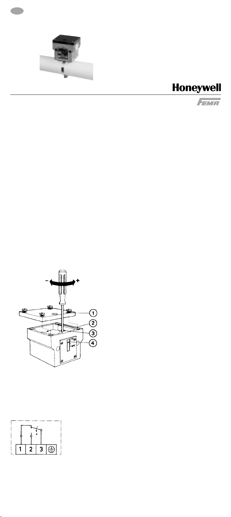
Einstellung
1 Gehäusedeckel
2 Gehäuse
3 Einstellschraube
4 Sollwert
Nach Abnahme des Gehäusedeckels 1 kann
mittels eines Schraubendrehers die Einstellschraube 3 und somit der Sollwert 4 auf den
gewünschten Wert gestellt werden
Anlegethermostate, Serie TKM
Montage- und Bedienungsanleitung
D
FEMA Regelgeräte
Honeywell GmbH · Böblinger Straße 17 · D-71101 Schönaich
Telefon 0 70 31 / 6 37-02 · Telefax 0 70 31 / 6 37-8 50
7156.724 · MU2B-0242GE51 R0504 www.honeywell.de/fema
Elektrischer Anschluss
Bei steigender Temperatur:
3-1 öffnet, 3-2 schließt
Bei fallender Temperatur:
3-2 öffnet, 3-1 schließt
Page 2
Important note
Before mounting the strap-on thermostate use
the heat conducting compound between the
pipe and the contact face of the sensor to
improve the sensitivity.
Please take care that the space between
sensor and pipe is completely filled with the
heat conducting compound.
Technical Data:
Mounting position: Any
Contact complement: single-pole changeover
Switching capacity: 8 (5) A 250 V AC
Max. media temperature: 100 ºC
Max. ambiente temperature at the switching
device: 70 ºC
Switching differential: ca. 6 K, not adjustable
Type of protection: IP54 in case of vertical
mounting
Cable entry: M 16
1,5
Max. cable diameter: 12 mm
Installation
The fast responding sensor system is also selfmonitoring. If the sensor is broken or
damaged, the thermostat behaves as through
the temperature had exceeded the set value,
is switched off towards the safe side.
It is important that the surface of the pipe is
carefully cleaned and free from dirt, scale
and paint before fitting the sensor. The tension
band included with each thermostat enables
the contact thermostats to be attached to
pipes of nominal diameters |” and 2”.
Before mounting the strap-on thermostate use
the heat conducting compound between the
pipe and the contact face of the sensor to
improve the sensitivity.
Please take care that the space between
sensor and pipe is completely filled with the
heat conducting compound.
Adjustment
1 Casing cover
2 Casing
3 Adjusting screw
4 Setpoint
After removal of the terminal box cover 1 the
adjustment screw 4 can be adjusted with
screwdriver.
Strap-on Thermostat Series TKM
FEMA Controls
Honeywell GmbH · Böblinger Straße 17 · D-71101 Schönaich
Phone 0 70 31 / 6 37-02 · Fax 0 70 31 / 6 37-8 50
7156.723/8 · MU2B-0242GE51 R0504 www.honeywell.de/fema
Electrical connection
As the temperature rises:
3-1 opens, 3-2 closes
As the temperature falls:
3-2 opens, 3-1 closes
GB
Assembly- and Operating Instructions
 Loading...