

Honeywell T921A, T921B, T921E, T921F, T921G User Manual
T921A,B,E-G Proportional
Control Thermostats
T921 Thermostats provide 3-wire, low voltage
proportional control for Series 90 (135 ohm) valve
motors, damper motors, and balancing relays in
heating or cooling system applications.
■■ T921A ■■ T921B ■■ T921E ■■ T921F ■■ T921G
■ Accessory faceplates available for horizontal mount-
ing of T921A,B,E models.
■ COOL-HEAT changeover switch in the T921B.
■ Night setback mechanism and switch in the T921E.
■ A spdt (single pole double throw) Class 2 auxiliary
switch in the T921F,G, which operates at the low
(T921F) and high (T921G) end of the throttling
range.
■ A bellows element adjusts the potentiometer slider
to regulate motor operation.
■ Various temperature ranges are available.
■ All models are available with a thermometer and a
locking cover.
CONTENTS
Specifications .................................................2
Ordering Information..................................... 2
Installation .....................................................4
Setting and Adjusting .....................................7
Operation .......................................................7
J. D. • Rev. 1-94 • ©Honeywell Inc. 1994 • Form Number 60-2242—2
1 60-2242—2

T921A,B,E-G
SPECIFICATIONS • ORDERING INFORMATION
Specifications
TRADELINE® MODELS
TRADELINE® models are selected and packaged to
provide ease of stocking, ease of handling and maximum
replacement value. TRADELINE® model specifications
are the same as those of the standard models except as noted
below.
TRADELINE® MODEL AVAILABLE:
T921A Thermostat for vertical or horizontal mounting.
TEMPERATURE RANGE AND SCALE:
56° to 84° F [13° to 29°].
ADDITIONAL FEATURES:
• TRADELINE® packed with cross-reference label
and special TRADELINE® instructions.
• T6051A may be used in electric heat systems.
• They all include slotted sides and an add-on faceplate
to allow the thermostat to be mounted horizontally.
They also include the 127246A Adapter Plate Assembly for vertical mounting on a horizontal conduit
box or for horizontal mounting on a vertical conduit
box.
STANDARD MODEL
MODELS:
T921A: Heating or cooling applications.
T921B: Is the same as the T921A but includes a cool-
heat changeover switch.
T921E: Includes a switch and heater that provide a night
setback of approximately 10° F [5.5° C].
T921F: Includes an spdt low voltage Class 2 auxiliary
switch that operates at the low end of the throttling
range.
T921G: Includes an spdt low voltage Class 2 auxiliary
switch that operates at the high end of the throttling
range.
SETTING ADJUSTMENT RANGE:
T921A,B,E-G: 56° to 84° F [13° to 29° C].
T921A,B,E-G: 13° to 29° C [56° to 84° F].
T921A: 42° to 75° F [ 5° to 24° C].
T921A,B: 66° to 95° F [19° to 35° C].
THERMOMETER: Bimetal. Scale ranges T921A only:
45° to 75° F [7° to 24° C]. All other models: 60° to 90° F
[16° to 32° C], 15° to 35° C [59° to 95° F]. T921A is also
available with a blank cover and no thermometer.
AUXILIARY SWITCH DIFFERENTIAL:
T921F: 2° F [1° C].
T921G: 1° F [0.5° C].
THROTTLING RANGE:
Fixed.
T921A: 2.5° F [1° C] midscale.
T921B,E: 4° F [2° C].
T921F: 6° F [3° C].
T921G: 5° F [2.5° C].
Variable.
T921A model available with potentiometer for 5° to
6° F [2.5 to 3° C] throttling range.
ELECTRICAL RATINGS:
Voltage: 24 to 30 Vac.
Auxiliary Switch Contact Rating (When Used For Pilot
Duty): 100 VA at 30 Vac.
DIMENSIONS:
Refer to Fig. 1.
ACCESSORIES (ORDER SEPARATELY):
127246A Adapter Plate Assembly for mounting all mod-
els vertically on a horizontal conduit box. (T921
models are shipped with a faceplate for vertical mounting.)
When mounting the T921A,B,E horizontally, see
Table 1 to order the faceplate with the appropriate
scale. NOTE: Do not mount the T921F,G horizontally.
34297B Thermostat Guard Assembly and 138541A
Mounting Plate.
133722A Thermostat Guard (clear plastic cover).
133723A Thermostat Guard (beige plastic cover).
Ordering Information
When purchasing replacement and modernization products from your TRADELINE® wholesaler or your distributor, refer to the
TRADELINE
1. Model number.
2. Scale range.
3. Accessories, if desired.
If you have additional questions, need further information, or want to comment on our products or services, please write or phone:
1. You local Honeywell Home and Building Control Sales Office (check the white pages of the phone directory).
2. Home And Building Control Customer Satisfaction
60-2242—2 2
®
Catalog or price sheets for complete ordering number or specify—
Honeywell Inc., 1885 Douglas Drive North
Minneapolis, Minnesota 55422 1-800-468-1502
(In Canada—Honeywell Limited/Honeywell Limitee, 740 Ellesmere Road, Scarborough, Ontario M1P 2V9) International Sales
and Service Offices in all Principal Cities of the world. Manufacturing in Australia, Canada, Finland, France, Germany, Japan,
Mexico, Netherlands, Spain, Taiwan, United Kingdom, U.S.A.
T921A,B,E-G
SPECIFICATIONS
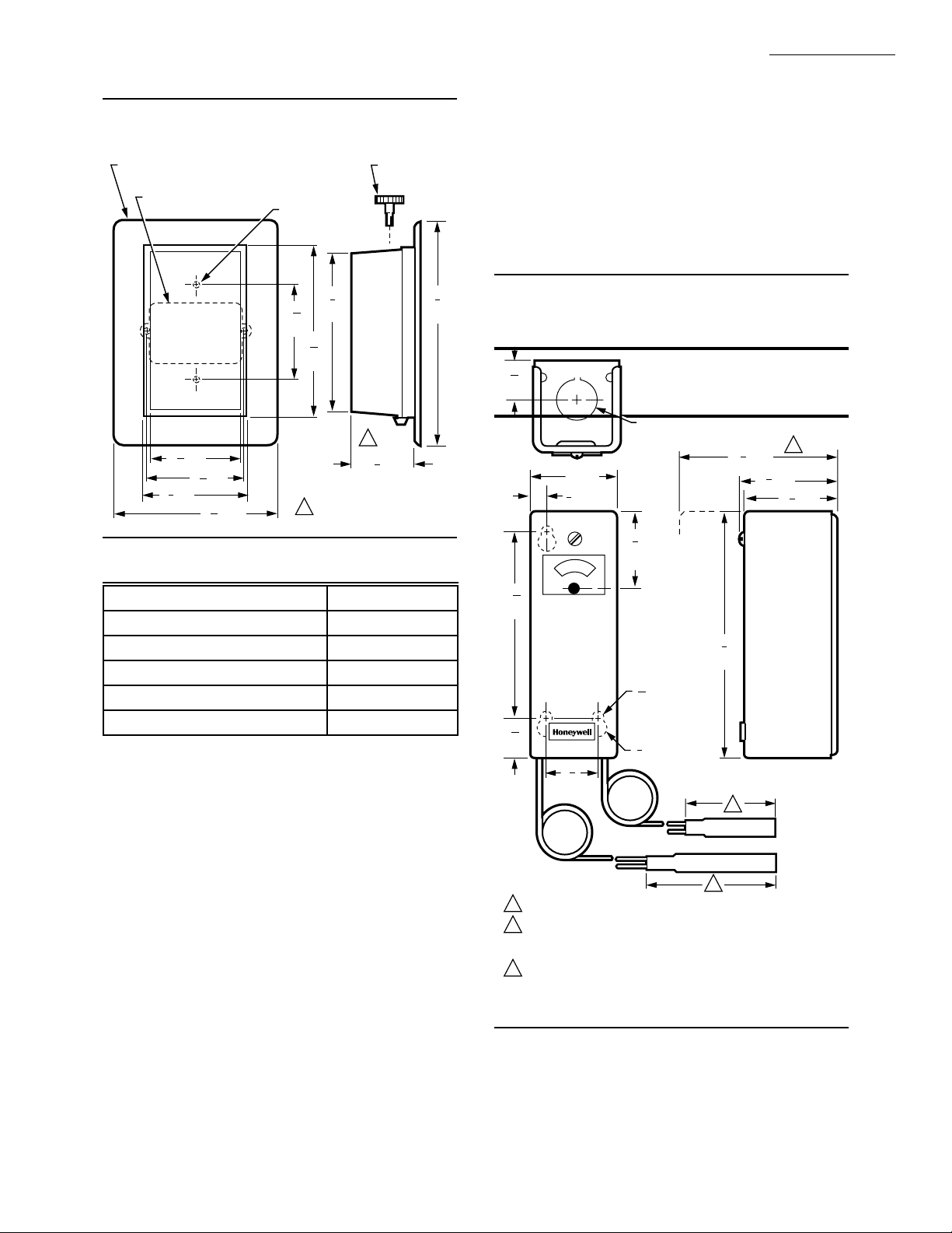
Fig. 1—T921 approximate installation dimensions in in. [mm].
ACCESSORY ADAPTER PLATE (127246A) FOR
MOUNTING ON HORIZONTAL CONDUIT BOX
HORIZONTAL CONDUIT BOX
1
3 [78]
16
5
3 [84]
16
3
3 [86]
8
5
5 [135]
16
FOR VERTICAL
CONDUIT BOX (2)
5
3
16
[84]
11
5
16
[145]
2-11/16 [69] INCHES FOR
1
T921F, G MODELS.
5
[137]
3
8
SETTING
ADJUSTMENT
KNOB
1
1
2 [57]
4
7
[194]
M9107
TABLE 1—ACCESSORY FACEPLATE.
Scale Part No.
56° to 84° F [13° to 29° C] 135135A
13° to 29° C [56° to 84° F] 135135B
42° to 75° F [5° to 24° C] 135135C
66° to 95° F [19° to 35° C] 135135D
56° to 84° F [13° to 29° C] 135135C
a
Blank faceplate.
a
REPLACEMENT PART:
130224 Locking Cover Knob.
OPTIONAL SPECIFICATION (USING THE T991B):
Alternate proportional control similar to the T921A, but
uses an outdoor temperature, automatic control point
reset.
T991B with 3-1/2: 1 reset and 50° to 120° F [10° to
49° C] temperature setting scale (when the outdoor
bulb is at 60° F [16° C]).
DIMENSIONS:
Refer to Fig. 2.
ACCESSORIES:
Compression fittings, immersion wells: Refer to the
appropriate specification or the TRADELINE® Catalog.
314439 Mounting Clips: For mounting a capillary tub-
ing (averaging element) in a duct.
7640HX Averaging Element Mounting Kit: For mount-
ing in existing installations where access to the duct
is impractical.
Q615A Enclosure: To protect the device when mounted
outside; splash proof.
801534 Calibration Wrench.
107324A Bulb Holder: For mounting the bulb in a duct.
34886A Outdoor Bulb Shield: To protect the outdoor
bulb mounting.
5
8
Fig. 2—T991B approximate installation
dimensions in in. [mm].
15
16
[24]
KNOCKOUT FOR 1/2 INCH
CONDUIT (BOTH ENDS)
1
4 [108]
4
2 [51]
3
[10]
8
3
1
4
[45]
3
4
16
[106]
5
[143]
7
[6]
32
DIAMETER (3)
15
16
[24]
1
1
4
[32]
1
OUTDOOR BULB SIZE VARIES INVERSELY WITH THE RESET RATIO.
2
INDOOR BULB LENGTH AND DIAMETER IS 4-1/2 [114] INCH BY
1/2 [13] INCH EXCEPT FOR THE AVERAGING ELEMENT WHICH IS
1/8 [3] INCH DIAMETER BY 12 FT. [3 M] LONG.
3
CLEARANCE NECESSARY TO REMOVE COVER.
3
[10]
8
DIAMETER
2
1
2 [57]
4
5
8
1
3
1
2 [57]
8
M9108
3 60-2242—2
 Loading...