

Honeywell T87N1026 Owner's Manual
69-1840EFS-07
T
A
E
H
•
F
F
O
•
L
O
O
C
6
F
A
N
O
N
•
7
•
A
8
U
T
O
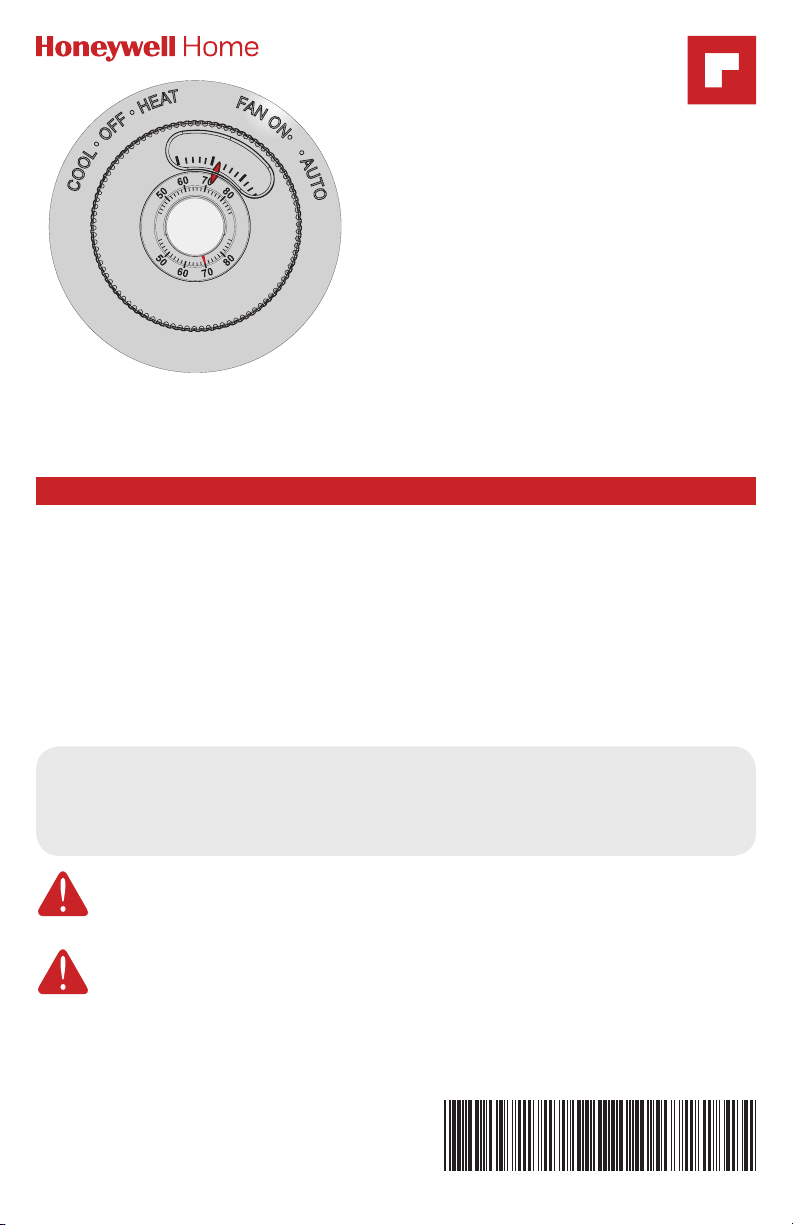
T87N Easy-To-See
The Round
Pre-installation checklist
®
TM
Owner’s Manual
English: Page 1
Mode d’emploi
Français: Page 6
Manual de Uso
Español: Página 11
Read before installing
T87N, T87N1026
Check package contents:
• Thermostat
• Wall anchors & screws (2 each)
• Owner's Manual
• Large Print Subbase Switch Labels
• Coverplate
Before you begin, make sure
you have:
• No. 2 Phillips & small pocket
screwdrivers
• Hammer
• Level (optional)
• Pencil
• Drill and bit (3/16” for drywall, 7/32”
for plaster)
Must be installed by a trained, experienced technician
Read these instructions carefully. Failure to follow these instructions
can damage the product or cause a hazardous condition.
CAUTION: ELECTRICAL HAZARD
Can cause electrical shock or equipment damage. Disconnect power before
beginning installation.
MERCURY NOTICE
If this product is replacing a control that contains mercury in a sealed tube, do not
place the old control in the trash. Contact your local waste management authority for
instructions regarding recycling and proper disposal.
This thermostat contains a Lithium battery which may contain Perchlorate material.
Perchlorate Material—special handling may apply,
See www.dtsc.ca.gov/hazardouswaste/perchlorate
The Round® Ea sy -To-S ee
TM
T87N Easy-To-SeeTM • Owner's Manual
Product application
This thermostat provides electronic control of 24 VAC single-stage heating
and cooling systems.
System Types
• Gas, oil, or electric heat with air
conditioning
• Warm air, hot water, high-efficiency
furnaces, heat pumps, steam, gravity
• Heat only
• Heat only with fan
• Cool only
System Settings
• Heat, Off, Cool
Fan Settings
• Auto, On
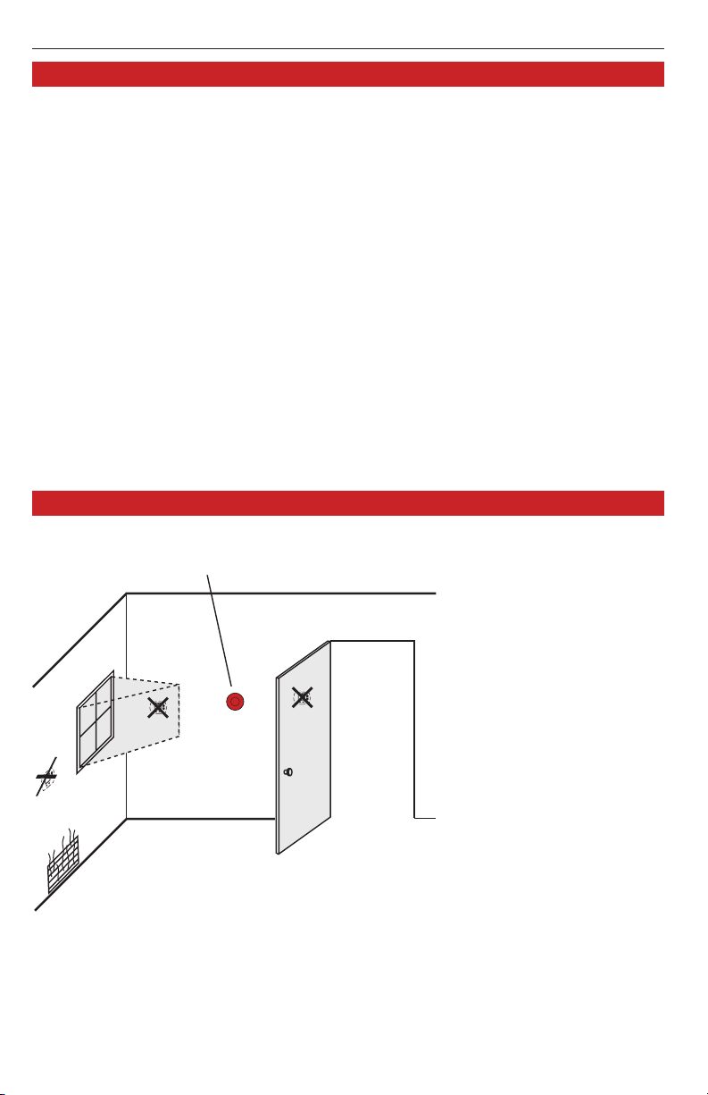
Installation tips
Install the thermostat about 5 feet (1.5 m) above the floor in an
area with good air circulation at average temperature.
Specifications
Temperature Range
• 40° to 90°F (4.5° to 32°C)
Shipping Temperature
• 20° to 120°F (28.9° to 48.9°C)
Operating Relative Humidity
• 5% to 90% (non-condensing)
Electrical Ratings
• Voltage: 2030 VAC
• Running current:0.021.0 A,
50/60 Hz
NO
NO
Do not install in locations where the thermostat can be affected by:
• Drafts or dead spots behind doors and in corners
• Hot or cold air from ducts
• Sunlight or radiant heat from appliances
• Concealed pipes or chimneys
• Unheated/uncooled areas such as an outside wall behind the
thermostat
69-1840EFS—07 2
NO
English: Page 1 • Français: Page 6 • Español: Página 11
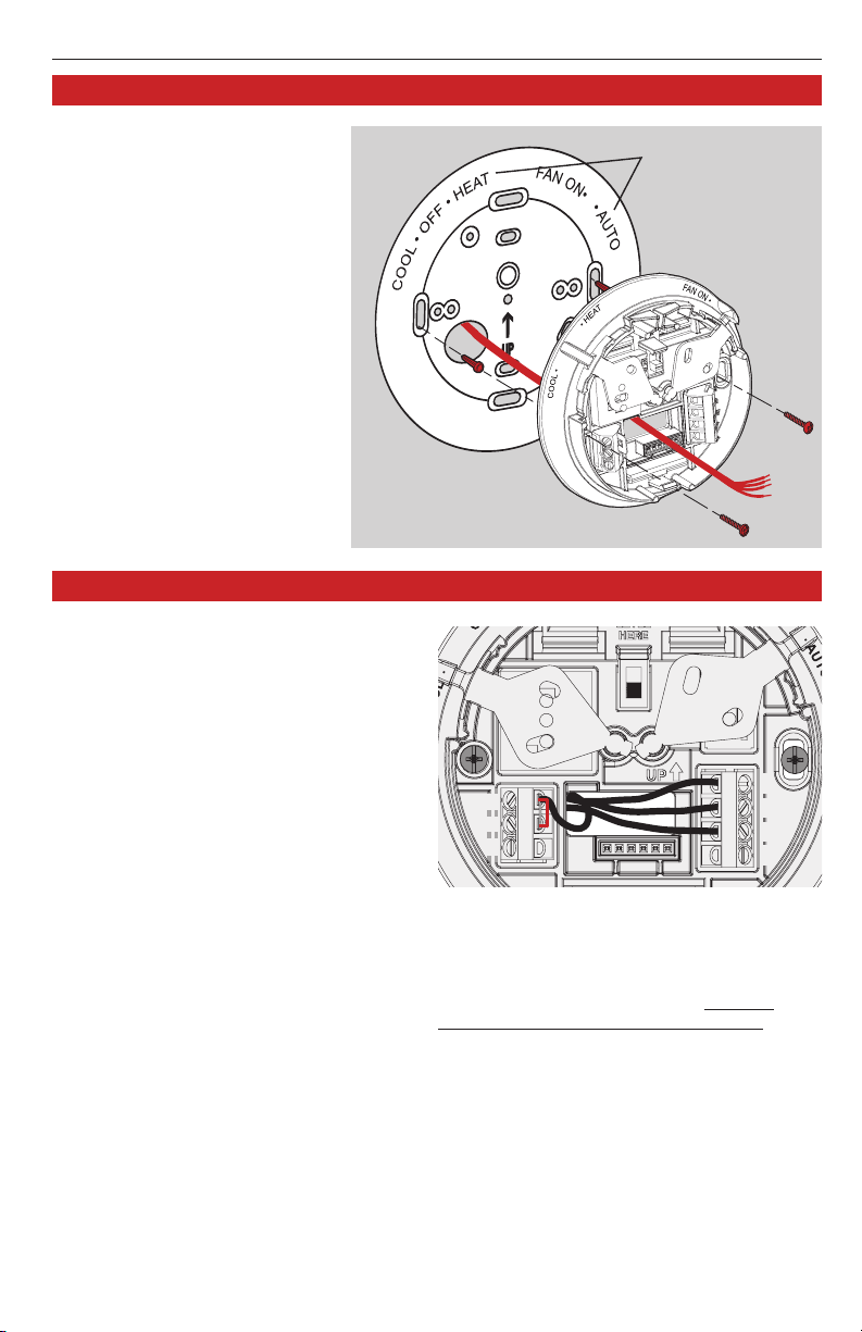
Subbase and base installation
1. Pull wires through wire
hole. Position coverplate
on wall, level and mark hole
positions.
2. Drill holes (3/16” for
drywall, 7/32” for plaster)
and tap in supplied wall
anchors.
3. Pull wire through
coverplate and subbase,
position over anchors,
then insert and tighten
mounting screws. Check
level if desired.
4. Apply the large-print labels
to the coverplate, matching
the labels on the subbase.
Wiring
1. Loosen screw terminals, insert wires
into terminal block, then re-tighten
screws.
2. Push excess wire back into the wall
opening.
3. Plug the wall opening with
nonflammable insulation to prevent
drafts from affecting thermostat
operation.
Terminal Designations
W Heat relay.
Y Compressor contactor.
G Fan relay.
O Heat pump changeover valve
energized in cooling.
Rc Cooling power. Connect to
secondary side of cooling system
transformer.
R Heating power. Connect to
secondary side of heating system
transformer.
B Heat pump changeover valve
energized in heating.
Coverplate
NOTES
R & Rc terminals
In single-transformer system, leave metal
jumper in place between
metal jumper if two-transformer system.
Heat pump systems
If wiring to a heat pump, use a small piece of
wire (not supplied) to connect terminals W
and Y.
Wire specifications
Use 18 to 22-gauge thermostat wire.
Shielded cable is not required.
Rc
Large-print
subbase switch
labels
Subbase
E
F
G
R
O
R & Rc. Remove
W
Y
B
3 69-1840EFS—07
T87N Easy-To-SeeTM • Owner's Manual
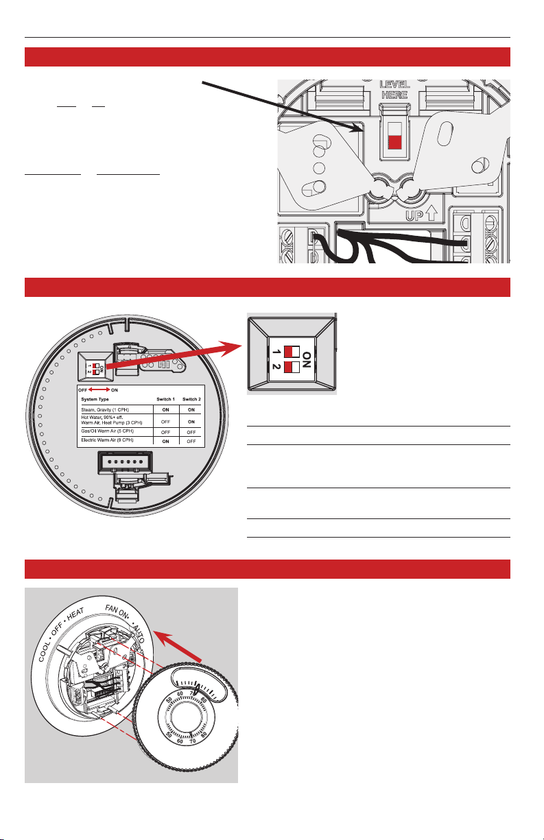
Fan operation settings
Fan operation settings:
F: For gas or oil heating systems, leave the
fan operation switch in this factory-set
position (for systems that control the fan
in a call for heat).
E: Change the switch to this setting for
heat pump or electric heat systems. (This
setting is for systems that allow the thermostat to control the fan in a call for heat,
if a fan wire is connected to the G terminal.)
Cycle rate settings
E
F
Move the cycle rate switches
to the proper setting for your
system (see table below).
Heating System Switch 1 Switch 2
Steam or gravity (1 CPH) On On
High efficiency warm air Off On
(90%+), hot water, or
heat pump (3 CPH)
Gas or oil warm air Off Off
(factory setting) (5 CPH)
Electric warm air (9 CPH) On Off
Thermostat mounting
Coverplate
and subbase
7
6
Thermostat
69-1840EFS—07 4
Align the slots on the base with tabs on the
thermostat, then push gently until the
thermostat snaps into place.
8
Operation
C
O
O
L
•
O
F
F
•
H
E
A
T
F
A
N
O
N
•
•
A
U
T
O
6
7
8
English: Page 1 • Français: Page 6 • Español: Página 11
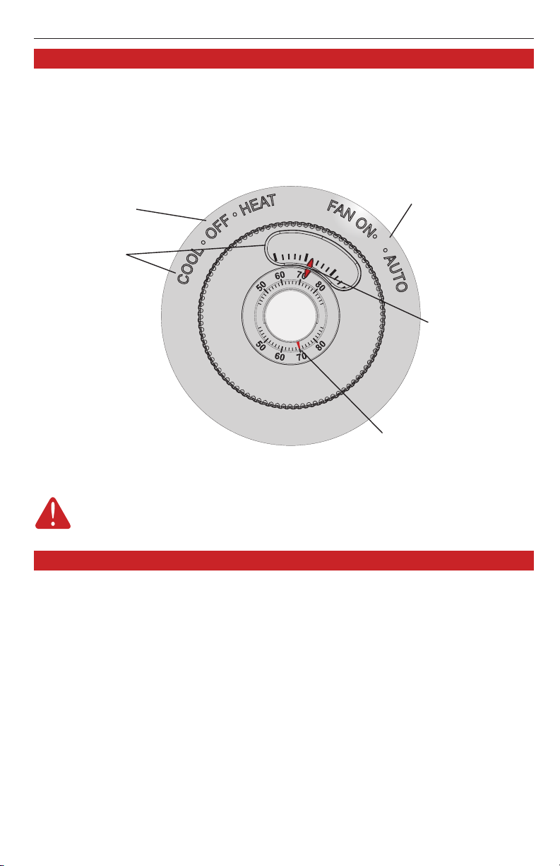
System switch
• Cool: Controls the cooling
system.
• Heat: Controls the heating
system.
• Off: All systems are
off.
Markings
Enlarged,
raised
numbers
indicate
temperature
range by
touch or
sight. The
large 5, 6, 7
and 8 mean 50,
60, 70 and 80°F,
respectively.
Fan switch
• On: Fan runs
continuously.
• Auto: Fan runs only
when heating or cooling
system is on.
Temperature
setting
Rotate to
set, a click is
heard every
two degrees
as the
temperature
is adjusted.
Temperature
Current indoor
temperature.
CAUTION: EQUIPMENT DAMAGE HAZARD
Do not operate cooling system when outdoor temperature is below 50°F (10°C).
Limited 5-year warranty
Resideo warrants this product, excluding battery, to be free
from defects in workmanship or materials, under normal use
and service, for a period of five (5) years from the date of first
purchase by the original purchaser. If at any time during the
warranty period the product is determined to be defective due to
workmanship or materials, Resideo shall repair or replace it (at
Resideo’s option).
If the product is defective,
(i) return it, with a bill of sale or other dated proof of purchase, to
the place from which you purchased it; or
(ii) call Resideo Customer Care at 18004681502. Customer
Care will make the determination whether the product should be
returned to the following address: Resideo Return Goods, 1985
Douglas Dr. N., Golden Valley, MN 55422, or whether a replacement product can be sent to you.
This warranty does not cover removal or reinstallation costs. This
warranty shall not apply if it is shown by Resideo that the defect
was caused by damage which occurred while the product was in
the possession of a consumer.
Resideo’s sole responsibility shall be to repair or replace the
product within the terms stated above. RESIDEO SHALL NOT
BE LIABLE FOR ANY LOSS OR DAMAGE OF ANY KIND, IN
CLUDING ANY INCIDENTAL OR CONSEQUENTIAL DAMAGES
5 69-1840EFS—07
RESULTING, DIRECTLY OR INDIRECTLY, FROM ANY BREACH
OF ANY WARRANTY, EXPRESS OR IMPLIED, OR ANY OTHER
FAILURE OF THIS PRODUCT.
Some states do not allow the exclusion or limitation of incidental or consequential damages, so this limitation may not apply
to you.
THIS WARRANTY IS THE ONLY EXPRESS WARRANTY RESIDEO
MAKES ON THIS PRODUCT. THE DURATION OF ANY IMPLIED
WARRANTIES, INCLUDING THE WARRANTIES OF MERCHANT
ABILITY AND FITNESS FOR A PARTICULAR PURPOSE, IS
HEREBY LIMITED TO THE FIVE YEAR DURATION OF THIS
WARRANTY. Some states do not allow limitations on how long
an implied warranty lasts, so the above limitation may not apply
to you.
This warranty gives you specific legal rights, and you may
have other rights which vary from state to state. If you have
any questions concerning this warranty, please write Resideo
Customer Care, 1985 Douglas Dr, Golden Valley, MN 55422 or
call 18004681502.
 Loading...