

Page 1
T87F
Easy-to-See™ Thermostats
INSTALLATION INSTRUCTIONS
APPLICATION
The Easy-to-See™ 24 Vac Thermostats are:
Model Application Includes
Heating or
T87F
Heating/Cooling
a
For heating/cooling, order the Q539 Subbase, which
provides System and Fan switches at the thermostat
location.
The thermostat features a raised setpoint knob for easy
adjustment, a cover ring with large embossed numbers
for easy reading and an audible click with indents every
two degrees as the dial is turned.
MERCURY NOTICE
If this control is replacing a control that contains
mercury in a sealed tube, do not place your old
control in the trash. Dispose of properly.
Contact your local waste management authority
for instructions regarding recycling and the
proper disposal of an old control.
T87F3467/T87F5199
a
Thermostats and
137421A Wallplate.
INSTALLATION
When Installing this Product. . .
1. Read these instructions carefully. Failure to follow
them could cause a hazardous condition.
2. Check the ratings given in the instructions and on
the product to make sure the product is suitable for
your application.
3. Installer must be a trained experienced service
technician.
4. After installation is complete, check out product
operation as provided in these instructions.
CAUTION
1. Disconnect power supply to prevent electrical
shock or equipment damage.
2. To prevent interference with the thermostat
linkage, keep wire length to a minimum and
run wires as close as possible to the subbase.
3. Do not overtighten thermostat captive
mounting screws, because damage to
subbase threads can result.
4. Do not short across coil terminals on relay.
This can burn out the thermostat heat
anticipator.
IMPORTANT
An incorrectly leveled thermostat can cause the
temperature control to deviate from setpoint.
Location
Install the thermostat between 4 ft (1.2m) and 5 ft (1.5m)
above the floor. Locate in an area with good air circulation at average temperature.
NOTE: Due to the height restrictions of some disabled
users, it may be necessary to lower the thermostat location to 4 ft (1.2m) above the floor.
Do not install the thermostat where it can be affected by:
— drafts, or dead spots behind doors and in corners.
— hot or cold air from ducts.
— radiant heat from sun or appliances.
— concealed pipes and chimneys.
— unheated (uncooled) areas such as an outside wall
behind the thermostat.
This thermostat is a precision instrument and was
carefully adjusted at the factory. Handle it carefully.
Mount Wallplate or Subbase
IMPORTANT
When using the thermostat with a Q539 Subbase, follow the mounting and wiring instructions furnished with the subbase.
NOTE: To mount the thermostat on an outlet box, order
129044A Adapter Ring Assembly.
® U.S. Registered Trademark
Copyright © 2002 Honeywell • • All Rights Reserved
69-0200-6
Page 2
T87F EASY-TO-SEE™ THERMOSTATS
A
)
)
1
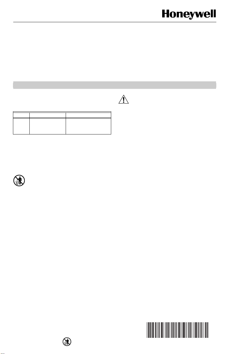
1. Hold wallplate in position and mark holes for
anchors. See Fig. 1. Obtain wall anchors locally.
Be careful that the wires do not fall back into the
wall opening. Set aside the wallplate. Drill four
3/16 in. (4.6 mm) holes and gently tap anchors into
the holes until flush with the wall.
2. Pull electrical wires through the wallplate opening.
See Fig. 1.
3. Secure the wallplate with the screws provided. Do
not fully tighten the screws.
4. Level the wallplate using a spirit level. See Fig. 1.
Firmly tighten the mounting screws. The mounting
holes provide for minor out-of-level adjustments.
MOLDED
POST (2)
MOUNTING
HOLE (3)
OPENING FOR
THERMOSTAT
WIRING (PLUG)t
(WITH INSULATION)
137421K WALLPLATE
SPIRIT
LEVEL
MOUNTING
SLOT (3)
M394B
Fig. 1. Level wallplate before mounting thermostat.
Wiring
All wiring must comply with local electrical codes and
ordinances. Follow equipment manufacturer ’s wiring
instructions when available.
The thermostat is adaptable to most two-wire and threewire (series 10 spdt) 24 Vac to 27 Vac heating systems.
To wire wallplate, proceed as follows:
1. Connect the system wires to the wallplate as
shown in Fig. 2 through 6. A letter code is near
each terminal for identification.
2. Firmly tighten each terminal screw.
3. Fit wires as close as possible to the wallplate. Push
excess wire back into hole.
4. Plug hole with nonflammable insulation to prevent
drafts from affecting the thermostat.
COMBINATION FAN
AND LIMIT CONTROL
L1
(HOT)
1
L2
BURNER
MOTOR
IGNITION
THERMOSTAT
Y
R
W
CAD CELL
POWER SUPPLY. PROVIDE DISCONNECT MEANS AND
1
OVERLOAD PROTECTION AS REQUIRED.
R8184 PROTECTORELAY OIL PRIMARY CONTAINS
2
INTERNAL TRANSFORMER
3
CONNECT OIL VALVE, IF APPLICABLE.
R8184G
T
2
T
F
F
OIL VALVE
WHITE
ORANGE
BLACK
Fig. 2. Typical oil heating system.
COMBINATION FAN AND
THERMOSTAT
R
W
GAS VALVE
TH
TR
TH
TR
1
POWER SUPPLY. PROVIDE DISCONNECT MEANS AND
OVERLOAD PROTECTION AS REQUIRED.
LIGHT CONTROLLER
LIMIT
TRANSFORMER
Fig. 3. Typical gas heating system.
THERMOSTAT
Y
R
COOLING
1
POWER SUPPLY. PROVIDE DISCONNECT MEANS AND
OVERLOAD PROTECTION AS REQUIRED.
Note that R and Y terminals are used.
CONTACTOR COIL
Fig. 4. Typical cooling only system.
FAN
FAN
MOTOR
FAN
MOTOR
M6105
L1
(HOT
L2
M610
3
L1
(HOT
L2
M6103
1
1
69-0200-6 2
Page 3
T87F EASY-TO-SEE™ THERMOSTATS
)
7
S
A
TRANSFORMER
B
W
R
COOL
POSITION
HEAT
POSITION
B
W
R
REMOTE
CHANGEOVER
SWITCH
OIL PRIMARY
JUMPER
TO THERMOSTAT
CONNECTIONS ON
SERIES 10 VALVE
AT BURNER
M6102
THERMOSTAT
Y
R
W
COOLING
CONTACTOR COIL
ISOLATING
RELAY
1
POWER SUPPLY. PROVIDE DISCONNECT MEANS AND OVERLOAD
PROTECTION AS REQUIRED.
Fig. 5. Typical heating-cooling application using a
remote-mounted system changeover switch.
LOW LIMIT
OPERATING CONTROL
T87F
Y
R
W
SERIES 10 OPEN
CIRCUIT HIGH LIMIT
Fig. 6. Replacing a series 10 thermostat.
Mount Thermostat
1. Remove the cover ring by pulling outward with
fingertips, pressing lightly on the dial with thumbs.
2. Carefully remove and discard the polystyrene
packing insert that protects the mercury switches
during shipment.
IMPORTANT
Set the heat anticipator NOW. If set too low
when mounted, it can burn out the heat anticipator when the heating system operates. See
Settings section for instructions.
3. Align the three captive mounting screws in the
thermostat with the posts on the wallplate. See
Fig. 7. These captive screws complete the electrical connections to the thermostat. Tighten the
three screws. Do not overtighten screws or dam-
age to the wallplate posts can result.
L1
(HOT
L2
M6104A
1
OPENING FOR THERMOSTAT
WIRING (PLUG WITH INSULATION)
THERMOSTAT
6
5
7
137421A
WALLPLATE
8
THERMOSTAT
COVER RING
Fig. 7. Mounting thermostat and 137421A Wallplate.
SETTINGS
Heat Anticipator Setting
Move the heat anticipator indicator to match the current
draw of the heating primary control, or the anticipator
setting of the old thermostat. See Fig. 8. Indicator may be
moved with fingers or pencil point through hole. If the
current rating is not given, proceed as follows:
1. Remove the thermostat and have the power on.
2. Connect an ac ammeter of appropriate range
between the heating terminals (R or R
the subbase or wallplate.
3. After one minute, read the ammeter and record the
reading.
4. Set the anticipator to match the ammeter reading
and mount the thermostat.
1.0
.8
.6
.5
.4
.3
CALE
HOLE SUITABLE FOR
PENCIL POINT
TO MOVE INDICATOR
Fig. 8. Adjust heat anticipator to match current rating
of the heating primary control.
NOTE: Move the indicator to a larger number
.2
.12
.15
(example: from .4 to .45) to lengthen the
burn time and have fewer cycles per hour.
MOUNTING
SLOT (3)
CAPTIVE
MOUNTING
SCREWS (3)
and W) of
H
HEAT
ANTICIPATOR
INDICATOR
M1368
M382
3 69-0200-6
Page 4
T87F EASY-TO-SEE™ THERMOSTATS
Temperature Setting
Align the three posts of the cover ring with the three clips
on the thermostat; press firmly. Turn the clear dial to the
desired setpoint (upper scale). A click is heard and an
indent felt every two degrees on the dial as the setpoint is
adjusted. A deeper indent is felt at the 10 degree
increment marks. The indents make it easier to adjust for
energy savings and check the temperature setting.
The enlarged cover ring includes raised temperature
markings every two degrees F. Large, raised 5, 6, 7 and
8 numbers identify the 50°F, 60°F, 70°F and 80°F
setpoints.
Mount Switch Labels
Attach the included switch labels when using a Q539
Subbase. See Fig. 9. The system switch and one of the
two fan switch labels can be mounted on the decorative
cover ring (if used) or on the wall as follows:
1. After the thermostat and subbase are installed,
select the labels that read the same as the subbase.
2. Peel from the backing.
3. With the bottom edge of the label next to the sub-
base, align the dots on the label with the dots
molded into the subbase.
4. Press firmly.
FAN
70
70
7
ON
AUTO
8
80
80
M6100
HEAT
5
50
6
60
OFF
COOL
50
60
Fig. 9. Placing the Easy-to-See™
Subbase Switch labels.
CALIBRATION
Thermostat
The Easy-to-See Thermostats are accurately calibrated
at the factory. If the thermostat is accurately leveled and
still appears to be out of calibration, order 104994A
Calibration Wrench. Instructions for recalibrating are
included with the wrench.
CHECKOUT
Heating
Move the setpoint indicator to about 10°F (6°C) above
room temperature. If using a Q539 Subbase, move the
system switch to HEAT and the fan switch to AUTO. The
heating equipment should start and the fan should run.
Move the setting about 10°F (6°C) below room temperature. The heating equipment and fan should shut off.
Cooling
CAUTION
Equipment Damage Hazard
Operating cooling below 50°F can damage the
compressor.
If outside air or heat exchange medium (water) is
below 50°F (10°C), do not operate cooling.
Move the setpoint indicator to about 10°F (6°C) below
room temperature. If using a Q539 Subbase, move the
system switch to COOL and the fan switch to AUTO. The
cooling equipment should start and the fan should run.
Move the setting about 10°F (6°C) above room temperature. The cooling equipment and fan should shut off.
Fan
If using a Q539 Subbase, move the subbase system
switch to OFF, and the fan switch to ON. The fan should
run continuously. Move the fan switch to AUTO. In this
position, fan operation is controlled by the heating or
cooling system control circuit.
NOTE: Before leaving the installation, hang the large-
print Homeowner’s Guide from the thermostat. If
user desires Braille Homeowner’s Guide or additional information, instruct user to call
1-800-468-1502.
Automation and Control Solution s
Honeywell Inc. Honeywell Limited-Honeywell Limitée
1985 Douglas Dr 35 Dynamic Dr
Golden Valley, MN 55422 Scarborough, Ontario
69-0200-6 G.H. Rev. 8-02 www.honeywell.com/yourhome
M1V 4Z9
Printed in U.S.A. on recycled
paper containing at least 10%
post-consumer paper fibers.
 Loading...