

Page 1
T874/Q674
Thermostat/Subbase Combinations
Installation Instructions for the Trained Service Technician.
Application
The T874/Q674 Thermostat/Subbase combinations provide 24 to 30 Vac control for heat pump systems. See Table 1.
TABLE 1—T874/Q674 THERMOSTAT/SUBBASE COMBINATIONS.
Thermostat/ Number Changeover
T874N/Q674C 2 1 1 — OFF-AUTO AUTO-ON 5
T874N/Q674F 2 1 — 1 OFF-EM. HT.- AUTO-ON 6
T874R/Q674L 2 1 — 2
a
Q674 Subbase provides the wiring terminals, system switch and fan switch for system operation.
b
Provides manual changeover with the subbase system switch in COOL position.
a
Subbase
Model Heating Cooling Heating Cooling System Fan See Fig.
of Stages Stage Type of Switching
HEAT-AUTO-COOL
b
EM. HT.-HEAT- AUTO-ON 7
OFF-COOL
Operation
On a two-heat thermostat, the two stages of heat make
sequentially as the temperature drops. Make refers to the
mercury switch initiating a call for heat or cool.
There are about 2° F [1° C] between stages so that the
second stage makes only when the first stage cannot handle
the load. This is the interstage differential.
One or two LEDs (light emitting diodes) are included on
your subbase. Refer to the list below for specific meaning.
The CHECK LED lights when something needs to be
checked or done to maintain efficient operation of the system.
See your heating system instructions for the specific meaning.
The EM. HT. LED lights when the system switch is placed
in the EM. HT. position. Emergency heat is operating; in
most systems, the compressor has failed and the heat pump
is not operating.
The AUX. HT. LED lights when the auxiliary heat stage
is operating. The weather is cold enough that the first stage
cannot handle the load alone.
LEDs are not field replaceable or addable.
Recycling Notice
M3375
This control contains mercury in a sealed tube. Do not
place control in the trash at the end of its useful life.
If this control is replacing a control that contains mercury in
a sealed tube, do not place your old control in the trash.
Contact your local waste management authority for instructions regarding recycling and the proper disposal of this
control, or of an old control containing mercury in a sealed
tube.
If you have questions, call Honeywell at 1-800-468-1502.
Installation
WHEN INSTALLING THIS PRODUCT…
1. Read these instructions carefully. Failure to follow
them could cause a hazardous condition.
2. Check the ratings given in the instructions and on the
product to make sure the product is suitable for your application.
3. Installer must be a trained, experienced service technician.
4. After installation is complete, check out product operation as provided in these instructions.
CAUTION
1. Disconnect power supply to prevent electrical
shock and equipment damage.
2. To prevent interference with the thermostat linkage, keep wire length to a minimum and run
wires as close as possible to the subbase. Push
excess wire back into the hole and plug hole to
prevent drafts from affecting thermostat operation.
3. Do not overtighten thermostat captive mounting
screws because damage to subbase threads may
result.
4. Do not short across coil terminals on the relay.
This may burn out the thermostat heat
anticipator.
IMPORTANT: Thermostats are calibrated at the factory
using subbases mounted at true level. An inaccurately
leveled subbase will cause thermostat control deviation.
S. M. • Rev. 5-93 • • ©Honeywell Inc. 1993 • Form Number 60-1147—4
M3375
Page 2
LOCATION
Install the thermostat about 5 ft [1.5 m] above the floor in
an area with good air circulation at average temperature.
Do not install the thermostat where it can be affected by:
—drafts, or dead spots behind doors and in corners.
—hot or cold air from ducts.
—radiant heat from sun or appliances.
—concealed pipes and chimneys.
—unheated (uncooled) areas such as an outside wall
behind the thermostat.
MOUNTING THE SUBBASE
The thermostat subbase can be mounted on a vertical
outlet box, horizontal outlet box or directly on the wall.
1. If you must mount the subbase on a vertical outlet box,
order 193121A Adapter Assembly (Fig. 1). The as-sembly
includes an adapter ring, two screws and a cover plate to cover
marks on the wall. Install the ring and cover plate on the
vertical outlet box.
For a wall installation, hold subbase in position and mark
holes for anchors (Fig. 2). Obtain wall anchors locally. Take
care that the wires do not fall back into the wall opening. Set
aside subbase. Drill four 3/16 in. [4.8 mm] holes and gently
tap anchors into the holes until flush with the wall.
2. Pull wires through the cover plate (if used) and subbase
cable opening (Fig. 3).
3. Secure the cover plate (if used) and subbase with the
screws provided. Do not fully tighten the subbase screws.
4. Level the subbase using a spirit level, as shown in Fig.
3, and firmly tighten the subbase mounting screws. The
subbase mounting holes provide for minor out-of-level adjustments.
IMPORTANT: An incorrectly leveled subbase will cause
the temperature control to deviate from set point.
WIRING THE SUBBASE
IMPORTANT: Use 18-gauge color-coded thermostat cable
for proper wiring.
Disconnect power supply before beginning installation to
prevent electrical shock or equipment damage.
All wiring must comply with local electrical codes and
ordinances. Follow equipment manufacturer wiring instructions when available. To wire subbase, proceed as follows:
1. Connect the system wires to the subbase as shown in
Figs. 5-7. A letter code located near each terminal is for
identification. The terminal barrier permits straight or conventional wraparound wiring connection (Fig. 4).
2. Firmly tighten each terminal screw.
3. Fit wires as close as possible to the subbase. Push
excess wire back into the hole.
4. Plug hole with nonflammable insulation to prevent
drafts from affecting the thermostat.
MOUNTING THE THERMOSTAT
1. Remove the thermostat cover by pulling the bottom
edge of the cover outward and away from the base until it
snaps free of the mounting slots.
NOTE: The cover is hinged at the top and must be re-moved
by pulling outward at the bottom.
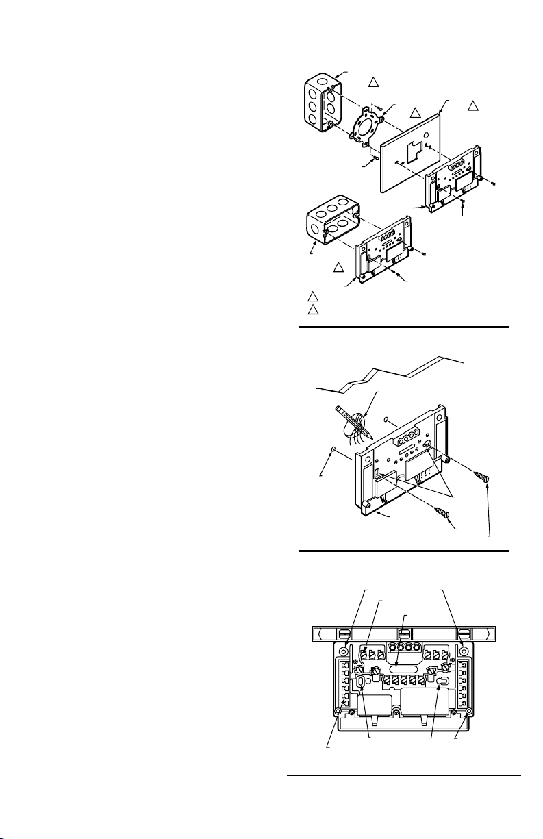
Fig. 1—Installation of Q674 Subbase on outlet box.
VERTICAL
OUTLET
1
BOX
2
MOUNTING
SCREWS (2)
COVER
PLATE
2
MOUNTING
SCREWS (2)
M925
ADAPTER
RING
MOUNTING
SCREWS (2)
SUBBASE
HORIZONTAL
OUTLET
BOX
1
SUBBASE
1 NOT INCLUDED WITH UNIT.
2 ACCESSORY PARTS AVAILABLE (193121A).
Fig. 2—Installation of Q674 Subbase on wall.
WALL
WIRES THROUGH
WALL OPENING
WALL
ANCHORS
(2)
SUBBASE
M926
Fig. 3—Subbase components and leveling
procedure.
SPIRIT LEVEL
TOP MOUNTING HOLES (2)
WIRING
TERMINAL
TO SPRING FINGER CONTACTS
ON THE THERMOSTAT
(UP TO 12)
MOUNTING HOLES (2)
THERMOSTAT
CABLE OPENING
MOUNTING
HOLES
MOUNTING
SCREWS (2)
POST (2) FOR
MOUNTING
THERMOSTAT
M927
60-1147-4
2
Page 3
2. Carefully remove and discard the polystyrene packing
insert that protects the mercury switches during shipment.
3. If LED indication (EM.HT., CHECK, etc.) is to be used
with the Q674 Subbase, install the preprinted insert under the
thermostat set point scale (Fig. 8). To install, push both
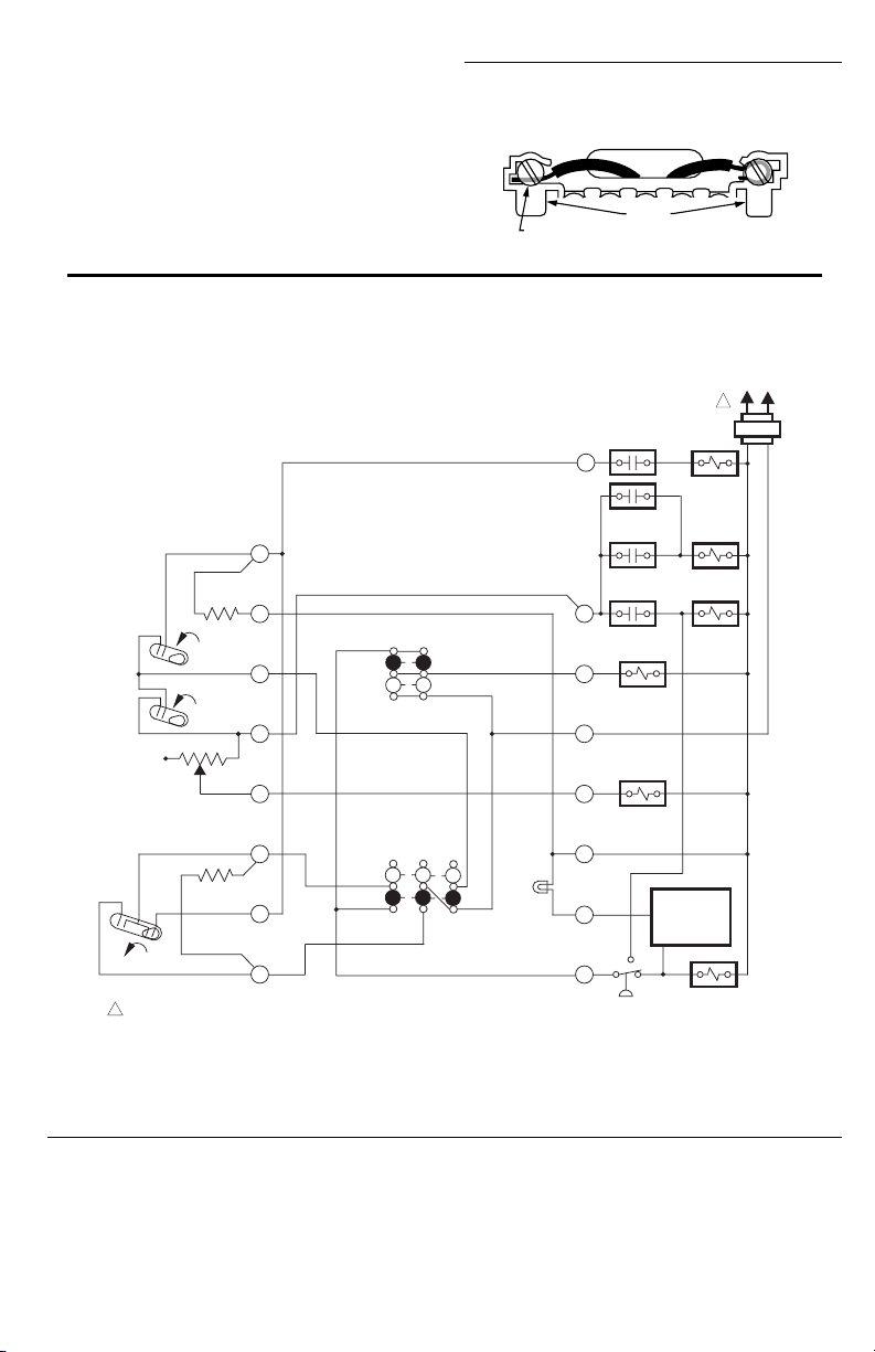
Fig. 4—Wiring connections.
FOR STRAIGHT
INSERTION–
STRIP 5/16 in. [8 mm]
thermostat set point levers to the far ends of the thermostat. Use
index finger to gently pull out the plastic set point scale about
1/4 in. [6 mm]. Drop insert into recessed area behind set point
scale so that selected LEDs show. Make sure insert is completely seated in recessed area. Let set point scale pop back, and
SUBBASE TERMINAL SCREW
set levers to desired positions.
Fig. 5—Internal schematic and typical wiring diagram for T874N and Q674C.
BARRIER
DEFROST RELAY
CONTACT
W1
OUTDOOR
THERMOSTAT
FOR WRAPAROUND–
STRIP 7/16 in. [11 mm]
L2
1
REVERSING
RELAY
L1
(HOT)
M928
H1
ANTICIPATOR
FALL
H1
FALL
H2
H2 ANTICIPATOR
C1
ANTICIPATOR
C1
CO
RISE
POWER SUPPLY. PROVIDE DISCONNECT MEANS AND OVERLOAD PROTECTION AS
1
REQUIRED.
FAN
SWITCH
AUTO
ON
SYSTEM
SWITCH
OFF
AUTO
W3
W2
CHECK
LED
(GRN)
EM. HT. RELAY
CONTACT
EM. HT. RELAY
CONTACT
G
R
X
L
Y
FAN RELAY
HEAT
RELAY 1
HEAT
RELAY 2
HEAT
RELAY 3
OPTIONAL
COMPRESSOR
FAILURE
DEVICE
COMPRESSOR
CONTACTOR
M1860
60-1147-43
Page 4

Fig. 6—Internal schematic and typical wiring diagram for T874N and Q674F.
H1
ANTICIPATOR
H1
FALL
H2
ANTICIPATOR
H2
FALL
RISE
C1
1
C1
ANTICIPATOR
C0
POWER SUPPLY. PROVIDE DISCONNECT MEANS AND OVERLOAD PROTECTION AS REQUIRED.
FAN SWITCH
AUTO
ON
SYSTEM
SWITCH
EM. HT.
HEAT
AUTO
COOL
OFF
EM. HEAT
LED (RED)
CHECK
LED
(GREEN)
W1
W3
G
R
W2
E
X
L
Y
DEFROST
RELAY
EM.HT. RELAY
CONTACT
EM.HT. RELAY
CONTACT
HIGH
PRESSURE
SWITCH
OUTDOOR
THERMOSTAT
HEAT
RELAY 1
OPTIONAL
COMPRESSOR
FAILURE DEVICE
REVERSING
VALVE
HEAT
RELAY 2
HEAT
RELAY 3
FAN RELAY
1
EM. HEAT
RELAY
COMPRESSOR
CONTACTOR
L1
HOT
L2
M3686
60-1147-4
4
Page 5

Fig. 7—Internal schematic and typical wiring diagram for T874R and Q674L.
H1/C1
ANTICIPATOR
H1
C1
FALL
FAN SWITCH
H2
H2
ANTICIPATOR
FALL
POWER SUPPLY. PROVIDE DISCONNECT MEANS
1
AND OVERLOAD PROTECTION AS REQUIRED.
AUTO
SYSTEM
SWITCH
ON
EM. HT.
HEAT
OFF
COOL
R
W3
DEFROST
RELAY
W2
B
L
AUX. HEAT
LED (GREEN)
X2
X1
EM. HEAT
LED (RED)
E
G
LOW
AMBIENT
CUTOFF
Y
O
EM.HT. RELAY
CONTACT
EM.HT. RELAY
CONTACT
OUTDOOR
THERMOSTAT
HEAT
RELAY 1
DEFROST
RELAY
OPTIONAL COMP
FAILURE DEVICE
COMPRESSOR
CONTACTOR
COOL RELAY
HEAT
CONTACTOR 3
HEAT
CONTACTOR 2
HIGH LIMIT
SWITCH
REVERSING
VALVE
EM. HEAT
RELAY
FAN RELAY
HIGH
PRESSURE
SWITCH
1
M3685
L1
HOT
L2
4. Turn over thermostat base and note the spring fingers
that engage the subbase contacts. Make sure the spring
fingers are not bent flat. Flat fingers prevent proper electrical
contact with the subbase.
5. Set the second stage heat anticipation indicator to
match the current rating of the controlled equipment. See
Heat Anticipator Setting section. The first stage heat anticipator and the cooling anticipator are nonadjustable.
6. Note the two tabs on the top inside edge of the
thermostat base. The tabs fit into corresponding slots on top
of the subbase. Mount the thermostat on the subbase.
7. Align the two captive mounting screws in the thermostat base with the posts on the subbase (Fig. 9). Tighten both
screws. Do not overtighten screws because damage to
subbase posts can result.
Fig. 8—LED space location and adjustable lever
stops.
LED SPACE
TIGHTENING SCREW
ADJUSTABLE STOPS
M7557
60-1147-45
Page 6

Fig. 9—Mounting thermostat on subbase.
THERMOSTAT
MOUNTING SLOTS (2)
THERMOSTAT
MOUNTING POST (2)
50 60 70 80
SUBBASE
HEAT
50 60 70 80
TEMPERATURE SETTING
Fig. 11—Location of external components (T874N
shown).
HEATING
SET POINT
LEVER
COOL
HEAT
50 60 70 80
50 60 70 80
OPTIONAL LED
ENUNCIATION
XXX
XXXX
COOLING
SET POINT
LEVER
XXX
XXXXXXXXXXXX
50 60 70 80
COOL
THERMOSTAT
M936
CAPTIVE MOUNTING
SCREWS (2)
Settings
HEAT ANTICIPATOR SETTING
Set the adjustable heat anticipator to match the current
draw of the second stage heating primary control (Fig. 10). If
the primary control nameplate has no rating or if further
adjustment is necessary, use the following procedure to
determine the current draw of the second stage.
NOTE: The current draw of the heating stage must be measured
with the thermostat removed and the power on.
1. Connect an ac ammeter of appropriate range between
the W2 and R terminals on the subbase.
2. Move the system switch to HEAT or AUTO.
3. After one minute, read the ammeter and record the
reading.
4. After mounting the thermostat, set the adjustable heat
anticipator to match the reading measured in step 3.
Fig. 10—Stage two adjustable heat anticipator.
.10
.12
.15
.2
.3
.4
1.2
.8
MOVE INDICATOR
TO MATCH CURRENT
RATING OF PRIMARY CONTROL
.6
M3684
FAN
THERMOMETER
(WHEN PROVIDED)
AUTO
FAN
SWITCH
AUTO
OFF
HEATON
COOL
AUX RELAY
SYSTEM
SWITCH
M3525
The T874N has separate heating and cooling set point
levers; the T874R has one set point lever for heating and
cooling. Move the heating and cooling set point levers (Fig.
10) to the desired comfort positions. The minimum differential between heating and cooling set point is 3° F [2° C] on the
T874N.
SUBBASE SETTING
A description of the subbase switching positions that
control the system operation follows (Fig. 11).
SYSTEM SWITCH (some subbases do not have all of the
following functions):
OFF: Both the heating and cooling systems are off. If the
fan switch is in AUTO position, the cooling fan is also
off.
AUTO: Thermostat automatically changes between heat-
ing and cooling system operation, depending on the
indoor temperature.
HEAT: Heating system is automatically controlled by the
thermostat. Cooling system is off.
COOL: Cooling system is automatically controlled by the
thermostat. Heating system is off.
EM. HT.: Emergency heat relay is automatically con-
trolled by the thermostat. Cooling system is off.
FAN SWITCH
ON: Fan operates continuously.
AUTO: Fan operates automatically with heating and
cooling equipment as controlled by the thermostat.
To move the subbase switches to the desired control
positions, use thumb and index finger to slide lever. Lever
must stop over desired function indicator position for proper
circuit operation.
60-1147-4
6
Page 7

Checkout
HEATING
Move the system switch on the Q674 to HEAT or AUTO
(if used) and the fan switch to AUTO. Move the heating set
point lever on the T874 about 10° F [6° C] above room
temperature. Heating equipment should start and the fan
should run. Move the heat lever about 10° F [6° C] below
room temperature. The heating equipment and fan should
shut off.
NOTE: In heat pump applications, time delays are involved
before the compressor is activated to prevent short cy-
cling. The delays are provided by a timer, which prevents
the compressor from starting for several minutes after the
thermostat last turned the compressor off, or after the
system first received power.
COOLING
Move the system switch on the Q674 to COOL or AUTO
(if used) and the fan switch to AUTO. Move the cooling set
point lever on the T874 about 10° F [6° C] below room
temperature. The cooling equipment should start (see NOTE
above). Move the cool lever about 10° F [6° C] above room
temperature. The cooling equipment and fan should shut off.
FAN
Move the subbase system switch to OFF, and the fan
switch to ON. The fan should run continuously. Move the fan
switch to AUTO. In this position, fan operation is controlled
by the heating or cooling system control circuit.
Calibration
If the set point lever and the thermometer reading do
not agree:
1. Remove the thermostat cover by pulling up from the
bottom of cover until it clears the mounting slots.
2. Set the thermostat cover on a table near an accurate
thermometer.
3. Allow 10 or 15 minutes for cover thermometer to
sense area temperature; compare the readings. Be careful
not to touch the thermometer or breathe on it.
4. If the readings are the same, replace the cover and put
the system into operation.
5. If the readings are different, insert a small screwdriver in the thermometer slot (Fig. 12) and turn it until the
thermometers have the same reading.
6. Replace thermostat cover and put the system into
operation.
NOTE: Radiant heat from your hands will offset the ther-
mometer reading. After making each adjustment, wait 10
or 15 minutes for the thermometer to stabilize before
comparing.
Fig. 12—Thermometer calibration.
THERMOSTAT
T874 Thermostats are accurately calibrated at the factory.
They do not have provision for field calibration.
THERMOMETER
The thermometer in your thermostat has been accurately
calibrated at the factory. The thermometer should need
adjustment only if it has been dropped or shifted due to
mishandling.
M5070
60-1147-47
Page 8

Automation and Control Solutions
Honeywell International Inc.
1985 Douglas Drive North
Golden Valley, MN 55422
Honeywell Limited-Honeywell Limitée
35 Dynamic Drive
Scarborough, Ontario M1V 4Z9
60-1147 –4 S.M. Rev. 5-93
60-1147-4
8
www.honeywell.com/yourhome
 Loading...