

Honeywell Sensepoint RFD Technical Manual
Technical Manual
Sensepoint RFD
(0-20% LEL and 0-100% LEL)
Remote Flammable Detector

SENSEPOINT RFD OPERATING MANUAL RFDMAN MAN0843 Issue 3
2
1 Safety
Ensure that this Operating Manual is read and understand BEFORE installing / operating /
maintaining the equipment. Pay particular attention to Warnings and Cautions. All document
Warnings are listed here and repeated where appropriate at the start of the relevant
chapter(s) of this Operating Manual. Cautions appear in the sections/sub-sections of the
document where they apply.
WARNINGS
Sensepoint RFD is designed for installation and use in Zone 1 or 2 hazardous areas in Europe and
Class 1 Division 1 or 2 area applications in North America.
Installation must be in accordance with the recognized standards of the appropriate authority in the
country concerned.
Access to the interior of the detector, when carrying out any work, must only be conducted by
trained personnel.
Before carrying out any work ensure local regulations and site procedures are followed. Appropriate
standards must be followed to maintain the overall certification of the detector.
For installations where conduit is used, and the sensor is mounted directly to the Sensepoint RFD,
there must be a “Seal Fitting” installed within 18 inches of the Sensepoint RFD. For installations
where the sensor will be mounted remote from Sensepoint RFD, two “Seal Fittings” will be
required: One at the conduit entrance for the power/signal and one at the sensor wiring entrance.
The total distance of the location of these Seal Fittings is 18 inches. (e.g. Seal Fitting located within
10 inches of the power/signal entrance and the second Seal Fitting within 8 inches of the sensor
wiring entrance).
If using an anti-seize compound, the threads should be thinly coated with an approved silicone
free compound e.g. petroleum jelly
To reduce the risk of ignition of hazardous atmosphere, de-classify the area or disconnect the
equipment from the supply circuit before opening the detector enclosure. Keep assembly tightly
closed during operation.
Never attempt to open a junction box/enclosure or replace/refit the sensor in potentially
hazardous atmospheres.
The detector must be earthed/grounded for electrical safety and to limit the effects of radio frequency
interference. An earth/ground point is provided inside and outside the unit. Ensure that all
screens/armor are earthed/grounded at a single star point at the controller or detector - BUT NOT
BOTH - to prevent false alarms due to earth/ground loops.
Only replace the Remote Handheld Interface batteries in a non hazardous area. Only replace the
batteries with approved 'AAA' alkaline batteries, Energizer E92 or Duracell MN2400. Use only two
new batteries of the same type when replacing batteries. The Handheld Remote Interface has
no serviceable parts.
Do not tamper or in any way dis-assemble the sensor.
Do not expose to temperatures outside the recommended range.
Do not expose sensor to organic solvents or flammable liquids.
At the end of their working life, sensors and batteries must be disposed of in an environmentally
safe manner. Disposal should be according to local waste management requirements
and environmental legislation.
Alternatively, sensors may be securely packaged and returned to Hon eywell Analytics clearly marked
for environmental disposal.
Substitution of Handheld Remote Interface components may impair its Intrinsic Safety (IS). To prevent
ignition of flammable or combustible atmospheres, disconnect power before servicing the Handheld
Remote Interface.
SENSEPOINT RFD OPERATING MANUAL RFDMAN MAN0843 Issue 3
3
2 Information
In rush current is dependant on the type of power supply used. Typical in rush
current for Sensepoint RFD is 600mA. Measure the in rush current using the specific
power supply before installation to ensure suitability for your application.
Honeywell Analytics can take no responsibility for installation and/or use of its
equipment if this is not done in accordance with the appropriate issue and/or
amendment of the Operating Manual.
The reader of this Operating Manual should ensure that it is appropriate in all details
for the exact equipment to be installed and/or operated. If in doubt, contact
Honeywell Analytics for advice.
The following types of notices are used throughout this Operating Manual:
Note: Identifies useful/additional information.
Every effort has been made to ensure the accuracy of our documents, however,
Honeywell Analytics can assume no responsibility for any errors or omissions in our
documents or there consequences.
Honeywell Analytics greatly appreciates being informed of any errors or omissions
that may be found in the contents of any of our documents.
For information not covered in this document, or there is a requirement to send
comments/corrections about this document, please contact Honeywell Analytics
using the contact details given on the back page of this document.
Honeywell Analytics reserve the right to change or revise the information
supplied in this document without notice and without obligation to notify any
person or organization of such revision or change. If information is required
that does not appear in this document, contact the local distributor/agent or
Honeywell Analytics.
WARNING
Identifies a hazardous or unsafe practice which could result in severe injury
or death to personnel.
Caution: Identifies a hazardous or unsafe practice which could result in
minor injury to personnel, or product or property damage.

SENSEPOINT RFD OPERATING MANUAL RFDMAN MAN0843 Issue 3
4
3 Table of contents
1 Safety.............................................................................................................2
2 Information.....................................................................................................3
3 Table of contents ...........................................................................................4
4 Introduction ....................................................................................................5
4.1 Transmitter.................................................................................................. 5
4.2 Handheld Remote Interface (ZHC1) ...........................................................6
4.3 Gas sensors................................................................................................6
4.3.1 Sensepoint flammable gas sensors .........................................................6
4.3.2 705 Flammable gas sensors ....................................................................7
4.4 Accessories.................................................................................................7
5 Installation...................................................................................................... 8
5.1 Mounting and location of transmitter and sensors.......................................9
5.2 Mounting the transmitter .............................................................................9
5.3 Mounting the sensor .................................................................................10
5.3.1 Directly mounted sensor ........................................................................11
5.3.2 Remotely mounted sensor .....................................................................11
6 Electrical connections ..................................................................................12
6.1 Wiring schematics.....................................................................................13
6.1.1 Sensors with 20% LEL and 100% LEL ranges.......................................13
6.2 Terminal connections................................................................................14
6.3 Power........................................................................................................ 15
6.4 Cabling...................................................................................................... 15
7 Default configuration ....................................................................................17
8 Normal Operation.........................................................................................18
8.1 Display Screen..........................................................................................18
8.2 System Status...........................................................................................19
8.3 Handheld Remote Interface (ZHC1) .........................................................20
8.4 Menu functions..........................................................................................21
9 First time switch on ......................................................................................22
9.1 Calibration (menu P-00 and P-01) ............................................................22
10 User configuration......................................................................................25
10.1 P-02 Set alarm level 1 (or set fault relay)................................................25
10.2 P-03 Set alarm level 2.............................................................................25
10.3 P-04 Set relay 1 ......................................................................................25
10.4 P-05 Set relay 2 ......................................................................................26
10.5 P-06 Set sensor connection type and range ...........................................26
10.6 P-07 Set inhibit current and timeout........................................................27
10.7 P-08 Display software version.................................................................27
11 General Maintenance.................................................................................28
11.1 Operational Life.......................................................................................28
11.2 Sensor replacement................................................................................29
11.3 Handheld Remote Interface Battery Replacement..................................29
12 Error Codes and Troubleshooting ..............................................................30
13 General specifications................................................................................31
14 Ordering information ..................................................................................32
15 Warranty statement....................................................................................33
16 CE Certificate.............................................................................................34
17 Certification Nameplates............................................................................ 35
SENSEPOINT RFD OPERATING MANUAL RFDMAN MAN0843 Issue 3
5
4 Introduction
The Sensepoint RFD transmitter allows the user to either directly or remotely mount
a flammable gas sensor from the Sieger Sensepoint and 705 sensor range.
The remote sensors can be located up to 45 meters (147 feet) from the transmitter.
The transmitter features a display and two programmable relays for controlling
external equipment e.g. alarms, sirens, etc. It is configured via a Handheld Remote
Interface (ZHC1). This allows a single user to configure the transmitter without the
need to access internal components. The transmitter provides an industry standard
3-wire, 4-20mA source output for connection to a dedicated controller,
e.g. Honeywell Analytics Touchpoint 1 and 4 controllers (contact a distributor for
details), or to 3rd-party control equipment. Sensepoint RFD is suitable for use in
Zone 1 or 2 hazardous areas in Europe or Class 1 Division 1 or 2 area applications in
North America.
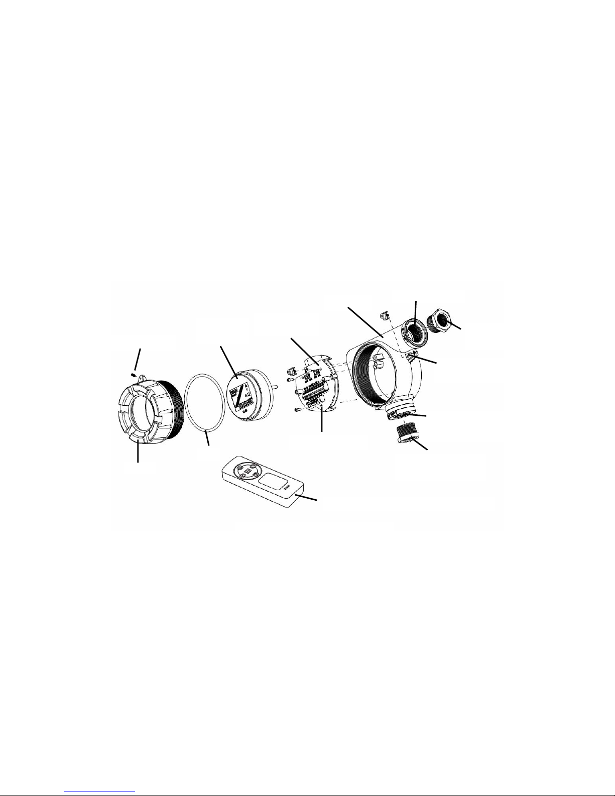
Sensepoint RFD comprises of the main parts as shown below.
4.1 Transmitter
The transmitter enclosure has two entries. The bottom entry allows either direct
connection of a sensor or the connection of cable or conduit from a remotely
mounted detector. The side entry is for connection of the transmitter outputs to
associated signaling equipment. Each entry is supplied with a ¾” NPT to M20
adaptor making it suitable for both European and North American installation
techniques. Sensepoint RFD is supplied complete with a mounting bracket for
installation on a wall or pole.
Cover
Locking screw
Seal
Display
Module
Internal Earth
Point
Enclosure
¾”NPT Entry
M20 Adaptor
External Earth
Point
Terminal Module
Sensor ¾”NPT
Entry
Sensor M20
Adaptor
Handheld Remote Interface (ZHC1)
Diagram 1: Exploded View

SENSEPOINT RFD OPERATING MANUAL RFDMAN MAN0843 Issue 3
6
4.2 Handheld Remote Interface (ZHC1)
The Handheld Remote Interface is Intrinsically Safe (IS) and allows non-intrusive
configuration of the detector, including calibration. Buttons are used for userinteraction with the transmitter and to navigate through a set of menus to set-up and
adjust the transmitter.
4.3 Gas sensors
Sensepoint RFD is designed to work with the flammable sensors from the Sieger
Sensepoint and 705 ranges. The Sensepoint range is ATEX approved for use
throughout Europe. The 705 range is UL approved for use in North America.
4.3.1 Sensepoint flammable gas sensors
Sensepoint flammable gas sensors are ATEX approved for use in Zone 1 or 2
hazardous areas. Two versions are available:
Standard LEL version
The standard LEL sensor is available for use in temperatures up to 80°C and detects
gas concentrations up to 100% LEL of a target gas with a resolution in the region of
1% LEL, depending on the gas being detected. The sensor is available with M20 or
¾” NPT threads.
High temperature LEL version
The high temperature version is available for use in temperatures up to 150°C and
ranges of 0-20% LEL up to 0-100% LEL depending on transmitter or controller.
The sensor is available with M20 or ¾” NPT threads.
Details of connecting these sensors with the Sensepoint RFD transmitter are given in
sections 5 and 6. For more sensor specific details, refer to the Technical Handbook
Part No. 2106M0502 or their individual manuals (Sensepoint HT Sensor Quick Start
Guide Part No: 2106M0523, Sensepoint LEL Operating Instructions Part No:
2106M0501).
Standard LEL
version
High temperature LEL version
Diagram 2: Sensepoint flammable sensors
SENSEPOINT RFD OPERATING MANUAL RFDMAN MAN0843 Issue 3
7
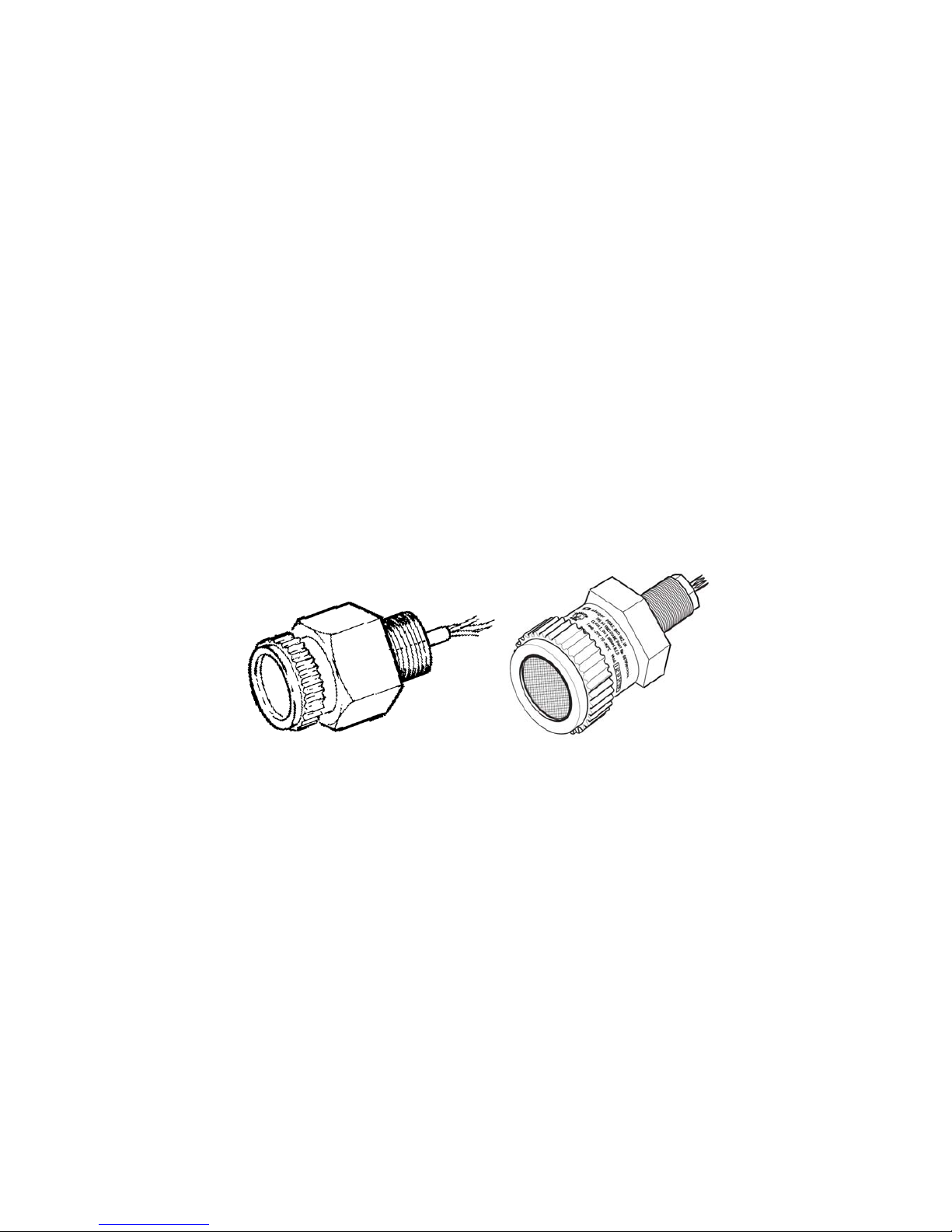
4.3.2 705 Flammable gas sensors
The 705 flammable gas sensors are UL certified for use in Class 1, Div. 1, Groups B,
C, D hazardous areas. The sensor comprises an aluminum housing containing a pair
of poison resistant detector elements, with a sintered stainless steel disc forming the
face of the sensor. The housing has a ¾” NPT mounting thread at one end and an
M36 accessory thread on the other end. A plastic Filter Housing screws on to the
accessory thread and holds the filter in position, if required. Two versions are
available:
Standard LEL version
The standard LEL sensor is available for use in temperatures up to +55°C and
detects gas concentrations up to 100% LEL.
High temperature LEL version
The high temperature version is available for use in temperatures up to +150°C and
ranges of 0-20% LEL up to 0-100% LEL depending on transmitter or controller.
Details of connecting these sensors to the Sensepoint RFD transmitter are given in
sections 5 and 6. For sensor more specific details, refer to their individual manuals
(00705M5002 standard temperature version and 00705M5010 high temperature
version).
4.4 Accessories
A range of accessories including flow housings, weather protection assemblies,
collecting cones, duct mounting kits and junction boxes are available for use with
these gas sensors. Refer to their individual manuals for further details.
Standard temperature
version
High temperature
version
Diagram 3: 705 Flammable sensors

SENSEPOINT RFD OPERATING MANUAL RFDMAN MAN0843 Issue 3
8
5 Installation
WARNINGS
Sensepoint RFD is designed for installation and use in Zone 1 or 2 hazardous areas in
Europe and Class 1 Division 1 or 2 area applications in North America.
Installation must be in accordance with the recognized standards of the appropriate
authority in the country concerned.
Access to the interior of the detector, when carrying out any work, must only be conducted
by trained personnel.
Before carrying out any work ensure local regulations and site procedures are followed.
Appropriate standards must be followed to maintain the overall certification of the detector.
For installations where conduit is used, and the sensor is mounted directly to the
Sensepoint RFD, there must be a “Seal Fitting” installed within 18 inches of the
Sensepoint RFD. For installations where the sensor will be mounted remote from
Sensepoint RFD, two “Seal Fittings” will be required: One at the conduit entrance for the
power/signal and one at the sensor wiring entrance. The total distance of the location of
these Seal Fittings is 18 inches. (e.g. Seal Fitting located within 10 inches of the
power/signal entrance and the second Seal Fitting within 8 inches of the sensor wiring
entrance).
If using an anti-seize compound, the threads should be thinly coated with an approved
silicone free compound e.g. petroleum jelly
To reduce the risk of ignition of hazardous atmosphere, de-classify the area or disconnect
the equipment from the supply circuit before opening the detector enclosure.
Keep assembly tightly closed during operation.
Never attempt to open a junction box/enclosure or replace/refit the sensor in potentially
hazardous atmospheres.
The detector must be earthed/grounded for electrical safety and to limit the effects of radio
frequency interference. An earth/ground point is provided inside and outside the unit.
Ensure that all screens/armor are earthed/grounded at a single star point at the controller or
detector - BUT NOT BOTH - to prevent false alarms due to earth/ground loops.
Only replace the Remote Handheld Interface batteries in a non hazardous area. Only replace
the batteries with approved 'AAA' alkaline batteries, Energizer E92 or Duracell MN2400.
Use only two new batteries of the same type when replacing batteries.
The Handheld Remote Interface has no serviceable parts.
Do not tamper or in any way dis-assemble the sensor.
Do not expose to temperatures outside the recommended range.
Do not expose sensor to organic solvents or flammable liquids.
At the end of their working life, sensors and batteries must be disposed of in an
environmentally safe manner. Disposal should be according to local waste management
requirements and environmental legislation.
Alternatively, sensors may be securely packaged and returned to Honeywell Analytics
clearly marked for environmental disposal.
Substitution of Handheld Remote Interface components may impair its Intrinsic Safety (IS).
To prevent ignition of flammable or combustible atmospheres, disconnect power before
servicing the Handheld Remote Interface.
SENSEPOINT RFD OPERATING MANUAL RFDMAN MAN0843 Issue 3
9
5.1 Mounting and location of transmitter and sensors
The sensor should be mounted where the gas is most likely to be present.
The following points should be noted when locating gas sensors.
• When locating sensors consider the possible damage caused by natural
events e.g. rain or flooding.
• Consider ease of access for functional testing and servicing.
• Consider how escaping gas may behave due to natural or forced air currents.
Note: The placement of sensors should be determined following the advice of experts
having specialist knowledge of gas dispersion, experts having knowledge of the
process plant system and equipment involved, safety and engineering personnel.
The agreement reached on the location of sensors should be recorded.
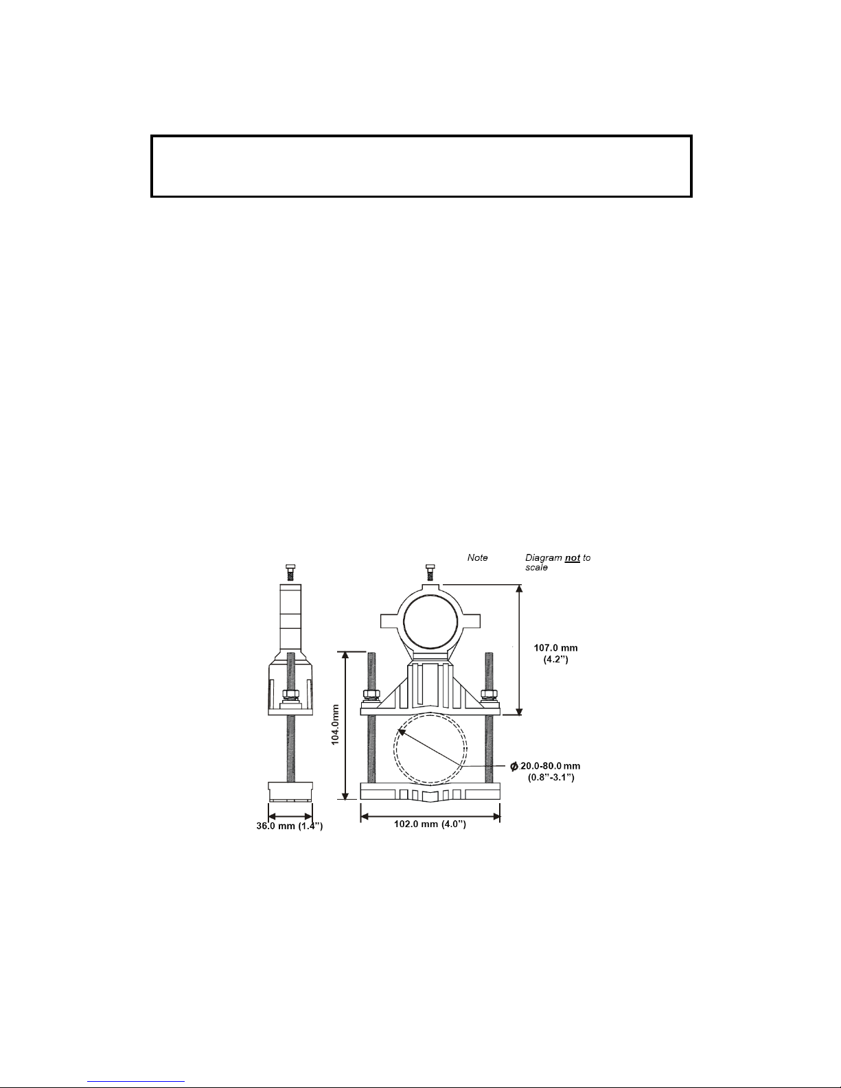
5.2 Mounting the transmitter
The Sensepoint RFD transmitter is supplied with a mounting bracket. The bracket
can be adjusted to fix the transmitter to a wall, or to a mounting pipe (horizontal or
vertical), 20.0-80.0mm (0.8 to 3.1 inches).
Caution: The location of the sensors should be made in accordance with
any relevant local and national legislation, standards or codes of practice.
Always replace sensors with a sensor of the same type.
Diagram 4: Mounting bracket
SENSEPOINT RFD OPERATING MANUAL RFDMAN MAN0843 Issue 3
10
To mount the Sensepoint RFD transmitter use the following procedure:
1. Loosen the lock-screw on the mounting bracket collar.
2. Pass the sensor entry neck of the transmitter through the collar as far as it
will go.
3. Securely tighten the mounting bracket collar lock- screw.
4. Mount the bracket to a pole or wall using appropriate fixings.
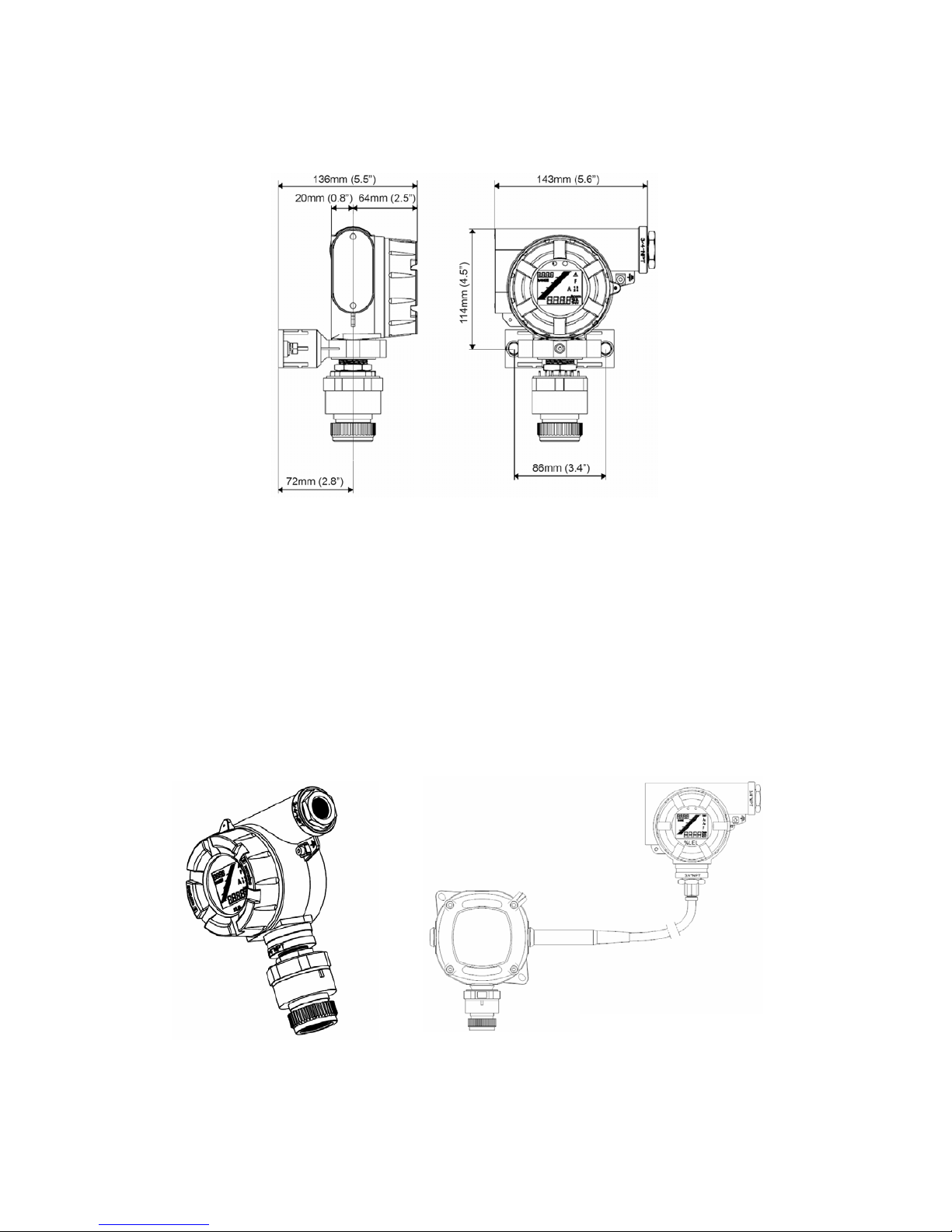
5.3 Mounting the sensor
The flammable gas sensors that can be used with the Sensepoint RFD transmitter
can be mounted directly to the bottom entry or remotely to a suitable junction box.
Directly mounted sensor
Remotely mounted sensor
Diagram 5: Outline dimensions
Diagram 6: Sensor mounting options

SENSEPOINT RFD OPERATING MANUAL RFDMAN MAN0843 Issue 3
11
5.3.1 Directly mounted sensor
To mount a sensor directly to the Sensepoint RFD transmitter follow the procedure
below.
1. Ensure that the ¾” NPT to M20 adaptor is fitted to the bottom entry if using a
sensor with an M20 thread, or is removed if using a sensor with a ¾” NPT
thread.
2. Remove the transmitter’s cover by loosening the locking screw and
unscrewing the cover in a counter-clockwise direction.
3. Remove the display module by firmly pulling it away from the enclosure
without twisting it.
4. Feed the sensor wires through the bottom entry into the terminal area.
5. Firmly screw the sensor thread into the bottom entry (or adaptor).
6. Connect the sensor wires to the terminals as shown in section 6.
5.3.2 Remotely mounted sensor
A remotely mounted sensor should be mounted using a suitable junction box or
approved electrical conduit scheme. For further details regarding mounting sensors
to suitable junction boxes refer to the relevant sensor manual.
1. Connect the remote sensor/junction box to the Sensepoint RFD transmitter
using suitable cable or conduit with wires of diameter 1mm
2
(17 AWG).
2. Connect the cable/conduit to the transmitter enclosure via the bottom entry.
3. Cable (non conduit) based installations must use appropriately certified cable
glands.
Note: The maximum cable length between the remotely mounted sensor and the
Sensepoint RFD transmitter is 45 meters (147 feet).
4. Terminate the wires from the sensor in the transmitter as shown in section 6.
 Loading...