

Honeywell Sensepoint HT Quick Start Manual
Sensepoint HT
Combustible Gas Sensor
Quick Start Guide
SENSEPOINT HT
COMBUSTIBLE GAS SENSOR
MAN0622 Issu e 01 January 03
2106M052 3
The Sensepoint High Temperature(HT) Combustible GasSensor is a sealed
disposable sensorfor the detection of flammable gases. Itmust be fitted intoa
suitablyapprovedExeor Exdhightemperaturejunctionbox(e.g.Feel Flameproof
Enclosures)fitted withan approvedcable glandfor externalwiring(e.g. Peppers
CableGlands, SeriesA3LF or CR3CROLOCK Series).
The sensor features a Filter Housing thatretains a stainless steel meshfilter. It
employs a catalytic pellistor sensor device which is used as part of a bridge
measuring circuit.
Sensepoint HT is certified for hazardous areas to EN50014/EN50018 and is
protected againstwater and dust ingress to IP66/67. Thesensor is availablein
M20,M25 and3/4 NPTthreadversions.The sensoracceptsaccessoriesfrom a
specifiedrange (see Accessories &Spare Parts).
Information notices
The typ es of info rmation not ices used thro ughout this ha ndbook are as
follows:
WARNINGS
Indicate s hazardous or u nsafe practi ce that coul d result in s evere
injury o r death to pe rsonnel.
Caution: Indicate s haz ardous or unsafe pra ctice which could
result in m inor injury to pers onnel, or pr oduct or
property damage .
Note Provides usefu l/helpfu l/additio nal i nformatio n.
If more informatio n o utside the s cope o f t his te chnical handbook is
required ple ase contact H oneywell Ana lytics.
Associated Documents
Sensepoint GasSensors Technical Handbook Part No:2106M0502
1. INTRODUCTION
1 2
11 12 13 14
8. SPECIFICATIONS 9. ACCESSORIES & SPARE PARTS7. CERTIFICATION
noitallatsnInimargaideeS:snoisnemiD
section.
Operating temperature range: -40 °C to +150°C.
Operating humidity range: 20% to 90% RH contin uous.
10% to 99% RH inter mittent - non
condensing.
Operating pressure ra nge: 75 to 110 k Pa.
.setunim01nahtsseL:emitpumraW
.)Am002ta(egdirbV5.3otV9.2:egnaregatloV
Power consumption: 700mW.
.egdirbVm:tuptuolangiS
Calibration flow rate : Recommended betwee n 1 and
1.5 l/min.
yamstnemelegnisnesehT:gninosioP
become inactive aft er extensive
exposure to silicon es,
halogenated hydrocar bons,
heavy metals or sulph ur
compounds.
Expected operating life: 5 years.
htiw76/66PI;dradnats56PI:gnitarPI
Weather Protection.
htiwseilpmocrosnesehT:EC
relevant CE directive s.
ATEX Certification:
II 2G EEx d II C T3
Tamb -40oC to +150oC
Baseefa02ATEX0242 X
rebmuNtraPnoitpircseD
Complete replacemen t sensor:
0132B6012noisrev02M•
1132B6012noisrev52M•
2132B6012noisrevTPN4/3•
8100-F-08700retlifleetssselniatS
8300-C-08700gnisuoHretliF
High Temperature Ju nction Box 2052D0001
High Temperature We ather Protection 00780-A-0076
Quick Start Guide
MEMBERS OF THE ZELLWEGER ANALYTICS DIVISION
UK AND INTERNATIONAL
ENQUIRIES
ZellwegerAnalytics Ltd
Hatch Pond House
4 Stinsford Road
Nuffield Estate
Poole
Dorset
BH17 0RZ, UK
Tel: +44 (0)1202 676161
Fax: +44(0)1202 678011
Email: sales@zelana.co.uk
ASIAPAC IFIC
ZellwegerAnalytics Ltd
Asia Pacific Regional Office
1 Scotts Road
#25-04 Shaw Centre
Singapore 228208
Tel: +65 6862 7701
Fax: +65 6862 3858
Email:zalasia@singnet.com.sg
BELGIUM
ZellwegerAnalytics NV
Leuvensesteenweg 392a
Chee de Louvain
B-1932 Zaventem
Belgium
Tel: +32 27140311
Fax: +32 27140344
Email: zabl@zelana.com
FRANCE
Zellweger AnalyticsFrance SA
Les Fermes Californiennes
62 avenue de l’Europe
Emerainville
77436 MARNE LA VALLEE
CEDEX 2
France
Tel: 33(1) 60 95 45 46
Fax: 33 (1) 60 95 45 50
GERMANY
ZellwegerAnalytics GmbH
Sollner Strasse 65b
D-81479 Munchen
Germany
Tel: +49 89 791 920
Fax: +49 89 791 9243
Email:
vertriebscenter@zelana.de
ITALY
Zellweger Analyticssrl
Via F.Primaticcio 168
1-20147 Milano
Italy
Tel: +39 0248 3391
Fax: +39 0248 3023 14
Email: zaitaly@zelana.com
MIDDLE EAST
Zellweger Analytics Limited
PO Box 52196
Dubai UAE
Tel: +971 4 3458 338
Fax: +971 4 3458 778
Email:zelana@emirates.net.ae
NETHERLANDS
ZellwegerAnalytics BV
Postbus 157
NL-3740
AD Baarn
Tel: +31 (0)355435646
Fax: +31 (0)355435929
Email: zabl@zelana.com
SPAIN
ZellwegerAnalytics SA
Avda Remolar 31
08820 El Prat de Llobregat
Barcelona
Spain
Tel: +34 93 379 9611
Fax: +3493 379 8551
Email: zellana@jet.es
USA
ZellwegerAnalytics, Inc.
5089BristolIndustrialWay
SuiteB & C
Buford, Georgia 30518
USA
Tel: +1 770 831 4800
TollFree: +1 800 535 0606
Fax: +1678 546 1954
Email: sales@zelana.com
A company o f the Zellw eger Luwa Group
total environmental solutions
This publication is not inte nded to form the basis of a contract, and the compa nyr eserves the right
to amend the design and specification of the instr uments without n otice.
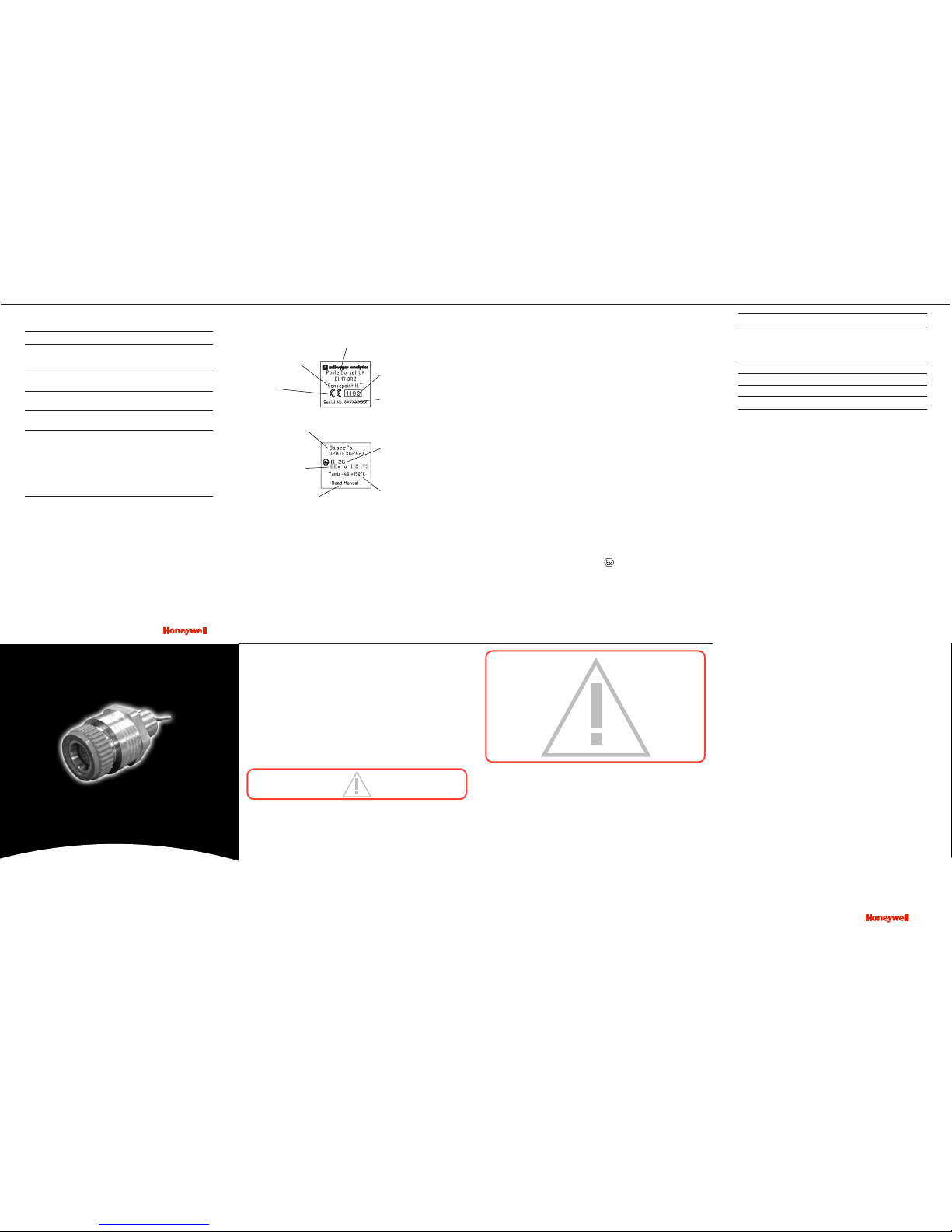
The followi ng BASEEFA certifica tion information is im printed on adjacent
faces in two separate blocks on t he hexagonal part of the sensor body.
CE mark
- conforms to all
applicable European
directives
Manufacturer’s
trademark & address
Identification number
of ATEX notified body
Product name
Year of manufacture/
serial number
Certification number
Explosion protection
mark and equipment
group & category
Certified ambient
temperature range
Certification
code
Caution
6. FAULT FINDING
2. SAFETY
WARNINGS
1. This unit is int ended f or use at a n ormal, or red uced, l evels o f
atmosphe ric oxygen and press ure only, i .e. less th an 21% oxyg en
and less th an 1 .1 b ar. Oxyg en d eficient a tmospheres (less than
10%V/V) may suppr ess the sens or output.
2. Refer to local or n ational reg ulations rel ative t o insta llation at t he
site. Fo r Europe see EN50 073 and EN60 079-14.
3. Operators shou ld be fully awa re of the a ction to be tak en if the gas
concentr ation exceed s the alarm l evel.
4. Installati on should consider not on ly the best placing for gas lea kage
related to p otential l eak points , gas ch aracteristic s and ve ntilation,
but als o where the pot ential of me chanical dam age is mini mized or
avoided .
5. Only asses sed for ATEX for igni tion hazards .
CAUTIONS
1. Atmospheres above 100% LEL may suppress the sensor reading.
2. Do not modify or alter the sensor construction as essential safety
requirements may be invalidated.
3. Install using suitably approved and certified Exe or Exd high temperature
junction box, connectors and glands.
4. Dispose of in accordance with local disposal regulations.
Ma terials used - S tainless Ste el.
The follow ing table provide s a list of possible fa ults related to the s ensor
together wit h possible ca uses and rem edies.
ydemeR/esuaCtluaF
Sensor reads non zero Gas could be present, ensure
all the time there is no combust ible gas in the
atmosphere.
Sensor reads non zero Adjust the control syste m zero
when no gas is pres ent se tting.
Sensor reads low w hen Adjust the con trol system span
gas is applied setting.
Sensor reads high whe n Adjust the control sy stem span
gas is applied setting.
Sensor reads zero w hen 1. C heck the wiring.
gas is applied 2. Check that the pro tective disc
has been removed fr om the
filter housing.
3. Check that the filter is not
dirty/obstructed.
4. Replace the sensor if
poisoning is susp ected.
Issue 1 12/2005
H_MAN0622Z_ 2106M0523_EMEA
07-07
© 2007 Honeywell Analytics
11187
Find out more
Contact Honeywell Analytics:
www.honeywellanalytics.com
Europe, Middle East, Africa
Life Safety Distribution AG
Wilstrasse 11-U11
CH-8610 Uster
Switzerland
Tel: +41 (0)44 943 4300
Fax: +41 (0)44 943 4398
gasdetection@honeywell.com
Americas
Honeywell Analytics Distribution, Inc.
400 Sawgrass Corporate Pkwy
Suite 230
Sunrise, FL 33325
USA
Tel: +1 954 514 2700
Toll free: +1 800 538 0363
Fax: +1 954 514 2784
detectgas@honeywell.com
www.honeywell.com
Technical Services
ha.global.service@honeywell.com
Asia Pacific
Honeywell Analytics Asia Pacific
#508, Kolon Science Valley (1)
187-10 Guro-Dong, Guro-Gu
Seoul, 152-050
Korea
Tel: +82 (0)2 2025 0307
Fax: +82 (0)2 2025 0329
analytics.ap@honeywell.com
Please Note:
While every effort has been made to ensure
accuracy in this publication, no responsibility can
be accepted for errors or omissions. Data may
change, as well as legislation, and you are strongly
advised to obtain copies of the most recently
issued regulations, standards, and guidelines.
This publication is not intended to form the basis
of a contract.
3
5. MAINTENANCE
4 5
CALIBRATION
Table 2 Meter Set tings
* Calibration * Rating of Gas to be Detecte d
Gas
8* 7* 6 * 5* 4* 3* 2* 1*
8* 50 62 76 95 - - - -
7* 40 50 61 76 96 - - -
6* 33 41 50 62 78 98 - -
5* 26 33 40 50 63 79 100 -
4* 21 26 32 40 50 63 80 -
3* - 21 26 32 40 50 64 81
2* - - - 25 31 39 50 64
1* - - - - 25 31 39 50
Note: These settings must only be used with a calibration gas
concentration of 50% LEL. All data at standard temperature and
pressure.
Example
1. Th e target gas to b e detected is B utane.
The calibration gas available is Methane (50% LEL).
2. Look up the star rat ing for each gas from Table 1:
Butane = 4* Methane = 6*
3. Check the meter settings for 50% LEL calibration gas from Table 2.
The reading is 78%.
4. The control card shou ld therefore be set to 78%.
This gives an accurate reading for Butane, using 50% LEL Methan e
as a cal ibration gas .
Table 3 Meter Mul tiplication F actors
Unit calibrated Unit used to detect
to detect
8* 7* 6* 5* 4* 3* 2* 1*
8* 1.00 1.24 1 .52 1.8 9 2.37 2.98 3.78 4.83
7* 0.81 1.00 1 .23 1.5 3 1.92 2.40 3.05 3.90
6* 0.66 0.81 1 .00 1.2 4 1.56 1.96 2.49 3.17
5* 0.53 0.66 0 .80 1.0 0 1.25 1.58 2.00 2.55
4* 0.42 0.52 0 .64 0.8 0 1.00 1.26 1.60 2.03
3* 0.34 0.42 0 .51 0.6 4 0.80 1.00 1.27 1.62
2* 0.26 0.33 0 .40 0.5 0 0.63 0.79 1.00 1.28
1* 0.21 0.26 0 .32 0.3 9 0.49 0.62 0.78 1.00
CALIBRATION
The Sensepoi nt HT Comb ustible Gas Sensor must be fitted into a
suitably ap proved Exe or Ex d high tem perature ju nction box fitt ed with
an approved cable gland for ex ternal w iring. T he s ensor r equires a
200mA curr ent supply, nomi nal 3V, derived fr om a suitable contr ol card.
Only a q ualified inst allation eng ineer should inst all the sens or.
Install the s ensor in a loc ation free fr om direct heat sou rces and fit it so
that it e ither poi nts down wards or horizontally . It is n ot recomm ended
that the senso r po ints upwards. See the Sen sepoint Gas Sensor s
Technica l Handbook f or installat ion in force d air condit ions.
1. Isola teall associated power supplies and ensure that they remain
OFF during the installation procedure. Ensure a gas free
atmospher e.
2. In stall the high temp erature junc tion box.
See the manufacturer’s instructions.
3. Re move the junct ion box lid.
4. Fi t the Sensepoi nt HT sensor t o the junctio n box.
Ensure that the junction box thread and the sensor thread are
compatible. Push the sensor wires through the cable entry in the
junction box and screw the sensor body firmly home into the entry.
Lock the sensor in place with a suitable lock-nut.
5. Co nnect the sens or wiring to the j unction box te rminal strip .
See the subsequent wiring diagram. Use multicore cable, three wire
minimum, of conductor size 2.5mm
2
max.
6. Fi t a suitable gla nd to the box, s ecure the cont rol system cabl e
and conn ect the field w iring to the term inal strip.
See the subs equent wirin g diagram.
7. Re fit the junctio n box lid.
8. Un screw th e filter h ousing f rom the sensor body and rem ove
the filte r from the filt er housing.
Discard the filter housing with protective disc. The filter housing
material cannot withstand high temperatures.
3. INSTALLATION
Sensors sho uld be ca librated at co ncentrations rep resentative of tho se
to be measured . It is al ways recommende d tha t Se nsepoint HT is
calibrat ed with t he target gas i t is to dete ct. If th is is no t possible, th en
cross ca libration can be used .
For ca libration in fast fl ow conditi ons see t he Sensepo int Gas S ensors
Technica l Handbook.
Prior to calibra tion, allow the sensor to warm up for approxim ately
10 minut es. Re-calibra tion should only be at tempted by qualifi ed service
personn el.
1. Ze ro the contro l system with no g as present on the s ensor.
If combustible gas is suspected to be in the vicinity of Sensepoint HT
flow clean air over the sensor using a flow housing (see below).
2. Fi ta flo wh ousing and connect a cyli nder of either air, for a zero,
or a known concentrat ion of gas in a ir, at approxi mately th e
alarm po int (e.g. 50% LEL) , to the flow ho using.
3. P ass the gas throu gh the flow h ousing a t a flow rat e of
approxim ately 1 litre to 1. 5 litre/min.
4. Al low the sensor to st abilise.
5. Wh en gassing wi th air, adjus t the control card to in dicate zero.
6. Fo r span, the c ontrol card should be adjusted to ind icate t he
concentr ation of the t arget gas bei ng applied.
Remove the flow housing and the gas supply.
Cross Cal ibration Pro cedure
When cali brating the Sen sepoint HT sens or with a gas whic h is different
to the gas/vapour to be detected, the following cross calib ration procedure
should b e followed.
Table 1 lists gases accordin gto the rea ction they produce at the detector.
An eigh t star (8*) ga s produces the high est output whil e a one st ar (1*)
gas produces the lo west o utput. (These are not applic able at p pm
levels.)
4. CALIBRATION
7 8 9 10
6
INSTALLATION
CALIBRATION
To calibrat eth eS ensepoint HT sensor car ry out the following proce dure:
1. Ob tain the star r ating f or both the tes t gas an d the g as to be
detected from Tabl e 1 .
2. Us e the v alues in Table 2 to ob tain the r equired m eter sett ing
when a 5 0% LEL test ga s is applied t o the detecto r.
If a sensor is to be used to detect a gas other than that for which it
was calibrated, the required correction factor may be obtained from
Table 3 . The meter reading should be multiplied by this number in
order to obtain the true gas concentration.
Important Notes:
1. Since combustible sensors require oxygen for correct operation,
a mixture of gas in air should be used for calibration purposes.
2. Assuming an average sensor performance, the sensitivity
information in Tables 1 to 3 is normally accurate to ± 20%.
Table 1 Star Rating o f Gases
Gas StarRat ing Gas Star Rati ng
Acetone 4* Hexane 3*
Ammonia 7* Hydrog en 6*
Benzene 3* Methane 6*
Butane 4* Octane 3*
Diethyl ether 4* Propan-2-ol 4*
Ethane 6* Propane 5*
Ethanol 5* Styre ne 2*
Ethyl acetate 3* Tetra hydrafuran 4*
Ethylene 5* Xylene 2*
Sensitive (S)
Non-Sensitive (NS)
Common
Earth
Brown
Blue
White
Green
dleifmetsyslortnoCgniriwrosneS
wiring
Note: Inaddition to the sensor's integral earth conductor, earth
equipotential bonding may be maintained via the sensor rear
mounting thread if required.
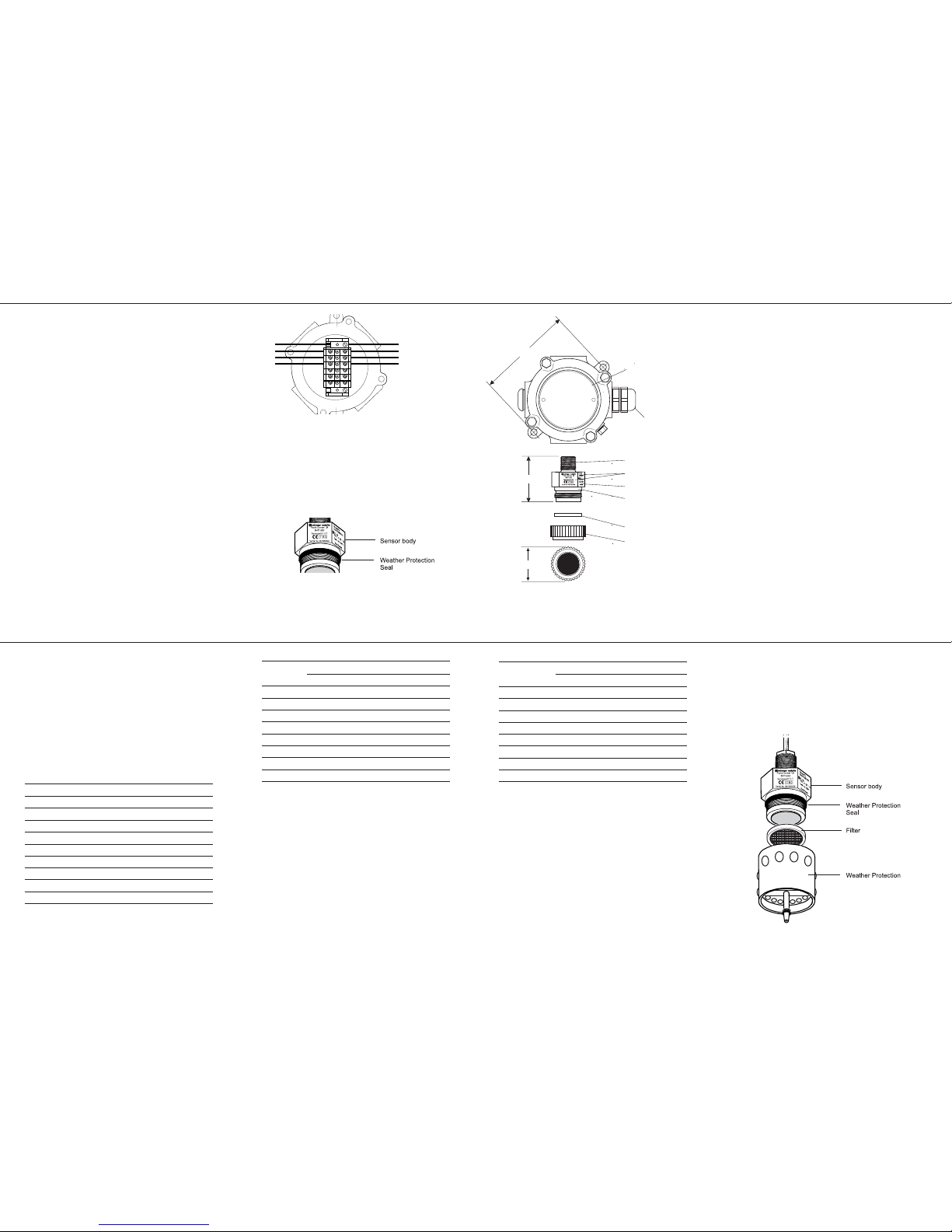
9. If the sens or is install ed:
• ind oors - discar d the filter.
• out doors - fi t the previously removed filter (if required) to
the Hig h Tem pera ture We ather Pr otec tion acc esso ry
(Part No : 00780-A-007 6) and fit the a ccessory to th e sensor.
Fit the seal supplied with the Weather Protection accessory to
the sensor body. Screw the accessory firmly onto the sensor until
it seats against the sensor body hexagon.
10. Pow er-up the syst em and check for c orrect operat ion.
INSTALLATION
High Temperature
Junction Box
Exe/Exd gland
Threads available:
M20, M25, 3/4 NPT
38mm across flats
Sensepoint
Combustible
Gas Sensor 0-100%LEL
Filter
Filter Housing
High
Temperature
Certification data (on
adjacent faces)
58mm
42mm
125mm
Only a qu alified insta llation engin eer should se rvice the sen sor. Ensure
power is off befo re carrying o ut any mainte nance proced ures.
The only maintena nce required is sensor replacem ent and filter changing
(if fi tted to an a ccessory). To re place the c omplete s ensor refe r to th e
Sensepoi nt Gas Sen sors T echnical Handbook . To replac e the filte r
carry ou t the followi ng procedure:
1. Re move the High T emperature We ather Protecti on accessory.
2. Re move the old fi lter and repla ce with a fre sh filter.
3. Re place the Weat her Protectio n accessory.
Ensure the Weather Protection seal is in place. Screw the accessory
firmly onto the sensor until it seats against the sensor body hexagon.
 Loading...