

Page 1
Gas Detection
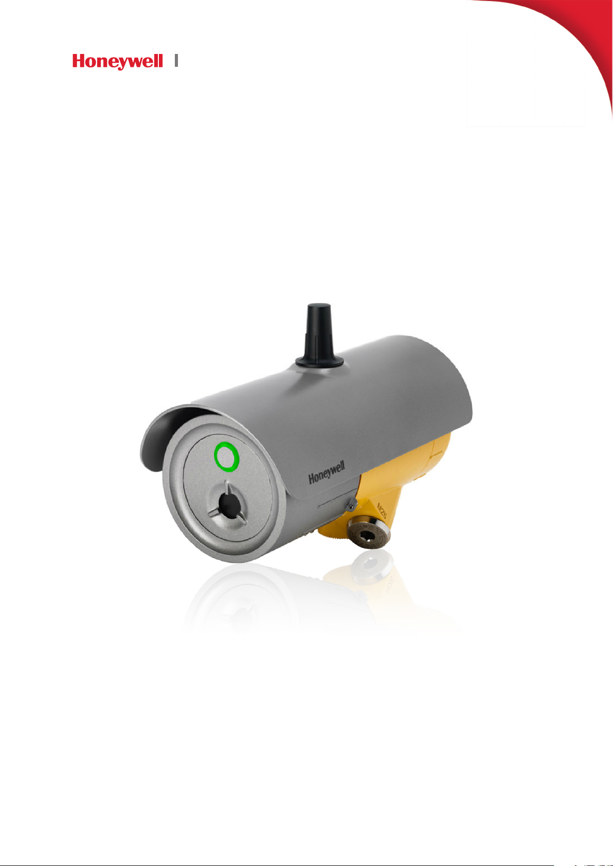
SEARCHZONE SONIK
Technical Manual
Page 2

1 Preface
1.1Introduction
Searchzone Sonik™ is a hazardous area certified advanced ultrasonic gas leak detector for detecting pressurized gas leaks. It provides
local visual status indication as well as 420 mA with HART® and Modbus® outputs as standard. It has a Bluetooth® interface for
configuration and maintenance using the Searchzone Sonik App on a suitable Bluetooth enabled smartphone or other suitable Android
device (mobile device).
The Searchzone Sonik detector is ATEX and IECEx approved for use in either Zone 1 (gas) or Zone 21 (dust) hazardous areas as well as
being cULus approved for use in Class I Division 1 or Class II Division 1 locations. See Certification and Approvals section of this manual
for a list of certificates.
The Searchzone Sonik detector is available in painted Stainless Steel. It has two cable entries for easy wiring with either M25 or
3/4” NPT cable entries, dependent on the version.
1.2Disclaimer
The Searchzone Sonik detector is designed to detect an airborne acoustic ultrasonic signature produced by escaping high pressure gas.
The detector is not designed to identify the presence of any particular type of gas. It will detect the dangerous release of high pressure
gas, whether toxic or flammable for the purpose of protecting people, plant and the environment. Honeywell shall not be liable to pay
for any gas leak investigation or service call carried out or arranged in response to an alarm. Honeywell Analytics Limited can take no
responsibility for installation and/or use of its equipment if this is not done in accordance with the appropriate issue and/or amendment
of the manual. Please note that product designs may change from time to time and the images in this manual should only be used as a
guide.
21 Preface
1.3Scope
This user manual describes how to install the Searchzone Sonik detector and how to commission and operate it in order to ensure
optimal performance.
1.4How to Use This Manual
The manual is structured to cover the instrument, installation (mechanical and electrical), set-up and commissioning, operating and
maintenance. This manual is available in PDF format .
1.5Copyright & Trademarks
This document is the copyright of Honeywell.
Searchzone Sonik is a Honeywell trademark.
1.6Patents
The Searchzone Sonik advanced ultrasonic gas leak detector uses patented sensing technology. Focus Mode, an operating mode of
Searchzone Sonik is patent pending.
1.7Revision History
Revision Comment Date
Issue 1 A05126 November 2018
Searchzone Sonik − Technical ManualPN 2331M1220 Issue 1 11/2018
Page 3

Table of Contents
1 Preface 2
1.1Introduction 2
1.2Disclaimer 2
1.3Scope 2
1.4How to Use This Manual 2
1.5Copyright & Trademarks 2
1.6Patents 2
1.7Revision History 2
2 Safety and Information 8
2.1Warnings and Cautions 8
2.2Important Information 9
2.3Organisational Measures for Functional Safety 9
31 Preface
3 Overview and Introduction 10
3.1Description of Product 10
3.2Description of Function 10
3.3Applications 10
3.4Sensor Technology Description 10
3.5Environmental Factors 10
3.5.1 Introduction to Background Noise and Interference 10
3.6Range and Field of Coverage 11
3.6.1 Standard Mode 11
3.6.2 Focus Mode 12
3.7Description of Gas Leak Detection Using Ultrasound 12
3.8Mounting Accessories and Flexibility 12
3.9Commissioning and Maintenance Tools 13
3.10Available Accessories 14
4 Siting Considerations 15
4.1Safety Case Framework 15
4.2Siting the Detector 15
4.2.1 Mounting Position 16
4.2.2 Mounting Angle 16
4.3Accidental Impact 16
4.4Change in Site Infrastructure 16
4.5Transient Background Noise 16
4.6Location Survey 16
Searchzone Sonik − Technical ManualPN 2331M1220 Issue 1 11/2018
Page 4

4.7Bluetooth Considerations 17
5 Mechanical Installation 18
5.1Visual Check after Transportation 18
5.2Description 18
5.3Main Parts 19
5.4Mounting Searchzone Sonik 20
5.5Pole Mount Installation 22
5.6Wall Mount Installation 24
5.7Assemble Cable Glands 25
5.8Connect Cable Glands to the Searchzone Sonik 25
5.9Detector Attachment 26
5.9.1 Detector removal 26
5.10Connect Wires to PCB Terminals 28
5.11Sunshade Installation 30
41 Preface
6 Electrical Installation 31
6.1Power Supply Requirements 31
6.1.1 Internal Battery Cell 31
6.2420 mA Current Loop 31
6.3Relays 32
6.4Connections / Wiring Diagram 32
6.4.1 Terminal Wiring Description 33
6.4.2 Searchzone Sonik Connection for mA loop Configuration as Current Source 34
6.4.3 Searchzone Sonik Connection for mA Loop Configuration as Current Sink 35
6.4.4 Searchzone Sonik Connection for mA Loop Configuration as Isolated Output 35
6.5Cabling Recommendations 35
6.6Earthing Recommendations 36
6.7Modbus 36
7 Commissioning and Configuration 37
7.1First Time Switch On 37
7.1.1 Pre-power Check 37
7.2Operating Function Verification 37
7.3Communication 37
7.3.1 Bluetooth® 37
7.4Settings and Configuration 37
7.5Delay Time 38
7.6Background Noise Rejection 38
7.7Performance Verification 38
Searchzone Sonik − Technical ManualPN 2331M1220 Issue 1 11/2018
Page 5

8 Operation 39
8.1Operation 39
8.2Status Signalling 39
8.2.1 Visual Status Indicator 39
8.2.2 mA Loop Status 40
8.2.3 Relay Signalling 40
8.3Normal Operation 40
8.4Operation During Fault 40
8.5Operation During Alarm 41
8.5.1 Pre-alarm 41
8.5.2 Alarm 41
8.5.3 Overload 41
9 Mobile App 42
9.1General User Access 42
51 Preface
9.2Terminology 42
9.3Communications 43
9.3.1 Company Account Management 43
9.3.2 Creating a New Company Account 43
9.4Connecting to Detectors 47
9.4.1 How to Connect to a Searchzone Sonik Detector 47
9.4.2 Making an Ad Hoc Connection to the Detector 49
9.5Detector Overview 50
9.5.1 Detector Status 50
9.5.2 Detector Inhibit 51
9.6Detector Alarm History 52
9.7Detector Maintenance 53
9.7.1 Event Log 53
9.7.2 Set Maintenance Flag 54
9.7.3 Output Test 55
9.7.4 Diagnostics 56
9.8Detector Settings 58
9.8.1 Firmware Version 59
9.8.2 Background Levels 60
9.8.3 Editing Detector Settings 61
9.9How to Change Application Settings 64
9.9.1 Detector Registrations 64
9.10User Management 65
Searchzone Sonik − Technical ManualPN 2331M1220 Issue 1 11/2018
Page 6

10 Communications 67
10.1HART® 67
10.1.1 Searchzone Sonik HART Interface 67
10.2Menu Structure 68
10.3Commissioning using HART Communications 72
10.3.1 User Configuration 73
10.3.2 Configure Warning, Inhibit and Over-range Signal Levels 73
10.3.3 Configure Device Identification Information 74
10.3.4 Test 4-20 mA Loop Integrity 75
10.3.5 Configure Internal Alarm Threshold 75
10.3.6 Clear Alarm Latch 75
10.4Maintenance using HART Communications 76
10.4.1 Inspection 76
10.4.2 Proof Test (Gas Leak Challenge) 77
61 Preface
10.4.3 Investigation of Faults or Warnings 77
10.5Modbus 78
10.5.1 Programming the Host 78
10.5.2 Addressing Conventions and Register Values 78
10.5.3 Modbus Cables 78
10.5.4 Modbus Electrical Connections 79
10.5.5 Modbus Termination Resistor 79
10.5.6 Modbus Multi-Drop Mode 79
10.5.7 Modbus Protocol 79
10.5.8 Modbus Registers 80
11 Maintenance 84
11.1Inspection and Cleaning 84
11.2Periodic Proof Test using a Canister of Compressed Air 84
11.3Suggested Maintenance Schedule 84
11.4Response to Fault 85
11.5Product Life Expectancy 85
12 Problem Solving 86
12.1Introduction 86
12.2Problem Solving 87
13 Certification and Approvals 89
13.1Hazardous Locations 89
13.2ATEX Certification 89
Searchzone Sonik − Technical ManualPN 2331M1220 Issue 1 11/2018
Page 7

13.3IECEx Certification 89
13.4CSA Certification 90
13.5cULus Certification 90
13.6Labelling 91
13.7EU Declaration of Conformity 91
13.8RoHS 91
13.9China RoHS 92
13.10WEEE 92
13.11EMC 92
13.12RED 92
13.13REACH 92
13.14FCC 92
13.15IC 93
13.16Export Compliance Classification 93
71 Preface
13.17Wireless Approvals 93
13.18Bluetooth® 93
14 Ordering Information 94
15 Specifications 95
15.1Short Form Table 95
Searchzone Sonik − Technical ManualPN 2331M1220 Issue 1 11/2018
Page 8
2 Safety and Information
2.1Warnings and Cautions
WARNING
1. Installation must be in accordance with the recognized standards of the appropriate authority in the
country concerned. For Europe see EN 6007914 and EN 60079292.
2. Installation, operation and maintenance of the unit must meet requirements on safety and operation in
hazardous areas.
3. The equipment is NOT intended to be mounted onto surfaces which may act as sources of heating or
cooling.
4. Do NOT operate the unit outside the temperature range stated in the Specification section.
5. Do NOT open the front enclosure. Doing so will invalidate the warranty.
6. Operators should be fully aware of the action to be taken in the event of an alarm.
7. Do NOT modify or alter the construction of the product as essential safety and certification
requirements may be invalidated.
8. Installation, set-up and maintenance must be conducted only by trained personnel. Refer to the
manual at all times.
9. Access to the interior of the product, when carrying out any work, must be conducted only by trained
personnel.
10. In order to maintain electrical safety, the unit must NOT be operated in atmospheres of more than
21% oxygen.
11. The plastic transport cap supplied must be replaced with suitably certified closers (such as glands or
stopping plugs) prior to commissioning. Failure to do so presents a potential source of ignition. One
certified stopping plug is supplied as standard.
12. Do NOT rely on the local visual indicator for safety related purposes.
82 Safety and Information
CAUTION
If the time in which a user logs in to the Searchzone Sonik App in the online mode exceeds 1 year,
it will be necessary to establish an Internet connection to the mobile device and log in to the App in
order to refresh the detector’s security certificate.
Items of Disposal
Enclosure Painted 316 Grade Stainless Steel
Standard Adjustable
Mounting Bracket
Sunshade Plastic / Stainless Steel (optional)
This symbol indicates that this product and/or parts of the product may not be treated as
household or municipal waste. Waste electrical products (end of life) should be recovered/
recycled where suitable specialist WEEE disposal facilities exist. For more information about
recycling of this product, contact your local authority, our agent/distributor or the manufacturer.
Stainless Steel
Searchzone Sonik − Technical ManualPN 2331M1220 Issue 1 11/2018
Page 9
2.2Important Information
This manual is for use with the Honeywell Searchzone Sonik advanced ultrasonic gas leak detector only.
Honeywell Analytics can take no responsibility for installation and/or use of its equipment if not done so in accordance with the
appropriate issue and/or amendment of this Manual.
The reader of this Manual should ensure that it is appropriate in all details for the exact equipment to be installed and/or operated. If in
doubt, contact Honeywell Analytics for advice.
The following types of notices are used throughout this Manual.
WARNING
Identifies a hazardous or unsafe practice which could result in severe injury or death to personnel.
CAUTION
Identifies a hazardous or unsafe practice which could result in minor injury to personnel, or product or
property damage.
92 Safety and Information
Note
Identifies useful/additional information.
Every effort has been made to ensure the accuracy of this document, however, Honeywell Analytics can assume no responsibility for any
errors or omissions in this document or their consequences.
Honeywell Analytics would greatly appreciate being informed of any errors or omissions that may be found in the content of this
document.
For information not covered in this document, or if there is a requirement to send comments/corrections about this document, please
contact Honeywell Analytics using the contact details given on the back page.
Honeywell Analytics reserve the right to change or revise the information supplied in this document without notice and without
obligation to notify any person or organization of such revision or change. If information is required that does not appear in this
document, contact the local distributor/agent or Honeywell Analytics.
2.3Organisational Measures for Functional Safety
Refer to the Searchzone Sonik Safety Manual for more information.
Searchzone Sonik − Technical ManualPN 2331M1220 Issue 1 11/2018
Page 10

103 Overview and Introduction
3 Overview and Introduction
3.1Description of Product
The Searchzone Sonik is an advanced ultrasonic gas leak detector for use in hazardous areas. It detects high pressure gas leaks within
the protection area, in order to provide an early alert to a hazard. While the Searchzone Sonik does not indicate the type of gas, it will
respond to any high pressure gas leak within the coverage area and so will protect against the release of dangerous gases, whether they
be toxic or flammable.
With conventional gas detectors, the escaping gas has to reach the detection point or line between a transmitter/receiver pair. The
Searchzone Sonik ultrasonic gas leak detector recognizes sound emitted by the leak from a distance, without the released gas having to
reach the detector.
3.2Description of Function
The Searchzone Sonik detects pressurised gas leaks by sensing the airborne acoustic ultrasonic sound pressure wave and signature
produced by the escaping gas. The detection method uses a robust patented piezo-based sensor which will function in extreme weather
conditions, on and offshore. With no moving parts and no sensor cover required, the Searchzone Sonik can withstand adverse conditions
including pressure wash-down. The detector does not require field calibration, only periodic bump testing, which can be accomplished
from ground level. Interfacing for set-up, commissioning and maintenance can be achieved wirelessly using the Searchzone Sonik App,
running on a suitable Bluetooth-enabled mobile device.
3.3Applications
The Searchzone Sonik detector is ideal for detecting gas leaks from units such as metering skids, compressors, pumps, valves and
pipework flanges in complex and congested distribution, process and transmission systems.
3.4Sensor Technology Description
The Searchzone Sonik detector employs an advanced ultrasonic sensor module that is robust and reliable even in harsh environmental
and operational conditions. The sensor module has a very long life in these adverse conditions and does not require field calibration.
The sensor detects the ultrasonic sound pressure waves, which are longitudinal vibrations that propagate through the air. Upon entering
the sensor structure, the sound pressure waves create a voltage across the transducer, which is then amplified and processed using
advanced detection algorithms. The patented piezo-based ultrasonic sensor module is robust with minimal failure modes.
3.5Environmental Factors
The leak detection range is limited by the atmospheric absorption of the ultrasound. This absorption increases with frequency. The
Searchzone Sonik will detect specified gas leaks typically up to 20m in all conditions. Background noise levels also have an effect
on the detection range. Process equipment which generates ultrasonic noise will need to be considered when setting the detection
thresholds of the detector, which can cater for high, medium and low levels of background noise. The detection range of the detector will
be maximal at lower levels of background ultrasonic noise. Typical sources of background noise include rotating machinery, clanking
chains, steam whistles and other steam release mechanisms, air horns as well as intentional gas releases.
Note
Ice build-up on the face of the sensor will cause an increase in sensitivity, which may lead to an increase in nuisance alarms. When
mounting in locations where ice build-up is likely, take necessary precautions in protecting the unit against such build-up and/or setting
of alarm levels.
3.5.1Introduction to Background Noise and Interference
The frequency of the noise being produced by the source will also have a bearing on the measurement range since the attenuation
co-efficient of sound in air increases with frequency. This not only affects the sound pattern generated by a gas leak but also that
generated by other sources of ultrasonic noise and they differ. The Searchzone Sonik detection is optimized to detect gas leaks in real
Searchzone Sonik − Technical ManualPN 2331M1220 Issue 1 11/2018
Page 11
113 Overview and Introduction
world conditions. The sound pressure level generated by a high pressure gas leak is dependent upon the pressure, the leak diameter, and
upon the gas density. The Searchzone Sonik detector is designed to detect hazardous high pressure leaks.
As a guide, the following table indicates typical maximum detection ranges that can be achieved for various levels of background
ultrasonic noise.
Detection Threshold Level 64 dB (Low) 74 dB (Mid) 84 dB (High)
Standard Detection Mode 24 m 12 m 7 m
Focus Detection Mode 7 m 5 m 3 m
Note
Due to variances sound level intensity generated across the measured frequency range and angular positioning of the detector.
The above values may vary up to 50%.
The values in the table above were achieved with a methane leak, mass flow rate of 0.1 kg/s at an environment of 20°C, 50 %RH and a
standard atmospheric pressure of 1013 hPA.
Note
The Background Levels feature, available in the Searchzone Sonik mobile App, can be used to validate and check that the current
detector settings are appropriate. Refer to section 9.9 Detector Settings for more information.
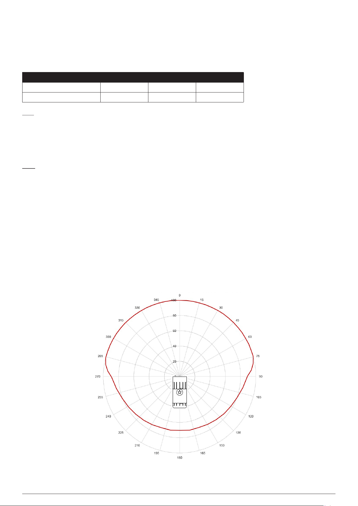
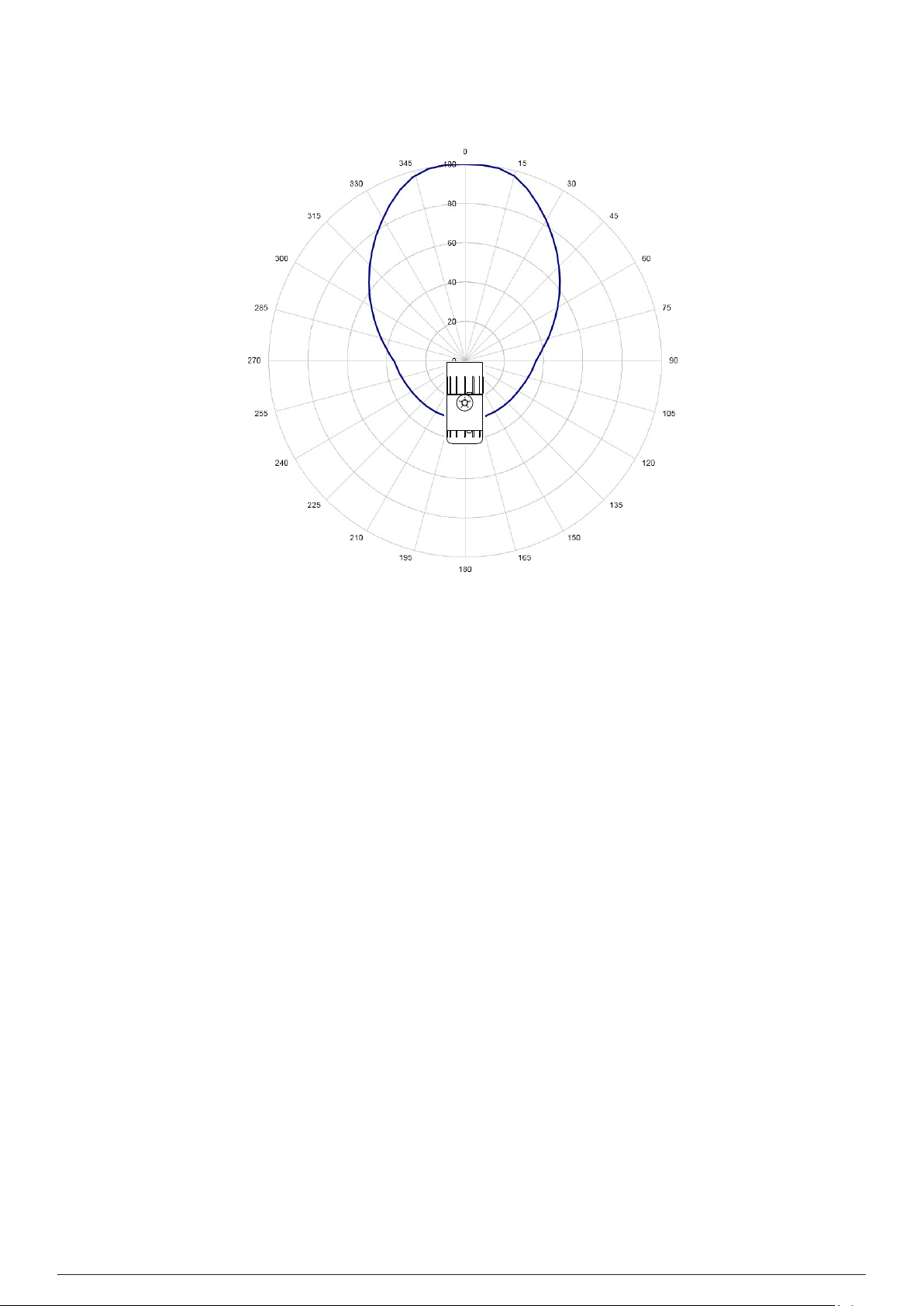
3.6Range and Field of Coverage
The Searchzone Sonik detector has a dynamic range of 40dB to 140 dB giving a detection range of typically 20m on-axis radius
(background noise dependant). The field of detection coverage (FoC) is +/90 degrees in both horizontal and vertical planes measured
on-axis to the face of the detector’s sensor.
The detection algorithms (Standard or Focus) differentiate between leak signatures and typical noise source signatures in both time and
frequency domains. The polar plots in the Figures 3 and 4 below show the typical detection areas for both Standard and Focus modes.
Refer to the table in section 3.5.1 for typical ranges that can be achieved for both Standard Mode and Focus Mode.
3.6.1Standard Mode
Use Standard Mode for larger areas which are subject to lower levels of background noise and where nuisance alarms sources are not
expected.
Figure 3.Angular Field of Coverage in
Standard Mode (% of Range)
Searchzone Sonik − Technical ManualPN 2331M1220 Issue 1 11/2018
Page 12
3.6.2Focus Mode
Use Focus Mode for closer areas which are subject to high levels of background noise and where nuisance alarm sources are expected.
123 Overview and Introduction
Figure 4.Angular Field of Coverage in
Focus Mode (% of Range)
3.7Description of Gas Leak Detection Using Ultrasound
A high pressure gas leak is a broadband continuous phenomenon. This gas leak ultrasound signature is detected in the presence of
other ultrasound noise sources using advanced detection algorithms. The detection algorithms differentiate between leak signatures
and typical noise source signatures in both time and frequency domains.
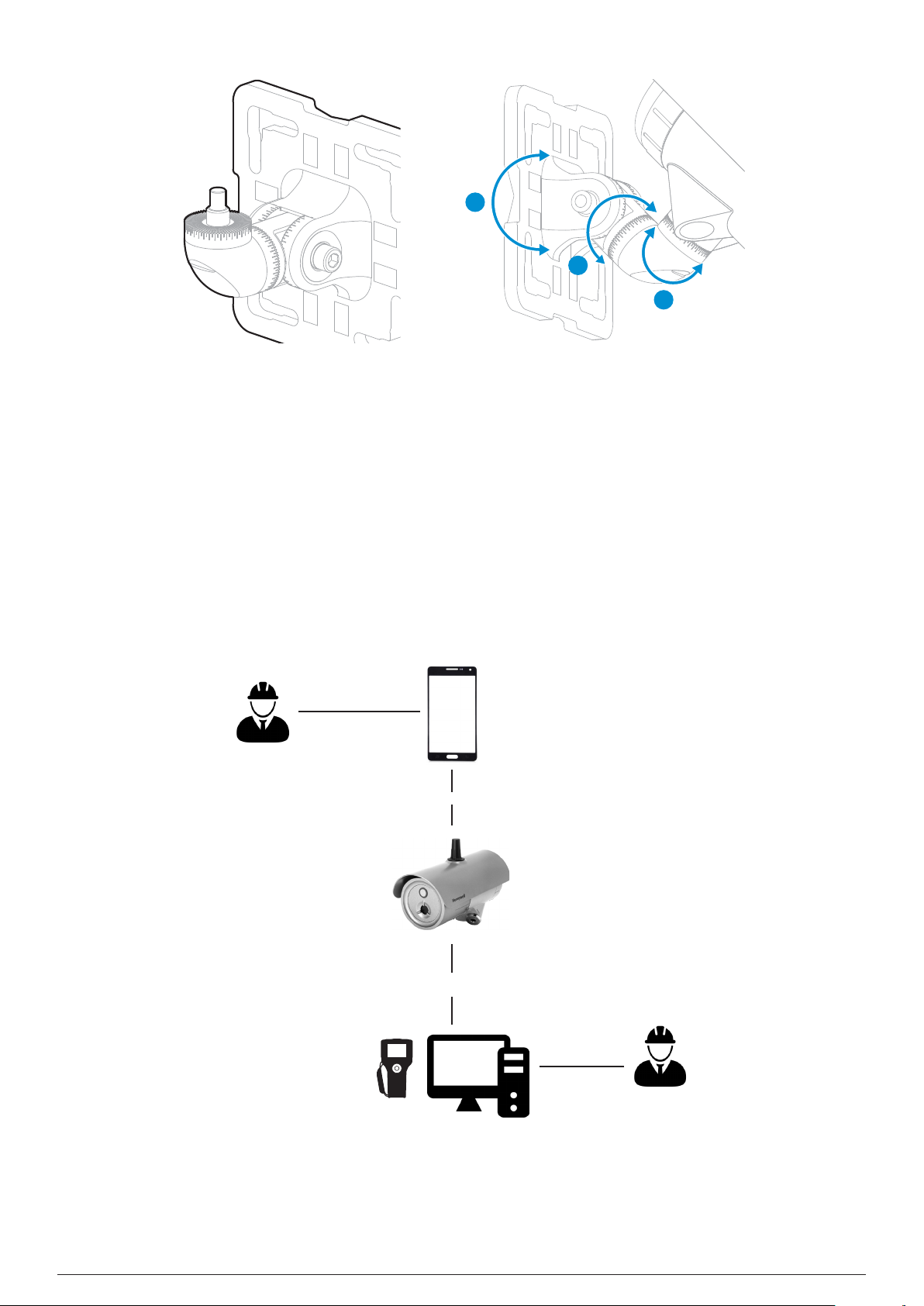
3.8Mounting Accessories and Flexibility
The Searchzone Sonik detector is supplied with the Standard Adjustable Mounting Bracket that can be simply installed prior to the
fitting of a Searchzone Sonik detector. The 3-axis adjustment allows the detector to be aimed precisely and has graduated angles
marked on the adjustments. The Standard Adjustable Mounting Bracket allows simple fixing onto a range of surfaces as well as poles,
struts, plates and other plant infrastructure. It is manufactured from high quality Stainless Steel.
LEGEND:
- Adjusting range in the vertical axis (A) = 0° to 90°
- Adjusting range in the horizontal axis (B) = 45° to +45°
- Adjusting rotational range (C) = 45° to +45°
- Graduated adjustment in 5 degree steps
- Graticule for easy setting
Searchzone Sonik − Technical ManualPN 2331M1220 Issue 1 11/2018
Page 13
133 Overview and Introduction
A
C
B
Figure 5.Standard Adjustable
Figure 6.Adjustment ranges
Mounting Bracket
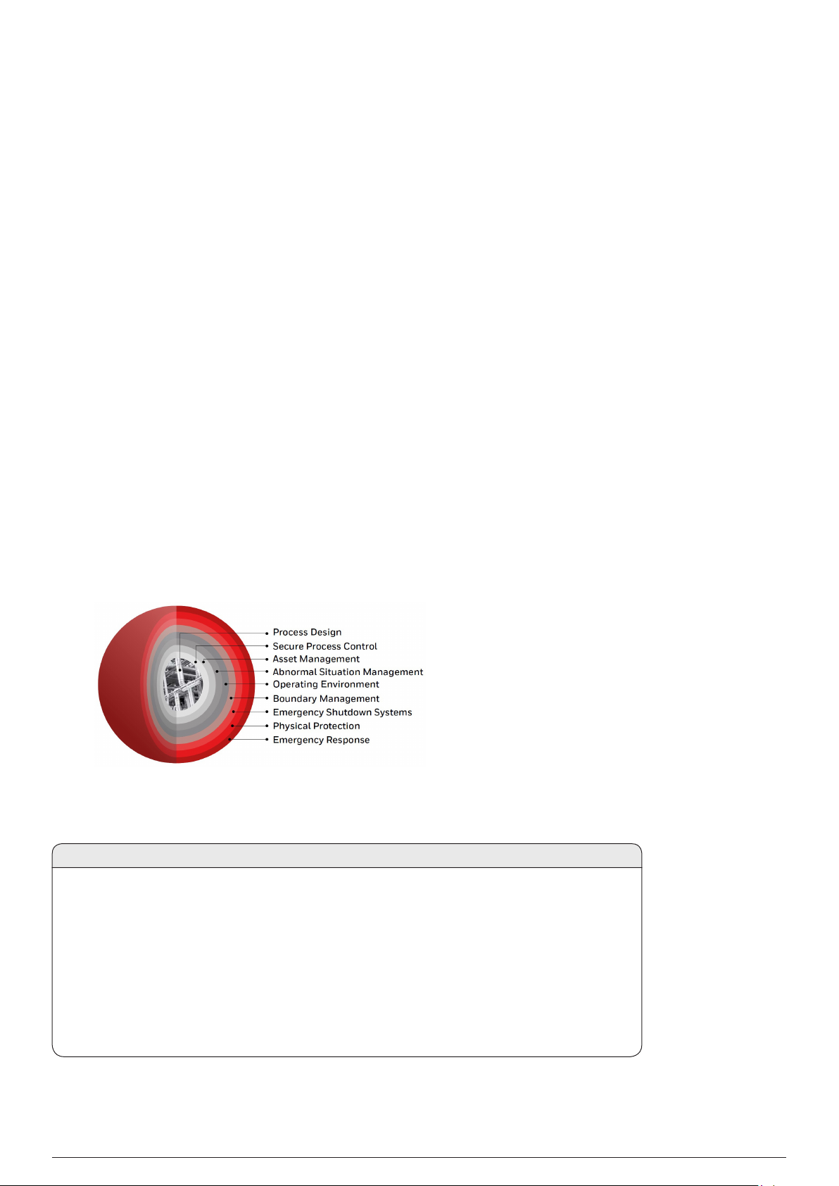
3.9Commissioning and Maintenance Tools
The Searchzone Sonik Mobile App is an Android-based application downloadable from Google Play. It connects via Bluetooth to the
Searchzone Sonik detectors and is the primary tool for installation, commissioning and maintenance.
The HART and Modbus protocols provide additional means of communicating with Searchzone Sonik for the purpose of installation,
commissioning and maintenance.
Searchzone Sonik Mobile App
Installation/
Commissioning
Engineer
Bluetooth
HART
Modbus
Plant Management System
Figure 7.Searchzone Sonik communication diagram
Searchzone Sonik − Technical ManualPN 2331M1220 Issue 1 11/2018
Plant Operator
Page 14

3.10Available Accessories
The Standard Adjustable Mounting Bracket and a Plastic Sunshade are provided as standard. The following items are available as
optional accessories. Refer to the Ordering Information section of this manual for more information:
1. Large Adjustable Mounting Bracket
2. Stainless Steel Sunshade
3. Hazardous Area Mobile Phone
4. Searchzone Sonik App
143 Overview and Introduction
Searchzone Sonik − Technical ManualPN 2331M1220 Issue 1 11/2018
Page 15
154 Siting considerations
4 Siting Considerations
When designing an installation for a Searchzone Sonik detector it is important to give due consideration as to where it is to be located,
what potential sources of problems that may be encountered in the intended location and how the detector is to be mounted.
Users are strongly recommended to consult with experts who are experienced in site mapping and siting of ultrasonic gas leak detectors
when determining final positioning.
4.1Safety Case Framework
In compliance with IEC 61508, IEC 61511 and EEMUA recommendations, the Safety Case Framework is used as a method of
reducing risks at hazardous installations to acceptable levels. The framework is based on the concept of Layers of Protection which is
widely recognized by the process industry and clearly defined in industry safety standards.
Considering the application of all types of the protection layers − some layers are preventative (e.g., emergency shut down), while
some are there to mitigate the impact of an incident should it occur (e.g., fire and gas protective systems or plant emergency response
systems). Other layers of protection can counter occurrence of incidents in the first place (e.g., plant and physical asset protection,
constraint and boundary management, operator training, and asset management); while others can provide detection and alerting, and
associated guidance (e.g., operator alarms, early event detection, and integrated operator procedures). Layers can either be automated,
such as emergency shut down (ESD) equipment, or require human interaction such as operator responses to process alarms. Some
layers offer easily quantifiable risk-reduction benefits but require that the risks all be identified before. And still others are less tangible
and offer subtler benefits.
An Advanced Ultrasonic Gas Leak Detector will generally be used as part of a Gas Detection and Mitigation layer. Ultrasonic gas leak
detectors complement point and open path gas detectors as they detect the gas leak by sensing the sound pressure level created by a
high pressure gas leak. Ultrasonic gas leak detectors are affected by environmental conditions but not significantly by wind.
4.2Siting the Detector
CAUTION
1. Do NOT install in areas where detector can be struck by falling objects.
2. Do NOT site the detector where maintenance may impact, misalign or damage the detector.
3. Avoid installing on a vibrating infrastructure.
4. Install the detector a minimum of 1 m away from potential source of gas leak. Point the detector
30 degrees away from the potential source of gas leak.
5. A detector installed a minimum of 3 m away from a potential source of gas leak may be aimed directly
at it.
6. Do NOT operate the detector outside of the allowed temperature range. Refer to the Specification
section of this manual for more information.
Searchzone Sonik − Technical ManualPN 2331M1220 Issue 1 11/2018
Page 16

4.2.1 Mounting Position
It is recommended that Searchzone Sonik is placed close to the area to be protected to maximise the detection performance. For best
performance, use the following location principles when determining final positioning of the detector:
• Avoid situations were a leak plume is presented directly to the face of the detector. For best results, aim the detector at the potential
leak but at an angle of approximately 30 degrees off axis of the resultant plume.
• When monitoring a pipe containing the pressurized gas, mount the detector so that it ‘looks’ along the pipe.
• Avoid mounting the detector directly next to or over sources of ultrasonic noise e.g. compressor, gearbox, turbine, generator, etc.
• Do not install the detector next to pressurized air lines and fittings.
• Positioning the detector away from sources of unwanted ultrasonic noise will significantly reduce the risk of nuisance alarms.
4.2.2Mounting Angle
It is recommended that Searchzone Sonik is mounted pointing downwards by at least 30 degrees when used outdoors to allow the
sunshade to protect the sensor from the adverse environmental conditions.
4.3Accidental Impact
Situations where there is a significant probability of equipment, personnel or moving objects accidentally impacting Searchzone Sonik
detector should be avoided. If such locations cannot be avoided, measures including increase mechanical protection and warning
notices should be considered.
164 Siting considerations
4.4Change in Site Infrastructure
When there are changes in site infrastructure or configuration, which may introduce new sources of ultrasound, the customer should
review the existing configuration of Searchzone Sonik detectors and decide if it needs to be adapted to suit those changes.
4.5Transient Background Noise
Transient background noise from processes that release gas or steam under pressure (e.g., planned release of gas intended by the
operator) can cause unwanted triggering of an ultrasonic gas leak detector. These can be avoided by setting an alarm delay which is
longer than duration of that process operation.
4.6Location Survey
Points of consideration:
1) Assess the Risk Case
a. What is the risk?
b. What is the anticipated gas leak sound pressure level ?
c. What is the protection method?
d. What is the detection method in case of a leak?
e. How best to mitigate the risk?
2) Assess the environmental conditions before installation
3) Assess the potential sources of background noise in the area
If necessary measure these at the proposed ultrasonic gas leak detector install position
4) Assess the area to be covered by an ultrasonic gas leak detector with respect to:
a. Type of working environment
b. Local sources of ultrasounds
5) Choose an appropriate distance of the detector from the monitored area. Avoid installing the detector at or close to maximum range
to allow higher detection thresholds to be set, reducing the risk of false false alarms. See coverage diagrams specified in Overview
and Introduction section of this manual.
Searchzone Sonik − Technical ManualPN 2331M1220 Issue 1 11/2018
Page 17

174 Siting considerations
6) Choose Standard or Focus Mode with respect to the expected background noise levels and the nature of the risk to be covered.
Refer to the Overview and Introduction section of this manual for more information.
7) Choose the detector’s mounting position and angle, considering
a. Coverage
b. Ease of access
c. The direction of any potential leak. Refer to section 4.2.1 Mounting Position.
8) Ensure that the risk of physical impact, misalignment, or damage of the detector by human factor or uncontrollable events is avoided
4.7Bluetooth Considerations
1. Is use of Bluetooth permitted on the site?
2. Is the mobile device rated for operation in hazardous locations?
3. Is the Searchzone Sonik installed within 20 m from the place where operator will stand?
4. Is there direct visibility ensured between the Searchzone Sonik and the mobile device?
Searchzone Sonik − Technical ManualPN 2331M1220 Issue 1 11/2018
Page 18

5 Mechanical Installation
5.1Visual Check after Transportation
The Searchzone Sonik pack includes:
• The Searchzone Sonik Gas Leak Detector
• Standard Adjustable Mounting Bracket
• Plastic Sunshade
• One certified blanking plug
• Tool Kit
To ensure that the Searchzone Sonik unit was not damaged during transport, perform the following checks:
1. Check the packaging for damage before opening. If the packaging shows signs of tearing, breakage or other damage, immediately
inform the transport company and the supplier. Document the damage in an appropriate way (e.g., photographs).
2. Open the packaging carefully to avoid damaging the contents.
3. Examine the Searchzone Sonik detector for damage. If you find the detector to be damaged in any way, immediately inform the
transport company and the supplier. Document the damage in an appropriate way (e.g., photographs).
4. In the case of damage: a) Leave the detector in the original packaging
b) Do not attempt repair, or operate the detector until the damage claim has been resolved with the supplier.
185 Mechanical Installation
CAUTION
1. Installation, set-up and maintenance must be conducted only by trained and authorized personnel.
2. Do NOT open the front enclosure. The warranty of a unit, whose front enclosure has been opened, is invalidated.
3. Do NOT modify the front enclosure or component parts as this will compromise the hazardous location certification and
invalidate the warranty.
4. Do NOT modify the construction of the detector in any way as this will invalidate the warranty.
5. Open and close the wiring compartment cover with care to avoid deformation.
6. Installation, set-up and maintenance must be conducted only by trained and authorized personnel.
7. Avoid water and dust ingress when opening the wiring compartment to protect the unshielded electronic contacts.
8. Secure the detector when loosening bracket bolts. Unwanted release may cause injury.
9. Check mating surfaces prior to assembly (threads, O-rings). Ensure that they are clean and free of contaminants.
10. Check the O-rings prior to assembly, replace if damaged with genuine parts.
11. The Searchzone Sonik is supplied without cable glands. Ensure that all cable entry threads are sealed with an
appropriate plug to eliminate water ingress and thread damage. At installation, the cable entry transportation plugs
must be removed and replaced with suitable cable glands, thread adapters or blanking plugs to meet local hazardous
location requirements.
12. Check suitability of the blanking plug for its end use on site, ensure it meets local and national regulations.
13. Remove power from the Searchzone Sonik detector while installing wiring. Do NOT install wires or set up wiring with
power applied.
5.2Description
The Standard Adjustable Mounting Bracket enables Searchzone Sonik to be fitted to a wide range of plant infrastructure and then
appropriately aimed to cover the area to be protected. It is manufactured in 316L Stainless Steel.
A Large Adjustable Mounting Bracket is available as option to suit installation on larger diameter poles.
Searchzone Sonik cable entries are 2 x M25 or 2 x ¾” NPT dependent on the version.
The two compartment design means that the sensing electronic module and wiring compartment are separate. There are no set-up
switches within the electronics.
Two pluggable connectors are provided within the wiring compartment. The connectors feature mechanical retention.
Searchzone Sonik − Technical ManualPN 2331M1220 Issue 1 11/2018
Page 19
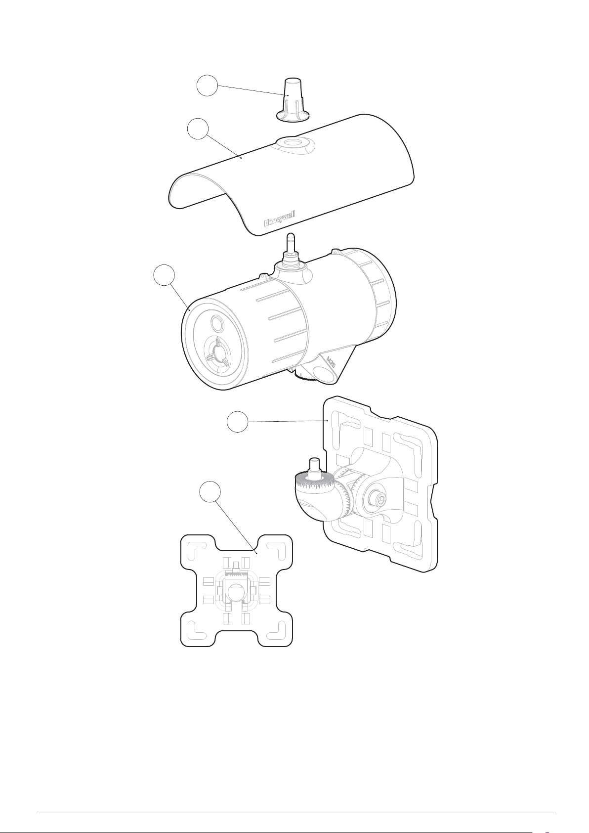
5.3Main Parts
195 Mechanical Installation
4
3
1
2
5
Figure 8.Searchzone Sonik general view
LEGEND:
1. Searchzone Sonik Advanced Gas Leak Detector
2. Standard Adjustable Mounting Bracket to fit on a plate, pole or plant infrastructure
3. Sunshade
4. Antenna cover
5. Large Adjustable Mounting Bracket (optional)
Searchzone Sonik − Technical ManualPN 2331M1220 Issue 1 11/2018
Page 20
5.4Mounting Searchzone Sonik
Searchzone Sonik will normally be mounted at height, typically secured to a pole using the UBolts or Worm Drive Clips supplied in the
Pole Installation Kit (optional).
The supplied Standard Adjustable Mounting Bracket allows mounting on a plate, pole or other plant infrastructure. All bolts are captive
to avoid accidental loss during installation.
CAUTION
IMPORTANT: When tightening the pivot bolts, first, tighten the left-facing horizontal M10 bolt to fix the pivot in
its horizontal position. Second, tighten the right-facing horizontal M10 bolt. Tighten these bolts to a final torque of
30 Nm/22 lb.ft.
205 Mechanical Installation
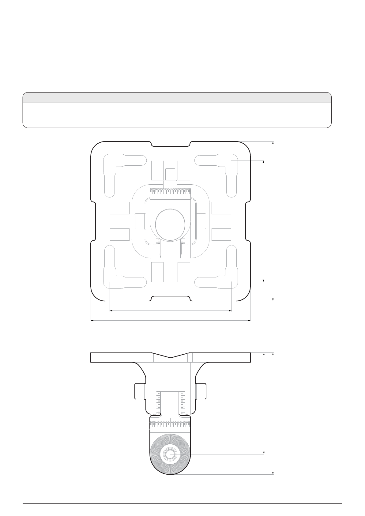
126 mm (4.95")
165 mm (6.5")
165 mm (6.5")
126 mm (4.95")
105 mm (4.15")
Figure 9.Standard Adjustable Mounting Bracket general view and dimensions
Searchzone Sonik − Technical ManualPN 2331M1220 Issue 1 11/2018
126 mm (4.95")
Page 21
215 Mechanical Installation
12
11
13
6 1
2
3
8
8
7
8 8
4 5 6
10
9
7
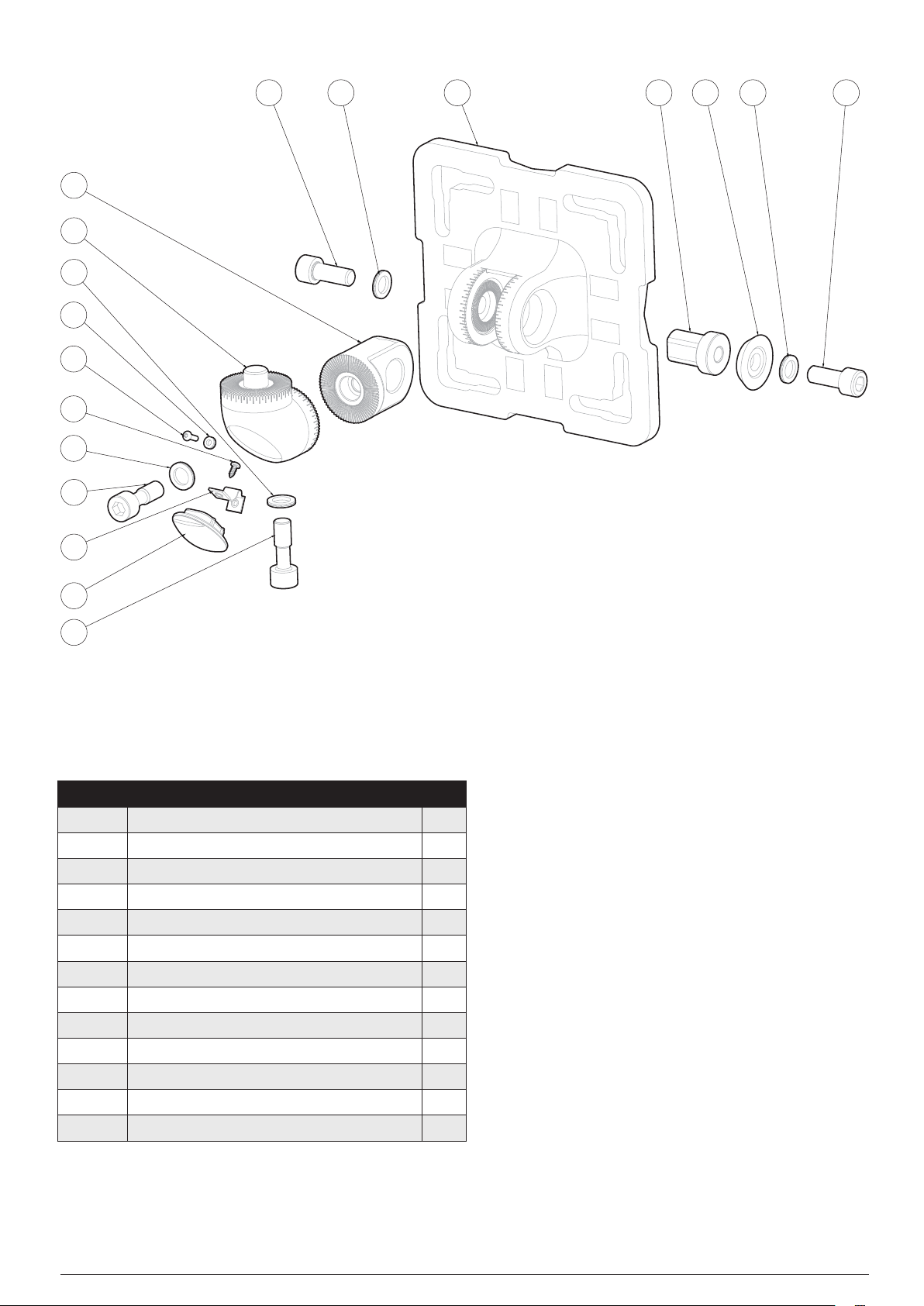
Figure 10.Standard Adjustable Mounting Bracket exploded view
LEGEND:
Position Description Pcs.
1 Standard Adjustable Mounting Bracket flange 1
2 Vertical pivot 1
3 Horizontal pivot 1
4 Keyed insert 1
5 Conical washer 1
6 Bolt M10x25 2
7 Captive Bolt M10x30 2
8 Nord lock washer M10 4
9 Bolt cover plate 1
10 Plate retention strap 1
11 Bolt M3x10 1
12 Nord lock washer M3 1
13 Retention strap screw 1
Searchzone Sonik − Technical ManualPN 2331M1220 Issue 1 11/2018
Page 22
5.5Pole Mount Installation
For pole installation, use the optional Pole Mount Fixing Kit. Refer to the Ordering Information section of this manual.
1. For poles 50 to 101 mm (2 to 4 inches) in diameter use the supplied Standard Adjustable Mounting Bracket.
2. For larger poles 101 to 152 mm (4 to 6 inches) in diameter use the Large Adjustable Mounting Bracket (optional; Refer to
section 14 Ordering Information of this manual.)
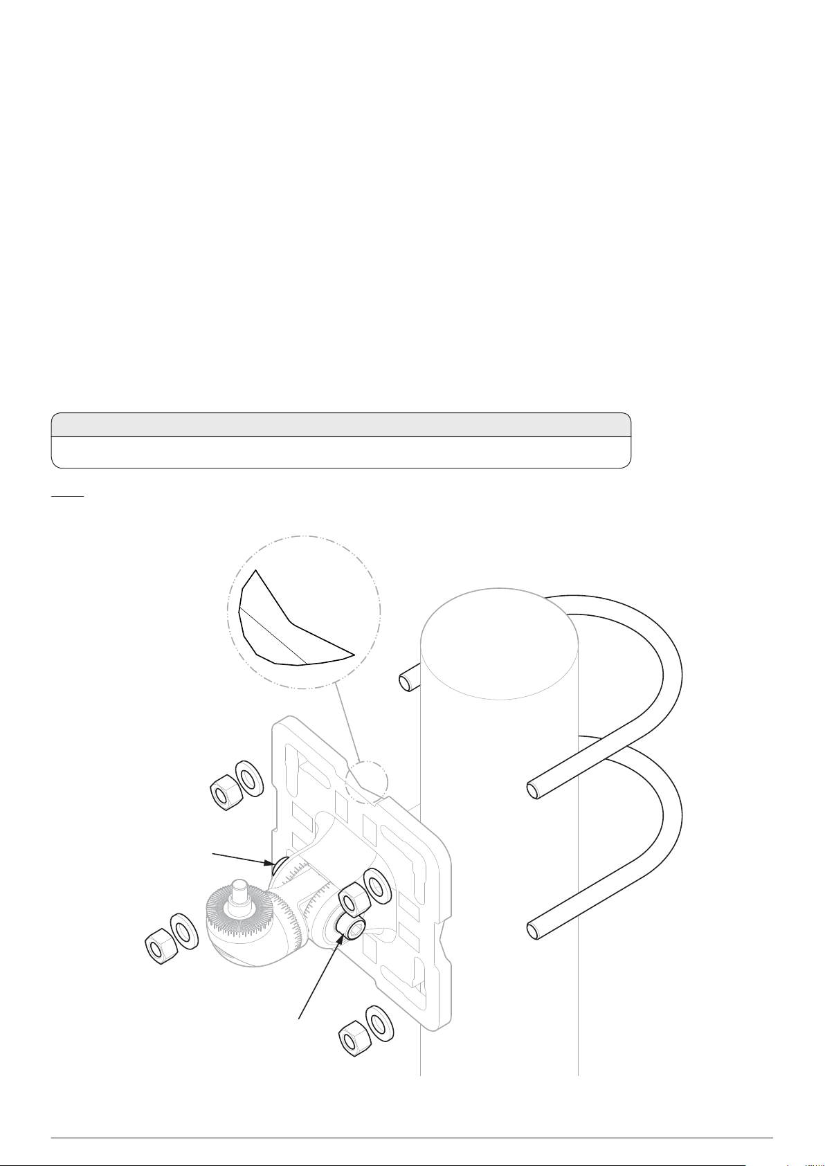
3. Attach the assembled Standard Adjustable Mounting Bracket (or Large Adjustable Mounting Bracket) to the pole. Align the bracket
flange V-groove with the pole for a good fit. Fix the bracket with two U-bolts and four nuts with washers. Alternatively, fix the bracket
using the Worm Drive Clips. Refer to the figure below.
4. Unscrew both horizontal M10 bolts by 23 turns.
5. Adjust the pivot in horizontal position.
6. IMPORTANT: First, tighten the left-facing horizontal M10 bolt (refer to the figure below) to fix the pivot in horizontal position
(torque 30 Nm/22 lb-ft).
7. IMPORTANT: Second, tighten the right-facing horizontal M10 bolt (refer to the figure below) to fix the pivot in horizontal position
(torque 30 Nm/22 lb-ft).
CAUTION
225 Mechanical Installation
Use of the Worm Drive Clips is NOT recommended for installation on moving objects, e.g., gas carriers.
NOTE
All Mounting Bracket bolts are captive to ensure that they are not accidentally dropped during installation.
V-GROOVE
DETAIL
Left-facing
horizontal
M10 bolt
Right-facing
horizontal
M10 bolt
Figure 11.Standard Adjustable Mounting Bracket fitment to pole with U-bolts
Searchzone Sonik − Technical ManualPN 2331M1220 Issue 1 11/2018
Page 23
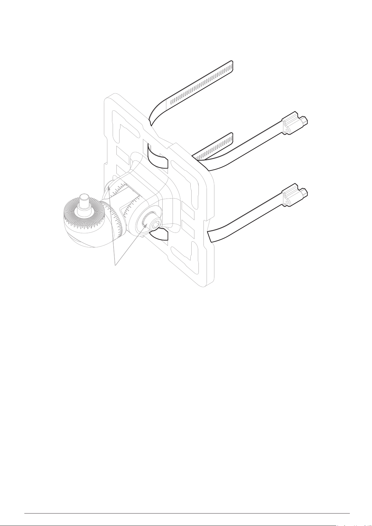
235 Mechanical Installation
Horizontal M10 bolts
Figure 12.Standard Adjustable Mounting Bracket fitment using Worm Drive Clips
Searchzone Sonik − Technical ManualPN 2331M1220 Issue 1 11/2018
Page 24
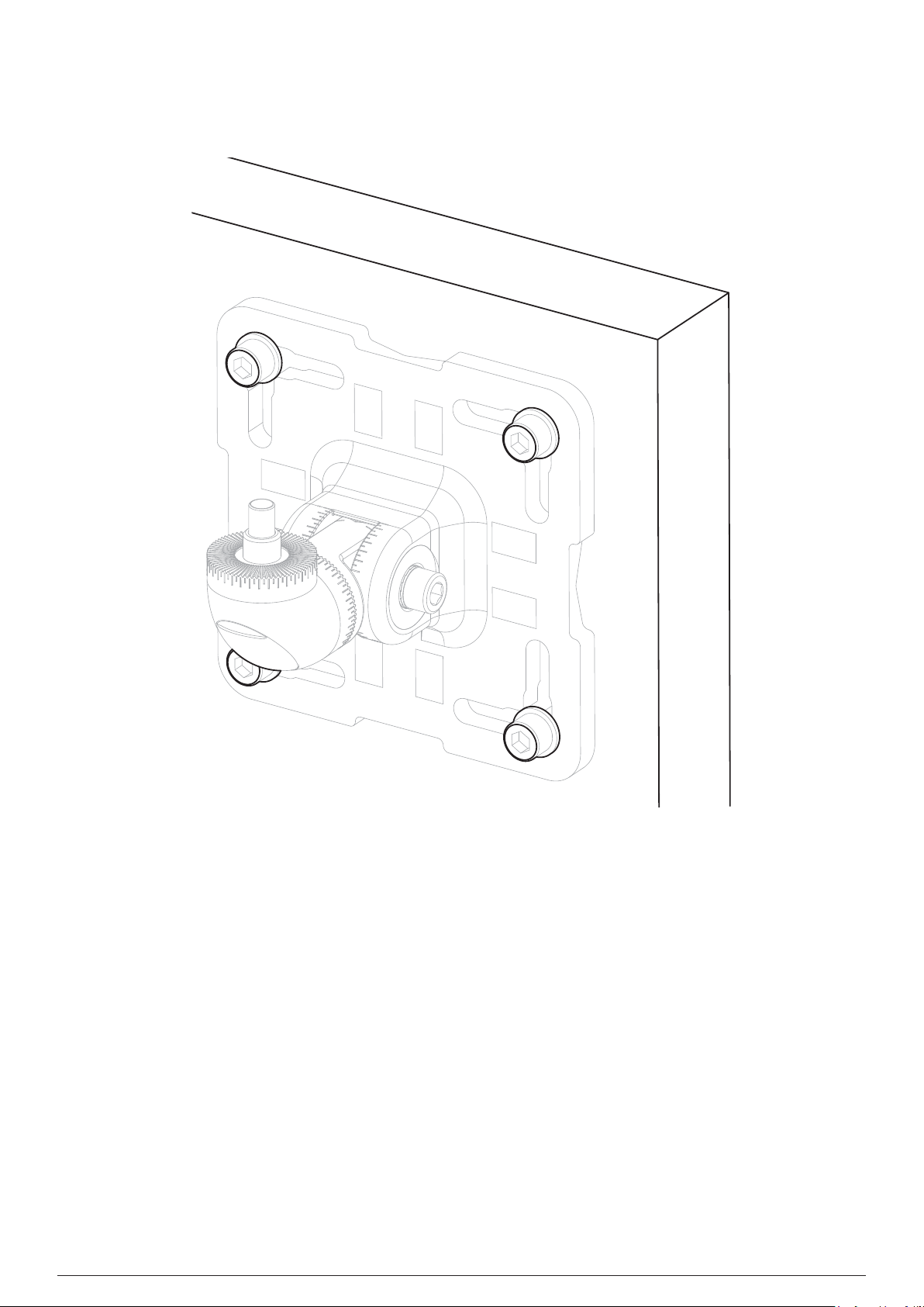
5.6Wall Mount Installation
For installation onto a wall, use M8 or M10 mounting bolts with washers (not supplied).
245 Mechanical Installation
Figure 13.Wall mount installation
Searchzone Sonik − Technical ManualPN 2331M1220 Issue 1 11/2018
Page 25
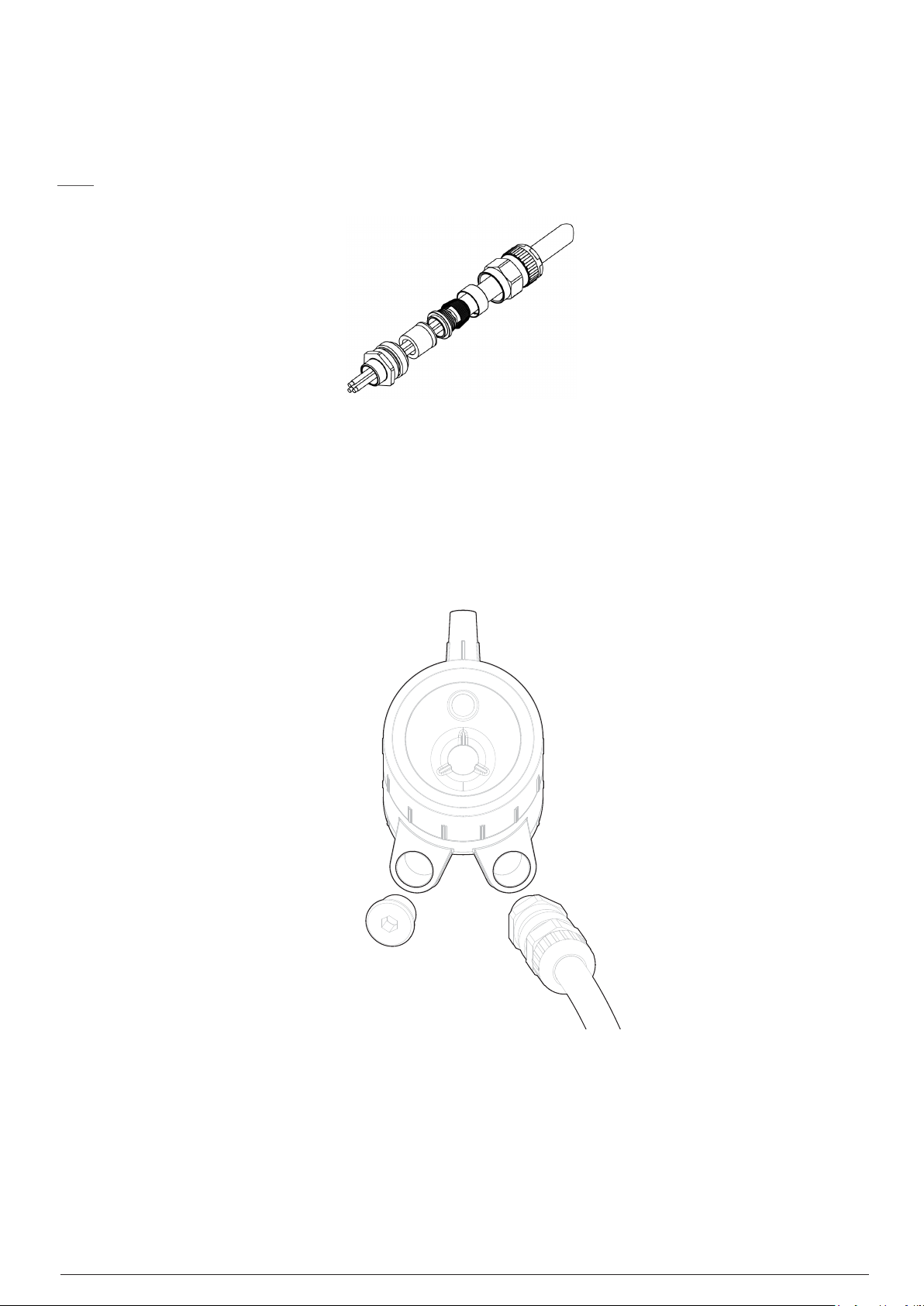
5.7Assemble Cable Glands
Refer to the original manufacturer’s assembly instructions for the particular cable gland type. The wiring compartment is certified to be
able to use EX d or Ex e glands to suite local requirements. Leave a service loop in the cable as per site standard procedures.
NOTE
Use certified cable glands and blanking plugs as per local standards.
Figure 14.Example of cable gland
255 Mechanical Installation
5.8Connect Cable Glands to the Searchzone Sonik
1. Fit the cable glands to the Detector.
2. Fit a Stopping Plug to any unused cable entry.
3. Tighten the gland nuts and Stopping Plugs as per the manufacturer’s instructions.
Figure 15.Connect cable glands to the Detector
Searchzone Sonik − Technical ManualPN 2331M1220 Issue 1 11/2018
Page 26
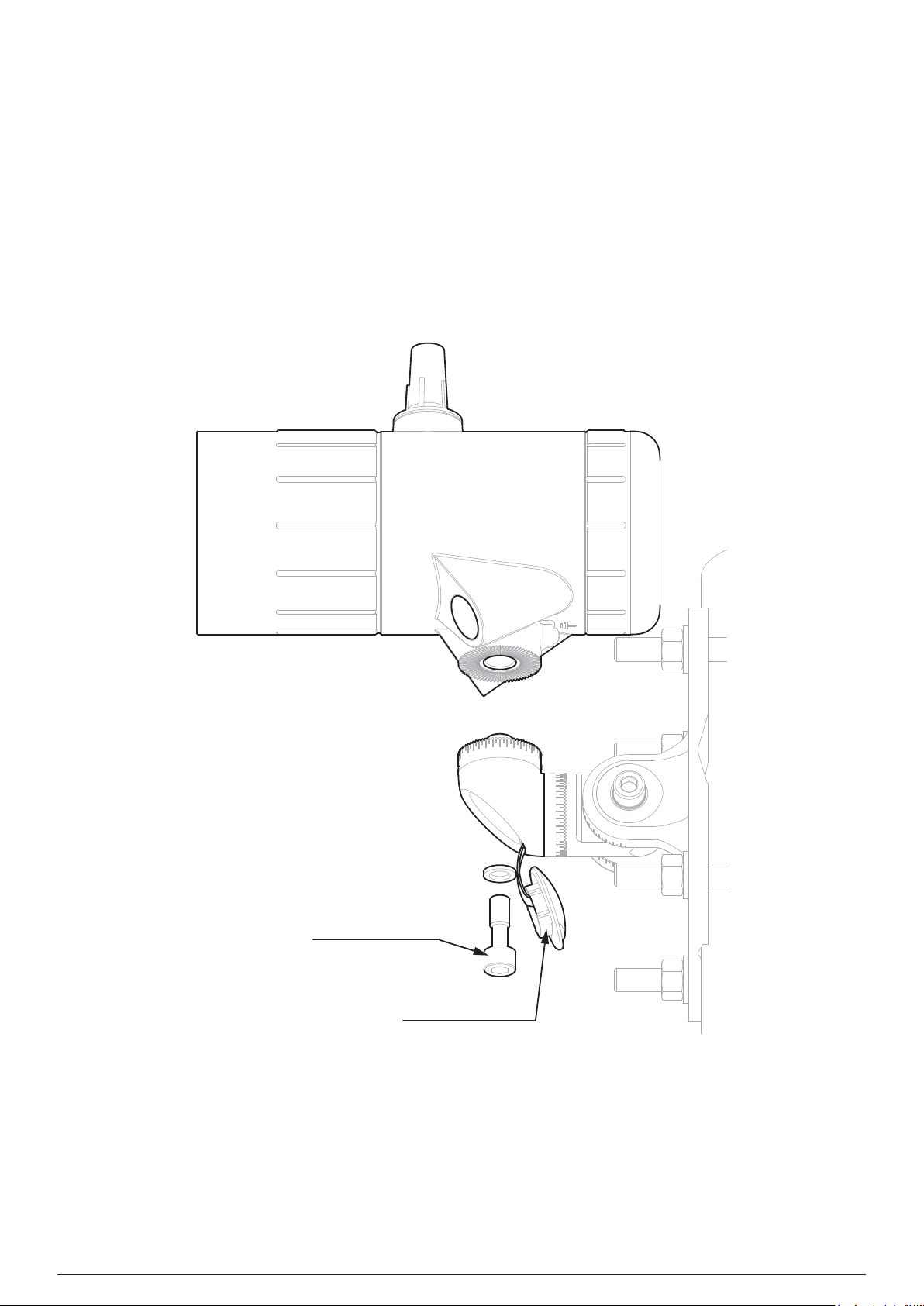
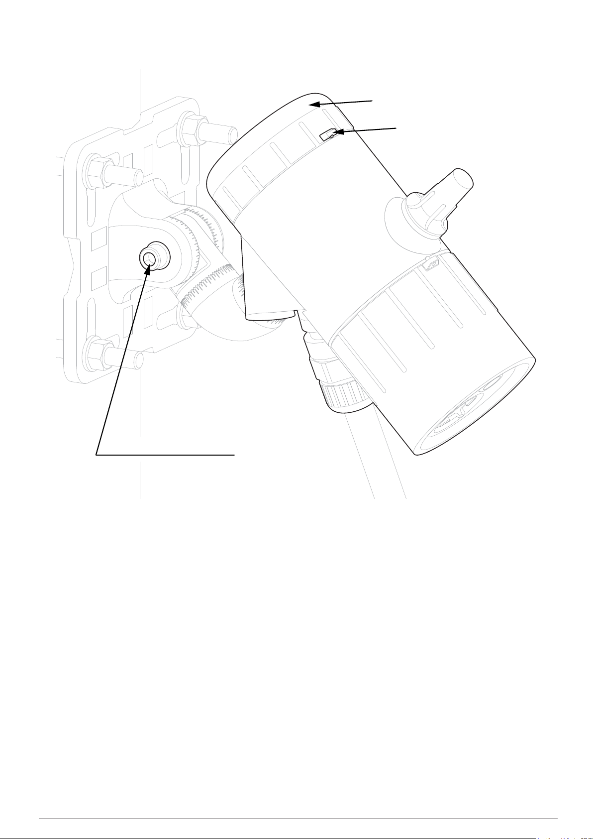
5.9Detector Attachment
1. Remove the bolt cover plate (refer to the figure below).
2. Attach the Searchzone Sonik to Standard Adjustable Mounting Bracket.
3. Hold in place and hand-tighten the vertical M10 bolt with washer. The Standard Adjustable Mounting Bracket is designed so that
Searchzone Sonik sits on the top spigot and is balanced to aid installation.
4. Aim the detector in the desired direction and hand-tighten the left-facing horizontal M10 bolt. Only hand fit the right-facing
horizontal M10 bolt at this stage.
5. Check the final positioning of the detector and make adjustments if necessary.
6. Tighten only the left-facing horizontal M10 bolt to a final torque of 30 Nm (22 lb ft).
7. Tighten the remaining bolts to a final torque of 30 Nm (22 lb ft).
8. Push home the bolt cover plate.
265 Mechanical Installation
Vertical M10 bolt
Bolt cover plate
Figure 16.Detector attachment
5.9.1Detector removal
1. IMPORTANT: First, loosen the right-facing horizontal M10 bolt by 23 turns.
2. IMPORTANT: Second, loosen the left-facing horizontal M10 bolt by 23 turns.
3. Set the vertical position of Detector to 0°.
4. Hold the detector body and loosen the vertical M10 bolt.
5. Remove the Searchzone Sonik from Standard Adjustable Mounting Bracket.
Searchzone Sonik − Technical ManualPN 2331M1220 Issue 1 11/2018
Page 27
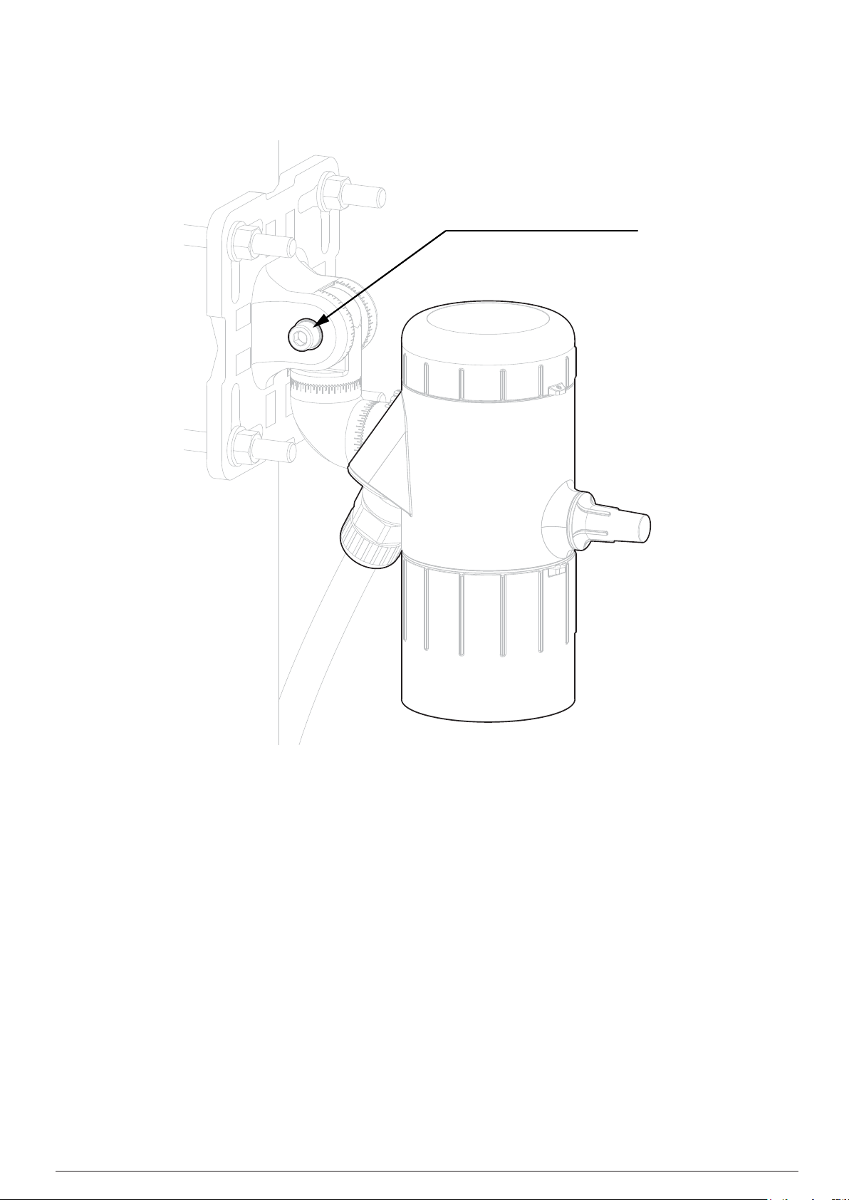
Left-facing horizontal M10 bolt
275 Mechanical Installation
Figure 17.Set the vertical position of Detector to 0°
Searchzone Sonik − Technical ManualPN 2331M1220 Issue 1 11/2018
Page 28
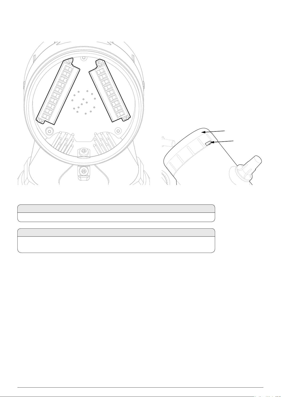
5.10Connect Wires to PCB Terminals
285 Mechanical Installation
Wiring Compartment
Cover
Grub screw
Figure 18.PCB Terminals
CAUTION
Remove power from Searchzone Sonik before performing any electrical installation or maintenance.
CAUTION
The equipment features pluggable connectors that are mechanically locked into position. These are
not accessible by the user during normal operation.
1. Loosen the grub screw.
2. Unscrew the Searchzone Sonik wiring compartment cover.
3. Unscrew and remove the pluggable connectors.
4. Connect wires as per local procedures. The connectors are clearly identified. Refer to the diagrams and tables in the
Electrical Installation section of this manual for information on wiring.
5. Ensure that the O-rings on the detector body and in the end cap are properly fitted and not damaged.
6. Ensure that the threads of the wiring compartment cover are clean of dust and lubricated with a suitable anti-seize compound.
7. Screw on the wiring compartment cover.
8. Tighten the grub screw to a final torque of 1.1 Nm (0.81 lb-ft)
9. Ensure the horizontal M10 bolts are loosened by 23 turns.
10. Use the graduated adjustment and angle scale to aim the Detector to the required position.
11. IMPORTANT: First, tighten the left-facing horizontal M10 bolt to a final torque of 30 Nm (22 lb-ft).
12. IMPORTANT: Second, tighten the right-facing horizontal M10 bolt to a final torque of 30 Nm (22 lb-ft).
13. Fit the sunshade in place. Refer to section 5.11 Sunshade Installation for instructions.
Searchzone Sonik − Technical ManualPN 2331M1220 Issue 1 11/2018
Page 29
Wiring Compartment
Cover
Grub screw
295 Mechanical Installation
Left-facing horizontal M10 bolt
Figure 19.Example position of 45°
Searchzone Sonik − Technical ManualPN 2331M1220 Issue 1 11/2018
Page 30
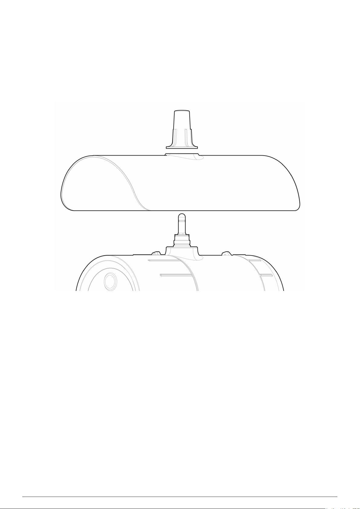
5.11Sunshade Installation
1. Unscrew the antenna cover from the top of the detector.
2. Fit the standard (supplied) or stainless steel sunshade (optional) onto Searchzone Sonik.
3. Ensure the O-ring around the antenna is not damaged and is properly fitted.
4. Screw the antenna cover back onto the antenna.
5. Tighten the antenna cover to a final torque of 5 Nm (7 lb-ft).
305 Mechanical Installation
Figure 20.Sunshade and antenna cover
Searchzone Sonik − Technical ManualPN 2331M1220 Issue 1 11/2018
Page 31

6 Electrical Installation
CAUTION
Remove power from the Searchzone Sonik before performing any electrical installation or
maintenance.
6.1Power Supply Requirements
The Searchzone Sonik detector requires a voltage supply of 18 - 32 Vdc (nominal 24 Vdc). Power consumption is 4 W maximum when
the internal heater is not active, i.e. for ambient temperatures above 30°C. At lower ambient temperature the internal heater is active
and power consumption may reach up to 15 W.
Ensure that the minimum required supply voltage 18 VDC is present at the detector, taking into account the voltage drop due to cable
resistance.
Note
Make allowance for the insertion loss resistance.
316 Electrical Installation
The maximum loop resistance in the field cable is calculated as follows:
As an example, V
the connected power supply or control system. Consult the manual of that equipment for this information.
CAUTION
The detector 24 V power supply and 420 mA current loop power supply must be of an isolating type
(galvanic isolation from mains, providing basic insulation) but does not need to be a Class II (SELV)
power supply.
CAUTION
If mains voltage is connected to more than one relay, all relays must be connected to the same phase
of the mains network. Using different phases is not allowed.
detector min
= 18 V; P
= 4 W or 15 W (dependent on environmental conditions) V
max
6.1.1Internal Battery Cell
will depend upon
controller
A primary cell featuring an expected operating life of 10 years is fitted internally. This is not accessible and replacement must only be
conducted by an authorized service centre.
6.2420 mA Current Loop
The Detector provides a 420 mA current loop with HART Communication which can be user configured as a Sink, Source (3Wire) or
Isolated (4Wire) electrical interface, based on installation requirements.
Depending on configuration, the 420 mA current loop output can provide:
• discrete indication of operating modes (Normal operation, Pre-alarm, Alarm) and special states (Fault, Warning, Inhibit, Over-range)
• proportional output to ultrasound pressure level (dB SPL) and a discrete indication of special states (Fault, Warning, Inhibit, Overrange).
Searchzone Sonik − Technical ManualPN 2331M1220 Issue 1 11/2018
Page 32

326 Electrical Installation
Ø=78 mm
THIS DOCUMENT HAS BEEN GENERATED USING ADOBE
INDESIGN AND MUST ONLY BE UPDATED BY INDESIGN
The Searchzone Sonik features HART communications to provide access to the detector from a control system or hand-held device for
the purpose of configuration and to provide status and diagnostic information.
The total load resistance for the 420 mA current loop shall be less than 600 Ω, including the resistance of the 420 mA cable and
input impedance of the equipment to be connected. To ensure reliable HART communications, the minimum loop resistance is 250 Ω.
If HART communications is not required, the minimum loop resistance is 100 Ω.
If the 420 mA current loop is not used, a jumper must be connected between 420 mA+ (terminal 5) and 24V DC+ (terminal 8) and a
load resistor must be connected between 420 mA (terminal 6) and 0V DC (terminal 9). It is recommended to use a 470 Ohm, 1/4 W
resistor (250 to 400 Ω if HART is required). With the 420mA current loop configured this way the HART facility can still be used with a
HART hand held unit using terminals 20 and 21 inside the wiring compartment.
CAUTION
The maximum permissible mA loop voltage is 32 VDC and the maximum current is 22 mA.
6.3Relays
The Searchzone Sonik detector features 3 SPDT relay outputs for alarm and fault indication. Relay 1 is for alarm level 1, relay 2 is for
alarm level 2, and relay 3 indicates faults. The fault relay is normally energized and when energized indicates proper operation (no faults
present).
In the event of power failure or fault, the COMNO connection will open (the fault relay may be user configured as normally deenergized.)
6.4Connections / Wiring Diagram
Note
24 V pins number 7 & 8 and 0 V pins number 9 & 10 are internally linked.
10 0V DC
9 0V DC
8 24V DC
7 24V DC
6 420mA 5 420mA +
4 RS485 D
3 RS485 D
2 RS485 B
1 RS485 A
Registration
Serial Number:
1234567890
Activation Key:
ABCDEFGHIJKLM
11 A2 COM
12 A2 NC
13 A2 NO
14 A1 COM
15 A1 NC
16 A1 NO
17 FLT COM
18 FLT NC
19 FLT NO
20 HART +
21 HART -
QR CodeQR Code
Figure 21.Terminal Connector Label
Searchzone Sonik − Technical ManualPN 2331M1220 Issue 1 11/2018
Page 33

336 Electrical Installation
External earth connection
Figure 22.Terminal Wiring Compartment
6.4.1Terminal Wiring Description
Number Marking Description
1 RS485 A RS485 A (positive)
2 RS485 B RS485 B (negative)
3 RS485 D RS485 D (cable shielding)
4 RS485 D RS485 D (cable shielding)
5 420mA+ mA signal +
6 420mA mA signal 7 24V DC Input power +
8 24V DC Input power +
9 0V DC Input power 0V
10 0V DC Input power 0V
Internal earth connection
Searchzone Sonik − Technical ManualPN 2331M1220 Issue 1 11/2018
Page 34

Number Marking Description
11 Alarm 2 COM Alarm Relay 2 COM contact
12 Alarm 2 NC Alarm Relay 2 NC contact
13 Alarm 2 NO Alarm Relay 2 NO contact
14 Alarm 1 COM Alarm Relay 1 COM contact
15 Alarm 1 NC Alarm Relay 1 NC contact
16 Alarm 1 NO Alarm Relay 1 NO contact
17 Fault COM Fault Relay COM contact
18 Fault NC Fault Relay NC contact
19 Fault NO Fault Relay NO contact
20 HART+ HART hand-held temporary
connection (positive)
21 HART HART hand-held temporary
connection (negative)
Unused conductors must be suitably terminated. Wiring must be in accordance with local, national and company regulations.
Exposed or bare conductors must be avoided.
346 Electrical Installation
CAUTION
The maximum permissible mA loop voltage is 32 VDC and the maximum current is 22 mA.
Note
Searchzone Sonik is protected against accidental reversed polarity in wiring.
6.4.2Searchzone Sonik Connection for mA loop Configuration as Current Source
CAUTION
Ensure that jumper wires are installed applicable for the selected mA current loop configuration.
Figure 23.mA loop configuration as current source
Searchzone Sonik − Technical ManualPN 2331M1220 Issue 1 11/2018
Page 35

6.4.3Searchzone Sonik Connection for mA Loop Configuration as Current Sink
Figure 24.mA loop configuration as current sink
356 Electrical Installation
6.4.4Searchzone Sonik Connection for mA Loop Configuration as Isolated Output
Figure 25.mA loop configuration as isolated output
6.5Cabling Recommendations
The cable used must be appropriate for the hazardous area classification and must meet local, national and company regulations. The
use of industrial grade, screened field cable is recommended.
An example may be a 3-core copper cable with screen (minimum 90% coverage) and suitable mechanical protection (e.g. steel wire
armour) to suit an M25 or 3/4” NPT gland entry or conduit, suitable when mA loop and Modbus are used while relay outputs are not
utilized.
The allowable conductor size for the terminals is 0.25 – 2.5 mm² (24 - 12 AWG). The Searchzone Sonik terminals will accept only wire
sizes (solid-core or stranded) in this range. The temperature rating of the conductors and cable glands should be greater than 80°C. The
terminals should be torqued between 0.5 Nm to 0.6 Nm (0.3680.442 lb.ft).
Ensure that the cable gland is installed correctly and fully tightened. All unused cable/conduit entries must be sealed with a suitable
certified blanking plug. Use appropriate and certified cable glands, adapters and/or cable fittings to meet local standards.
Searchzone Sonik − Technical ManualPN 2331M1220 Issue 1 11/2018
Page 36

6.6Earthing Recommendations
CAUTION
Any earthing regime employed must avoid earth loops.
The following information is provided to assist with proper earthing of the Searchzone Sonik:
• The Searchzone Sonik has both INTERNAL and EXTERNAL earth points provided (see Electrical Connections). This is to facilitate
connection of the detector to protective earth.
The INTERNAL earth point is marked with ground symbol in circle It shall be used for the equipment grounding connection.
Internal earth must be at least equal in mm2 to the incoming power conductors.
The EXTERNAL earth point is marked with ground symbol without circle It provides a supplementary bonding connection, which
provides facility for connection of field wiring conductors of at least 4mm2.
• Field cable screens should be connected to instrument earth at the control room. The other end of the field cable screen should be
suitably terminated or isolated. It should not be connected to internal earth point.
6.7Modbus
366 Electrical Installation
Refer to the Communications section of this manual for more information on Modbus.
Searchzone Sonik − Technical ManualPN 2331M1220 Issue 1 11/2018
Page 37

7 Commissioning and Configuration
7.1First Time Switch On
7.1.1Pre-power Check
1. Check that the working environment temperature is within the range given in the Specifications section of this manual.
2. Check that the Searchzone Sonik detector is mounted correctly and secured in its position. Refer to the Mechanical Installation and
Electrical Installation sections of this manual for more information.
3. Check that the Searchzone Sonik unit is wired correctly. Refer to the Electrical Installation section of this manual for more
information.
7.2Operating Function Verification
Check that the Searchzone Sonik detector safety outputs are working properly.
Check that the Searchzone Sonik detector is positioned correctly so as to cover the risk being monitored.
Perform a functional test where appropriate.
377 Commissioning / First Time Operation / Configuration
7.3Communication
NOTE
The prerequisite to commissioning using Bluetooth is to have the Searchzone Sonik Mobile App installed to a suitably-approved mobile
device and that the user be fully registered to the Honeywell User Management Server (UMS).
7.3.1Bluetooth®
The Searchzone Sonik detector features a Bluetooth interface that allows non-intrusive connection using a mobile device running the
Searchzone Sonik App. The Bluetooth interface is accessed by the mobile device that supports Bluetooth.
Refer to the Mobile App section of this manual for more information on Bluetooth communication link.
The Searchzone Sonik detector supports Bluetooth point-to-point mode of operation. While there is a connection between the
Searchzone Sonik and a mobile device, the detector cannot be scanned or accessed by another mobile device.
If there is no active Bluetooth communication for 10 minutes, the Searchzone Sonik detector will terminate the Bluetooth connection
automatically.
The communication range will vary depending on the field situation and installation location of Searchzone Sonik. Optimal range will be
achieved when line-of-sight between the Searchzone Sonik detector and the mobile device is achieved.
7.4Settings and Configuration
The Searchzone Sonik Mobile App is the primary tool for configuring the detector. The configurable settings are as follows:
Detector ID
Operation mode
Algorithm mode
Inhibit level
Alarm set point
Warning level
Fault level
Over-range level
Alarm 1 level
Alarm 2 level
Alarm delay
Proof test interval
Relay 1, Relay 2, Relay 3
LED mode
LED intensity
Inhibit timeout period
Set access PIN
Refer to the Mobile App section of this manual for more instructions and guidance on installation, commissioning and maintenance.
NOTE
When used with a Touchpoint Pro controller, the positive and negative suppression values must be set correctly otherwise the controller
will report a detector fault. Similarly, when used with a Touchpoint Plus controller, the upper and lower deadband values must be set up.
Searchzone Sonik − Technical ManualPN 2331M1220 Issue 1 11/2018
Page 38

7.5Delay Time
A delay time is used to minimize the possibility nuisance alarms and/or when immediate response is not required.
The delay time setting should be assessed with regards to the following:
• Searchzone Sonik proximity to monitored object/area or to the source of ultrasonic noise
• The gas type being monitored and the potential severity of a resultant leak
• Existing site protocols and local regulations
The Searchzone Sonik raises two types of alarm:
1) Alarm 1 − suspected alarm activated instantaneously after the measured sound pressure level exceeds the alarm threshold, and
is maintained above the Alarm 1 level. At this point, the delay time is applied. If Alarm 1 is still active after the delay time has passed,
Alarm 2 is activated.
2) Alarm 2 − confirms Alarm 1. Following activation of Alarm 1, the delay timer starts. If an alarm signal is still present after this time
then Alarm 2 is activated.
The delay time is set by user within range from 1 to 600 seconds. Refer to the Mobile App section of this manual for more instructions.
7.6Background Noise Rejection
387 Commissioning / First Time Operation / Configuration
Use the Searchzone Sonik Mobile App to select between Standard and Focus background noise rejection algorithms.
Refer to the Mobile App section of this manual for more instructions.
7.7Performance Verification
Note
Be aware of other ultrasonic gas leak detectors that may be within range before performing any performance verification. To minimize
the risk of nuisance alarms, inhibit those detectors where appropriate.
Testing Using Air Cylinder
Use a small canister of compressed air, operated in the vicinity (maximum 5 m of the Searchzone Sonik detector) to test the operation of
the detector.
WARNING
Manipulation of compressed gas cylinders is potentially hazardous and should only be performed by trained
personnel.
Ensure safety measures are taken in the workplace.
Ensure compliance to local regulations and laws.
Searchzone Sonik − Technical ManualPN 2331M1220 Issue 1 11/2018
Page 39

8 Operation
8.1Operation
This chapter describes the operation of Searchzone Sonik in different states (Normal, Alarm, Fault, Periodic Test).
8.2Status Signalling
Searchzone Sonik utilizes several outputs to indicate its status, namely the high visibility indicator, the mA Loop, relays and digital
communication interfaces (Bluetooth, HART and Modbus). The following sections describe the instrument behaviour.
8.2.1Visual Status Indicator
NOTE:
The visual status indicator is not considered a safety output. Its behaviour is configurable and may indicate different states than other
outputs.
Searchzone Sonik is equipped with a high visibility LED status indicator the function of which is to visually indicate the status of the
instrument. See the following table for behaviour configuration information:
398 Operation
Operation without
Bluetooth
Fault Yellow Yes Default
Inhibit Yellow No Default
Warning Yellow Yes Default
Normal Green No Default
Normal Green Yes Optional
Normal None No Optional
Alarm Red Yes Default
Over-range Red Yes Default
Operation with
Bluetooth
Fault Yellow Yes Default
Inhibit Yellow No Default
Warning Yellow Yes Default
Normal Blue No Default
Normal Blue Yes Optional
Alarm Red Yes Default
Over-range Red Yes Default
Connecting Blue Yes Default
Connected Blue No Default
Warning Blue alternating No Default
Colour Flashing Setting
Colour Flashing Setting
Searchzone Sonik − Technical ManualPN 2331M1220 Issue 1 11/2018
Page 40

408 Operation
8.2.2mA Loop Status
The Searchzone Sonik is equipped with a 420 mA loop output which can operate in source or sink mode. Source and sink modes are
configured by wiring. For more information see the wiring diagram in Electrical Installation section. This output is a safety-related output
and is compatible for use in SIL 2 applications. Normal operation and alarm conditions are indicated between 4 to 20 mA, depending
on configuration.
The mA Loop offers two modes of operations:
1) Proportional to the detected sound pressure level.
2) Discrete, where the output will switch between distinct levels, based on detector status.
Fault and Inhibit indications are signalled with values lower than 4 mA, Over-range indications are signalled with value higher than
20 mA. Output levels of the 420 mA loop are configurable,
See the following table for output levels:
Mode Default Value (mA) Min Value (mA) Max Value (mA)
Discrete Mode Proportional Mode
Fault 1 0 3.6
Inhibit 2 1 3.6
Warning 3 1 4
Normal 4 Proportional to
sound pressure
level
Pre-alarm 16 Not available 4 20
Alarm 20 Not available 4 20
Over-range 21 20 22
4 20
8.2.3Relay Signalling
The Searchzone Sonik is equipped with three independent relays, designated for Fault, Alarm1 and Alarm2. These relays are safetyrelated outputs and are compatible for use in SIL1 applications. The Fault relay is used for indication of various fault conditions; the
Alarm1 and Alarm2 relays are used to indicate alarm conditions. All the relays are configurable, giving an option of Normally Energised
/ De-energised and latching / non-latching of events.
CAUTION
Fault relay will be triggered when user performs Inhibit operation.
8.3Normal Operation
During normal operation, the 420 mA output represents 0 100% sound pressure level range, depending on the selected mode and
the SPL level.
The output is:
1) Linear within the range of SPL in Proportional mode
2) 4 mA in Discrete mode
Analog outputs lower than 4 and higher than 20 mA represent diagnostic information. The fault relay in this mode is normally energized
and the visual indicator is lit steady green.
8.4Operation During Fault
If Fault is indicated the visual indicator starts to flash in yellow, the fault relay is de-energized and 420 mA loop is set to 1 mA.
NOTE:
HART communication requires >1 mA current output to support transmission. If the fault level is configured to be below 1 mA, HART
communications will cease.
Searchzone Sonik − Technical ManualPN 2331M1220 Issue 1 11/2018
Page 41

418 Operation
8.5Operation During Alarm
Searchzone Sonik features three levels of alarm. PreAlarm, Alarm and Overload.
8.5.1Pre-alarm
During PreAlarm, the Alarm1 relay is energized/de-energized depending on its configuration. The 420 mA loop is set to 16 mA in
Discrete mode. It is proportional to the sound pressure level (SPL) in Proportional mode. The visual indicator flashes red.
8.5.2Alarm
During Alarm, the Alarm2 relay is energized/de-energized depending on its configuration. The 420 mA loop is set to 20 mA in Discrete
mode. It is proportional to SPL in Proportional mode. The visual indicator flashes red.
8.5.3Overload
Searchzone Sonik indicates Overload when an exceptionally high SPL is detected (>140 dB). During Overload, the Fault relay is
additionally energized/de-energized depending on its configuration. The 420 mA loop is set to >20 mA in both Discrete mode and
Proportional mode. The visual indicator flashes red.
Searchzone Sonik indicates Fault for thirty seconds after the Overload condition is no longer detected.
Note
Searchzone Sonik logs 10 minutes of recording for each of the last 5 verified alarms. The 10 minutes are divided into 5 minutes before
and 5 minutes after the alarm.
Searchzone Sonik − Technical ManualPN 2331M1220 Issue 1 11/2018
Page 42

9 Mobile App
9 Mobile App
The Searchzone Sonik App is an Android-based mobile application that is used to configure and commission
Searchzone Sonik detectors.
CAUTION
The Searchzone Sonik App has been designed and tested to run on the Ecom SmartEX 01
mobile phone. Operation on other mobile devices is possible.
9.1General User Access
There are three methods of accessing detector from the mobile device:
1) Normal access. The user is registered and associated with the company account to which the detector is registered,
and has Internet access.
2) Off-line access. The user is registered and associated with the company account to which the detector is registered,
but has no Internet access at the time of connection. The user must periodically log in to the App when Internet
access is available, to maintain the security certificate.
3) Ad-hoc access. The user is registered, but not with the company account associated with the detector. The user
must have access to the detector Serial Number and Activation Key in order to access the detector. This access is
only available when no Internet connection is available, or the device’s Internet access has been disabled. This type
of access is not intended for normal day-to-day use.
42
Access should be granted only to suitably trained and accredited engineers.
A user of the system is able to:
1) Commission (set-up) the Searchzone Sonik – the App connects to the detector using Bluetooth and takes the user
to the commissioning work flow.
2) Create and manage other users. The App allows user to access the user management features after successful
authentication and login.
9.2Terminology
Admin User The user who initially creates a Company account and registers
a detector to that account is created as an Admin user for the
company.
An Admin user can invite further individuals as users, using the
App. The new users will become Admin users once they have
been validated.
Visitor A user who creates an account but does not register a detector
remains a Visitor.
Searchzone Sonik − Technical ManualPN 2331M1220 Issue 1 11/2018
Page 43

9 Mobile App
9.3Communications
User creation requires the Sonik Searchzone App to be installed on a suitable Android device featuring Bluetooth and
an Internet connection.
9.3.1Company Account Management
The Initial Admin User is considered the first user who is registered that will go on to create a Company group. Once
done, they will then be able to create and invite subsequent users to that Company group.
In order to create this initial Admin user, they will need to register at least one Searchzone Sonik detector with their
account. The account creation will not be completed until this is done.
Note
It is not possible for an existing user to be added to a new Company Group. Please use the Add User function in the
User Management section of the App to add additional users to the Company group, using a new email address.
Note
Once the user is registered on ums.honeywell.com, they can use the same credentials (and Company Group) to access
other Honeywell Industrial Safety products.
43
9.3.2Creating a New Company Account
Use the following method to create a new Company Account and Administrator. To add a new user to an existing
account, use the method described in section 9.3.2.3 Adding Further Users to Company Account
To create a new Company Account, you will be required to provide an email address, which will become your unique
user name for the account.
Enter the following data:
• First name
• Last name
• Email address
• Password
The password must contain:
- at least 8 characters
- at least 1 upper case character (AZ)
- at least 1 lower case character (a-z)
- at least 1 digit (09)
- at least 1 special character
The password must NOT contain:
- the account name itself
- a consecutive string of three or more repeated characters (e.g.,
AAA1111)
- the names (or abbreviations) of months or the weekdays (e.g., JAN,
MON, etc.)
After you have entered all the required information, tap on ‘CREATE ACCOUNT‘ button. This will trigger the
Verification Email to be sent to the email address that was given for that user.
A verification email will be sent to the given email address within 15 minutes. You must respond to the email within
24 hours before it expires.
Open this email and click on the verification link on any suitable device (i.e., PC, tablet or smartphone). You will then be
directed to a web page where you will need to re-enter the password chosen on the Account Creation page. Click or tap
on OK.
Searchzone Sonik − Technical ManualPN 2331M1220 Issue 1 11/2018
Page 44

9 Mobile App
Return to the Searchzone Sonik App. The UMS will automatically complete the account verification process.
Note
The verification link will expire after 24 hours. After this has passed, repeat the steps in section 9.3.2 and a new
verification link will be sent to the nominated email address.
44
9.3.2.1First Detector Registration
If the Company Account being created is the Initial Admin User for a company group, you must register
at least one Searchzone Sonik detector in order to complete the User Registration. Refer to section
9.4 Detector Registration on how to do this.
9.3.2.2Security Certificates
Each user requires a valid certificate to be loaded on each mobile device used to access Searchzone Sonik
detectors. The certificate is valid for 365 days. A new certificate is automatically downloaded each time
you log into the App as long as there is a connection to the Internet.
Once the certificate is downloaded, you will then be
prompted to register a detector to fully enable the
features of the Searchzone Sonik App.
Searchzone Sonik − Technical ManualPN 2331M1220 Issue 1 11/2018
Page 45

9.3.2.3Adding Further Users to Company Account
When authenticated, new users will have the same administrative rights as the Initial User and will be able
to access all detectors already registered, in addition to being able to register further detectors.
Advise the new user that they will receive an authentication email, and ensure that they are able to respond
to the email within 24 hours. Agree an initial password.
Navigate to the ‘SETTINGS’ menu, go to ‘User Management’ screen in the Searchzone Sonik App and tap
on the ‘+’ button in the top right-hand corner.
Enter the user’s email address, First Name, Last Name and the initial password. Tap on the ‘ADD USER’
button. The user will receive a confirmation email, normally within 15 minutes.
They will need to click on the link in that e-mail and they be directed to a web page where you will need to
re-enter the password chosen on the Account Creation page. Tap on ‘OK’.
That user will then be able to log in to their account.
Repeat this process to add further users.
Refer to section 9.11 User Management for more information.
9.3.2.4Completing the Account Setup
Once you have successfully set up the account, you and
the users that you have added will be able to access all of
the detectors that you have registered against it.
9 Mobile App
45
9.3.2.5Logging In to Searchzone Sonik App (with Internet Connection)
Connect to the Internet and log in to the App. Open the App on your mobile device and enter the email
address and password for your account.
Your certificate will be automatically updated and a confirmation message shown.
You will be presented with the Home Page with three key options:
Search for detectors (DETECTORS)
View and manage reports (REPORTS)
View and manage app settings (SETTINGS)
Navigate to the required function by simply tapping on it.
Searchzone Sonik − Technical ManualPN 2331M1220 Issue 1 11/2018
Page 46

9.3.2.6Logging In to Searchzone Sonik App (without Internet Connection)
If your mobile device is not connected to the Internet, you can still log in to the Searchzone Sonik App and
access registered detectors. You must have previously carried out at least one normal login (see section
9.3.2.5), with an Internet connection.
Your security certificate will remain valid for 365 days, allowing you to login off-line. When this period
expires you will need to log in again with an Internet connection to update your security certificate. You
will not be able to access settings or detectors until the security certificate has been updated.
9.3.2.7Forgotten Password
Go to the login screen.
Tap on ‘Forgot your password?’.
Enter the email address provided during the creation of the
account and tap on ‘Continue’.
Check your email inbox for the password reset link and
instructions.
9 Mobile App
46
Follow the instructions and reset your password.
9.3.2.8Changing Password
Go to the main menu and tap on the avatar icon to access
account details.
Alternatively, choose Settings / User Management /
Account Details.
Tap on ‘CHANGE PASSWORD’.
Searchzone Sonik − Technical ManualPN 2331M1220 Issue 1 11/2018
Page 47

9.3.2.9Detector Registration
To register a detector:
• Ensure that you have an Internet connection.
• Ensure that you have the serial number of the detector you wish to register together with either the
Activation Key or the activation QR code.
The Activation Key and QR code may be obtained from:
• The Registration Sheet supplied with detector
• Site records
• The label inside detector wiring compartment
• By contacting your Honeywell Customer Support
Tap on the preferred method for entering this information
and then either enter the Serial Number and Activation
Key manually or scan the QR code as applicable.
Your security certificate will then be updated and you will
now be able to access this detector.
To register further detectors, tap on ‘SETTINGS’ from the
home screen and tap on ‘Detector Registrations’. Tap on
the ‘+’ icon in the top right-hand-corner of the screen and
repeat the process above.
9 Mobile App
47
Note
If the registration of the Searchzone Sonik detector fails, it may be for several reasons:
1) the detector is already registered to another company
2) the detector does not exist
3) the Activation Key is already in use
4) the Activation Key and/or Serial Number is not valid
9.4Connecting to Detectors
9.4.1How to Connect to a Searchzone Sonik Detector
This section assumes that the Searchzone Sonik detector has been already registered to the company
account. If it has not, then read section 9.4.2 Making an Ad-Hoc Connection to the Detector.
After logging into the Searchzone Sonik mobile App, you
can use Bluetooth to search for Searchzone Sonik detectors
that are in range. If Bluetooth is not switched on, the App
will prompt the user to switch it on.
Searchzone Sonik − Technical ManualPN 2331M1220 Issue 1 11/2018
Page 48

The App lists only Searchzone Sonik detectors positioned
within range. Other Bluetooth devices are ignored.
Tap on ‘DETECTORS‘.
9 Mobile App
48
To sort the list of detectors, tap on the MENU icon and then
tap on ‘Detector List’.
Select one of the detectors in the list to establish a
connection to it.
You can sort the detector list based on:
• Detector status
The selected detector’s high visibility status indicator will be
flashing blue, indicating that it is establishing a connection
to the Searchzone Sonik mobile App.
Tap on the ‘CONFIRM DETECTOR’ button to complete the
connection process.
Note
If the connection process is not completed within 30
seconds, the connection to the detector will be terminated.
Restart the connection process and try again.
Searchzone Sonik − Technical ManualPN 2331M1220 Issue 1 11/2018
Page 49

After successfully connecting to the detector, you will be
prompted to enter a 4-digit access PIN .
CAUTION
If logging in for the first time, you must set a new
PIN by clicking on ‘set new access PIN’.
9.4.2Making an Ad Hoc Connection to the Detector
9 Mobile App
49
If normal connection to a detector is not possible, a temporary ad-hoc connection can be established as
follows:
1. Obtain the Activation Key and Serial Number of the detector. The Activation Key may be obtained from:
The registration sheet supplied with that detector
Site records
The label inside detector wiring compartment
By contacting your Honeywell Customer Support
2. Ensure the mobile device is NOT connected to the Internet. Disconnect it from WiFi and from the mobile
data. The easiest way to do this is to place the mobile device into Airplane Mode.
3. Switch on Bluetooth on the mobile device.
4. Log in to the Searchzone Sonik mobile App.
5. Tap on ‘DETECTORS’ to search for Searchzone Sonik detectors in range.
6. Select the desired Searchzone Sonik detector.
7. Scan the QR code as displayed on the registration sheet or on the internal label. Alternative, manually
enter the Serial Number and Activation Key.
8. Enter the 4-digit PIN set for that detector.
When using an ad hoc connection, you can connect to a Searchzone Sonik detector only within the given
session. You can change the PIN during this ad hoc session. After disconnecting from the detector, future
connection will require re-entering of the Activation Key and Serial Number, or re-scanning the QR code.
Searchzone Sonik − Technical ManualPN 2331M1220 Issue 1 11/2018
Page 50

9.5Detector Overview
9.5.1Detector Status
Once connected to the detector, the Searchzone Sonik mobile App will display the detector’s status and
current ultrasonic sound readings (in decibels).
The colour scheme of the Searchzone Sonik app will mirror that of the detector status as shown, in the
following table:
Detector State App Colour Scheme Flashing Status
No power Black None
Normal Green Solid
Warning Amber & Green
Fault Amber & Black Solid
Inhibit Amber Solid
Warning Green & Amber
Alarm Red Blinking
Over-range Red Blinking
Bluetooth pairing / connecting Blue Blinking
Bluetooth paired / connected Blue Solid
Normal (Bluetooth connected) Blue Solid
Warning (Bluetooth connected) Blue & Amber
Fault (Bluetooth connected) Amber & Black Solid
9 Mobile App
Solid (toggle between amber &
green)
Blinking (toggle between green
& amber)
Solid (toggle between amber &
blue)
50
The ‘Overview’ tab for the selected detector provides information on the current state of the
detector together with the current reading. Some examples of screens that may be seen in the
‘Overview’ tab are shown below.
Searchzone Sonik − Technical ManualPN 2331M1220 Issue 1 11/2018
Page 51

9.5.2Detector Inhibit
The detector can be placed in an inhibit state for maintenance purposes. This will have the effect of
suppressing the alarms, the current loop will be forced to the level that has been set for inhibit and the visual
indicator will light yellow.
To do so, swipe the control in the top-right of the screen to
the right.
A message will be displayed to inform you that this will
suppress alarms. Tap OK to continue or Cancel to return to
the present condition.
CAUTION
Fault relay will be triggered when user performs
Inhibit operation.
9 Mobile App
51
To return to Active mode, swipe the control in the top-right
of the screen to the left and acknowledge the message.
Note
The Searchzone Sonik detector will remain in Inhibit mode.
It is possible to set a time out so that the detector returns to
Active mode after a preset amount of time. Refer to section
9.9 Detector Settings for more information.
CAUTION
The default inhibit timeout is set 0 and the detector will remain in inhibit unless end
user manually clears the inhibit condition. Changing the inhibit timeout settings (to, for
example, 10 minutes) and saving the changes will NOT affect the current session. The
change in inhibit timeout will be made in next session when end user puts the detector
into inhibit.
Searchzone Sonik − Technical ManualPN 2331M1220 Issue 1 11/2018
Page 52

9.6Detector Alarm History
Connect to the detector and navigate to the ‘Alarms’ tab on
the reading screen by swiping left on the screen.
Browse through the alarm history of the detector.
9 Mobile App
52
Select an alarm record. You can see the graphical
representation of the alarm readings.
Tap on the ‘EXPORT DATA’ button to create a file on the
mobile device containing this data.
The exported data should be interpreted as follows:
SampleCount Total number of samples
StartTime Timestamp of least recent sample in buffer
AlarmTime Timestamp of alarm event
EndTime Timestamp of most recent sample in buffer
TimeDelay Alarm delay in seconds
AlarmSetPoint User configured set point in dB SPL
BandThresholds Level threshold for each frequency band in dB SPL
CounterThreshold Evaluation counter threshold
AlgorithmMode Algorithm mode selected at time of alarm event
BandEvalStart First band to consider for evaluation
BandEvalCount Number of bands to consider for evaluation
StddevThreshold Standard deviation threshold for each frequency band in dB SPL
Searchzone Sonik − Technical ManualPN 2331M1220 Issue 1 11/2018
Page 53

9.7Detector Maintenance
The Searchzone Sonik App features a range of tools to aid the correct maintenance of the
Searchzone Sonik detector. After connecting to the detector via Bluetooth, you can perform
maintenance tasks, e.g., setting the maintenance flag, testing the output current loop, setting
relays, checking the function of the visual status indicator settings and running other diagnostic
tests.
Note
In order to adjust any of the detector settings the detector
must be placed into inhibit mode. The fault relay will change
state and the mA current loop will drop to the inhibit level.
Make sure that any effect on connected equipment is full
understood.
Connect to the detector and navigate to the main menu.
Select ‘Maintenance’.
9 Mobile App
53
You can access the following:
• Event log
• Set maintenance flag
• Output test
• Diagnostics
Note
Unlike many ultrasonic gas leak detectors, Searchzone Sonik
does not require field calibration. Bump testing is achieved
using a cannister of compressed air.
9.7.1Event Log
In the ‘Maintenance’ menu, tap on ‘Event log’.
The log will open.
Searchzone Sonik − Technical ManualPN 2331M1220 Issue 1 11/2018
Page 54

Tap on the ‘Filter’ icon to open the options.
Select the filter options as required.
9 Mobile App
54
Tap on ‘EXPORT LOG’ to export the diagnostic data to a
CSV file on the mobile device.
9.7.2Set Maintenance Flag
It is possible to set a Maintenance Flag on the detector. This
allows easy identification of those detectors that have been
identified as requiring attention.
The maintenance flag may be set to indicate to other users
that maintenance work is being carried out on a detector.
When set, a maintenance icon will be set on the detector
overview screen which will be visible to other users when
they connect to the detector.
The flag is not automatically cleared, and must be cleared
by the user who set the flag or by another user.
In the ‘Maintenance’ menu, tap on the ‘Set maintenance
flag’ option.
Searchzone Sonik − Technical ManualPN 2331M1220 Issue 1 11/2018
Page 55

You will be prompted to confirm to set the flag.
The maintenance icon will be shown on the
screen.
9 Mobile App
55
9.7.3Output Test
Various aspects of the detector outputs can be manipulated
and checked for test and verification purposes.
In the ‘Maintenance’ menu, tap on the ‘Output Test’
option.
9.7.3.1Force mA Loop
This feature allows you to temporarily set the mA
current output loop to a specific value, which is useful
for checking that the connected control system is
reporting the expected value.
Set the ‘Set Force Loop Value (mA)’ and tap on ‘Apply
Force Loop’ button.
Searchzone Sonik − Technical ManualPN 2331M1220 Issue 1 11/2018
Page 56

9.7.3.2Force timeout
On applying a timeout value to ‘Force Timeout’, the following 3 timeout values will be set on
the detector:
1. mA Force Loop Timeout
2. Relay Force Timeout
3. LED Force Timeout
9.7.3.3Force relay
This feature allows you to set each of the 3 relays
to one of three states:
OFF
NORMAL
ON
Select a ‘RELAY’ as required and force its state.
9 Mobile App
56
9.7.3.4Set Visual Indicator
Select a ‘LED state’ as required to force the
status of the visual indicator of the detector.
9.7.4Diagnostics
In the ‘Maintenance’ menu, tap on the
‘Diagnostics’ option.
Searchzone Sonik − Technical ManualPN 2331M1220 Issue 1 11/2018
Page 57

The ‘Diagnostics’ menu opens.
Tap on ‘Failures’, ‘Faults’ or ‘Warnings’ to show
the results of diagnostics.
9 Mobile App
57
To export diagnostics data, go to the Diagnostics menu and
tap on ‘EXPORT DIAGNOSTICS’.
Searchzone Sonik − Technical ManualPN 2331M1220 Issue 1 11/2018
Page 58

You can view all of the detector settings, including firmware details and background levels, with an option to
export this data to a CSV file. (The CSV file is saved in the mobile device in location defined in the Application
9.8Detector Settings
Settings.)
To access the detector settings, tap on the ‘SETTINGS’ button from the Overview screen. You can also edit
some of the detector settings by tapping on the ‘Edit’ button.
The following values can be adjusted:
Detector ID (minimum characters are 4; maximum characters are 26. Supports special
characters like !@#$%^&*()_ +{}|:”<>?[]\;’,./-)
Operation mode (Discrete or Proportional)
Algorithm mode (Standard or Focused)
Inhibit level (Default value = 2 mA; Minimum value = 1 mA; Maximum value = 3.6 mA;
Step increments of 0.1 mA)
Alarm set point (40 dB to 120 dB)
Warning level (Default value = 3 mA; Minimum value = 0 mA; Maximum value = 4.0 mA;
Step increments of 0.1 mA)
9 Mobile App
58
Alarm 1 level (4.0 mA to 20.0 mA; step 0.1 mA; default 16.0 mA)
Fault level (Default value = 1 mA; Minimum value = 0 mA; Maximum value = 3.6 mA;
Step increments of 0.1 mA)
Alarm 2 level (4.0 mA to 20.0 mA; step 0.1 mA; default 20.0 mA)
Over-range level (Default value = 21 mA; Minimum value = 20 mA; Maximum value = 22 mA;
Step increments of 0.1 mA)
Alarm delay (1 s to 600 s)
Normal level (4 to 20 mA)
LED mode (Normal ON; Alerts; All OFF)
LED intensity (Dim; Low; Medium; High; Bright)
Proof test interval (1 to 1825)
Alarm Latch (Enable or Disable)
Loop current mode (Multidrop or Point-to point)
Hart poll address (0 to 63)
Fault Relay (Open/de-energized or 0, closed/energized or 1)
Alarm 1 Relay (Open/de-energized or 0, closed/energized or 1)
Alarm 2 Relay (Open/de-energized or 0, closed/energized or 1)
Inhibit timeout period (60 to 600 seconds; 0 means no timeout)
Set Access Code (4 digit)
CAUTION
1. The default inhibit timeout is set 0 and the detector will remain in inhibit unless end user manually clears
the inhibit condition.
2. Changing the inhibit timeout settings (to, for example, 10 minutes) and saving the changes will NOT affect
the current session. The change in inhibit timeout will be made in the next session when end user puts the
detector into inhibit.
3. Loop current mode: Multidrop or Point-to-point
4. HART poll address: 0 to 63
Searchzone Sonik − Technical ManualPN 2331M1220 Issue 1 11/2018
Page 59

After you connect to the detector, navigate to the main menu.
Tap on the ‘Settings’ button.
9 Mobile App
59
9.8.1Firmware Version
Tap on ‘Firmware Details’ to display the current detector
firmware information.
Searchzone Sonik − Technical ManualPN 2331M1220 Issue 1 11/2018
Page 60

9.8.2Background Levels
The Searchzone Sonik App allows you to view a historical record of the background ultrasonic
noise that has been logged by the connected Searchzone Sonik detector. This is particularly
useful when determining suitable alarm levels for that particular situation.
Tap on ‘Background Levels’ to display the background
noise peaks. An instantaneous reading is taken every
5 minutes to give a broad overview on the site background
noise.
In the ‘Background Levels’ you will see a scatter graph of
the last month’s background levels data.
Note
The Background Levels view can be used to validate and
check that the current detector settings are suitable.
9 Mobile App
60
To change the period tap on the icon shown
opposite.
Choose a different period for the data.
Searchzone Sonik − Technical ManualPN 2331M1220 Issue 1 11/2018
Page 61

9.8.3Editing Detector Settings
To change the settings, tap on the ‘Edit Settings’ icon.
The ‘Edit Settings’ page will open.
9 Mobile App
61
Enter a ‘Detector ID’ (such as an equipment tag number),
which can contain alpha numeric characters. Should
the string entered contain invalid characters, a warning
message will be displayed. Check the ‘Detector ID’ and
make changes where necessary.
Searchzone Sonik − Technical ManualPN 2331M1220 Issue 1 11/2018
Page 62

Use ‘plus’ and ‘minus’ buttons to adjust values as required.
Long press the button for faster setup.
Tap on the ‘Operation mode’ menu to switch between
‘Discrete’ or ‘Proportional’ mode.
9 Mobile App
62
Tap on the ‘Algorithm mode’ menu to choose ‘Standard’ or
‘Focus’ mode.
To finish editing at any point, tap on the ‘Exit’ icon.
Searchzone Sonik − Technical ManualPN 2331M1220 Issue 1 11/2018
Page 63

You will be prompted to confirm or reject the applied changes.
If you wish to exit without applying the changes, tap on ‘Yes’.
You will be prompted to confirm the applied changes or
restore the previous version.
9 Mobile App
63
Failure to apply the changes generates a warning message.
Searchzone Sonik − Technical ManualPN 2331M1220 Issue 1 11/2018
Page 64

9.9How to Change Application Settings
The application settings allow you to manage certificates, storage location for reports and default language.
It also provides information on the current App software version. Depending on your administrator privileges,
you can manage other user’s rights.
Navigate to the main menu and tap on the ‘Settings’ option.
The application settings screen will be shown.
9 Mobile App
64
9.9.1Detector Registrations
Tap on ‘Detector Registrations’. A list of all detectors that are registered to your company will be shown as a series of cards. Each card will show the date and time that each detector was registered to your company. To remove a detector from your account, tap on the ‘REMOVE’ button and confirm.
CAUTION
If the last connection and synchronization with the
server was more than 1 year previously, a caution
message will be shown with request to establish
an Internet connection and restore detector
registration.
If the detector certificate has expired, a caution message will
be shown with a request to establish an Internet connection
to renew certificate and restore detector registration.
If it is not possible to access Internet and the detector
certificate has expired, you will not be able to log into the App.
You will receive a pop-up warning 10 days prior to the expiry
date.
Searchzone Sonik − Technical ManualPN 2331M1220 Issue 1 11/2018
Page 65

9.10User Management
In the main menu, tap on ‘User Management’ to view and
manage user settings.
9 Mobile App
65
A list of users associated with your account is shown.
If you wish to add a user within the same company, tap on
the ‘plus’ icon.
Searchzone Sonik − Technical ManualPN 2331M1220 Issue 1 11/2018
Page 66

Fill in the new user data. Confirm by tapping on ‘ADD
USER’ button.
Once the new user registration is complete, an email will
be sent to the email address specified.
9 Mobile App
66
Tap on ‘OK’ button.
If you wish to remove a user, select the user and tap on
the ‘REMOVE’ button. Confirm by tapping on ‘OK’.
Searchzone Sonik − Technical ManualPN 2331M1220 Issue 1 11/2018
Page 67

10 Communications
10.1HART®
CAUTION
Read the section below if HART communications are being used to communicate with Searchzone Sonik.
General
Searchzone Sonik can communicate using the HART protocol, which provides digital communications superimposed on the standard
analogue output. More information about the HART protocol can be found at the HART Communication Foundation’s website
www.fieldcommgroup.org.
HART is a master-slave protocol, i.e. Searchzone Sonik does not continually transmit data but will respond on request.
Searchzone Sonik has a HART Device Description (DD) file, which is available to download from Honeywell Analytics website
www.honeywellanalytics.com or the HART Communication Foundation website www.fieldcommgroup.org.
The DD file is written using HART version 7, and is compatible with HART DD Tokenizer versions 6 and 8.
The DD file is supplied in .fm6, .fm8, .hhd and .hdd versions. It is compatible with a wide range of industry standard products.
6710 Communications
To use the HART communications, load Searchzone Sonik DD file into a suitable HART host (see manufacturer’s instructions).
The secondary master can be a handheld terminal. The detector has been tested with the handheld Emerson field communicator.
Connection
It is best to use a dedicated HART interface point to connect a HART master (primary or secondary).
If such an interface is not available, it is possible to connect to HART signal across a load resistor in the current loop, point-to-point
mode. For example, provided there is the minimum resistance of 250 Ω in the 420 mA loop, the HART handheld device can be
connected across the terminals in the junction box.
CAUTION
If using multi-drop mode, the mA output cannot be used to provide a functional safety rated output
signal.
10.1.1 Searchzone Sonik HART Interface
Access Levels and Password Protection
The Searchzone Sonik user interface recognizes three login profiles. Default profile ‘Guest’ offers limited access rights. The second
profile ‘Engineer’ is available to wider engineering personnel. The third profile ‘Honeywell Engineer’ is restricted to Honeywell Field
Service personnel.
The default ‘Guest’ profile is read-only and displays information about the current gas leak reading and detector status, including active
warnings and faults.
The ‘Engineer’ profile access is required to test the detector, and to make changes to the default configuration.
The ‘Engineer’ profile access is password protected (8 digit alphanumeric, case sensitive). To avoid potential compatibility issues
between different HART host devices, ensure that a full 8 digit password is used.
The password is factory set to 00000000 (eight zeroes). Instructions to change the password are given below.
NOTE
Some HART handheld devices will retain the previous login until switched off, even if Searchzone Sonik is disconnected. Ensure that
‘Engineer’ profile access is protected from unauthorized use by logging off when appropriate.
Searchzone Sonik − Technical ManualPN 2331M1220 Issue 1 11/2018
Page 68

10.2 Menu Structure
The home screen displays current information about Searchzone Sonik.
Home SCREEN
1 User logged in as Guest
2 Change login profile 1 Guest
2 Engineer
3 Honeywell Engineer
3 Device Overview
4 Device Setup
Selecting Device Setup leads to the further menu options, depending on the access level of the user.
The menu structures are given below. ‘xxxx’ represents information, ‘????’ represents a user text field.
DEVICE OVERVIEW MENU – GUEST ACCESS LEVEL
Device Overview 1 Device ID xxxx
2 Detector Status xxxx
3 Ultrasonic Level xxxx
4 PV Loop Current xxxx
5 Operation Mode xxxx
6 Algorithm Mode xxxx
7 Function Test Due xxxx
8 Time xxxx
9 Date xxxx
6810 Communications
DEVICE SETUP MENU – GUEST ACCESS LEVEL
Device Setup 1 Diagnostics
2 Event History
1 Diagnostics
2 Event History
DEVICE SETUP MENU – ENGINEER ACCESS LEVEL
Device Setup 1 Operations
2 Diagnostics
3 Event History
4 Settings
1 Detector Status xxxx
2 Inhibit Detector
3 Output Test
4 Clear Latch
5 Account
1 Operations
2 Diagnostics
1 Active Warnings
2 Active Faults
3 Event History
4 Settings
5 Account
1 Internal and Security Events
2 Alarms/Proof Test
3 Service
1 Active Warnings
2 Active Faults
1 Force Timeout xxxx
2 Force Loop
3 Set Force Relay
4 Force LEDs
5 Edit Force Timeout
Searchzone Sonik − Technical ManualPN 2331M1220 Issue 1 11/2018
Page 69

Device Setup 1 Operations
2 Diagnostics
3 Event History
4 Settings
5 Account
Device Setup 1 Operations
2 Diagnostics
3 Event History
4 Settings
5 Account
Device Setup 1 Operations
2 Diagnostics
3 Event History
4 Settings
5 Account
Device Setup 1 Operations
2 Diagnostics
3 Event History
4 Settings
5 Account
DEVICE SETUP MENU – ENGINEER ACCESS LEVEL
1 Internal and Security Events
2 Alarms/Proof Test
1 Latest Log
2 Older Log
3 Service
1 Detector Status xxxx
2 Inhibit Detector
1 Start
2 End
3 Algorithm Mode
4 Alarms
5 mA Loop
6 LED
7 Relay
8 Bluetooth
9 Function Test Period
10 HART
11 Assembly Details
1 Detector Status xxxx
2 Inhibit Detector
1 Algorithm Mode xxxx
2 Configure Algorithm Mode
3 Algorithm Mode
4 Alarms
5 mA Loop
6 LED
7 Relay
8 Bluetooth
9 Function Test Period
10 HART
11 Assembly Details
1 Detector Status xxxx
2 Inhibit Detector
3 Algorithm Mode
4 Alarms
5 mA Loop
6 LED
1 Alarms Set Point xxxx
2 Alarm1 Level xxxx
3 Alarm2 Level xxxx
4 Alarm Delay xxxx
5 Alarm Latch xxxx
6 Configure Alarms xxxx
7 Relay
8 Bluetooth
9 Function Test Period
10 HART
11 Assembly Details
6910 Communications
Searchzone Sonik − Technical ManualPN 2331M1220 Issue 1 11/2018
Page 70

Device Setup 1 Operations
2 Diagnostics
3 Event History
4 Settings
5 Account
Device Setup 1 Operations
2 Diagnostics
3 Event History
4 Settings
5 Account
Device Setup 1 Operations
2 Diagnostics
3 Event History
4 Settings
5 Account
Device Setup 1 Operations
2 Diagnostics
3 Event History
4 Settings
5 Account
DEVICE SETUP MENU – ENGINEER ACCESS LEVEL
1 Detector Status xxxx
2 Inhibit Detector
3 Algorithm Mode
4 Alarms
5 mA Loop
6 LED
1 Operation Mode xxxx
2 Fault Level xxxx
3 Inhibit Level xxxx
4 Warning Level xxxx
5 Over range Level xxxx
6 Configure mA Loop xxxx
7 Relay
8 Bluetooth
9 Function Test Period
10 HART
11 Assembly Details
1 Detector Status xxxx
2 Inhibit Detector
3 Algorithm Mode
1 LED Intensity xxxx
2 LED Mode xxxx
3 Configure LED
4 Alarms
5 mA Loop
6 LED
7 Relay
8 Bluetooth
9 Function Test Period
10 HART
11 Assembly Details
1 Detector Status xxxx
2 Inhibit Detector
3 Algorithm Mode
4 Alarms
5 mA Loop
6 LED
7 Relay
1 Fault (R1) xxxx
2 Fault (R1) Latch xxxx
3 Alarm1 (R2) xxxx
4 Alarm1 (R2) Latch xxxx
5 Alarm3 (R3) xxxx
6 Alarm3 (R3) Latch xxxx
7 Change Relay Status
8 Bluetooth
9 Function Test Period
10 HART
11 Assembly Details
1 Detector Status xxxx
2 Inhibit Detector
3 Algorithm Mode
4 Alarms
5 mA Loop
1 Bluetooth xxxx
2 Address xxxx
3 Detector ID xxxx
4 Adv Interval xxxx
5 Configure Bluetooth
6 LED
7 Relay
8 Bluetooth
9 Function Test Period
10 HART
11 Assembly Details
7010 Communications
Searchzone Sonik − Technical ManualPN 2331M1220 Issue 1 11/2018
Page 71

Device Setup 1 Operations
2 Diagnostics
3 Event History
4 Settings
5 Account
Device Setup 1 Operations
2 Diagnostics
3 Event History
4 Settings
5 Account
Device Setup 1 Operations
2 Diagnostics
3 Event History
4 Settings
5 Account
Device Setup 1 Operations
2 Diagnostics
3 Event History
4 Settings
5 Account
DEVICE SETUP MENU – ENGINEER ACCESS LEVEL
1 Detector Status xxxx
2 Inhibit Detector
1 Function Test Interval xxxx
2 Change Interval
3 Algorithm Mode
4 Alarms
5 mA Loop
6 LED
7 Relay
8 Bluetooth
9 Function Test Period
10 HART
11 Assembly Details
1 Detector Status xxxx
2 Inhibit Detector
3 Algorithm Mode
4 Alarms
5 mA Loop
6 LED
7 Relay
1 Poll Address xxxx
2 Short Tag xxxx
3 Long Tag xxxx
4 Description xxxx
5 Loop Current Mode xxxx
6 Configure HART
7 HART Parameters
8 Bluetooth
9 Function Test Period
10 HART
11 Assembly Details
1 Detector Status xxxx
2 Inhibit Detector
3 Algorithm Mode
4 Alarms
5 mA Loop
6 LED
7 Relay
8 Bluetooth
1 Config Revision xxxx
2 Poll Address xxxx
3 Description xxxx
4 Assembly Date xxxx
5 Assembly Number xxxx
6 Short Tag xxxx
7 Long Tag xxxx
8 Dev ID xxxx
9 Function Test Period
10 HART
11 Assembly Details
1 Change Password
2 Set Time
3 Set Date
7110 Communications
Menu Navigation
Menu options can be selected by highlighting the option and pressing Enter, by pressing the number of the option, or by double clicking
on the option. For more information on how to select menu options please see the instructions for the HART host device being used.
Error Reporting
Searchzone Sonik implements HART protocol Command 48, meaning that if any event is detected in the detector while a HART host is
connected, it will be reported immediately. Therefore warning messages may pop up during other operations.
Searchzone Sonik − Technical ManualPN 2331M1220 Issue 1 11/2018
Page 72

10.3Commissioning using HART Communications
Note:
The instructions that follow assume that a suitable HART host is connected to the Searchzone Sonik and that the user is logged in with
‘Engineer’ profile access privileges.
Introduction
This section explains several operations that may be required during commissioning. The user should work through First Time
Switch On, User Configuration and Configure Device Identification Information, before selecting further operations as required by the
specific installation.
First Time Switch On Verifications required on first power up.
User Configuration How to change settings from the default values:
Change the Password – how to change the password for
‘Engineer’ profile access.
Set the Time and Date - how to adjust the real time clock to local
time.
Configure Warning, Inhibit and Over-range Signal Levels how to change the signal levels from the default settings.
Configure Detection Algorithm Mode How to set algorithm mode for gas leak detection
Test 420 mA Loop Integrity How to force the mA output to set levels to test the system.
How to check that there is sufficient compliance in the loop to
signal alarm and over-range.
Configure Alarm Set Point How to change the internal threshold used to log gas leak events.
Output Test How to test the system by simulating Alarm, Warning and Fault
conditions for Relay and mA loop.
Clear Latch How to clear alarm latch generated during commissioning.
7210 Communications
CAUTION
After changing any parameter, poll the Searchzone Sonik and verify that the received value is correct.
First Time Switch On
Note:
Searchzone Sonik is supplied ready for use. It does not require calibration during commissioning.
Note:
During commissioning the 420 mA output can be monitored either at the control room or locally with a multimeter. When connecting
or disconnecting a multimeter, power off Searchzone Sonik, otherwise the detector will indicate a latched warning that the 420 mA
loop was broken. If this occurs it can be cleared using HART communications.
1. Before applying power to the detector, ensure that the field wiring is correct and all electrical connections are correctly set up. Refer
to the Electrical Installation section of this manual for more information.
2. Apply power. Check that the supply voltage to Searchzone Sonik is between 18 and 32 Vdc. Monitor the 420 mA output during the
startup sequence, which should be as follows:
CURRENT OUTPUT DURATION
< 1 mA < 30 s
4 ± 0.05 mA ongoing
Searchzone Sonik − Technical ManualPN 2331M1220 Issue 1 11/2018
Page 73

7310 Communications
Note:
Depending on the mA Operation Mode that is selected, if gas leak is present, the detector will indicate a gas leak SPL reading.
Note:
If the output reverts to 3 mA or < 1 mA, a Warning or Fault is present. Follow the instructions below to investigate and clear a Warning or
Fault (see Clear Faults or Warnings).
If local regulations or site practices require that a gas leak test is done to check that the detector is functioning, refer to the Maintenance
section of this manual for more instructions.
10.3.1 User Configuration
Change the Password
It is recommended that the password for ‘Engineer’ profile access should be changed from the default setting. The password is 8 digit
alphanumeric (case sensitive). A full 8 digit password should be used.
1. Select Device Setup.
2. Select Account.
3. Select Change Password.
4. Enter the password xxxxxxxx (eight characters, Alphanumeric, case sensitive) and press Enter.
5. The display shows a confirmation message, press OK.
6. Press Back to return to the Device Setup menu.
Note:
Some HART handheld devices contain a default password or hold a previously used password. Ensure that the desired password is
entered in before pressing Enter.
Set the Time and Date
Searchzone Sonik has a real time clock, which is factory set to UTC time.
Note:
Do NOT set HART to nonUTC time. The mobile App auto-translates detector’s UTC timestamps to local timestamps. Changing
detector’s UTC setting may cause connection issues.
1. Select Device Setup.
2. Select Account.
3. Select Set Time.
4. Enter the correct time (24 hour format) and press Enter.
5. The display shows a confirmation message, press OK.
6. Select Set Date.
7. Enter the correct date (dd/mm/yyyy format) and press Enter.
8. The display shows a confirmation message, press OK.
9. Press Back to return to the Device Setup menu.
10.3.2Configure Warning, Inhibit and Over-range Signal Levels
The Warning, Inhibit and Over-range signal levels can be changed from the default values.
The default levels and ranges are:
Parameter Default Range
Fault 1 mA 0 mA to 3.6 mA
Inhibit 2 mA 1 mA to 3.6 mA
Warning 3 mA 1 mA to 4 mA
Over-range 21 mA 20 mA to 22 mA
The tolerance on the nominal current output value is ± 0.2 mA.
Searchzone Sonik − Technical ManualPN 2331M1220 Issue 1 11/2018
Page 74

1. Select Device Setup.
2. Select Settings.
3. Select mA Loop.
4. Select Inhibit Level.
5. Enter the new value for the current within the allowed range and press Enter.
6. Select Warning Level.
7. Enter the new value for the current within the allowed range and press Enter.
8. Select Over Range Level.
9. Enter the new value for the current within the allowed range and press Enter.
10. Press Back to return to the Settings menu.
Note:
If a value is sent which is outside the allowed range, it will be rejected. Searchzone Sonik will offer the option to restore the previous
value or re-enter another value.
10.3.3Configure Device Identification Information
Searchzone Sonik can hold information programmed by the user, such as an identification number (tag) or site specific details.
Five text fields are available:
• Description – up to 16 characters
• Assembly Date – mm/dd/yy
• Assembly Number – up to 8 characters
• Short Tag - up to 8 characters
• Long Tag – up to 32 characters
7410 Communications
The fields for Description, Assembly Date and Assembly Number are undefined until they have been configured.
Note:
Short Tag and Long Tag are commonly used by HART hosts to identify individual devices (even when a handheld device is connected
directly to Searchzone Sonik). These fields must not be left blank.
1. Select Device Setup.
2. Select Settings.
3. Select HART.
4. Select Configure HART.
5. Select Description.
6. Enter required information up to 16 characters (for example the device type) and press Enter.
7. Select Assembly Date.
8. Enter required information in the format mm/dd/yy (for example the date of installation) and press Enter.
9. Select Assembly Number.
10. Enter required information up to 8 characters (for example a number related to the installation) and press Enter.
11. Select Short Tag.
12. Enter required information up to 8 characters (for example a unique device identification number) and press Enter.
13. Select Long Tag.
14. Enter required information up to 32 characters (for example the device location) and press Enter.
15. Press Send to send the information to Searchzone Sonik.
16. Return to the home screen.
Searchzone Sonik − Technical ManualPN 2331M1220 Issue 1 11/2018
Page 75

10.3.4Test 420 mA Loop Integrity
It is recommended that the 420 mA loop integrity is tested by setting the Searchzone Sonik to output an over-range current. This will
confirm that there are no faults in the system that would cause a current limit.
Note:
By default, this function will timeout after 10 minutes of inactivity.
Note:
When connecting or disconnecting a multimeter, power off the Searchzone Sonik, otherwise the detector will indicate a fault warning
that the 420 mA loop was broken.
1. Select Device Setup.
2. Select Operations.
3. Select Output Test.
4. Select Force Loop.
5. Select Apply Force Loop.
6. Select between 4 mA, 20 mA or Custom.
7. The display shows a warning message, press OK. Searchzone Sonik will now output the chosen value in mA.
8. Select End.
9. The display shows a note that the Searchzone Sonik will return to normal operation, press OK.
7510 Communications
Note:
If the current at the controller is not correct, check the 420 mA loop connections and cabling, and check that the loop resistance is less
than 600 Ω. In current source mode, for supply voltages of 18 to 20 Vdc the maximum loop resistance is 500 Ω.
Note:
If the product cannot generate the required output current it will move to a fault condition after a very short period of time.
10.3.5Configure Internal Alarm Threshold
The internal alarm setpoint is used to log events when the gas leak reading exceeded the threshold. It is also used as the value to
simulate Alarm. The default value is 60 dB.
1. Select Device Setup.
2. Select Settings.
3. Select Alarms.
4. Select Configure Alarms.
5. Select Change Alarm Set Point.
6. Enter new value in dB. Press Enter, then press Save to send the information to Searchzone Sonik.
7. Return to the home screen.
10.3.6Clear Alarm Latch
During commissioning alarm or fault latches may be generated. This will be indicated by the 420 mA output signal. Use the procedure
below to clear them.
1. Select Device Setup.
2. Select Diagnostics.
3. Select Active Faults or Active Warnings to check for any faults or warnings.
4. Select First or Next to display the fault or warning.
Note:
“First” displays the active fault or warning that occurred earliest in time. “End of list” means that the last fault or warning has been
reached.
5. Press OK and use the back button to return to Diagnostics menu.
Searchzone Sonik − Technical ManualPN 2331M1220 Issue 1 11/2018
Page 76

Note:
If no active faults or warnings are present, the 420 mA output signal may have latched due to an earlier alarm that has now cleared.
6. Press Back to return to the Device Setup menu.
7. Select Operations.
8. Select Clear Latch.
9. Press OK to initiate a Device Reset, which will clear any latched faults or warnings.
Note:
If any configuration changes have been made, wait 15 seconds before doing a soft reset or cycling the power.
10. The display shows a confirmation message. Press OK.
11. Return to the home screen.
10.4Maintenance using HART Communications
Note:
The instructions that follow assume that a suitable HART host (handheld or PC) is connected to the Searchzone Sonik and that the user
is logged in ‘Engineer’ profile access privileges.
This section explains how to perform common maintenance operations. Please refer to IEC/EN 60079292 or other local or national
regulations for guidance on establishing an appropriate maintenance routine.
7610 Communications
Inspection How to check for damage and clean the unit Proof Test (Gas Leak Challenge) How to carry out a gas leak test using a canister of compressed air Investigation of Faults or Warnings How to view Faults and Warnings
CAUTION
After changing any parameter, poll the Searchzone Sonik and verify that the received value is correct.
10.4.1Inspection
Searchzone Sonik should be inspected periodically and cleaned if necessary. The required frequency of inspection will depend on local
site conditions and will need to be established through experience.
CAUTION
Gas leak alarms may be generated during this procedure. Follow the steps to inhibit the 420 mA
output.
WARNING
Ensure that the detector is not unintentionally left in an inhibit state.
1. Select Device Setup.
2. Select Operations.
3. Select Inhibit Detector.
4. Select Start Inhibit.
5. Press OK to confirm.
6. A confirmation message is shown informing that Inhibit Mode is started. Press OK. The 420 mA output is now inhibited. Inspect the
Searchzone Sonik unit and cabling for any signs of physical damage.
7. Clean any dust or dirt from the Searchzone Sonik unit using soapy water and a soft cloth.
8. Select Device Setup.
9. Select Operations.
10. Select Clear Latch to clear any faults or warnings that may have been generated by cleaning.
Searchzone Sonik − Technical ManualPN 2331M1220 Issue 1 11/2018
Page 77

11. Press OK to confirm the operation.
12. The display shows a confirmation message. Press OK.
13. The display shows a note that the Searchzone Sonik will return to normal operation, press OK.
10.4.2Proof Test (Gas Leak Challenge)
Searchzone Sonik can be functionally checked using a canister of compressed air.
Refer to the Maintenance section of this manual for more instructions.
10.4.3Investigation of Faults or Warnings
If the detector is signalling Fault or Warning on the 420 mA output, the problem should be investigated and remedied as soon as
possible.
1. Select Device Setup.
2. Select Diagnostics.
3. Select Active Faults or Active Warnings to check for any faults or warnings.
4. Select First or Next to display the fault or warning.
Note:
First displays the fault or warning that occurred earliest in time.
7710 Communications
5. Press Back to return to the Device Setup menu.
6. Select Operations.
7. Select Clear Latch.
8. Press OK to initiate a Device Reset, which will clear any latched faults or warnings.
Note:
If any configuration changes have been made, wait 15 seconds before doing a soft reset or cycling the power.
9. The display shows a confirmation message. Press OK.
10. Return to the home screen.
Note:
If any configuration changes have been made, wait 15 seconds before doing a soft reset or cycling the power.
11. The display shows a confirmation message. Press OK.
12. The display shows a note that the Searchzone Sonik will return to normal operation, press OK.
13. Return to the home screen.
Searchzone Sonik − Technical ManualPN 2331M1220 Issue 1 11/2018
Page 78

10.5Modbus
The Searchzone Sonik detector provides a facility for Modbus digital communication between Searchzone Sonik and an external
controller. Modbus is a widely-supported digital data communication protocol that provides a standardised set of data communication
protocols. The principal features of the Modbus Interface are:
• Operates as a Modbus Remote Terminal Unit (RTU) slave device node.
• Supports functions 03 and 06 of the Modbus protocol.
• Provides gas leak sound pressure dB reading and alarm status for Inhibit, Fault, Alarm and Warning.
• RS485 half-duplex communication with multi-drop capability.
• Asynchronous serial link configurable for baud rate and parity.
NOTE
The Modbus broadcast commands are not supported and will be ignored.
10.5.1Programming the Host
The host computer system must be programmed to interpret the signal and status data received from Searchzone Sonik as there is no
standard Modbus format for the communication of data from gas leak detection systems.
7810 Communications
It is recommended that the host computer system should, as a minimum, be programmed to use Function 03 to collect alarm and
status data from Searchzone Sonik.
Full details of the Modbus protocol can be found in the Modicon Modbus Protocol Reference Guide PIMBUS300 available at
www.modbus.org.
CAUTION
Some transceiver manufacturers assign RS485 pin A as data positive and pin B as data negative. You
may have to transpose TDA and TDB (A in and B in) if your Modbus does not work as expected.
10.5.2Addressing Conventions and Register Values
The addressing conventions and register values used follow those set by Modicon.
4xxxx – The Holding registers are used to read Searchzone Sonik alarm status and few configuration parameters. An address range is
used to query the event record and store the result.
The write-only registers can be written singly using Function code 06.
Modbus communication settings can be updated using the write registers.
10.5.3Modbus Cables
The cable should be an RS485 shielded data communication cable suited to the installation distance, ambient and environmental
factors.
Note:
• Spurs shall not be longer than 1m (39 in.) each, and shall not exceed 10m (33 ft.) combined total.
• The maximum cable length without line repeaters is 1.2km (3900ft).
• The minimum wire size is 1.5 mm2 (15 AWG), maximum is 2.5 mm2 (13 AWG).
Searchzone Sonik − Technical ManualPN 2331M1220 Issue 1 11/2018
Page 79

10.5.4Modbus Electrical Connections
Modbus connections are provided through the terminals in the wiring compartment of the Searchzone Sonik detector. Details of the
wiring connections can be found in section 6.4.1 of this manual.
10.5.5Modbus Termination Resistor
If Searchzone Sonik is the last node in a Modbus system highway a 120 Ω termination resistor between A and B must be fitted to avoid
reflections on the RS485 circuit.
Note
The 120 Ω termination resistor is NOT supplied.
10.5.6Modbus MultiDrop Mode
A maximum of 32 nodes (31 slave nodes plus one master node) are supported in a multi-drop installation.
10.5.7Modbus Protocol
Authoritative information on the Modbus protocol can be found at www.modbus.org.
Supported baud rates are 9600 and 19200 with 9600 as the default (none parity, 1 stop bit) and slave addressis set as 1 by default.
Status reading and configuration of important parameters (adjustable with the Searchzone Sonik Mobile App and HART) can also be
performed using the Modbus interface. This appendix describes only how to monitor Searchzone Sonik status using Modbus.
7910 Communications
Searchzone Sonik − Technical ManualPN 2331M1220 Issue 1 11/2018
Page 80

10.5.8Modbus Registers
8010 Communications
Modbus Holding
Register Address
40001 1 r Modbus slave address MSB -> 0x27
Qty Register
Type
Parameter Description Description Notes
Note 4
LSB -> Slave address (1 to 247)
40002 1 r Detector Id Identical to 40001 Note 4
40003 to 40004 2 r SPL dB value Reported gas leak level - Value of
SPL for full spectrum
40005 1 r Not used ----40006 1 r Detector detail status ----- Note 2
40007 1 r Operating state ----- Note 6
40008 1 r Alarm Latch config ----40009 to 40010 2 r Discrete or proportional ----40011 1 r Measurement unit ----- Note 3
40012 to 40014 3 r Relay status (Active/Inactive) ----40015 1 r ADC Temp. Sensor ----40016 1 r PSU1 Temp. Sensor ----40017 1 r AFE Temp. Sensor ----40018 to 40030 13 r Device Name From Bluetooth Note 9
40031 to 40035 5 r Not used ----40036 1 r Sensor type ----- Note 8
40037 to 40038 2 r mA Output Set value is not used(F32_
OPCTL_MAOP_CURRENT)
40039 1 r Voltage monitor 24V_PROT_SW Note 10
40040 1 r Voltage monitor 5V0_SAFE Note 10
40041 1 r Voltage monitor 12V_SAFE Note 10
40042 1 r Voltage monitor 3V3_SAFE Note 10
40043 1 r Voltage monitor 12V Note 10
40044 1 r Voltage monitor 3V3 Note 10
40045 1 r Voltage monitor 5V0 Note 10
40046 1 r Voltage monitor 1V2_SAFE Note 10
40047 1 r Voltage monitor 2V5_SAFE Note 10
40048 to 40052 5 r Not used ----40053 to 40059 7 r Not used ----40060 1 r Voltage monitor 2V5_REF Note 10
40061 1 r Configuration counter From HART
40062 to 40074 13 r Not used ----40075 to 40081 7 r Serial number ----- Note 9
40082 to 40083 2 r Not used ----40084 1 r Detector version Hw
40085 1 r Detector version Sw
40086 to 40088 3 r Voltage monitor 8V0_SAFE, 5V_HTR, INTRA_1V2 Note 10
40089 to 40090 2 r mA - A1 level ----40091 to 40092 2 r mA - A2 level ----40093 to 40094 2 r mA - A3 level -----
Searchzone Sonik − Technical ManualPN 2331M1220 Issue 1 11/2018
Page 81

8110 Communications
Modbus Holding
Register Address
Qty Register
Type
Parameter Description Description Notes
40095 to 40096 2 r mA - A4 level ----40097 to 40098 2 r Not used ----40099 to 40102 4 r Not used ----40103 to 40104 2 r Not used ----40105 to 40106 2 r Alarm delay ----40107 to 40108 2 r SPL configured Alarm set point
40109 to 40110 2 r Not used ----40111 to 40112 2 r Not used ----40113 to 40114 2 r Not used ----40115 1 r Proof test interval ----40116 to 40122 7 r Not used ----40123 1 r Relay configuration ----- Note 5
40124 to 40142 19 r Not used ----40143 to 40144 2 r Timestamp ----40145 1 r Not used ----40146 to 40154 9 r Event block - read Event data Note 1
40155 1 w Event command Event command Note 7
40156 1 w Modbus slave address ----40157 1 w Baudrate 9600, 19200
40158 1 w Parity even, odd or none
40159 1 w Stop bits 0 or 1
Note 1 - Event response format
2 registers Date/Time
1 register Event category; 1=alarm; 2=fault; 3=warning; 5=informational
2 registers Event type
2 registers Argument 1
2 registers Argument 2
Note 2 - Meaning of Detector detail status
bit 0 Alarm1/Pre-alarm is active bit 8 Inhibit
bit 1 Alarm2/Alarm is active bit 9 Alarm0/Test signal1
bit 2 Overrange bit 10 Alarm3/Test signal2
bit 3 for future expansion bit 11 for future expansion
bit 4 Warning is active bit 12 for future expansion
bit 5 Fault is active bit 13 for future expansion
bit 6 for future expansion bit 14 for future expansion
bit 7 for future expansion bit 15 for future expansion
Note 3 - Definition of Measurement unit
0 invalid
12 flame detected bit
13 leak detected by Searchzone Sonik
14 to 255 for future expansion
Searchzone Sonik − Technical ManualPN 2331M1220 Issue 1 11/2018
Page 82

Note 4 - Meaning of Modbuss Address
MSByte LSByte
0x27 Modbus Address
Note 5 - Definition of Relay configuration
bit num name def. val 0 - De-energized
bit 0 Relay 1 Energized/De-energized 1
bit 1 Relay 2 Energized/De-energized 0
1 - Energized
0 - Non-latching
1 - Latching
bit 2 Relay 3 Energized/De-energized 0
bit 3 Relay 1 Latch 0
bit 4 Relay 2 Latch 0
bit 5 Relay 3 Latch 0
bit 6 reserved
bit 7 reserved
bit 8 reserved
bit 9 reserved
6 to 15 unused in Searchzone Sonik
8210 Communications
Note 6 - Definition of Operating state
Value Precedence Meaning
0 n/a reserved
1 8 normal monitoring
2 7 warm-up/start-up
3 6 inhibit
4 1 alarm
5 2 not used
6 3 not used
7 5 warning
8 4 fault
9 to 255 n/a for future expansion
Note 7 - Definition of Event commands
Command Value of Command (MSB byte, LSB byte)
get newest record Group, 0x18
get oldest record Group, 0x19
get next newer event Group, 0x1A
get next older event Group, 0x1B
Group definition:
Group value can be set from 0 to 2
Group 0 – internal and security events (and all other uncategorised events)
Group 1 – alarm and proof test events
Group 2 – service events
Searchzone Sonik − Technical ManualPN 2331M1220 Issue 1 11/2018
Page 83

Note 8 - Meaning of Sensor type
0 invalid, no sensor found of mV default
10 Searchzone Sonik
11 to 255 for future expansion
Note 9 - The register is used to store two ASCII codes
Note 10 - The float value of voltage/temperature is multiplied with 100 to get 2 decimal point (e.g., 3.2 should be read as 320).
8310 Communications
Searchzone Sonik − Technical ManualPN 2331M1220 Issue 1 11/2018
Page 84

11 Maintenance
The Searchzone Sonik detector should periodically be inspected, cleaned and tested. The required frequency of inspection will depend
on the hazardous area risk and maintenance plan. Please refer to IEC/EN 60079292 or other local or national regulations for
guidance on establishing an appropriate maintenance routine.
The detector requires little maintenance other than occasional cleaning. Depending on the local regulations and site conditions,
cleaning and functional testing of the detector can be carried as described in the following sub-sections. The detector should remain
powered during these procedures.
CAUTION
The Searchzone Sonik does not contain any user serviceable parts. Do not open the main enclosure.
Doing so will invalidate the warranty.
CAUTION
Seek authorized service in case of detector failure or malfunction.
8411 Maintenance
Note
The Searchzone Sonik detector requires no calibration. Periodically perform a proof test on the detector.
11.1Inspection and Cleaning
CAUTION
Do not use solvents or abrasives on the Searchzone Sonik unit.
1) Inspect the Searchzone Sonik unit and cabling for signs of physical damage.
2) Clean any dust or dirt from the Searchzone Sonik unit using soapy water and a soft cloth.
11.2Periodic Proof Test using a Canister of Compressed Air
Using a mobile device running the Searchzone Sonik App, connect to the Searchzone Sonik detector. If required, place the detector into
an inhibit state.
Obtain a full canister of compressed air.
Stand directly in front of the Searchzone Sonik detector at a distance of no greater than 5 m (16.4 ft).
Depress the nozzle of the compressed air canister to open the valve. Check that the Searchzone Sonik detector responds accordingly.
Note that as the nozzle cools due to the release of compressed air, the characteristics of the ultrasonic noise produced will change
significantly. Always allow sufficient time for the nozzle to return to normal temperature before repeating any tests.
If the Searchzone Sonik detector was placed in an inhibit condition for the test, use the Searchzone Sonik App to return the detector to
normal operation.
11.3Suggested Maintenance Schedule
The maintenance schedule will reflect local working environment and should be agreed with Honeywell representatives prior to
commissioning the Searchzone Sonik.
Searchzone Sonik − Technical ManualPN 2331M1220 Issue 1 11/2018
Page 85

11.4Response to Fault
Refer to the Problem Solving section of this manual for more information.
11.5Product Life Expectancy
The expected operating life of the Searchzone Sonik detector is 10 years.
8511 Maintenance
Searchzone Sonik − Technical ManualPN 2331M1220 Issue 1 11/2018
Page 86

12 Problem Solving
12.1Introduction
It is recommended to use the Searchzone Sonik mobile App as the primary troubleshooting tool. Optionally, a HART hand held unit
can be used to carry out diagnostics.
Refer to the troubleshooting table below for a list of problems, possible causes and remedy actions.
Note
The Searchzone Sonik detector continues to function as a gas leak detector while indicating Warning, although aspects of its
performance may be reduced. A Warning is an indication of a potential future problem.
CAUTION
1. Searchzone Sonik does not contain any user serviceable parts. Do not open the main enclosure. Doing so will invalidate
the warranty.
2. If a problem persists please contact Honeywell Analytics for advice, using the contact details given on the back page.
Have the following information to hand:
- A description of the application and the problem, including the steps taken in attempt to resolve it
- The serial number of the Searchzone Sonik unit (see the label on the end cap)
- The service log downloaded from the mobile App (refer to the Mobile App section of this manual)
8612 Problem Solving
If connected to Searchzone Sonik using HART, search for the following information by selecting Device Info from the
Device Setup menu:
- Dev id (unique Searchzone Sonik identification number)
- Fld dev rev (revision number of the HART DD file)
- Software rev (Searchzone Sonik software revision number)
- Hardware rev (Searchzone Sonik hardware revision number)
3. Flamepaths are not to be repaired.
4. The equipment shall be connected to circuits providing Overvoltage Category II or better according to IEC/EN 606641.
5. To minimize the risk of electrostatic charge, provisions shall be made for an adequate grounding of the equipment,
including accessories (e.g. sunshade). Equipment shall be installed in a manner so that accidental discharge shall not
occur.
CAUTION
Some types of faults and warnings will latch the 420 mA output and need to be cleared by a Reset, which will clear
latched events. Faults and warnings will fail to clear if they are still active.
Searchzone Sonik − Technical ManualPN 2331M1220 Issue 1 11/2018
Page 87

12.2Problem Solving
Fault / Problem Description Remedial Action
Detector does not power up
and does not follow the startup cycle
Detector powers up and goes
through start-up sequence,
then shows fault (LED
indicator goes amber)
Detector shows fault but power
and mA are correct
Detector shows warning Ambient operating temperature or power
Detector is in inhibit state Detector has been inhibited by the
420 mA output appears to be
unstable
Power supply is not available Check that power is available and to specification
Power supply is not within specification
Wiring connections are not made
Check that LED indicator in on
Check wiring connections
correctly
External ambient temperature is below
55°C or above +75°C
Check the ambient operating temperature. When Ex
certified equipment is operated outside its certified
range, its type approval certification is invalidated along
with its warranty. Such equipment should be removed
from service in potentially explosive atmospheres
External ambient temperature is below
30°C but above 55°C
When external temperature is below 30°C the detector
appears as not being powered during its warm-up
phase. LED status indicator is powered off, relays
de-energized and mA output is 0 mA. Internal heaters
are active and after a heat-up period the detector
initiates standard start-up cycle. Warm-up period
duration depends on external ambient temperature, to a
maximum of 30 minutes at 55°C. A good indication of
the heaters being active is the detector increased power
consumption of approximately 15 W
Internal non-recoverable fault Return the detector to authorized service
Power supply is not within specification Check that power is to specification
mA loop is not wired correctly Check the mA loop wiring and rectify as necessary
mA loop external power supply and loop
impedance is not to specification
Check that mA loop external power supply and loop
impedance is to specification
Power On Self Test failed Interrogate event log to determine which diagnostic
failed
Re-power the detector and check if the fault clears
Otherwise return the detector to base
Diagnostic failure Power cycle the detector
Run diagnostics with the Searchzone Sonik mobile App
(menu Diagnostics - Logs)
Return the detector to authorized service
Resistor is not fitted between mA and
0 Vdc or between mA+ and +24 Vdc
Add a suitable load resistor between mA and 0 Vdc or
between mA+ and +24 Vdc terminals
terminals
Check location for heat sources
is just over or just below specification
Fit with a sunshade or other protection
Change detector location
Release the output from inhibit state using the
Searchzone Sonik mobile App or by HART
Searchzone Sonik mobile App or HART hand held device
hand held device
Force command has been given by the
Searchzone Sonik mobile App or HART
hand held device
Electrical interference being
induced on 420 mA cabling
Check for earth loops
Confirm that the cable screen is earthed correctly
Investigate noise on the signal using an oscilloscope
For noisy installations, consider using filtering and
signal processing at the control card
Poor contacts Check terminal connections
If necessary tighten the connectors
Excessive vibration can loosen connections
Identify and minimise potential sources of
vibration
8712 Problem Solving
Searchzone Sonik − Technical ManualPN 2331M1220 Issue 1 11/2018
Page 88

Fault / Problem Description Remedial Action
420 mA output is in fault 420mA loop wiring has been disturbed Check 420mA loop is correctly connected and
terminated
Reset the fault using the App or HART
If the fault persists, power cycle the detector
If the fault still persists, contact Authorized Service
Detector indicates Fault
following an over-range
condition
After over-range cleared, detector
indicates Fault for another 30 seconds
The over-range condition indicates that the detector
was exposed to an extremely high sound pressure level,
normally indicating a large gas leak. This should be
immediately investigated. The fault indication is an
intended result of the detector reporting over-range
and will clear automatically 30 seconds after the alarm
condition is cleared
Modbus communication error Incorrect communication connection Check that detector RS485 A and B wires have been
connected to the correct terminals of the controller
Check if baud rate is set up correctly
Check if data format is set up correctly
Check if address is set up correctly
Detector is not powered up Check that power is available and to specification
No termination of long cable run For cable runs longer than 100 m use termination
resistors 120 Ohm connected between RS485 A and B
wires at each end of the communication bus
Incorrect wiring topology Check that any spurs are less than 1 m in length and do
not exceed the total length limit of 10 m.
Detector gives nuisance
alarms
Alarm threshold set too low Use the background noise feature on the mobile App to
determine peak background noise. Adjust threshold to
be at least 3 dB above the current peak level
Delay parameter set too short Determine any intermittent noise sources. Set detector’s
delay parameter longer than duration of the nuisance
noise sources
Operating Mode set incorrectly Select appropriate Operating Mode as per product
siting considerations
Detector fails to raise alarm Alarm threshold set too high or Delay
parameter set too long
Review product settings and its position against the leak
source
Operating Mode set incorrectly Select appropriate Operating Mode as per product
siting considerations
The Searchzone Sonik Mobile
App reports do not show time
and date stamp
No information on time and date of
creation is given in the Searchzone Sonik
mobile App report
Internal battery cell has to be replaced. Return the
detector to authorized service
Detector registration failed Incorrect entry of registration details Check if registration details have been correctly entered
Invalid registration details Check if registration details are valid for the intended
detector
Detector already registered Check if the detector has not already been registered to
the same or other company
8812 Problem Solving
Note
Use the Searchzone Sonik mobile App to run diagnostics and obtain information on faults and errors.
Searchzone Sonik − Technical ManualPN 2331M1220 Issue 1 11/2018
Page 89

13 Certification and Approvals
The Searchzone Sonik detector has attained the below listed approvals:
13.1Hazardous Locations
WARNING
The equipment provides isolation according to IEC/EN 6007911 clause 6.3.13 between circuits and
earth.
The equipment provides isolation according to UL/CSA 6007911 clause 6.3.13 between circuits and
earth.
CAUTION
Special conditions for safe use:
1. To minimize the risk of electrostatic charge, provisions shall be made for an adequate grounding of
the equipment, including accessories (e.g. sunshade). Equipment shall be installed in a manner so
that accidental discharge shall not occur.
2. The equipment shall be connected to circuits providing Overvoltage Category II or better according
to IEC/EN 606641
3. Flamepaths are not to be repaired.
8913 Certification and Approvals
13.2ATEX Certification
II 2GD
DEMKO 18 ATEX 1866X
Ex db ia IIC T4 Gb (for flameproof Ex d installations)
Ex db eb ia IIC T4 Gb (for increased safety Ex e installations)
Ex tb IIIC T100°C Db
Tamb 55°C to +75°C (67°F to +167°F)
Um = 250 Vrms
CENELEC standards:
• CENELEC EN 600790 EXPLOSIVE ATMOSPHERES - PART 0: EQUIPMENT - GENERAL REQUIREMENTS (2012) + A11:2013
• CENELEC EN 600791 EXPLOSIVE ATMOSPHERES - PART 1: EQUIPMENT PROTECTION BY FLAMEPROOF ENCLOSURES ‘D’
(2014)
• CENELEC EN 600797 EXPLOSIVE ATMOSPHERES – PART 7: EQUIPMENT PROTECTION BY INCREASED SAFETY ‘E’ (2015)
• CENELEC EN 6007911 EXPLOSIVE ATMOSPHERES. PT. 11, EQUIPMENT PROTECTION BY INTRISIC SAFETY “I” (2012)
• CENELEC EN 6007931 EXPLOSIVE ATMOSPHERES - PART 31: EQUIPMENT DUST IGNITION PROTECTION BY ENCLOSURE ‘T’
(2014)
13.3IECEx Certification
IECEx ULD 18.0016X
Ex db ia IIC T4 Gb (for flameproof Ex d nstallations)
Ex db eb ia IIC T4 Gb (for increased safety Ex e installations)
Ex tb IIIC 100°C Db
Tamb 55°C to +75°C (67°F to 167°F)
Um = 250 Vrms
Searchzone Sonik − Technical ManualPN 2331M1220 Issue 1 11/2018
Page 90

IEC Standards:
• IEC 600790, Explosive atmospheres – Part 0: Equipment – General requirements - Edition 6th Edition (201106) + CORR. 1
(201201) + CORR 2 (201312) + ISH 01 (201311) + ISH 02 (201410)
• IEC 600791, Explosive atmospheres – Part 1: Equipment protection by flameproof enclosures “d” - Edition 7th Edition (201406)
• IEC 600797, Explosive atmospheres – Part 7: Equipment protection by increased safety “e” - Edition 5th Edition (201506) + ISH
01 (201609)
• IEC 6007911, Explosive atmospheres – Part 11: Equipment protection by intrinsic safety “i” - Edition 6th Edition (201106) +
CORR. 1 (201201) + ISH 01 (201410) + ISH 02 (201607) + ISH 03 (201607)
• IEC 6007931, Explosive atmospheres – Part 31: Equipment dust ignition protection by enclosure “t” - Edition 2nd Edition (2013
11)
13.4CSA Certification
Class I, Division 1, Groups. B,C,D, T4, Ta 55°C to +75°C (67°F to 167°F)
Class II, Division 1, Groups. E,F,G, T4, Ta 55°C to +55°C (67°F to 131°F)
Class III Div. 1
Ex db ia IIC T4 Gb X, Ta 55°C to +75°C (67°F to 167°F)
Ex db eb ia IIC T4 Gb X, Ta 55°C to +75°C (67°F to 167°F)
Ex tb IIIC T100°C Db X, Ta 55°C to +55°C (67°F to 131°F)
Um = 250 Vrms
9013 Certification and Approvals
CSA Standards:
• CSA C22.2 NO. 600790:2015 EXPLOSIVE ATMOSPHERES — PART 0: EQUIPMENT — GENERAL REQUIREMENTS Edition 3
(201510)
• CSA C22.2 NO. 600791:2016 EXPLOSIVE ATMOSPHERES – PART 1: EQUIPMENT PROTECTION BY FLAMEPROOF ENCLOSURES
‘D’- Edition 3 (201605)
• CSA C22.2 NO. 600797:2016 EXPLOSIVE ATMOSPHERES - PART 7: EQUIPMENT PROTECTION BY INCREASED SAFETY “E”-
Edition 2 (201610)
• CSA C22.2 NO. 6007911:2014 EXPLOSIVE ATMOSPHERES - PART 11: EQUIPMENT PROTECTION BY INTRISIC SAFETY “I”-
Edition 2 (201402)
• CSA C22.2 NO. 6007931:2015 EXPLOSIVE ATMOSPHERES - PART 31:2015 EQUIPMENT DUST IGNITION PROTECTION BY
ENCLOSURE ‘T’ - Edition 2 (201510)
• CAN/CSA C22.2 NO. 2517, ENCLOSURES FOR USE IN CLASS II DIVISION 1 GROUPS E, F, AND G HAZARDOUS LOCATIONS, 4TH
EDITION
• CSA C22.2 NO. 30M1986 EXPLOSIONPROOF ENCLOSURES FOR USE IN CLASS I HAZARDOUS LOCATIONS Edition 1 - Revision
Date 2003/01/01, Reaffirmed 2016
13.5cULus Certification
Class I, Division 1, Groups. B,C,D, T4, Ta 55°C to +75°C (67°F to 167°F)
Class II, Division 1, Groups. E,F,G, T4, Ta 55°C to +55°C (67°F to 131°F)
Class III Div. 1
Class I Zone 1 AEx db ia IIC T4 Gb, Ta 55°C to +75°C (67°F to 167°F)
Class I Zone 1 AEx db eb ia IIC T4 Gb, Ta 55°C to +75°C (67°F to 167°F)
Zone 21 AEx tb IIIC T100°C Db, Ta 55°C to +55°C (67°F to 131°F)
Um = 250 Vrms
UL standards:
• UL 600790 UL STANDARD FOR SAFETY EXPLOSIVE ATMOSPHERES - PART 0: EQUIPMENT - GENERAL REQUIREMENTS Edition
6th (201307).
• UL 600791 UL STANDARD FOR SAFETY EXPLOSIVE ATMOSPHERES - PART 1: EQUIPMENT PROTECTION BY FLAMEPROOF
ENCLOSURES ‘D’- Edition 7th (201509).
Searchzone Sonik − Technical ManualPN 2331M1220 Issue 1 11/2018
Page 91

9113 Certification and Approvals
Cl. I, Div.1, Grps. B,C,D, T4 (Ta 55°C to +75°C)
Cl. II, Div.1, Grps. E,F,G, T4 (Ta 55°C to +55°C)
Cl. III, Div.1
Cl. I, Zn. 1 AEx db ia IIC T4 Gb (Ta 55°C to +75°C)
Cl. I, Zn. 1 AEx db eb ia IIC T4 Gb (Ta 55°C to +75°C)
Zn. 21 AEx tb IIIC T100°C Db (Ta 55°C to +55°C)
Ex db ia IIC T4 Gb X (Ta 55°C to +75°C)
Ex db eb ia IIC T4 Gb X (Ta 55°C to +75°C)
Ex tb IIIC T100°C Db X (Ta 55°C to +55°C)
Ø=72 mm
IP66/67,
Type 4/4X
Part No. SZSKSMGXX
Mod State: 1 2 3 4 5 6 7 8 9 10
Part No. SZSKSNGXX
Supply Voltage: 24V dc (18 to 32V max), Overvoltage Category II
Pmax: 18W (Ta ≤ -30°C), Pmax: 3W (Ta ≥ -30°C)
Relay Contact Ratings: (Exd Install) ~250V ac max, 2A/ 32V dc max, 2A
(Exe Install) 32V dc max, 2A
Contains Transmitter Module FCC ID HD5SFPMB
Contains Transmitter Module IC 1693BSFPMB
Contains Intrinsic Safety Circuits Ex ia: Um = 250V RMS
Intrinsically Safe - À Sécurité Intrinsèque
Patent: www.hsmpats.com
THIS DOCUMENT HAS BEEN GENERATED USING INDESIGN
AND MUST ONLY BE UPDATED BY INDESIGN
LEAKDETECTION
EQUIPMENT FOR USE IN
HAZARDOUS LOCATIONS
Serial No.
Serial No.
II 2 GD
DEMKO18ATEX1866X/IECEx ULD18.0016X
(Exd Install) Ex db ia IIC T4 Gb (Ta 55°C to +75°C) or
(Exe Install) Ex db eb ia IIC T4 Gb (Ta 55°C to +75°C)
Ex tb IIIC T100°C Db (Ta 55°C to +75°C)
IP66/67
Supply Voltage: 24V dc (18 to 32V max), Overvoltage Category II
Pmax: 18W (Ta ≤ -30°C), Pmax: 3W (Ta ≥ -30°C)
Relay Contact Ratings: (Exd Install) ~250V ac max, 2A/ 32V dc max, 2A
(Exe Install) 32V dc max, 2A
Contains Intrinsic Safety Circuits Ex ia: Um = 250V RMS
Patent: www.hsmpats.com
0518
Mod State: 1 2 3 4 5 6 7 8 9 10
H
o
n
e
y
w
e
ll
A
n
a
ly
t
ic
s
L
td
.
,
P
o
o
le
,
D
o
r
s
e
t,
B
H
1
7
0
R
Z
M
a
d
e
i
n
U
K
H
o
n
e
y
w
e
ll
A
n
a
ly
t
ic
s
L
td
.
,
P
o
o
le
,
D
o
r
s
e
t,
B
H
1
7
0
R
Z
M
a
d
e
i
n
U
K
S
e
a
r
c
h
z
o
n
e
S
o
n
i
k
S
e
a
r
c
h
z
o
n
e
S
o
n
i
k
-
U
lt
r
a
s
o
n
i
c
G
a
s
L
e
a
k
D
e
t
e
c
t
o
r
Lire et comprendre le manuel avant d’installer, d’utiliser ou de réparer
l’équipement. La substitution des composants peut nuire à la sécurité
intrinsèque. Ne pas ouvrir l’équipement dans des atmosphères
contenant des explosifs. Scellez le conduit à moins de 50
mm. Risque potentiel de charge électrostatique,
voir les instructions.
Read and understand manual before installation, operation or servicing.
Substitution of components may impair intrinsic safety.
Do not open when an explosive atmosphere is present.
Potential electrostatic charging hazard,
see instructions.
WARNING / AVERTISSEMENT
WARNING
Read and understand manual before installation, operating or servicing. Substitution of
components may impair intrinsic safety. Do not open when an explosive atmosphere is present.
Seal conduit within 50 mm. Potential electrostatic charging hazard, see manual.
Cl. I, Div.1, Grps. B,C,D, T4 (Ta 55°C to +75°C)
Cl. II, Div.1, Grps. E,F,G, T4 (Ta 55°C to +55°C)
Cl. III, Div.1
Cl. I, Zn. 1 AEx db ia IIC T4 Gb (Ta 55°C to +75°C)
Cl. I, Zn. 1 AEx db eb ia IIC T4 Gb (Ta 55°C to +75°C)
Zn. 21 AEx tb IIIC T100°C Db (Ta 55°C to +55°C)
Ex db ia IIC T4 Gb X (Ta 55°C to +75°C)
Ex db eb ia IIC T4 Gb X (Ta 55°C to +75°C)
Ex tb IIIC T100°C Db X (Ta 55°C to +55°C)
IP66/67,
Type 4/4X
Mod State: 1 2 3 4 5 6 7 8 9 10
Part No. SZSKSNGXX
Supply Voltage: 24V dc (18 to 32V max), Overvoltage Category II
Pmax: 18W (Ta ≤ -30°C), Pmax: 3W (Ta ≥ -30°C)
Relay Contact Ratings: (Exd Install) ~250V ac max, 2A/ 32V dc max, 2A
(Exe Install) 32V dc max, 2A
Contains Transmitter Module FCC ID HD5SFPMB
Contains Transmitter Module IC 1693BSFPMB
Contains Intrinsic Safety Circuits Ex ia: Um = 250V RMS
Intrinsically Safe - À Sécurité Intrinsèque
Patent: www.hsmpats.com
LEAKDETECTION
EQUIPMENT FOR USE IN
HAZARDOUS LOCATIONS
Serial No.
H
o
n
e
y
w
e
ll
A
n
a
ly
t
ic
s
L
td
.
,
P
o
o
le
,
D
o
r
s
e
t,
B
H
1
7
0
R
Z
M
a
d
e
i
n
U
K
S
e
a
r
c
h
z
o
n
e
S
o
n
i
k
Lire et comprendre le manuel avant d’installer, d’utiliser ou de réparer
l’équipement. La substitution des composants peut nuire à la sécurité
intrinsèque. Ne pas ouvrir l’équipement dans des atmosphères
contenant des explosifs. Scellez le conduit à moins de 50
mm. Risque potentiel de charge électrostatique,
voir les instructions.
WARNING / AVERTISSEMENT
Read and understand manual before installation, operating or servicing. Substitution of
components may impair intrinsic safety. Do not open when an explosive atmosphere is present.
Seal conduit within 50 mm. Potential electrostatic charging hazard, see manual.
• UL 600797 UL STANDARD FOR SAFETY EXPLOSIVE ATMOSPHERES - PART 7: EQUIPMENT PROTECTION BY INCREASED SAFETY
‘E’- Edition 5th (201702)
• UL 6007911 UL STANDARD FOR SAFETY EXPLOSIVE ATMOSPHERES - PART 11: EQUIPMENT PROTECTION BY INTRINSIC
SAFETY ‘I’- Edition 6th (201402)
• UL 6007931 UL STANDARD FOR SAFETY EXPLOSIVE ATMOSPHERES - PART 31: EQUIPMENT DUST IGNITION PROTECTION BY
ENCLOSURE “T”- Edition 2 (201506)
• UL 1203 STANDARD FOR EXPLOSIONPROOF AND DUSTIGNITIONPROOF ELECTRICAL EQUIPMENT FOR USE IN HAZARDOUS
(CLASSIFIED) LOCATIONS Edition 5 (201510)
• UL 913 STANDARD FOR SAFETY INTRINSICALLY SAFE APPARATUS AND ASSOCIATED APPARATUS FOR USE IN CLASS I, II and III,
DIVISION 1, HAZARDOUS (CLASSIFIED) LOCATIONS – 8th EDITION (201510)
13.6Labelling
ATEX / IECEx certification label
Part number
Serial number
Modification state
Certification number
CE mark
Conforms to all
applicable
European directives
Explosion protection mark
and equipment group and
category
Certification code as
IEC / EN600790:
IEC / EN600791: and
IEC / EN 60079 - 28
cULus certification label
Part number
Serial number
Modification state
Explosion protection
mark and certification
number
Equipment group and
category
Certified ambient
temperature
Warning
Certified ambient
temperature
Warning
13.7EU Declaration of Conformity
SIMPLIFIED EU DECLARATION OF CONFORMITY
Hereby, Honeywell declares that the Searchzone Sonik equipment is in compliance with Directive 2014/53/EU. The full text of the
EU declaration of conformity is available at: www.honeywellanalytics.com.
13.8RoHS
Searchzone Sonik is compliant with all requirement and exemption set by the European RoHS 2.0 Directive 2011/65/EU and the
European Delegated Directive (EU) 2015/863.
Searchzone Sonik − Technical ManualPN 2331M1220 Issue 1 11/2018
Page 92

13.9China RoHS
Searchzone Sonik is compliant with all requirement and exemption set by the China RoHS 2.0 Directive (2016).
13.10WEEE
EU Directive 2012/19/EU: Waste Electrical and Electronic Equipment (WEEE)
This symbol indicates that Searchzone Sonik must not be disposed of as general industrial or domestic waste. Searchzone
Sonik should be disposed of through suitable WEEE disposal facilities. For more information about disposal of Searchzone
Sonik, contact your local authority, distributor or the manufacturer.
13.11EMC
Searchzone Sonik is compliant with all requirement and exemption set by the Electromagnetic Compatibility (EMC) Directive
2014/30/EU.
13.12RED
9213 Certification and Approvals
Searchzone Sonik is compliant with all requirement and exemption set by the Radio Equipment Directive (2014/53/EU).
13.13REACH
Hereby, Honeywell declares that Searchzone Sonik fully complies with the related requirements of European Union Regulation (EU)
1907/2006 concerning the Registration, Evaluation, Authorization and Restriction of Chemicals (REACH).
13.14FCC
Incorporates FCC: HD5SFPMB
This detector complies with part 15 of the FCC Rules. Operation is subject to the following two conditions:
1) This detector may not cause harmful interference, and
2) This detector must accept any interference received, including interference that may cause undesired operation.
This detector must not be co-located or operated in conjunction with any other antenna or transmitter. This equipment complies with
FCC radiation exposure limits set forth for an uncontrolled environment. End users must follow the specific operating instructions for
satisfying RF exposure compliance.
Note
This equipment has been tested and found to comply with the limits for a Class A digital device, pursuant to part 15 of the FCC
Rules. These limits are designed to provide reasonable protection against harmful interference when the equipment is operated in a
commercial environment.
Note
This equipment generates, uses, and can radiate radio frequency energy and, if not installed and used in accordance with the
instruction manual, may cause harmful interference to radio communications. Operation of this equipment in a residential area
is likely to cause harmful interference in which case the user will be required to correct the interference at his own expense.
CAUTION
Changes or modifications not expressly approved by the manufacturer responsible for compliance
could void the user’s authority to operate the equipment.
Searchzone Sonik − Technical ManualPN 2331M1220 Issue 1 11/2018
Page 93

13.15IC
Incorporates IC: 1693BSFPMB
WARNING
Searchzone Sonik has been tested and meets applicable limits for radio frequency (RF) exposure.
According to the RF Exposure report, minimum 20 cm separate distance is required.
Searchzone Sonik a été testé et respecte les limites applicables à l’exposition aux radiofréquences (RF).
Selon le rapport d’exposition RF, un minimum de 20 cm de distance séparée est nécessaire.
This detector complies with Industry Canada’s lisence-exempt RSSs. Operation is subject to the following two conditions:
1) This device may not cause interference; and
2) This device must accept any interference, including interference that may cause undesired operation of the device
Le present appareil est conforme aux CNR d’Industrie Canada applicables aux appareils radio exempts de licence. L’exploitation est
autorisee aux deux conditions suivantes:
(1) l’appareil ne doit pas produire de brouillage;
(2) l’utilisateur de l’appareil doit accepter tout brouillage radioelectrique subi, meme si le brouillage est susceptible d’en
compromettre le fonctionnement.
9313 Certification and Approvals
13.16Export Compliance Classification
Searchzone Sonik has been classified as follows:
EU - No License Required (NLR)
US ECCN: 1A995.b
13.17Wireless Approvals
Approved and registered for use in the following countries:
Algeria*, Australia, Bahrain, Brazil, Brunei, China, Egypt*, India*, Indonesia, Iraq*, Israel, Japan*, Kazakhstan*, Korea, Kuwait, Malaysia,
Mexico, New Zealand, Oman, Pakistan*, Philippines*, Qatar, Russia*, Saudi Arabia, Singapore, South Africa*, Taiwan, Thailand, UAE,
Uzbekistan*, Vietnam*
*check with Honeywell for availability
13.18Bluetooth®
Certified and registered Bluetooth SIG.
Searchzone Sonik − Technical ManualPN 2331M1220 Issue 1 11/2018
Page 94

14 Ordering Information
Part Number Description
INSTRUMENTS
SZSKSMGXX Searchzone Sonik Ultrasonic Gas Leak Detector, ATEX/
IECEx, M25, Stainless Steel, includes Sunshade (Plastic)
and Standard Adjustable Mounting Bracket
SZSKSNGXX Searchzone Sonik Ultrasonic Gas Leak Detector, cULus,
3/4” NPT, Stainless Steel, includes Sunshade (Plastic) and
Standard Adjustable Mounting Bracket
ACCESSORIES
2331B1102 Pole Mount Kit for Standard Adjustable Mounting Bracket
2331B1020 Large Adjustable Mounting Bracket Plate
2331B1112 Pole Mount Kit for Large Adjustable Mounting Bracket
2331B1131 Stainless Steel Sunshade
SPARES
2331B1100 Spare Standard Adjustable Mounting Bracket Plate
2331B1130 Spare Standard Sunshade (Plastic)
2331B1150 Spare Terminal Block Set (5 Pack)
2331B1160 Spare Antenna Cover (5 Pack)
9414 Ordering Information
Searchzone Sonik − Technical ManualPN 2331M1220 Issue 1 11/2018
Page 95

15 Specifications
15.1Short Form Table
Specifications
Environmental 55°C to +75°C (67°F to +167°F); 0 % to 100 % RH condensing
Power Supply 24 Vdc nominal (18 Vdc to 32 Vdc)
Power Consumption 4 W for ambient operating temperature >= 30°C
15 W for ambient operating temperature < 30°C (heater is active)
Output Signals 420 mA with HART, Fault relay, Alarm 1 relay, Alarm 2 relay, Modbus, Bluetooth® (range up to 15 m,
depends on mobile device and environmental conditions)
Response Time Sensor response 1 s; Programmable Verification time from 1 to 600 s
Relay Outputs Max. 32 Vdc/ac, max. 2 A resistive load
Range of Detection 18 kHz to 70 kHz; 40 dB to 140 dB
Cone of Detection Typically 20 m on-axis radius (background noise dependent); +/- 90 degrees solid angle from on axis to
6 dB down
Storage Temperature
Range
Internal Battery Cell TLH2450, 10-year lifetime (replaced only by authorized service)
Weight Searchzone Sonik: 6.1 kg (13.5 lbs)
Dimensions Searchzone Sonik: 103 mm dia x 235 mm x 179 mm
Ingress Protection IP 66 / 67 (Type 4X, in accordance with NEMA 250)
Accessories Large Adjustable Mounting Bracket
Compliance to Standards Core Approvals:
Safety Approvals ATEX:
55°C to +75°C (67°F to +167°F)
Standard Adjustable Mounting Bracket: 2.9 kg (6.4 lbs) Stainless Steel
Large Adjustable Mounting Bracket: 3.5 kg (7.7 lbs) Stainless Steel
Standard Adjustable Mounting Bracket: 165 mm x 165 mm x 127 mm
Large Adjustable Mounting Bracket: 210 mm x 210 mm x 127 mm
Resistance to salt mist and sulphuric atmosphere (1560 minutes exposure to salt air/mist; 1560
minutes to sulphuric atmosphere)
Stainless Steel Sunshade
Hazardous Area Mobile Phone
Searchzone Sonik App
EN 50270: (EMC)
IEC/EN 6100064; Radio Equipment Directive 2014/53/EU
IEC/EN/UL/CSA 61010 (Electrical Safety)
FCC / IC
RoHS, China RoHS
II 2 GD
DEMKO 18 ATEX 1866 X
Ex db ia IIC T4 Gb (for flameproof Ex d installations)
Ex db eb ia IIC T4 Gb (for increased safety Ex e installations)
Ex tb IIIC T100°C Db
Tamb 55°C to +75°C (67°F to +167°F)
Um = 250 Vrms
9515 Specifications
Searchzone Sonik − Technical ManualPN 2331M1220 Issue 1 11/2018
Page 96

Specifications
Safety Approvals cULus:
Class I, Division 1, Groups. B,C,D, T4, Ta 55°C to +75°C (67°F to 167°F)
Class II, Division 1, Groups. E,F,G, T4, Ta 55°C to +55°C (67°F to 131°F)
Class III Div. 1
Class I Zone 1 AEx db ia IIC T4 Gb, Ta 55°C to +75°C (67°F to 167°F)
Class I Zone 1 AEx db eb ia IIC T4 Gb, Ta 55°C to +75°C (67°F to 167°F)
Zone 21 AEx tb IIIC T100°C Db, Ta 55°C to +55°C (67°F to 131°F)
Um = 250 Vrms
IECEx:
IECEx ULD 18.0016X
Ex db ia IIC T4 Gb (for flameproof Ex d nstallations)
Ex db eb ia IIC T4 Gb (for increased safety Ex e installations)
Ex tb IIIC 100°C Db
Tamb 55°C to +75°C (67°F to 167°F)
Um = 250 Vrms
9615 Specifications
Searchzone Sonik − Technical ManualPN 2331M1220 Issue 1 11/2018
Page 97

Find out more
www.honeywellanalytics.com
Contact Honeywell Analytics:
Europe, Middle East, Africa, India
Life Safety Distribution GmbH
Javastrasse 2
8604 Hegnau
Switzerland
Tel: +41 (0)44 943 4300
Fax: +41 (0)44 943 4398
India Tel: +91 124 4752700
gasdetection@honeywell.com
Americas
Honeywell Analytics Inc.
405 Barclay Blvd.
Lincolnshire, IL 60069
USA
Tel: +1 847 955 8200
Toll free: +1 800 538 0363
Fax: +1 847 955 8210
detectgas@honeywell.com
Asia Pacific
Honeywell Analytics Asia Pacific
7F SangAm IT Tower, 434 Worldcup Buk-ro,
Mapo-gu, Seoul 03922
Korea
Tel: +82-2-69090300
Fax: +82-2-69090328
analytics.ap@honeywell.com
Please Note:
While every effort has been made to ensure
accuracy in this publication, no responsibility can
be accepted for errors or omissions. Data may
change, as well as legislation and you are strongly
advised to obtain copies of the most recently
issued regulations, standards and guidelines. This
publication is not intended to form the basis of a
contract.
Technical Services
EMEA: HAexpert@honey well.com
US: HA.us.service@honeywell.com
11/2018
2331M1220 Issue 1
© 2018 Honeywell Analytics
 Loading...