

Page 1
Wall device SDW 30
GETTING STARTED
Pos: 1 /156-Honeywell/Kurzanleitungen/Uebersicht_(Wandgeraet) @ 1\ mod_1208156027267_6.doc @ 10810
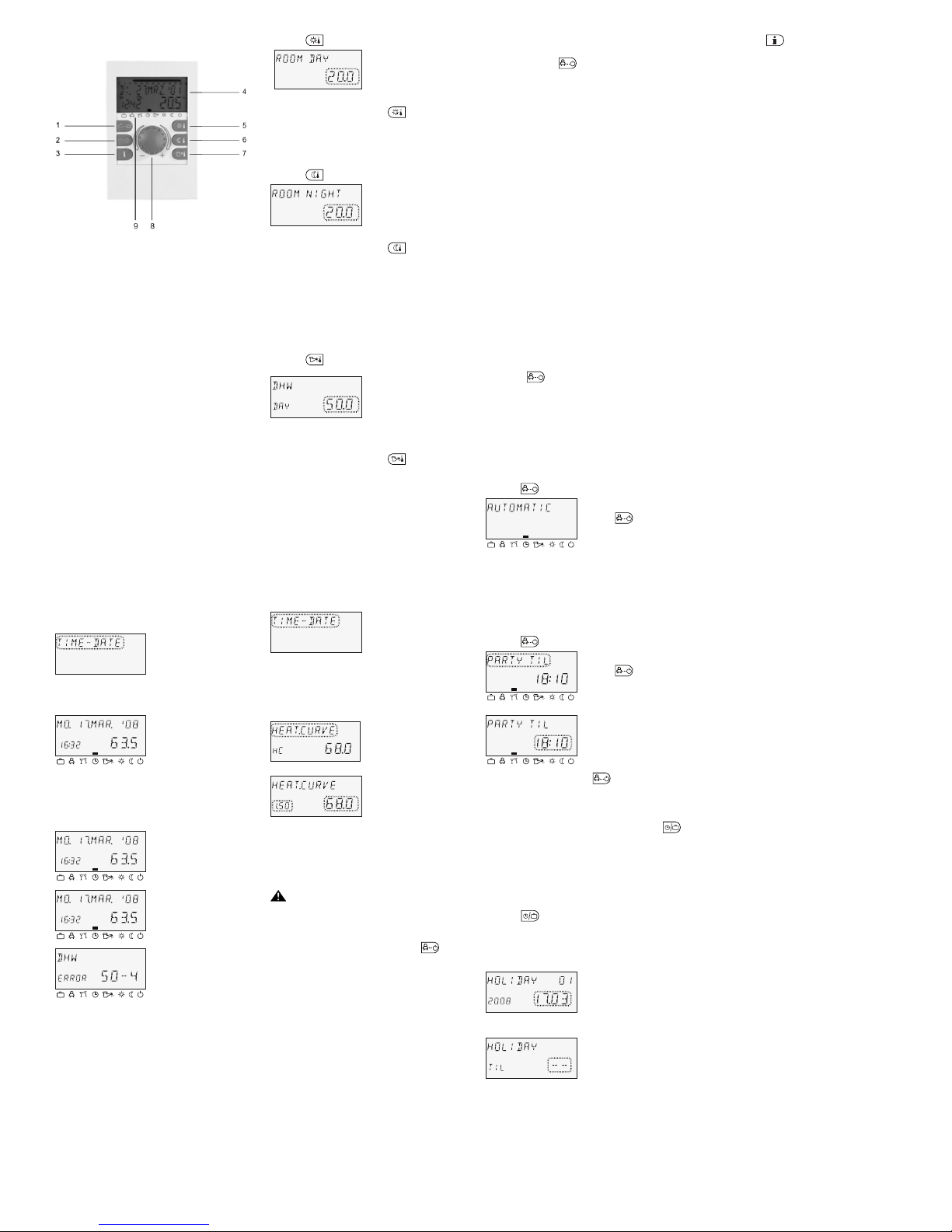
1 "Operating modes" button (basic display)
2 "Switching time programs"/"Holiday programs" button
3 "System information" button
4 Display
5 "Daytime room temperature" button
6 "Night-time room temperature" button
7 "Daytime hot-water temperature" button
8 Input button (press/turn)
9 Operating mode symbols (heating programs)
Pos: 2 /156-Honeywell/Kurzanleitungen/Eingabeknopf - Allgemeine Funkti onen @ 0\mod_120584738279 6_6.doc @ 2830
Input button (press/turn) – General functions
Selected setpoints and parameters can be changed with
the input button and then saved by pressing the button.
The various programs can be selected by turning the
input button.
Turning to the
right (+):
increases adjustment
Turning to the
left (–):
decreases adjustment
ð
Press: accepts the selected and
displayed value
ö
î
Press and hold: jumps to the
programming level (level
selection), jumps back to
the previous selection
ö
î
Pos: 3 /156-Honeywell/Kurzanleitungen/Blinkende Display-Anzeige @ 0\ mod_1205847454750_6.doc @ 2835
Flashing elements in the display
In these instructions, flashing elements in the display are
indicated as follows:
Pos: 4 /156-Honeywell/Kurzanleitungen/Grundanzeige @ 0\mod_1205847553312_ 6.doc @ 2840
Basic display
C
ÃÂÀÁ
Day of the week, date, time,
heat generator temperature
The mark (rectangle) over
the operating mode symbols
indicates the current
operating mode.
Pos: 5 /156-Honeywell/Kurzanleitungen/Sonderanzeigen @ 0\mod_12058476333 90_6.doc @ 2845
Special indicators
C
ÃÂÀÁ
Snowflake symbol:
System anti-freeze active
C
ÃÂÀÁ
Beach umbrella symbol:
Summer de-activation active
(heating switched off; hot
water by program)
Error message (e.g. hot
water) alternates with the
basic display: Contact a
heating specialist!
Pos: 6 /156-Honeywell/Kurzanleitungen/Tages-Raumtemperatur_(W andgeraet) @ 1\mod_120815609 0814_6.doc @ 10825
Setting daytime room temperature
Press the
button.
C
Change the temperature:
ð
Setting range: 5 to 30°C
Accept the change:
öî
or or automatically
after the set info time expires.
Pos: 7 /156-Honeywell/Kurzanleitungen/Nacht-Raumtemperatur_(W andgeraet) @ 1\mod_12081561 25236_6.doc @ 10840
Setting night-time room temperature
Press the
button.
C
Change the temperature:
ð
Setting range: 5 to 30°C
Accept the change:
ö
î
or or automatically
after the set info time expires.
NOTE: In operating mode 2, select the respec tive
heating circuit and confirm it by pr essing the
input button before setting the daytime or nighttime room temperature
Pos: 8 /156-Honeywell/Kurzanleitungen/Tages-Warmwassertemperatur_( Wandgeraet) @ 1\mod_12 08156158564_6.doc @ 10855
Setting daytime hot-water temperature
Press the
button.
C
Change the temperature:
ð
Setting range:
5°C to the maximum hotwater temperature
Accept the change:
öî
or or automatically
after the set info time expires.
Pos: 9 /156-Honeywell/Kurzanleitungen/Heizkurven @ 0\mod_1205848498796_6. doc @ 2865
Heating curves
With the heating curves, the heating power is adapted to
the building condition based on the respective outside
temperature.
Pos: 10 /156-Honeywell/Kurzanleitungen/Heizkurve_korrigier en_(Wandgeraet) @ 1\mod_1208161 159064_6.doc @ 10870
Correcting slope of heating curve
Entering the menu:
öî
for approx. 3 seconds
Select the heating circuit:
ð
HC = Direct heating circuit
MC1 = Mixed heating
circuit 1
MC2 = Mixed heating
circuit 2
Accept the change:
öî
Correct the characteristic
curve:
Room temperature too hot:
Reduce setting value
Room temperature too cold:
Increase setting value
Accept the change: öî or automatically after the set
info time expires. If necessary, call up additional heating
circuits and correct the slopes of the heating curves.
CAUTION
Corrections may only be carried out after a
sufficiently long period of steady conditions and in
small increments.
Finish (return to basic display): Press the
button.
Pos: 11 /156-Honeywell/Kurzanleitungen/Heizprogramme_(Wandgeraet) @ 1\mod_1208161203533_6. doc @ 10885
Heating programs
(
æ ç è é ê ë ì í
)
The following heating programs can be selected with the
input button after the button is pressed:
1. Short-term programs:
ABSENT TIL
ç
Brief interruption of heating operation in
case of absence.
PARTY TIL
è
Extended heating operation past the
regular lowering time.
2. Automatic programs:
AUTOMATIC
é
Automatic heating and lowering operation
by switching time program.
SUMMER
ê
Exclusively hot-water operation by
switching time program; heating switched
off, but frost protected.
3. Continuous programs:
HEATING
¾
Constant heating operation without time
limits.
RED.
HEATING
ì
Constant reduced heating operation
without time limits.
STANDBY
í
Frost-protected switch-off of heating and
hot water.
Pos: 12 /156-Honeywell/Kurzanleitungen/Programm_waehlen_(Wandgeraet) @ 1\mod_1208161235017_ 6.doc @ 10900
Selecting program
When the
button is pressed, the last selected
program flashes. All other programs can be selected with
the input button, whereby the marking (rectangle) above
the operating mode symbols indicates the respective
symbol.
The selected program is activated by then pressing the
input button.
Pos: 13 /156-Honeywell/Kurzanleitungen/Programm_waehlen_(Beispiel_Party) (Wandgeraet) @ 1\mod_120816126 6330_6.doc @ 10915
Example: Automatic program
Press the
button and select AUTOMATIC.
Accept the change:
öî
or
When a time program is selected, the respective
accompanying periods such as the return date
(HOLIDAY), return time (ABSENT TIL) or extended
heating mode (PARTY TIL) can be specified.
Example: Party program
Press the
button and select PARTY TIL.
Accept the change:
öî
or
Change the time:
ð
Accept the change:
öî
or
Pos: 14 /156-Honeywell/Kurzanleitungen/Urlaubsprogramme_(Wandgerae t) @ 1\mod_120816136043 9_6.doc @ 10930
4. Holiday programs
The holiday programs can be selected with the
button.
HOLIDAY
æ
Frost-protected switch-off or reduced
operation of heating during holidays. Hot
water is switched off, but frost protected.
Pos: 15 /156-Honeywell/Kurzanleitungen/Programm_waehlen_(Urlaub)(Wandgeraet ) @ 1\mod_1208161387017_6.doc @ 10945
Example: Holiday programs
Press the
button, select HOLIDAY and confirm with
î
.
Select holiday block (e.g. HOLIDAY 01) and confirm with
î
.
Change the year and date:
ð
Accept the change:
öî
Enter the date:
ð
Accept the change:
öî
Pos: 16 /156-Honeywell/Kurzanleitungen/Anlageinformationen_(W andgeraet) @ 1\mod_12081614 38361_6.doc @ 10960
System information
After pressing the
button, all system temperatures
and the operating conditions of all system components
can be queried one after another via the input button.
Press:
• System temperatures (setpoints)
Turn:
• System temperatures (actual values)
• Function and values of variable inputs
• Counter and consumption data
Heating circuit information, such as:
• Program type (HOLIDAY, ABSENT TIL, PARTY TIL,
AUTOMATIC etc.)
• Current switching time program (P1 or P1–P3 after
enable)
• Operating mode (daytime operation, lowering
operation, switch-off operation)
• Heating circuit depending on the device version (HC =
direct heating circuit, MC1 = mixed heating circuit 1,
MC2 = mixed heating circuit 2, DHW = hot-water
circuit)
• Status of the respective heating circuit pump (OFF-
ON)
• Status of the respective mixing motor (OPEN-STOP-
CLOS)
• Status of the heat generator (OFF-ON)
• Status and function of the variable outputs
NOTE: The system information appears in accordance
with the device version used.
Pos: 17 /156-Honeywell/Kurzanleitungen/Schaltzeitenprogrammierun g_(Wandgeraet) @ 1\mod_ 1208161779001_6.doc @ 10975
3 s
Page 2
Manufactured for and on behalf of the Environmental and
Combustion Controls Division of Honeywell Technologies
Sàrl, Ecublens, Route du Bois 37, Switzerland by its
Authorized Representative:
Automation and Control Solutions
Honeywell House
Arlington Business Park
Bracknell, Berks, RG12 1EB
Phone (44) 1344 656000
Fax (44) 1344 656644
http://honeywell.com/uk
Printed in Germany
All rights reserved. Subject to change without
notice.
EN2B-0227GE51 R0308
A
rt. 045 130 5574
–
0812 – 30
Switching time programming
Entering the "Switching times" level: Press the
button.
(For detailed information see the SDC/DHC operating
instructions, GE2H-0220)
Every setting value that flashes in the display is corrected
with the input button and accepted by pressing the
button. Pressing the
button jumps back to the
previous selection. Pressing the
button or waiting
the set info time jumps back to the basic display.
1. Selection of the circuit, reloading of
default programs, copying
Setting range: Direct heating circuit (HC), mixed
heating circuit 1 (MC1), mixed heating
circuit 2 (MC2), hot-water circuit (DHW),
default programs, copying heating
circuits
Continue:
öî
2. Selection of the switching time program
Prerequisite:
Parameter 02 in the "System Parameters" menu is P1–
P3.
Setting range: P1, P2, P3
Continue:
öî
C
0 2 4 6 8 12 14 16 18 20 22 24
3. Selection of weekday and heating cycle, copying
(block building)
Setting
sequence:
Mon. 1st cycle – Mon. 2nd cycle,
Tue. 1st cycle – Tue. 2nd cycle ... Sun.
2nd cycle, copy to individual days (Mon.,
Sun.), weekday block (1–5), weekend
block (6–7), entire week (1–7).
NOTE: If the second cycle is occupied, a third cycle is
available.
Continue:
öî
C
0 2 4 6 8 12 14 16 18 20 22 24
4. Start of heating (switch-on time)
Setting range: 0:00 to 24:00 hours
NOTE: The switch-on time is displayed in the top time
bar via a flashing segment.
Continue:
öî
C
0 2 4 6 8 12 14 16 18 20 22 24
5. End of heating (switch-off time)
Setting range: 0:00 to 24:00 hours
NOTE: The switch-off time is displayed in the top time
bar via a flashing segment.
Continue:
öî
C
0 2 4 6 8 12 14 16 18 20 22 24
6. Cycle temperature for the selected heating cycle
on selected weekday
Setting range: for heating circuits (HC, MC1, MC2):
5 to 30°C
for the hot-water circuit (DHW):
10 to 80°C (or the maximum hot-water
temperature)
CAUTION
If the desired daytime room temperature or hot-water
temperature is changed with the or
button, all associated cycle temperatures change by
the same value accordingly!
Continue:
öî
C
0 2 4 6 8 12 14 16 18 20 22 24
7. Selection of weekday and heating cycle,
copying (block building)
If necessary, select the next heating cycle or weekday as
described in Step 3 and program it accordingly.
Pos: 18 /156-Honeywell/Kurzanleitungen/Betrieb_von_digitalen_W andgeraeten @ 1\mod_12081 61855064_6.doc @ 10990
Operation of digital wall device SDW 30
Pos: 19 /156-Honeywell/Kurzanleitungen/Funktion (Wandgerät) @ 0\mod_1205851 410203_6.doc @ 2917
Pos: 19 /156-Honeywell/Kurzanleitungen/Funktion @ 1\mod_1208161933361_6. doc @ 11005
Function
The digital wall device SDW 30 can be connected to a
central controller (central device).
With a digital wall device, remote control of a central
device (e.g. from a living room), in addition to room
temperature detection, is possible. Settings can be
carried out for all the existing heating circuits.
The bus address of the wall device is used to specify the
heating circuit on which the room sensor (room
influence) is to act.
The selection of the address for the heating circuit to
which the SDW 30 is to be assigned (bus address)
occurs the first time an SDW 30 is connected to the bus
system.
Should the address be changed later on, the press and
turn button must be pressed and held when the wall
device is set into the socket until the bus address
appears in the display.
After the input has been confirmed, feedback of the
heating circuit (HC, MC1, MC2) and the central device
(CU) to which the digital wall device has been assigned is
output.
Assignment is carried out on the basis of the following
table:
Address CU address Assignment
11 10 CU 1 – Direct heating circuit
12 10 CU 1 – Mixed heating
circuit 1
13 10 CU 1 – Mixed heating
circuit 2
21 20 CU 2 – Direct heating circuit
22 20 CU 2 – Mixed heating
circuit 1
23 20 CU 2 – Mixed heating
circuit 2
31 30 CU 3 – Direct heating circuit
32 30 CU 3 – Mixed heating circuit 1
33 30 CU 3 – Mixed heating circuit 2
41 40 CU 4 – Direct heating circuit
42 40 CU 4 – Mixed heating
circuit 1
43 40 CU 4 – Mixed heating
circuit 2
51 50 CU 5 – Direct heating circuit
52 50 CU 5 – Mixed heating
circuit 1
53 50 CU 5 – Mixed heating
circuit 2
Caution
Double assignments of bus addresses are not
permissible and inevitably lead to errors in data
transmission and thus to faulty control behaviour of
the heating system.
Pos: 20 /156-Honeywell/Kurzanleitungen/Montage @ 1\mod_1208162032642_6.doc @ 11020
Installation
Installation location
The wall device is to be attached in a neutral
measurement location, i.e. that is representative of all
rooms, at a height of approx. 1.2 to 1.5 m. It is advisable
to select a partition wall of the coolest room used during
the day.
The wall device may not be attached:
• at locations in direct sunlight (take seasonal variations
into consideration)
• near devices that generate heat, such as te levisions,
refrigerators, wall lamps, radiators etc.
• to walls containing heating or hot-water pipes or
heated chimneys
• to exterior walls
• in corners or wall recesses, shelves or behind curtains
(insufficient air circulation)
• near doors leading to unheated rooms (external cold
influence)
• in front of unsealed flush-mounted boxes
Installation
Remove the front cover and secure the wall device at the
intended installation site using screws and plugs. Feed
the data bus cable required for the electrical connection
through the central break-out.
Electrical connection
Make the electrical connection to the 2-pole terminal
strip. Recommended connection cable: J-Y (ST) Y
2 x 2 x 0.6 mm
2
.
Caution
Do not switch connection terminals A and B!
After connecting the data bus cable and setting the bus
address, reattach the front cover.
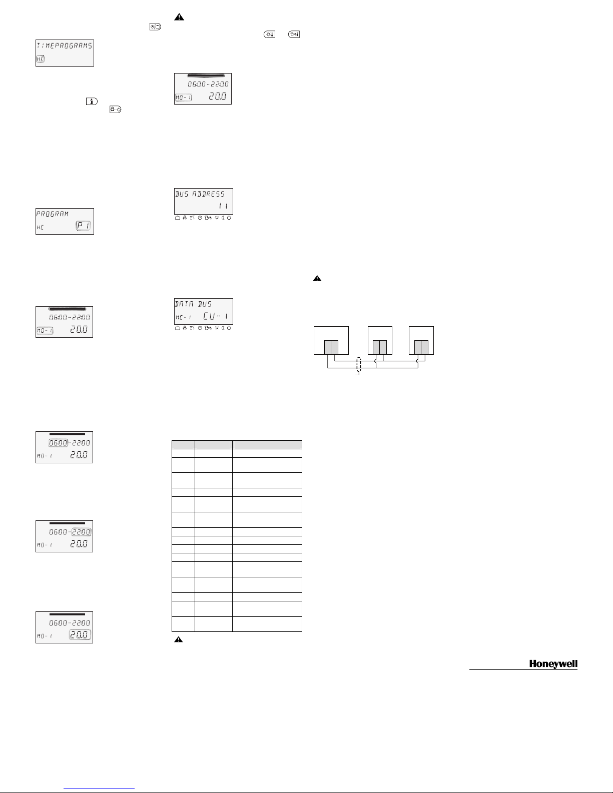
General wiring diagram
AB
SDC / DHC
a
AB
SDW 30
a
AB
SDW 30
a
bc d
Fig. 1: Connection of SDW 30 to central device
a Data bus b Data bus cable
(shielded)
c SDW 30 connected
to heating circuit 1
(direct heating circuit)
d Additional wall devices
connected to heating
circuit
===== Ende der Stückliste =====
===== Ende der Stückliste =====
 Loading...