

Page 1
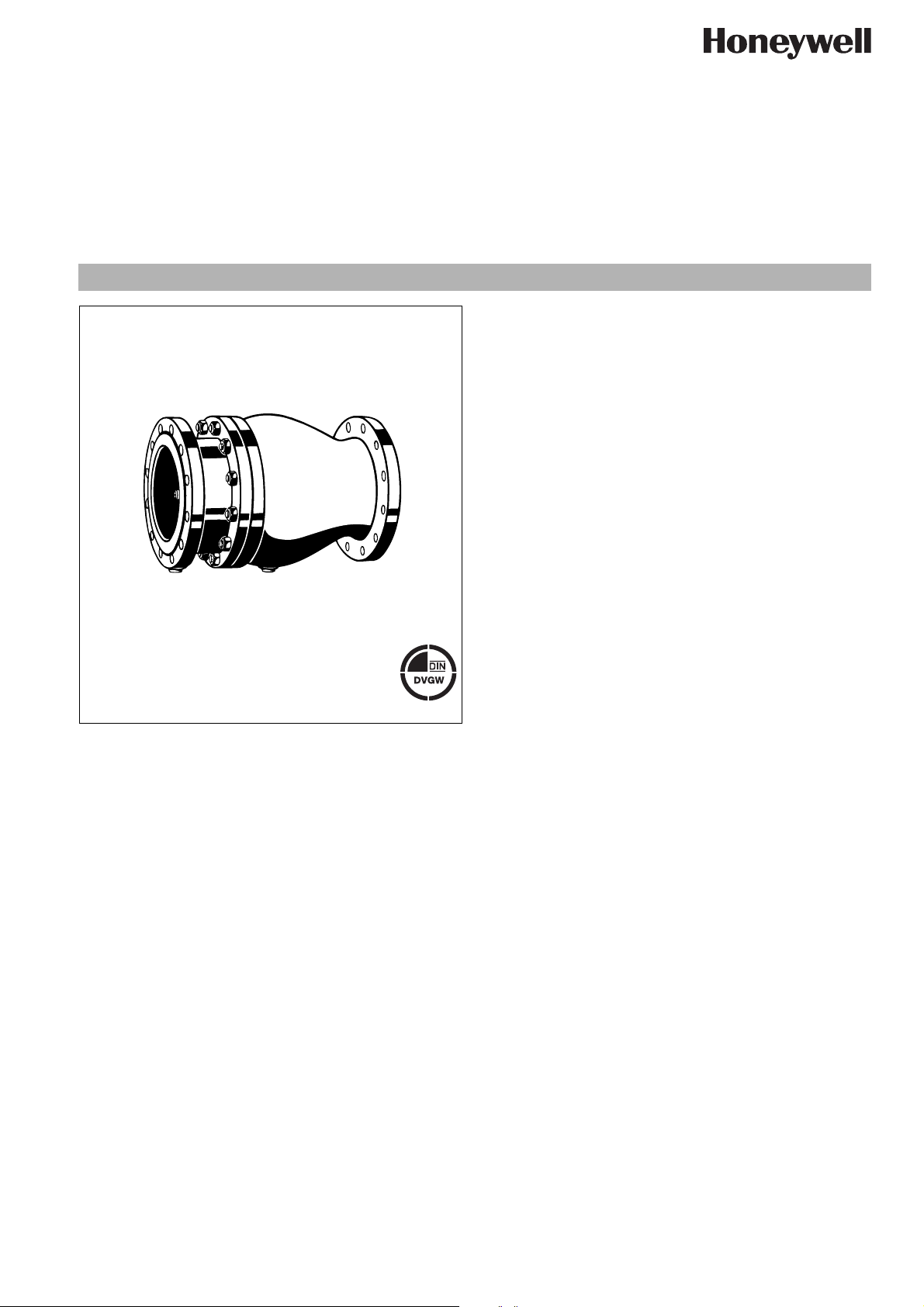
RV283P
Controllabel anti-pollution check valve with flanges
Product specification sheet
Application
Check valves are preferably for use as an independent means of
preventing reverse water flow and are for installing directly after a
water meter, but also for application in transfer pipes on district
water supply systems.
They can also be used for industrial, commercial and similar
systems where back pressure, back flow and back syphonage
must be prevented.
The types of safety devices required for these purposes are
specified in EN 1717.
Special Features
• DIN/DVGW-certified where applicable (for DN40-DN150)
• Universal application
• High temperature resistance
• Create no shock pressure loadings
• Powder coated inside and outside
• Meets KTW regulations for potable water
• Disc, spring and lip seal ring are exchangeable
CERT
• Low pressure loss
Construction
The check valve comprises:
• Housing with flanges
• Housing end casing with flanges
• Test and drain plugs
• Disc and disc guide
•Spring
• Disc lip seal ring
Materials
• Grey cast iron housing end and housing
o Powdercoated with:
High-performance polyamide (DN50 - DN100)
High-performance epoxy resin (DN125 - DN300)
• Stainless steel screws and nuts
• Stainless steel disc (red bronze for DN 40 and DN 50)
• Stainless steel spring
• EPDM for lip seal ring
EN0H-1203GE23 R0514 • Subject to change
Range of Application
Medium Drinking water
Inlet pressure max. 16.0 bar
Technical Data
Operating temperature 65 °C
Opening pressure approx. 0.05 bar
Connection size DN40 - DN300
http://ecc.emea.honeywell.com 1
Page 2

RV283P Controllabel anti-pollution check valve with flanges
Method of Operation
Spring loaded check valves have a moving seal disc which is
lifted off the seat by a greater or lesser amount depending on the
flow rate through the valve. If the flow falls towards zero, then the
spring pushes the disc back onto the seat and seals the
waterway.
To ensure continuing correct function it is recommended that
check valves be regularly checked and maintained (as specified
in EN 1717).
Options
RV283P-... A = With drilled flanges, PN16, ISO 7005-2,
EN 1092-1, DN40 - DN300,
EPDM lip seal ring
Connection size
Connection size R 40 50 65 80 100 125 150 200 250 300
Weight approx. kg9 11172129376278155180
Dimensions mm
L 180 200 240 260 300 350 400 500 600 700
37.5 36.5 89 107 111.5 131.5 149 163 186 218
L
1
∅F 150 165 185 200 220 250 285 340 405 460
∅D 150 165 185 200 220 250 285 345 420 475
1
Test and drain plugs R
-value m3/h 39 62 110 170 240 420 760 1400 2100 3000
k
vs
Nominal flow rate in m
3
/h
/4"
15.1 24.0 43.0 66.0 93.0 163.0 295.0 542.0 813.0 1162.0
1
/4"
1
/2"
1
/2"
1
/2"
3
/4"
3
/4"
3
/4"
3
/4"
3
/4"
at Δp = 0.15 bar
DIN/DVGW Registration No. NW - 6310 BU 0492 Approval not compulsory
2 http://ecc.emea.honeywell.com
EN0H-1203GE23 R0514 • Subject to change
Page 3

Installation Example
RV283P Controllabel anti-pollution check valve with flanges
10
5
15
bar
0
16
Installation Guidelines
• Install in horizontal pipework with test and drain plugs downwards
o This position is best for draining
• Install shutoff valves
o Shutoff valves provide optimal serviceability
• Ensure good access
o Simplifies maintenance and inspection
• Install right after water meter if applicable
o Protects against backflow from water systems
Flow Diagram
Typical Applications
Check valves of this type are suitable for use as a safety device
on water installations as well as for district water supply mains as
specified in EN 1717.
They can also be used for commercial, industrial or similar water
supply systems.
The following are some typical applications:
• In central water supply systems
• After a water meter
• As a safety device up to liquid category 2 of EN 1717
• Downstream of pumping installations
• Upstream of water heating installations
•In laundries
• In refineries
•In district heating systems
EN0H-1203GE23 R0514 • Subject to change
http://ecc.emea.honeywell.com 3
Page 4

RV283P Controllabel anti-pollution check valve with flanges
DN40, DN50, DN125 - DN30
1
2
4
3
4
3
DN65 - DN100
1
2
4
3
Spare Parts
Check valve RV283P, from 2000 onwards
No. Description Dimension Part No.
1 Valve disc guide DN40 5605800
DN50 5605900
DN65 0900376
DN80 0900377
DN100 0900378
DN125 0900379
DN150 0900380
DN200 0900381
DN250 0900382
DN300 0900383
2 Lip seal ring DN40 2238700
DN50 2238800
DN65 5350000
DN80 5350300
DN100 5350400
DN125 2070300
DN150 2067300
DN200 2238900
DN250 2239000
DN300 2239100
4
3
3 Hexagonal blanking DN40 - DN50 5726800
plug DN65 - DN100 2248700
DN125 - DN300 2591000
4 Seal ring DN40 - DN50
2166600
up to 06/2013
DN40 - DN50
0904122
from 07/2013
onwards
DN65 - DN100 5350500
DN125 - DN300 2698000
Automation and Control Solutions
Honeywell GmbH
Hardhofweg
74821 MOSBACH
GERMANY
Phone: (49) 6261 810
Fax: (49) 6261 81309
http://ecc.emea.honeywell.com
Manufactured for and on behalf of the
Environmental and Combustion Controls Division
of Honeywell Technologies Sàrl, Z.A. La Pièce 16,
1180 Rolle, Switzerland by its Authorised Representative Honeywell GmbH
EN0H-1203GE23 R0514
Subject to change without notice
© 2014 Honeywell GmbH
 Loading...