

Page 1
RV281
Controllable anti-pollution check valve EA type
with union connectors
Product specification sheet
Application
Check valves of this type are for use as an independent means
of preventing reverse water flow and for installing directly after a
water meter on central water supply systems.
They can also be used for industrial, commercial and similar systems where back pressure, back flow and back syphonage
must be prevented.
The classicfications of appliances to meet these requirements
are specified in EN 1717.
Special Features
• DIN/DVGW-approved
• Universal application
• Suitable for installation in any position
• Create no shock pressure loadings
• Union connectors simplify service
• Fully approved for noise level protection to class 1
• Meets KTW recommendations for potable water
•Low pressure loss
Construction
The check valve comprises:
1
• Housing with test and drain plugs (
test plugs only)
• Check valve insert
• Threaded or soldered union connectors
• Test and drain plugs
•Disc guide
•Spring
• Disc with lip seal ring
Materials
• Brass housing
• Brass union nuts
• Red bronze threaded union connectors (brass for 2")
• High grade synthetic material disc guide and disc
• NBR lip sealing ring
• Stainless steel spring
• High grade synthetic material blanking plugs
/2" device with
Range of Application
Medium Water, compressed air, petroleum, medi-
um and light fuel oils, kerosene, gasoline
with less than 15 % aromatic content.
Not suitable for gaseous mediums below
0.5 bar, steam, heavy oils and benzole.
Max. inlet pressure 16 bar
Technical Data
Operating temperature
Opening pressure approx. 0.05 bar
Connection size
Water up to 75 °C (short term up to 90 °C)
Compressed air and other mediumsup to
70 °C
1
/2“ - 2“
EN0H-1202GE23 R0206 y Subject to change without notice
www.honeywell.com 17
Page 2
RV281 Controllable anti-pollution check valve EA type
Method of Operation
Spring loaded check valves have a moving seal disc which is lifted off the seat by a greater or lesser amount depending on the
flow rate through the valve. If the flow falls towards zero, then the
spring pushes the disc back onto the seat and seals the waterway.
To ensure continuing correct function it is recommended that
check valves be regularly checked and maintained (as specified
in EN 1717).
Options
RV281-... A = With internal thread
RV281-... B = With soldered union connectors
Special Versions available on request
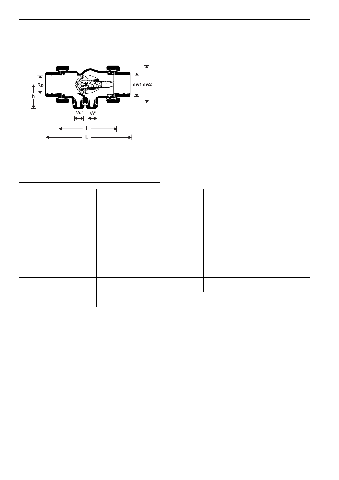
Connection size
Connection size Rp
1
/2"*
3
/4"1"1
1
/4"1
1
/2"2"
Connection size with
soldered unions
mm
15 22 28 35 42 54
Weight approx. kg 0.4 0.6 0.8 1.3 2.0 2.6
Dimensions mm
L 106 120 139 161 171 201
I60728595103125
h343440454757
sw 1243038465266
sw 2374652647688
Test and drain plug R
-value m3/h 4.5 9.1 17.0 28.0 38.0 60.0
k
vs
Nominal flow rate in m
3
/h
1
/4"*
1
/4"
1
/4"
1
/4"
1
/4"
1
at ∆p = 0.15 bar 2.3 3.1 7.7 10.8 15.5 25.2
DIN/DVGW Approval No. NW-6310 AT 2325
IfBt Designation P-IX 2614/I - -
* Test plug only
/4"
18 www.honeywell.com
EN0H-1202GE23 R0206 y Subject to change without notice
Page 3

Installation Example
RV281 Controllable anti-pollution check valve EA type
Installation Guidelines
• Install in horizontal pipework with test and drain plug downwards
o This position is best for draining
• Install shutoff valves
o Shutoff valves provide optimal serviceability
• Ensure good access
o Simplifies maintenance and inspection
• Install right after water meter if applicable
o Protects against backflow from water systems
Flow Diagram
Typical Applications
Check valves of this type are suitable for use as a safety device
on water installations as specified in EN 1717.
They can be used within the scope of their specification.
The following are some typical applications:
• In central water supply systems
• After a water meter
• As a safety device up to liquid category 2 of EN 1717
• Downstream of pumping installations
• Upstream of water heating installations
EN0H-1202GE23 R0206 y Subject to change without notice
www.honeywell.com 19
Page 4

RV281 Controllable anti-pollution check valve EA type
Spare Parts
Inlet check valve RV281, from 1984 onwards
No. Description Dimension Part No.
1
c Disc guide
/2" 5534900
3
/4" 5535100
1" 5531500
11/4" 5535300
1
/2" 5535500
1
2" 5535700
d Spring
1
/2" 2061400
3
/4" 2061500
1" 2061600
1
/4" 2061700
1
1
/2" 2062000
1
2" 2062400
e Valve disc complete
1
/2" 0900356
3
/4" 0900357
1" 0900358
1
/4" 0900359
1
1
1
/2" 0900360
2" 0900361
f Hexagon-plug all S06M-1/4
1
with O-ring R
/4"
(5 pcs.)
1
g Seal washer
/2" 5351200
3
/4" 5351300
1" 5018100
11/4" 5957600
1
/2" 5163000
1
2" 5163100
Automation and Control Solutions
Honeywell GmbH
Hardhofweg
D-74821 Mosbach
Phone: (49) 6261 810
Fax: (49) 6261 81309
http://europe.hbc.honeywell.com
www.honeywell.com
Manufactured for and on behalf of the
Environmental and Combustion Controls Division
of Honeywell Technologies Sàrl, Ecublens, Route
du Bois 37, Switzerland by its Authorised Representative Honeywell GmbH
EN0H-1202GE23 R0206
Subject to change
© 2006 Honeywell GmbH
 Loading...