

Page 1
RV181
Einbauanleitung • Installation instructions
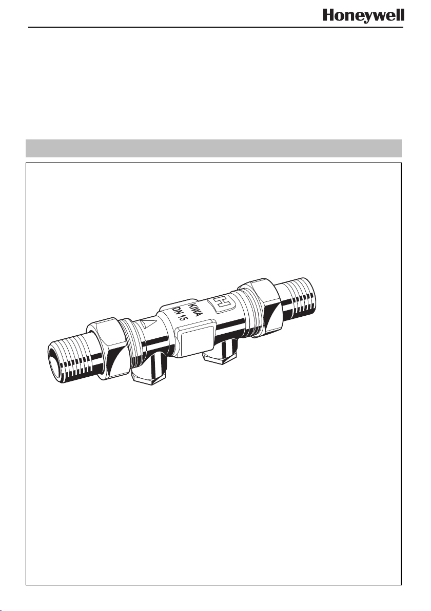
Rückflussverhinderer
Non return valve
EB-RV181 Rev. A
Page 2
D
1. Sicherheitshinweise
1. Beachten Sie die Einbauanleitung.
2. Benutzen Sie das Gerät
• bestimmungsgemäß
• in einwandfreiem Zustand
• sicherheits- und gefahrenbewusst
3. Beachten Sie, dass das Gerät ausschließlich für den in
dieser Einbauanleitung genannten Verwendungsbereich
bestimmt ist. Eine andere oder darüber hinausgehende
Benutzung gilt als nicht bestimmungsgemäß.
4. Beachten Sie, dass alle Montagearbeiten nur durch autorisiertes Fachpersonal ausgeführt werden dürfen.
5. Lassen Sie Störungen, welche die Sicherheit beeinträchtigen können sofort beseitigen.
2. Funktionsbeschreibung
Der Rückflussverhinderer ist nach DIN EN 1717 eine Sicherungsarmatur und verhindert ein Rückdrücken, Rückfließen
und Rücksaugen von verunreinigtem Wasser in die Versorgungsleitung, in fremde Anlagen oder andere Anlagenteile.
Der Rückflussverhinderer sichert die Versorgungsleitung ab.
Der federbelastete Rückflussverhinderer verfügt über einen
beweglichen Dichtkegel, der sich entsprechend dem jeweiligen Volumenstrom mehr oder weniger vom Ventilsitz abhebt.
Geht der Volumenstrom gegen Null, so wird der Dichtkegel
durch die Federkraft wieder auf den Ventilsitz zurückgeführt
und liegt dort dicht auf.
3. Verwendung
Medium Wasser
Flüssigkeitskategorie 2 (keine gefährdende Stoffe)
4. Technische Daten
Einbaulage waagrecht mit Prüfschrauben nach
unten
Betriebsdruck max. 16 bar
Betriebstemperatur max. 70°C (kurzzeitig bis 90°C)
Anschlussgrößen 1/2" bis 2" (Gewindetülle, Löttülle)
ø15 und ø22 (Klemmringver-
schraubung)
5. Lieferumfang
Der Rückflussverhinderer besteht aus:
• Gehäuse
• Anschlussfittings (Variante A,B und K)
• Einsteckrückflussverhinderer (DVGW geprüft)
• Prüfschrauben mit Dichtring
6. Montage
6.1 Einbau
Beim Einbau müssen die Einbauanleitung, die örtlichen Vorschriften sowie die allgemeinen Richtlinien beachtet werden.
Der Einbauort muss frostsicher und gut zugänglich sein.
Vor und nach dem Rückflussverhinderer müssen Absperrarmaturen eingebaut werden.
6.2 Montageanleitung
1. Rohrleitung gut durchspülen.
2. Absperrarmaturen ein- und ausgangsseitig schließen.
3. Rückflussverhinderer einbauen.
• Einbau in waagrechte Rohrleitung mit Prüfschrauben
nach unten.
• Durchflussrichtung beachten (Pfeilrichtung).
• Einbau spannungs- und biegemomentfrei.
4. Absperrarmaturen ein- und ausgangsseitig langsam öffnen.
7. Inbetriebnahme
Es sind keine Inbetriebnahmearbeiten durchzuführen
i
8. Instandhaltung
Wir empfehlen einen Wartungsvertrag mit einem
Installationsunternehmen abzuschließen
i
Entsprechend DIN 1988, Teil 8 sind folgende Maßnahmen
durchzuführen:
8.1 Wartung
Intervall: einmal jährlich
Durchführung durch ein Installationsunternehmen
i
Durchführung durch den Betreiber
1. Absperrarmatur eingangsseitig schließen.
VORSICHT!
Prüfschrauben erst öffnen, wenn Absperrarmatur
eingangsseitig geschlossen wurde!
2. Eingangsseitige Prüfschraube öffnen.
Bis zur Druckentlastung tritt etwas Wasser aus der Prüfschraube aus.
VORSICHT!
Tropft oder läuft Wasser beständig weiter ☞ Ein-
steckrückflussverhinderer verschmutzt oder defekt!
Rückflussverhinderer ersetzen.
3. Prüfschraube wieder schließen.
4. Absperrarmatur eingangsseitig langsam öffnen.
9. Entsorgung
Der Rückflussverhinderer besteht aus:
• Messing
•Stahl
• Kunststoff
Die örtlichen Vorschriften zur ordnungsgemäßen
Abfallverwertung bzw. Beseitigung beachten!
10. Störung/Fehlersuche
Störung Ursache Behebung
kein oder zuwenig Wasserdruck
Absperrarmaturen vor
oder nach
Rückflussverhinderer
nicht ganz geöffnet
Einsteckrückflussverhinderer defekt
Absperrarmaturen
ganz öffnen
Funktion Rückflussverhinderer überprüfen (☞ Kapitel 8.1)
oder ggf. ersetzen
MU1H-1228GE23 R0205 2 Honeywell GmbH
Page 3

GB
1. Safety Instructions
1. Follow the installation instructions.
2. Use the appliance
• according to its intended use
• in good condition
• with due regard to safety and risk of danger
3. Note that the appliance is exclusively for use in the applications detailed in these installation instructions. Any other use will not be considered to comply with requirements.
4. All assembly operations should be carried out by competent and authorised personnel.
5. Immediately rectify any malfunctions which may influence
safety.
2. Functional description
The non return valve is a safety device in accordance with
DIN EN 1717 to protect systems against back pressure, back
flow and back syphonage of non-potable water into service
pipe, plants and equipments.
The non return valve protected the service pipe.
The spring loaded non return valve has a moving seal disc
which is lifted off the seat by a greater or lesser amount depending on the flow rate through the valve. If the flow falls
towards zero, then the spring pushes the disc back onto the
seat and seals the waterway.
3. Application
Medium Water
Liquid category 2 (no hazardous materials)
4. Technical data
Installation position horizontal pipework with test plugs
Admission pressure max. 16 bar
Operating pressure max. 70°C (short term 90°C)
Connection sizes 1/2" to 2" (threaded and soldering con-
5. Scope of delivery
The non return valve consists of:
• Housing
• Connections (Design A,B and K)
• Non return valve cartridge (DVGW approved)
• Test plugs with sealing ring
6. Assembly
6.1 Installation
It is necessary during installation to follow the installation instructions, to comply with local requirements and to follow the
codes of good practice.
• The installation location should be protected against frost
and be easily accessible.
Shut off valves should be fitted on each side of the non return
valve.
6.2 Assembly instructions
1. Thoroughly flush pipework.
2. Close shut off valves on inlet and outlet.
directed downwards
nections)
ø15 und ø22 (compression connection)
3. Install non return valve.
• Install in horizontal pipework with test plugs directed
downwards.
• Note flow direction (indicated by arrow).
• Install without tension or bending stresses.
4. Slowly open shut off valves on inlet and outlet.
7. Commissioning
• No commissioning work are required
i
8. Maintenance
We recommend a planned maintenance contract
with an installation company
i
In accordance with DIN 1988, part 8; the following measures
must be taken:
8.1 Inspection
Frequency: once annually
To be carried out by an installation company
i
To be carried out by the operator
1. Close shut off valve on inlet.
CAUTION!
Only open test plug if shut off valve on inlet has been
closed!
2. Open test plug in inlet.
Until pressure relief some water will emit from test plug.
CAUTION!
Water drips or keeps running continues ☞ Non
return valve cartridge is contaminated or worn!
Replace non return valve!
3. Close test plug on inlet.
4. Slowly open shut off valve on inlet.
9. Disposal
The non return valve consists of:
•Brass
•Steel
• Plastic
Observe the local requirements regarding correct
waste recycling/disposal!
10. Troubleshooting
Disturbance Cause Remedy
Too little or no
water pressure
Shut off valves up- or
downstream of the Y
strainer are not fully
open
Non return valve cartridge is faulty
Open the shut off
valves fully
Check function non
return valve (☞
chapter 8.1) or
replace
Honeywell GmbH 3 MU1H-1228GE23 R0205
Page 4

Automation & Control Solutions
Honeywell GmbH Phone: (49) 6261 810
Hardhofweg Fax: (49) 6261 81309
D-74821 Mosbach www.honeywell.com
MU1H-1228GE23 R0205
 Loading...