

Page 1
Characteristic
Parameter
LV (Low Voltage)
HV (High Voltage)
Supply voltage
5 ±0.5 Vdc
10 Vdc to 30 Vdc
Supply current
20 mA max.
32 mA max.
Supply current (during output to ground short)
25 mA max.
47 mA max.
Output
0.5 V to 4.5 V ratiometric
0.5 V to 4.5 V non-ratiometric
Output signal delay
4 ms typ.
Overvoltage protection
10 Vdc
Reverse polarity protection
-10 Vdc
-30 Vdc
Output to ground short circuit protection
continuous
Output load resistance (pull down to ground)
10 kOhm
EMI:
radiated immunity
conducted immunity
100 V/m from 200 MHz to 1000 MHz per ISO11452-2
100 mA BCI per ISO11452-4
from 1 MHz to 200 MHz
100 mA BCI per ISO11452-4
from 1 MHz to 400 MHz
EMC
exceeds CE requirements
Operating temperature range
-40 °C to 125 °C [-40 °F to 257 °F]
Storage temperature range
-40 °C to 125 °C [-40 °F to 257 °F]
Ingress protection
IP67 according to DIN 40050
Expected life
35 M cycles
Media compatibility
heavy transportation fluids
Housing material
PBT plastic
Shock
50 G peak
Vibration
20 G peak tested from 10 Hz to 2000 Hz
Resolution
12 bit
Termination
AMP super seal connector
Mechanical end stop
no
Approvals
CE
22,0
[0.87]
26,0
[1.02]
9,5
[0.37]
5,35 DIA.
[0.21]
37
[1.46]
55
[2.17]
5,9
[0.23]
8,3
[0.33]
15,50 DIA.
[0.61]
4,60
[0.18]
13,8
[0.54]
15,6
[0.61]
4,12
[0.16]
25
[0.98]
36,4
[1.43]
0
A
C
B
Pin 1
Pin 2
Pin 3
2,0 DIA.
[0.078]
6 DIA.
[0.24]
32,0 DIA.
[1.25]
0
/2
0
/2
RTYXXXXXXXX
YYDDMMSSSS
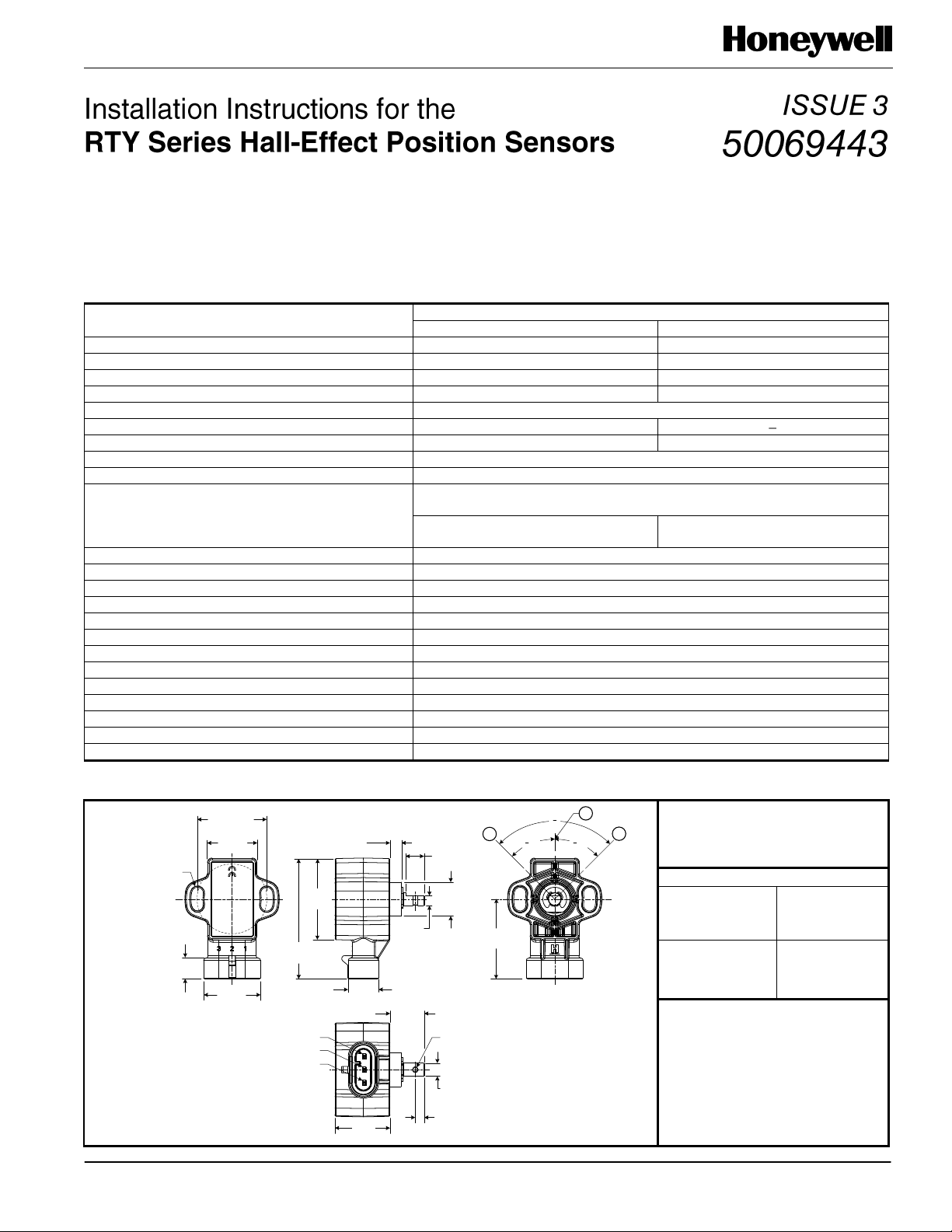
A = Left output: 0.5 Vdc
B = Zero reference
C = Right output: 4.5 Vdc
Pinout
N
(North
American)
E
(European)
Pin 1 = VCC
Pin 2 = GND
Pin 3 = Output
Pin 1 = GND
Pin 2 = VCC
Pin 3 = Output
NOTICE
Ferrous or magnetic material
within a 75 mm [2.95 in] radius
from sensor center may affect
sensor performance.
GENERAL INFORMATION
The RTY Series uses a magnetically biased, Hall-effect
integrated circuit (IC) to sense rotary movement of the actuator
shaft over a set operating range. Rotation of the actuator shaft
changes a magnet’s position relative to the IC. The resulting
flux density change is converted to a linear output.
Table 1. Specifications
MOUNTING INFORMATION
Mount the sensor using the two easily accessible mounting
holes and non-magnetic stainless steel M5 screws with flat
washers. Mounting screw tightening torque is 2,5 N m
±0,5 N m [22.1 in lb ±4.4 in lb]. In harsh applications, treat the
screw threads with a suitable thread locking compound.
Figure 1. Mounting Dimensions (For Reference Only: mm/[in].)
Sensing and Control
Page 2
RTY Series
Issue 3 50069443
Sensing and Control
Honeywell
1985 Douglas Drive North
Golden Valley, MN 55422
www.honeywell.com
50069443-3-EN
October 2012
Copyright © 2012. Honeywell International Inc. All rights reserved.
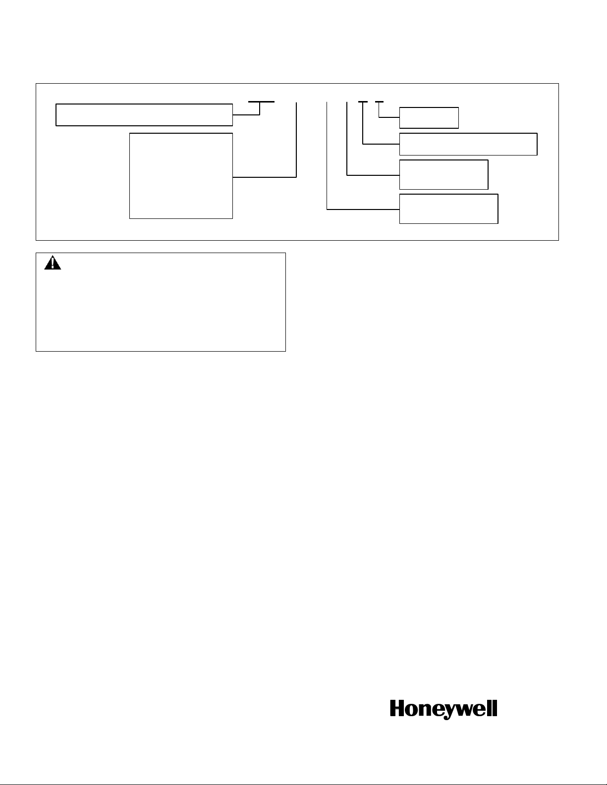
RTY _ _ _ _ _ _ A X
Product Series
RTY = Hall-Effect Rotary Position Sensor
Pinout Style
E = European
N = North American
Sensing Range Angle
050 = 50° (±25°)
060 = 60° (±30°)
070 = 70° (±35°)
090 = 90° (±45°)
120 = 120° (±60°)
180 = 180° (±90°)
270 = 270° (±135°)
360 = 360° (±180°)
Supply Voltage
LV = 5 Vdc
HV = 10 Vdc to 30 Vdc
Output Type
A = 0.5 Vdc (left), 4.5 Vdc (right)
Lever
X = No lever
PERSONAL INJURY
DO NOT USE these products as safety or emergency stop
devices or in any other application where failure of the
product could result in personal injury.
Failure to comply with these instructions could result in
death or serious injury.
Figure 2. Nomenclature and Order Guide
WARRANTY/REMEDY
Honeywell warrants goods of its manufacture as being free of
defective materials and faulty workmanship. Honeywell’s
standard product warranty applies unless agreed to otherwise
by Honeywell in writing; please refer to your order
acknowledgement or consult your local sales office for specific
warranty details. If warranted goods are returned to Honeywell
during the period of coverage, Honeywell will repair or replace,
at its option, without charge those items it finds defective. The
foregoing is buyer’s sole remedy and is in lieu of all other
warranties, expressed or implied, including those of
merchantability and fitness for a particular purpose. In no
event shall Honeywell be liable for consequential, special,
or indirect damages.
While we provide application assistance personally, through
our literature and the Honeywell web site, it is up to the
customer to determine the suitability of the product in the
application.
Specifications may change without notice. The information we
supply is believed to be accurate and reliable as of this printing.
However, we assume no responsibility for its use.
SALES AND SERVICE
Honeywell serves its customers through a worldwide network
of sales offices, representatives and distributors. For
application assistance, current specifications, pricing or name
of the nearest Authorized Distributor, contact your local sales
office or:
E-mail: info.sc@honeywell.com
Internet: www.honeywell.com/sensing
Phone and Fax:
Asia Pacific +65 6355-2828
+65 6445-3033 Fax
Europe +44 (0) 1698 481481
+44 (0) 1698 481676 Fax
Latin America +1-305-805-8188
+1-305-883-8257 Fax
USA/Canada +1-800-537-6945
+1-815-235-6847
+1-815-235-6545 Fax
Page 3

Hall-Effect Rotary Position
Sensors Line Guide
Round and round the globe, it’s Honeywell. So trust Honeywell
Sensing and Control (S&C) for your Hall-effect rotary position
sensor needs. These sensors vary output voltage or current in
response to changes in a magnetic field — using a magnetically
biased Hall-effect integrated circuit (IC) to sense rotary
movement of the actuator shaft. The rotation of the shaft changes
the IC’s position to the magnets, and then detects the change in
FEATURES
HALL-EFFECT ROTARY POSITION
SENSORS
RTY Series.
Features: 35 M cycle product life
• Solid-state Hall-effect technology
• Rugged IP67-sealed package with
integral connector • Automotive-grade
EMI/EMC testing, integrated reverse
polarity, and short circuit • Industrystandard AMP termination, 32 mm
mounting pitch, North American and
European pinout styles, and compact
package • Eight sensing ranges up to
360° • Low voltage and high voltage
versions
Benets: Angle monitoring in harsh
transportation and industrial applications
at a competitive cost. 12 M cycle product
life provides long life in the application.
Solid-state Hall-effect technology provides
non-contact operation, long service
life, low torque actuation and reduces
worn-out mechanisms. IP67 sealing and
integral connector allows for use in harsh
environments. EMI/EMC testing, reverse
polarity and short circuit provide protection
against installation errors and frequencies
in the environment. Industry standard
termination, mounting pitch and pinout
provide drop-in replacement for existing
applications. Choice of sensing ranges
provides flexibility in multiple applications,
allowing OEMS the range of travel needed
for the application. Potential applications
include position and movement detection of
pedals, throttles, gear shift, levers, steering,
linkages, and hitches (trucks, buses,
off-road vehicles, industrial/construction/
agricultural vehicles and equipment,
cranes); suspension displacement/kneeling
(buses, trucks); tilt/trim position (boat
engines, tilling equipment), as well as
industrial valve and HVAC damper control,
and irrigation pivot control
RPN Series.
Features: Solid-state Hall-effect
technology • 30 M cycle product life
• Eight sensing ranges up to 360°
• Reverse polarity, short circuit and EMC
protection • Choice of operating ranges,
outputs, and levers • IP67- or IP69K-
sealed package with integral connector
Benets: Long service life, low torque
actuation, and reduced mechanism wearout. Enhanced resistance to damage from
incorrect wiring and electrical noise. Wide
choice of sensing ranges provides range
of travel for most applications; tolerant
to overtravel. Output choices provide
flux density. The output of the IC is converted to a linear output
up to 360 degrees of travel. Honeywell S&C seals the IC together
with conditioning and protection circuitry and two permanent
magnets in a rugged package featuring enhanced reliability.
What’s more, our non-contacting approach to Hall-effect rotary
position applications provides longer-life solutions that excel in
most harsh environments.
application flexibility. Sealed package
with integral connector for durability.
Often ideal for detecting position and
movement of potential applications such
as pedals, throttles, gear shift levers,
linkages, suspension and hitches in trucks,
offroad vehicles, cranes and construction/
agricultural/industrial equipment.
HRS100 Series.
Features: Solid-state Hall-effect
technology • 10 M cycle product life
(typical) • Two sensing ranges • Choice of
termination
Benets: Use of magnetically coupled
technology in place of a mechanical wiper
assembly provides long life and a costeffective solution for harsh environments
that include temperature, vibration, dither,
moisture and dirt. Non-contact operation,
long service life, low torque actuation
and reduced wear-out of mechanisms.
Potential applications include position and
movement detection of pedals, throttles,
gear shift, levers, steering, linkages, and
hitches (off-road vehicles and industrial/
construction/agricultural vehicles/
equipment), tilt/trim position (boat engines),
and industrial material handling equipment
(forklifts, robotics)
continued on page 3
Page 4

Hall-Effect Rotary Position Sensors Line Guide
More are turning to
Honeywell, for more value.
Honeywell S&C RTY and
RPN Series Hall-effect rotary
position sensors respond
to the presence or to the
interruption of a magnetic
field, using a solid-state
Hall-effect IC to sense rotary
movement of the actuator
shaft and then producing a
proportional output. The IC,
circuitry and magnets are
galvanized with an integral
connector — more than a
match for the most unforgiving
conditions. The HRS100 Series
uses magnetically-coupled
technology in place of a
mechanical wiper assembly
which provides long life and
a cost-effective solution for
harsh environments.
These sensors are often ideal
for potential transportation
applications, such as throttle
and speed position and
control, inboard lever control,
foot pedal, gearshift, steering,
lever, linkage, seat, mirror, tilt
and manipulator arm position.
Hall-Effect Rotary
Position Sensors
RTY Series
Sensing range
Redundant version no
Input voltage
Output
Input current
Operating temperature range -40 °C to 125 °C [-40 °F to 257 °F]
Connector AMP super seal
Life 35 M cycles
EMI/EMC
Housing material PBT plastic
Dimensions 55 mm L x 43 mm W x 41 mm H [2.17 in L x 1.69 in W x 1.61 in H]
50° (±25°), 60° (±30°), 70° (±35°), 90° (±45°), 120° (±60°), 180° (±90°),
270° (±135°), 360° (±180°)
low voltage: 5 Vdc ±0.5 Vdc
high voltage: 10 Vdc to 30 Vdc
low voltage: 0.5 V to 4.5 V ratiometric
high voltage: 0.5 V to 4.5 V non-ratiometric
low voltage: 20 mA max.; during output to ground short, 25 mA max.
high voltage: 32 mA max.; during output to ground short, 47 mA max.
• EMI radiated immunity: 100 V/m from 200 MHz to 1000 MHz per ISO11452-2
• EMI conducted immunity:
- low voltage: 100 mA BCI per ISO11452-4 from 1 MHz to 200 MHz
- high voltage: 100 mA BCI per ISO11452-4 from 1 MHz to 400 MHz
• EMC: exceeds CE requirements
Other benefits include:
360-degree operating range
with multi-turn allowable
rotation, low torque actuation
and greatly reduced wearout mechanisms, enhanced
resistance to damage from
incorrect wiring and electrical
noise, wide operating
angle tolerant to overtravel,
integrated reverse polarity,
short circuit and EMC
protection.
2 www.honeywell.com/sensing
Page 5

Hall-Effect Rotary
Position Sensors
RPN Series HRS100 Series
Sensing range
Redundant version yes no
Input voltage 5 Vdc, 8 to 30 Vdc, 10 Vdc to 30 Vdc 5 Vdc ±10%
Output
Input current 20 mA max. 5 mA typ.
Operating temperature range -40 °C to 125 °C [-40 °F to 257 °F] -40 °C to 85 °C [-40 °F to 185 °F]
Connector
Life 30 M cycles 10 M cycles
EMI/EMC EMC: 200 V/m ISO 11452-3 EMI: 30 V/m, 10 kHz to 1000 MHz at 3 m
Housing material PA66 plastic metal
Dimensions
50° (±25°), 60° (±30°), 70° (±35°), 90° (±45°), 120° (±60°),
180° (±90°), 270° (±135°), 360° (±180°)
0.25 V to 4.75 V, 0.5 V to 4.5 V, 1 V to 9 V, 3 V to 5 V, 4.5 V to
0.5 V, 4.75 V to 0.25 V, 4 mA to 20 mA, 20 mA to 4 mA
AMP 1-1419168-1, AMP Superseal 282087-1,
Deutsch DT04-3P
63 mm L x 38,8 mm W x 56 mm H
[2.48 in L x 1.53 in W x 2.20 in H]
90° ±2°, 180° ±2°
5% to 95% of applied Vdd, approx. (programmable)
(output ratiometric to supply)
solder lug, flying wire leads
32,27 mm [1.3 in] H x 27,79 mm [1.1 in] W
Page 6

Warranty. Honeywell warrants goods of
its manufacture as being free of defective
materials and faulty workmanship.
Honeywell’s standard product warranty
applies unless agreed to otherwise by
Honeywell in writing; please refer to your
order acknowledgement or consult your
local sales office for specific warranty
details. If warranted goods are returned to
Honeywell during the period of coverage,
Honeywell will repair or replace, at its
option, without charge those items it finds
defective. The foregoing is buyer’s sole
remedy and is in lieu of all warranties,
expressed or implied, including those
of merchantability and tness for a
particular purpose. In no event shall
Honeywell be liable for consequential,
special, or indirect damages.
While we provide application assistance
personally, through our literature and
the Honeywell web site, it is up to the
customer to determine the suitability of the
product in the application.
Specifications may change without notice.
The information we supply is believed to
be accurate and reliable as of this printing.
However, we assume no responsibility for
its use.
For more information about Sensing and
Control products, visit www.honeywell.
com/sensing or call +1-815-235-6847
Email inquiries to info.sc@honeywell.com
Sensing and Control
Automation and Control Solutions
Honeywell
1985 Douglas Drive North
Golden Valley, MN 55422 USA
+1-815-235-6847
www.honeywell.com/sensing
005892-4-EN IL50 GLO
October 2012
Copyright © 2012 Honeywell International Inc. All rights reserved.
Page 7

RTY Series
Hall-Effect Rotary
Position Sensors
FEATURES AND BENEFITS (=competitive differentiator)
POTENTIAL APPLICATIONS
DESCRIPTION
The RTY Series Hall-Effect Rotary Position Sensors provide
angle monitoring in harsh transportation and industrial
applications at a competitive cost.
These products use a magnetically biased, Hall-effect
integrated circuit (IC) to sense rotary movement of the actuator
shaft over a set operating range. Rotation of the actuator shaft
changes a magnet’s position relative to the IC. The resulting
flux density change is converted to a linear output.
The IC, together with conditioning and protection circuitry, and
the permanent magnet, is sealed in an IP67-qualified rugged
package for durability in most harsh environments.
35 M cycle product life: Provides long life in the
application
Solid-state Hall-effect technology: Provides non-contact
operation, long service life, low torque actuation and
reduces worn-out mechanisms
Rugged IP67-sealed package with integral connector:
Allows for use in harsh environments
Automotive-grade EMI/EMC testing, integrated reverse
polarity, and short circuit: Provides protection against
installation errors and frequencies in the environment
Industry-standard AMP termination, 32 mm mounting
pitch, North American and European pinout styles, and
compact package: Provide drop-in replacement
Eight operating ranges up to 360°: Provides flexibility in
multiple applications, allowing OEMs the range of travel
needed for the application
Eight operating ranges (50°, 60°, 70°, 90°, 120°, 180°, 270°
and 360°) are tolerant to over-travel and allow use in most
common applications. Low voltage and high voltage versions
cover an input voltage range of 4.5 Vdc to 30 Vdc.
Most applications require no lever, and no brackets are
necessary.
Honeywell’s industry-leading capabilities in research and
development provide the customer with known quality and
support.
Transportation:
Position and movement detection of pedals, throttles, gear
shift, levers, steering, linkages, and hitches (trucks, buses,
off-road vehicles, industrial/construction/agricultural
vehicles and equipment, cranes)
Suspension displacement/kneeling (buses, trucks)
Tilt/trim position (boat engines, tilling equipment)
Industrial:
Valve control
HVAC damper control
Irrigation pivot control
Page 8

RTY Series
Characteristic
Parameter
LV (Low Voltage)
HV (High Voltage)
Supply voltage
5 ±0.5 Vdc
10 Vdc to 30 Vdc
Supply current
20 mA max.
32 mA max.
Supply current (during output to ground short)
25 mA max.
47 mA max.
Output
0.5 V to 4.5 V ratiometric
0.5 V to 4.5 V non-ratiometric
Output signal delay
4 ms typ.
Overvoltage protection
10 Vdc
Reverse polarity protection
-10 Vdc
-30 Vdc
Output to ground short circuit protection
continuous
Output load resistance (pull down to ground)
10 kOhm
EMI:
radiated immunity
conducted immunity
100 V/m from 200 MHz to 1000 MHz per ISO11452-2
100 mA BCI per ISO11452-4
from 1 MHz to 200 MHz
100 mA BCI per ISO11452-4
from 1 MHz to 400 MHz
EMC
exceeds CE requirements
Operating temperature range
-40 °C to 125 °C [-40 °F to 257 °F]
Storage temperature range
-40 °C to 125 °C [-40 °F to 257 °F]
Ingress protection
IP67 according to DIN 40050
Expected life
35 M cycles
Media compatibility
heavy transportation fluids
Housing material
PBT plastic
Shock
50 G peak
Vibration
20 G peak tested from 10 Hz to 2000 Hz
Salt fog
concentration 5% ±1% for 240 hr per SAE M1455 Section 4.3.3.1
(at 5.0 Vdc. 38 °C [100 F °])
Resolution
12 bit
Mating connector
AMP Superseal 282087-1
Mechanical end stop
no
Approvals
CE
Table 1. Specifications
2 http://sensing.honeywell.com
Page 9

Hall-Effect Rotary Position Sensors
22,0
[0.87]
26,0
[1.02]
9,5
[0.37]
5,35 DIA.
[0.21]
37
[1.46]
55
[2.17]
5,9
[0.23]
8,3
[0.33]
15,50 DIA.
[0.61]
4,60
[0.18]
13,8
[0.54]
15,6
[0.61]
4,12
[0.16]
25
[0.98]
36,4
[1.43]
0
A
C
B
Pin 1
Pin 2
Pin 3
2,0 DIA.
[0.078]
6 DIA.
[0.24]
32,0 DIA.
[1.25]
0
/2
0
/2
RTYXXXXXXXX
YYDDMMSSSS
A = Left output: 0.5 Vdc
B = Zero reference
C = Right output: 4.5 Vdc
Pinout
N
(North
American)
E
(European)
Pin 1 = VCC
Pin 2 = GND
Pin 3 = Output
Pin 1 = GND
Pin 2 = VCC
Pin 3 = Output
NOTICE
Ferrous or magnetic material
within a 75 mm [2.95 in] radius
from sensor center may affect
sensor performance.
Sensing Angle
Linearity
Error1
Accuracy
Error2
Output Voltage (Vdc)
Actuator Position (°)
0.5
2.5
4.5
-25
-30
-35
-45
-60
-90
-135
+25
+30
+35
+45
+60
+90
+135
0
0
0
0
0
0
0
0.0
A
B C
Clamp High
Clamp Low
Notes:
1. The linearity error is the
deviation of the measured
value from the best fit line
and is the quotient of the
measured output ratio
deviation from the best fit
line at the measured
temperature to the best fit
line output ratio span at the
measured temperature.
2. Accuracy is measured as a
deviation from the index line,
where the index line is
defined as the line with the
ideal slope and sensor
output voltage corrected at
0º position for its ideal value
at 25 °C ±5 °C. Accuracy is
valid only when the sensor
output is correct at 0º
position for its ideal value in
the application.
50° (±25°)
±1.0%
±1.6%
60° (±30°)
70° (±35°)
90° (±45°)
120° (±60°)
180° (±90°)
270° (±135°)
360° (±180°)
Output Voltage (Vdc)
Actuator Position (°)
0.5
2.5
4.5
-180 +180
0
0.0
A
B C
Figure 1. Mounting Dimensions (For Reference Only: mm/[in].)
Figure 2. Functional Characteristics
Honeywell Sensing and Control 3
Page 10

Sensing and Control
Honeywell
1985 Douglas Drive North
Golden Valley, MN 55422
http://sensing.honeywell.com
005941-3-EN
October 2012
Copyright © 2012. Honeywell International Inc. All rights reserved.
RTY _ _ _ _ _ _ A X
Product Series
RTY = Hall-Effect Rotary Position Sensor
Pinout Style
E = European
N = North American
Sensing Range Angle
050 = 50° (±25°)
060 = 60° (±30°)
070 = 70° (±35°)
090 = 90° (±45°)
120 = 120° (±60°)
180 = 180° (±90°)
270 = 270° (±135°)
360 = 360° (±180°)
Supply Voltage
LV = 5 Vdc
HV = 10 Vdc to 30 Vdc
Output Type
A = 0.5 Vdc (left), 4.5 Vdc (right)
Lever
X = No lever
PERSONAL INJURY
DO NOT USE these products as safety or emergency stop
devices or in any other application where failure of the
product could result in personal injury.
Failure to comply with these instructions could result in
death or serious injury.
MISUSE OF DOCUMENTATION
The information presented in this product sheet is for
reference only. Do not use this document as a product
installation guide.
Complete installation, operation, and maintenance
information is provided in the instructions supplied with
each product.
Failure to comply with these instructions could result in
death or serious injury.
Figure 3. Nomenclature and Order Guide
WARRANTY/REMEDY
Honeywell warrants goods of its manufacture as being free of
defective materials and faulty workmanship. Honeywell’s
standard product warranty applies unless agreed to otherwise
by Honeywell in writing; please refer to your order
acknowledgement or consult your local sales office for specific
warranty details. If warranted goods are returned to Honeywell
during the period of coverage, Honeywell will repair or replace,
at its option, without charge those items it finds defective. The
foregoing is buyer’s sole remedy and is in lieu of all other
warranties, expressed or implied, including those of
merchantability and fitness for a particular purpose. In no
event shall Honeywell be liable for consequential, special,
or indirect damages.
While we provide application assistance personally, through
our literature and the Honeywell web site, it is up to the
customer to determine the suitability of the product in the
application.
Specifications may change without notice. The information we
supply is believed to be accurate and reliable as of this
printing. However, we assume no responsibility for its use.
SALES AND SERVICE
Honeywell serves its customers through a worldwide network
of sales offices, representatives and distributors. For
application assistance, current specifications, pricing or name
of the nearest Authorized Distributor, contact your local sales
office or:
E-mail: info.sc@honeywell.com
Internet: www.honeywell.com/sensing
Phone and Fax:
Asia Pacific +65 6355-2828
+65 6445-3033 Fax
Europe +44 (0) 1698 481481
+44 (0) 1698 481676 Fax
Latin America +1-305-805-8188
+1-305-883-8257 Fax
USA/Canada +1-800-537-6945
+1-815-235-6847
+1-815-235-6545 Fax
 Loading...