

Page 1
RTH8500 Series
Small flat head scr
Phillips scr
Pencil
Level
Programmable Thermostat
Following Schedule
PM
Quick Installation Guide
Read and save these
instructions.
For help please visit
honeywellhome.com
Find rebates: HoneywellHome.com/Rebates
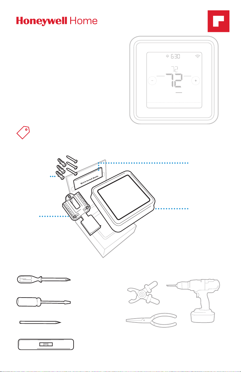
Included in your box
Screws and
anchors
UWP™
Mounting
System
(UWP)
Mode
Heat
Wake Away HomeSleep
Menu FanMode
Fan
Auto
Quick Install
Guide
RTH8500
Thermostat
Tools you will need Tools you may need
ewdriver
ewdriver
Wire stripper
Needle-nose pliers Drill and drill bit
Page 2
Quick Installation Guide
OFF
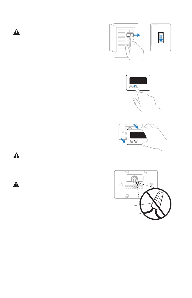
Removing your old thermostat
1 Turn power OFF.
To protect yourself and your
equipment, Turn off the power at the
breaker box or switch that controls
your heating/cooling system.
2 Check that your system is off.
Change the temperature on your
old thermostat. If you don’t hear the
system turn on within 5 minutes, the
power is off.
Note: If you have a digital
thermostat that has a blank display,
skip this step
3 Remove the old thermostat’s
faceplate.
On most thermostats, you can take
off the faceplate by grasping and
gently pulling. Some thermostats
may have screws, buttons, or clasps.
Do not remove any wires from your
thermostat at this time!
OFF
ON
OFF
Switch
Breaker box
75
4 Make sure there are no 120/240V
wires.
Do you have thick black wires with
wire nuts?
Is your thermostat 120V or higher?
If you answered yes to either of
these questions, you have a line
voltage system and the thermostat
will not work.
If you are unsure visit:
honeywellhome.com/support
Wire nut
Thick black wire
2
Page 3

RTH8500 Series
1/4” to 3/8”
5 Take a picture of how your wiring
looks right now.
Be sure to include the letters
next to the terminals where the
wires are inserted. This will be a
helpful reference when wiring your
thermostat.
Tip: If the color of your wires has
faded or if 2 terminals have the
same wire color, use the wire labels
provided in the package to label
each wire.
6 Record if you have wires in the following terminals.
Do not include jumpers as a part of your count. The thermostat does not
need jumpers.
Terminal Wire Color
R
R
h
Rc
7 Write down the color of the wires.
Check mark the wires that are connected to terminals. Next to the check mark,
write down the color of the wire. Do not include jumpers as a part of your
count.
Check all that apply (Not all will apply):
Terminal Wire Color
Y
Y2
G
C
Terminal Wire Color
A or L/A
O/B
W2 or AUX
E
W
K
The RTH8500 thermostat does not support S or U terminals.
If there are wires in terminals that are not listed, you will need additional
wiring support. Visit honeywellhome.com/support to find out if the thermostat
will work for you.
3
Page 4
Quick Installation Guide
8 Disconnect the wires and remove the old wall plate.
Use a screwdriver to release wires from terminals. Then, use a wire label to
identify each wire as it’s disconnected. The letter on the wire label should match
the letter on the terminal.
Tip: To prevent wires from falling back into the wall, wrap the wires around a
pencil.
Wiring Labels
Apply these wiring labels to
each wire with the appropriate
terminal designation as you
remove it from the existing
thermostat.
690823EFS03 • Rev. 0516 • Printed in U.S.A.
Installing your RTH8500 thermostat
RTH8500
Thermostat
Screws
UWP
Mounting
System
Anchors Wall
Étiquettes de fils
Lorsque vous retirez les fils
des bornes du thermostat
existant, collez ces étiquettes
sur chaque fil correspondant
B
G
R
V/VR
X
AUX
à la lettre de la borne.
B
Y2
Y2
G
H
H
R
RC
RC
V/VR
W
W
X
X1
X1
AUX
Rótulos para los cables
Coloque estos rótulos, con la
designación de las terminales, en cada cable al remover
los cables del termostato
actual.
C
C
E
E
F
F
L
L
O
O
P
P
RH
RH
T
T
U
U
W1
W1
W2
W2
W3
W3
X2
X2
Y
Y
Y1
Y1
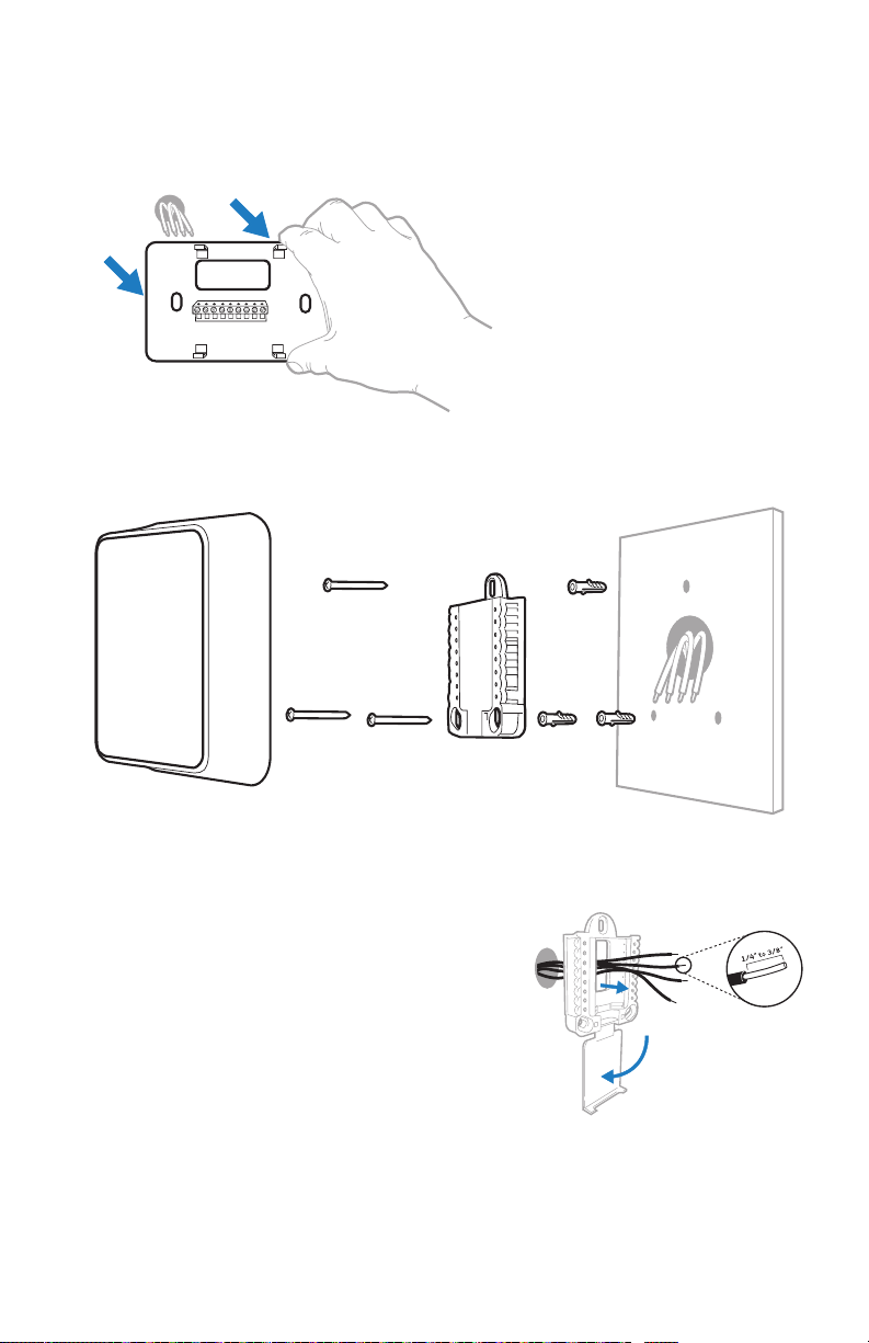
9 Bundle and insert wires through the UWP.
Pull open the UWP and insert the bundle of
wires through the back of the UWP.
Make sure at least 1/4-inch of each wire
is exposed for easy insertion into the wire
terminals.
4
Page 5
RTH8500 Series
10 Insert the wall anchors.
It is recommended that you use the
wall anchors included in the box to
mount your thermostat.
You can use the UWP to mark where
you want to place the wall anchors.
a) Level the wall plate.
b) Mark the location of the wall
anchors using a pencil.
c) Drill the holes.
d) Insert wall anchors.
e) Make sure anchors are flush with
wall.
Tip: If your box contains red anchors,
drill 7/32” holes.
If your box contains yellow anchors,
drill 3/16” holes.
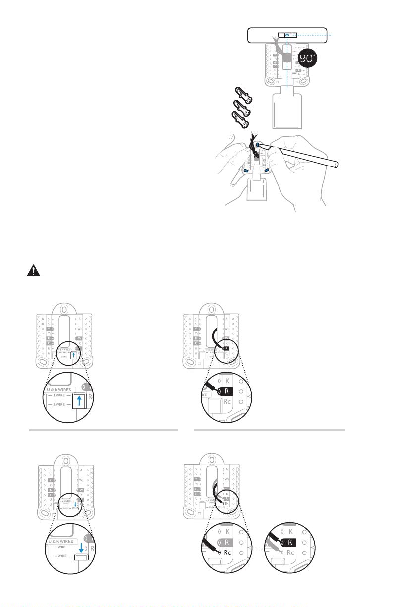
11 Set R-switch position and insert R-wire or wires.
Set the R-switch up or down based on your wiring notes in Step 7.
Insert wires into the inner holes of the terminals on the UWP. The tabs will
stay down once the wire is inserted.
If you have 1 R-wire (R,Rh, or Rc)
1. Set R-switch
to the up
position.
or
If you have 2 R-wires (R or Rh, and Rc)
1. Set R-switch
to the down
position.
5
2. Insert your
R-wire (R, Rh
or Rc) into
R-terminal.
2. Insert your Rc wire
into Rc-terminal
3. Insert your R
or Rh wire into
RTerminal.
Page 6
Quick Installation Guide
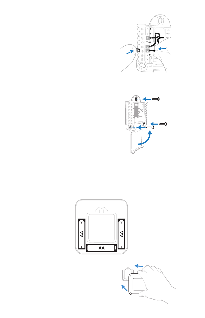
12 Connect wires from Step 7.
Depress the tabs to put the wires into
the inner holes of their corresponding
terminals on the UWP (one wire per
terminal) until it is firmly in place.
Gently tug on the wires to verify
they are secure.
Tip: If you need to release the wires
again, push down the terminal tabs
on the sides of the UWP.
13 Mount the UWP and close the door.
Mount the UWP using the provided
screws. Install all three screws into
the wall anchors for a secure fit on
your wall. Close the door after you’re
finished.
14 Confirm wiring matches snapshot.
Please confirm wiring matches
terminals from the photo you took in
Step 5.
This wiring is just an example,
yours may vary.
Use 3x supplied
screws (#8 11/2
for red anchors
and #6 11/2 for
yellow anchors)
15 Install batteries.
Insert three AA alkaline batteries in the back of the thermostat as shown.
NOTE: The RTH8500 thermostat works in battery mode or normal power
mode if a C-wire is available.
16 Attach your thermostat.
Align the thermostat onto the UWP
and firmly snap it into place.
6
Page 7
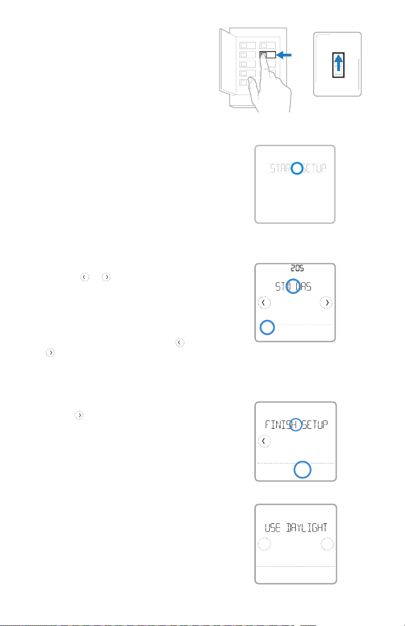
17 Turn your power ON.
ON
Turn on the power at the breaker box
or switch that controls the heating/
cooling system.
18 Return to the thermostat
Return to the thermostat. Confirm
the screen shows START SETUP.
If your thermostat does not show
START SETUP, please contact
Honeywell Home support.
19 Start setup.
Touch START SETUP to begin
20 Navigate and edit setup options.
Use the or to navigate
through all the setup options. To
see a list of all setup options, go to
pages 910.
To edit an option, touch Edit or touch
text area.
The value is now blinking. Use
to select the correct value.
Touch Done or touch text area once
the correct value is selected
or
Breaker box
Done
ON
Cancel
RTH8500 Series
ON
OFF
Switch
21 Finish setup.
Touch
SETUP. Touch Select or touch text
area.
until you see FINISH
22 Set time and date.
Set daylight saving time if you are in
an area that follows daylight saving
time. Set date, clock format, and
time on the next screens.
23 Your thermostat is now setup.
Refer to page 8 for more
information about basic operation.
Select
No
Back
7
Yes
Page 8

Quick Installation Guide
Key features
Desired
temperature
Displays desired
indoor temperature.
Mode
Select system
mode Auto/Heat/
Cool/Off/EM Heat
(emergency heat).
System status
information
Cool On, Heat On
Emergency Heat On,
Recovery, or Auto
Changeover On.
NOTE: Heat On/
Cool On may flash
for 5 minutes for
compressor delay.
Heat On
Following Schedule
Mode
Heat
Wake AwayHomeSleep
Menu
Contains features:
schedule, screen
lock, clean
screen, and other
thermostat settings.
NOTE: Long press
of Menu button
for 5 seconds to
access Advanced
Menu options.
Indoor
Temperature
Displays current
indoor temperature.
AM
Recovery
Auto Chg. On
Fan
Auto
Menu FanMode
Fan
Select Fan mode
Auto/On/Circulate.
Adjust
temperature
Touch + or - to set
your desired indoor
temperature.
Schedule period
Shows schedule
period: Wake/
Away/Home/
Sleep.
8
Page 9

RTH8500 Series
System Setup options
To access all system options in the table below, press and hold MENU for 5 seconds.
Tou ch
or
to scroll through the list.
Number Description Optio ns (factor y default in b old)
0 = NonProgrammable
1 = 1Week Prog rammable
2 = 5-2 Progra mmable
120 Scheduling Options
125
200 Heati ng System Type
205
218 Reversing Valve O/B
220
221
230 Fan Control
300 System Changeover
303 Auto Differential
Temperature Indication
Scale
Heating Equipment
Type
Cool St ages /
Compressor Stages
200= Conv / 200 =HP
Heat St ages / Back up
Heat Stages Heat
Stages
3 = 511 P rog ra mma bl e
4 = 7Day Progr ammable
Note: You can c hange defaul t MOFR, SAS U schedule he re. To edit perio ds during days ,
temper ature setpo ints, or to turn S chedule On /Off, touch MEN U and go to SCHEDU LE.
0 = Fahrenheit
1 = Cel sius
1 = Conve ntional Forc ed Air Heat
2 = Heat Pu mp
3 = Radian t Heat (Boile r)
5 = None (Co ol Only)
Note: This option selects the basic system type your thermostat will control.
Conventional Forced Air Heat:
1 = Standa rd Efficie ncy Gas For ced Air
2 = High Ef ficiency G as Forced Ai r
3 = Oil For ced Air
4 = Elec tric Force d Air
5 = Hot Wate r Fan Coil
Heat Pum p:
7 = Air to Ai r Heat Pump
8 = Geot hermal
Radiant Heat:
9 = Hot Wate r Radiant Hea t
12 = Steam
Note: Thi s option sele cts the equip ment type yo ur thermost at will control . Note: This fea ture is
NOT disp layed if featur e 200 is set to Cool Onl y.
0 = O (O/B in C ool)
1 = B (O/B in He at)
Note: This option is only displayed if the Heat Pump configured. Select whether reversing valve
O/B shou ld energize in co ol or in heat.
0, 1, 2
Note: Select how many Cool or Compressor stages of your equipment the thermostat will
control. Maximum of 2 Cool/Compressor Stages. Set value to 0 if you do not have Cool Stage/
Compressor Stage.
Heat St ages: 1, 2
Backu p Heat Stage s: 0, 1
Note: Se lect how many He at or Aux/E s tages of your eq uipment the th ermostat wi ll control.
Maximu m of 2 Heat Stages f or conventio nal systems . Maximum of 1 Au x/E stage fo r systems
with mor e than 1 heating e quipment ty pe. Set valu e to 0 if you do not have He at Stage/Ba ckup
Heat Stage.
1 = Equipment
2 = Thermostat
Note: Thi s ISU is only dis played if ISU 205 is s et to Electri c Forced Air or Fa n Coil.
0 = Manual
1 = Automatic
Note: Thermostat can automatically control both heating and cooling to maintain the desired
indoor t emperature . To be able to selec t “automatic” sy stem mode on the rmostat hom e screen,
turn thi s feature ON. Turn O FF if you want to con trol heating o r cooling manu ally.
0 °F to 5 °F o r 0.0 °C to 2.5 °C
Note: Dif ferential i s the minimum nu mber of degree s rise or fall re quired duri ng off cycle to
switch from the last active mode (heat or cool) to the opposite mode when the thermostat is
in auto-changeover. Differential is NOT deadband. The deadband temperature between when
heating (or cooling) cycles on and cycles off to maintain setpoint is not adjustable. Honeywell
Home us es an algorith m that fixes de adband at 0 °F.
9
Page 10

Quick Installation Guide
Number Description Optio ns (factor y default in b old)
1 - 6 CPH (3 CP H)
365
366
370
371
375
425 Smart Respons e
430
431
702 Air Filte rs
711
1401 Idle Brightness
1410 Clock Format 12 hour, 24 hour
1415 Daylight saving time
Cool 1 C PH (Cooling
cycl e rate stage 1)
Cool 2 C PH (Cooling
cycl e rate stage 2)
Heat 1 CP H (Heating
cycl e rate stage 1)
Heat 2 CP H (Heating
cycl e rate stage 2)
Aux He at CPH (Heati ng
cycl e rate Auxili ary
Heat)
Minimum Cool
Temperature Setpoint
Maximum Heat
Temperature Setpoint
Air Fil ter 1
Replacement Reminder
Note: This ISU is only displayed when Cool /Compressor Stages is set to 1 or more stages. Cycle
rate lim its the maximu m number of time s the system c an cycle in a 1 hour p eriod measu red
at a 50% load. F or example, w hen set to 3 CPH, at a 50% l oad, the most t he system will c ycle
is 3 time s per hour (10 minutes o n, 10 minutes off ). The system c ycles less o ften when loa d
condit ions are less t han or greater th an a 50% load.
1 - 6 CPH (3 CP H)
Note: This ISU is only displayed when Cool /Compressor Stages is set to 2.
1 - 12 CPH
Note: This ISU is only displayed when Heat Stages is set to 1 stage or more stages. Cycle rate
limits t he maximum num ber of times th e system can cy cle in a 1 hour per iod measured a t a
50% load. F or example, wh en set to 3 CPH, at a 50% lo ad, the most th e system will c ycle is
3 times p er hour (10 minutes on , 10 minu tes off). Th e system cycl es less oft en when load
condit ions are less t han or greater th an a 50% load. The re commended (de fault) cycl e rate
settings are below for each heating equipment type:
Standa rd Efficie ncy Gas Forced A ir = 5 CPH; High Ef ficiency Ga s Forced Air = 3 CP H; Oil
Forced A ir = 5 CPH; Electr ic Forced Air = 9 C PH; Fan Coil = 3 CPH ; Hot Water Radian t Heat
= 3 CPH; Ste am = 1 CPH.
1 - 12 CPH
Note: This ISU is only displayed when Heat Stages is set to 2 stages. The recommended
(default ) cycle rate set tings are be low for each hea ting equipme nt type:
Standa rd Efficie ncy Gas Forced A ir = 5 CPH; High Ef ficiency Ga s Forced Air = 3 CP H; Oil
Forced A ir = 5 CPH; Electr ic Forced Air = 9 C PH; Fan Coil = 3 CPH ; Hot Water Radian t Heat
= 3 CPH; Ste am = 1 CPH.
1 - 12 CPH
Note: Thi s ISU is only dis played when I SU 200 = Heat Pump and I SU 221=1. It is only d isplayed
when Auxiliary Heat is configured. The recommended cycle rate settings are below for each
heating equipment type:
Standa rd Efficie ncy Gas Forced A ir = 5 CPH; High Ef ficiency Ga s Forced Air = 3 CP H; Oil
Forced A ir = 5 CPH; Electr ic Forced Air = 9 C PH.
0 = No
1 = Yes
Note: Smart Response is a comfort setting. Heat or Cooling equipment will turn on earlier,
ensuring the indoor temperature will match the setpoint at the scheduled time. See page 16.
50 °F to 99 ° F (50 °F)
10.0 °C to 37.0 °C (10.0 °C)
Note: Th e cool temper ature cannot be s et below this l evel.
40 °F to 90 ° F (90 °F)
4.5 °C to 32 .0 °C (32.0 °C)
Note: Th e heat tempera ture cannot be s et above this le vel.
0 - 1
Note: Thi s ISU refers to t he number of air f ilters in the s ystem.
0 = Off
1 = 10 Run Time D ays
2 = 20 Run Tim e Days
3 = 30 Run Ti me Days
4 = 45 Run Tim e Days
5 = 60 Run Ti me Days
6 = 90 Run Ti me Days
7 = 120 Run Tim e Days
8 = 150 Run Tim e Days
9 = 30 Cale ndar Days
Note: Se t a reminder for w hen to change you r air filter. Choo se either ca lendar or equi pment run
time-based reminder.
0= Of f, 0 - 5
Note: Ad just brightn ess of an inact ive backligh t (idle screen) f rom default 0 (ba cklight of f) to 5
(maximum brightness). Common wire required for settings 15.
0 = Off
1 = On
Note: Se t to Off in areas t hat do not follow D aylight Savi ng Time.
10 = 45 Calen dar Days
11 = 60 Cal endar Days
12 = 75 Calen dar Days
13 = 3 Calen dar Months
14 = 4 Calenda r Months
15 = 5 Calen dar Months
16 = 6 Calen dar Months
17 = 9 Calenda r Months
18 = 12 Calen dar Months
19 = 15 Calen dar Months
NOTE: Once you have cycled through all of the System Setup numbers, Done is displayed. Press Select to
save and exit.
10
Page 11
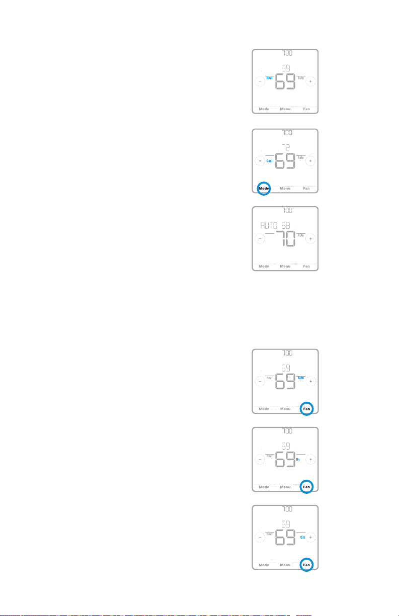
System operation settings
AM
1 Press the Mode button to cycle to the
next available System mode.
2 Cycle through the modes until the
required System mode is displayed
and leave it to activate.
NOTE: Available System modes vary by
model and system settings.
System modes:
‒ Auto: Thermostat selects heating
or cooling as needed.
‒ Heat: Thermostat controls only the
heating system.
‒ Cool: Thermostat controls only the
cooling system.
‒ Em Heat (only for heat pumps
with auxiliary heat): Thermostat
controls Auxiliary Heat. Compressor
is not used.
‒ Off: Heating and cooling system is
off. Fan will still operate if fan is set
to On or Circulate.
Following Schedule
Following Schedule
Mode
Following Schedule
Mode
RTH8500 Series
AM
Mode
Fan
AwayHome
AM
Fan
AwayHome
Auto Chg. On
Fan
AwayHome
Fan operation settings
1 Press the Fan button to cycle to the
next available Fan mode.
2 Cycle through the modes until the
required Fan mode is displayed and
leave it to activate.
NOTE: Available Fan modes vary with
system settings.
Fan modes:
‒ Auto: Fan runs only when the
heating or cooling system is on.
‒ On: Fan is always on.
‒ Circ: Fan circulates randomly
about 33% of the time.
11
Following Schedule
Mode
Following Schedule
Mode
Following Schedule
Mode
AM
Fan
AwayHome
AM
Fan
AwayHome
AM
Fan
AwayHome
Page 12
Quick Installation Guide
Heat Cool
(10:00
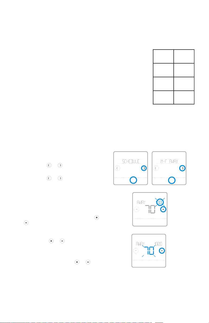
Program Schedule
You can program four time periods each day, with different settings for weekdays
and weekends. We recommend the pre-set settings (shown in the table below),
since they can reduce your heating/cooling expenses.
Wake - Set to the time you wake up and the
temperature you want during the morning, until you
leave for the day.
Away - Set to the time you leave home and the
temperature you want while you are away (usually an
energy-saving level).
Home - Set to the time you return home and the
temperature you want during the evening, until
bedtime.
Sleep - Set to the time you go to bed and the
temperature you want overnight (usually an energysaving level).
NOTE: To temporarily or permanently override any of the above program
schedules, see page 13.
Wake
(6:00 am)
(8:00 am)
Home
(6:00 pm)
Sleep
70 °78
Away
62 °85
70 °78
62 °82
pm)
The above table is only an example.
°
°
To adjust program schedules
1 Touch Menu on the thermostat home
screen.
2 Touch the or arrows until you
see SCHEDULE, then touch Select.
3 Touch the or arrows to select a
period in a day or set of days, then
touch Select on the period you want
to edit. (You can only edit a period of
days according to the schedule type
selected. To change schedule type,
see setup # 120 on page 9.)
4 Touch the time area, then touch or
to adjust when the period starts.
Touch Select to confirm.
5 Touch the temperature area,
then touch
preferred temperature for the
mode that’s currently active (either
heating or cooling). Touch Select
to confirm. Then touch
adjust your preferred temperature
for the inactive mode. Touch Select to
confirm.
or to adjust your
or to
Back Select Back Select
HeatTo
Back Select
AM
HeatTo
Back Select
Sched.
On/Off
AM
°
°
12
Page 13
RTH8500 Series
AM
Heat On
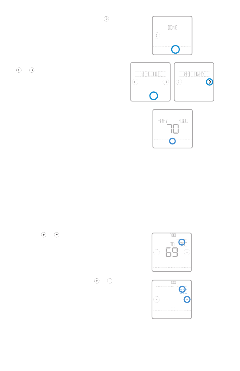
6 Edit the next period or use the
until you see Done, then press Select
to save changes and go to the home
screen.
NOTE: To temporarily cancel a schedule
period (such as SaturdaySunday Away,
Back Select
Sched.
On/O
for example, because you’ll be home), go
to the SCHEDULE option and touch the
or arrows to select a period. Touch
Select on the period you want to cancel,
then touch Cancel Period. To reactive the
period you cancelled, touch Cancel Period
again to select period start time and
Back Select
Back Select
Sched.
On/O
preferred temperature.
AM
HeatTo
Cancel Period
Done
Schedule overrides
Hold Until (temporary hold): Overrides the current temperature setpoint for a
maximum of 12 hours. You might use this feature to hold a temperature until a
specific time.
Permanent hold: Overrides the current temperature set point permanently until
you manually change it or reactivate a schedule.
Program schedule override (temporary)
1 Touch or on the thermostat
home screen to set your desired
temperature. Hold Until will appear
together with the time the hold will
end.
2 To change when the hold will end,
touch the time and wait until the time
starts blinking. Then, touch
to set when you want the hold to end.
Touch Hold Until once more to confirm
changes and return to the home
screen.
NOTE: After the hold period ends, the
thermostat will automatically return to
the program schedule. If you want to
cancel the hold, touch Hold Until and then
touch Run Schedule.
or
13
Hold Until
Mode
Heat
Menu FanMode
Run Schedule
Back
AM
Fan
Auto
AM
Hold UntilPermanent Hold
AM
Page 14

Quick Installation Guide
Program schedule override (permanent)
1 Touch or on the thermostat
home screen to reach your desired
temperature. Hold Until will appear
together with the time you want the
AM
Heat On
Hold Until
Mode
Heat
AM
Fan
Auto
hold to end.
2 Touch Hold Until. Permanent Hold will
appear on screen. Touch Permanent
Hold to hold this temperature until you
manually change it.
NOTE: To end permanent hold and
Menu FanMode
AM
Hold UntilPermanent Hold
AM
return to the program schedule, touch
Permanent Hold and then touch Run Schedule.
Run Schedule
Back
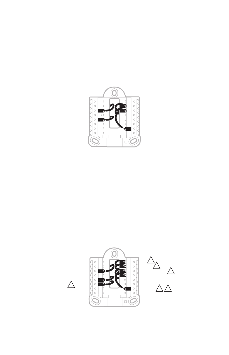
Wiring—conventional systems
Alternate wiring (conventional systems)
If labels do not match terminals, connect wires as shown below (see notes, below).
NOTES:
1. If you must connect both R and Rc wires, set the R Slider Tab to the down
position (2 wires).
2. If your old thermostat had both R and RH wires, set the R Slider Tab to the
down position (2 wires). Then connect the R wire to the Rc terminal, and the
RH wire to the R terminal.
3. If your old thermostat had only 1 C or C1 wire, connect it to the C terminal. If
your old thermostat had 2 C or C1 wires, wrap each separately with electrical
tape and do not connect them.
or Y1 or M
or C1 or X or B
3
or F
A
S
S
Y
Y
2
Y
G
C
U
U
L/A
O/B
AUX
2
W
E
W
K
R
Rc
or W1 or H
or R
or RH or 4 or V
2
2
14
Page 15
RTH8500 Series
Wiring—heat pump
Connect wires: heat pump
1 Match each labeled wire with same letter on new thermostat.
2 Insert the wires into the matching terminal.
NOTE: If you have difficulty inserting wires, you may have to press down the
terminal push button next to the corresponding terminal.
Labels don’t match?
If labels do not match the letters on the thermostat, see “Alternate wiring (for
heat pumps only)” below.
S
S
Y
Y
G
C
U
U
A
L/A
O/B
2
AUX
W
E
W
K
R
Rc
Alternate wiring (for heat pumps only)
NOTES:
1. Keep R Slider Tab in the up position (1 wire).
2. If your old thermostat had both V and VR wires, stop now and contact a
qualified contractor for help.
3. If your old thermostat had separate O and B wires, attach the B wire to the C
terminal. If another wire is attached to the C terminal, stop now and contact
a qualified contractor for help.
4. If your old thermostat had Y1, W1 and W2 wires, stop now and contact a
qualified contractor for help.
5. This model doesn’t suppor t the heat pump fault alert (L/A terminal). If this
is desired, please contact a contractor for replacement model.
5
or F
or H or B
3
or W or W1 or W2
or X or X2
or V or VR
4
21
or Y1 or M
or X or B
3
or F
S
S
Y
Y
2
G
C
U
U
A
L/A
O/B
2
W
AUX
E
W
K
R
Rc
NOTE: Do NOT use W for heat pump applications. Auxiliary heat must wire to
AUX or E.
15
Page 16

Quick Installation Guide
Smart Response® Technology
This feature allows the thermostat to “learn” how long the furnace and air
conditioner take to reach programmed temperature settings, so the temperature
is reached at the time you set. For example: Set the Wake time to 6 am, and the
temperature to 70°. The heat will come on before 6 am, so the temperature is 70°
by the time you wake at 6. The message “Recovery” is displayed when the system
is activated before a scheduled time period.
Battery replacement
Batteries are required to provide power when common wire is
not used. Batteries are recommended to provide backup power
if common wire is used. Install fresh batteries immediately when
the low battery icon appears. The icon appears about two months
before the batteries are depleted.
Even if the low battery icon does not appear, you should replace batteries once a
year, or before leaving home for more than a month.
If batteries are inser ted within two minutes, the time and day will not have to be
reset. All other settings are permanently stored in memory, and do not require
battery power.
NOTE: When replacing batteries, alkaline batteries are recommended.
Setting the time and date
Setting the time
1 Touch Menu on the thermostat home
screen.
2 Touch the or arrows until you
see CLOCK, then touch Select.
3 Touch the or arrows until you
see SET TIME, then touch Select.
4 Press or to set the time (or
press and hold the buttons to move
more quickly). Touch Done when
finished.
5 Set clock format (12 hours or 24
hours) and daylight saving time in
the same CLOCK sub-menu.
Back Select
PM
Done Cancel
16
Page 17
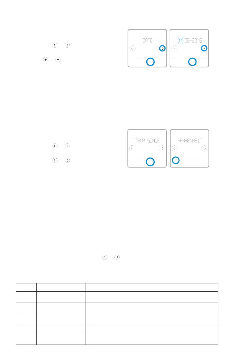
Setting the date
1 Touch Menu on the thermostat home
screen.
2 Touch the or arrows until you
see DATE, then touch Select.
3 Touch or to set the month, then
Back Select
touch Select to confirm.
4 Continue to set day and year in the
same way. Touch Select to save your
changes.
Choosing Fahrenheit or Celsius
To select a temperature scale, follow the
steps below.
1 Touch Menu on the thermostat home
screen.
2 Touch the or arrows until you
see TEMP SCALE, then touch Select.
3 Touch the or arrows to select
FAHRENHEIT or CELSIUS then
touch Done to save your changes.
4 Touch Back to return to the
thermostat home screen.
Back Select
RTH8500 Series
Back Select
Recovery
Done
Cancel
Alerts and maintenance reminders
1 Touch Menu on the thermostat home screen, then you’ll see the ALERTS sub-
menu. (The ALERTS sub-menu will only be available when there’s an active
alert.)
2 Touch Select to view the alert. A 3-digit alert code will appear by the
thermostat’s clock and a description of the alert will scroll on the screen.
3 If the alert is non-critical, you’ll have the option to Snooze or Dismiss it. If you
have multiple alerts, touch the
alerts and follow steps 1 and 2 above.
To see what each 3-digit alert code means and the action you should take, refer to
the chart below.
Number Alert/Reminder Definition
170 Internal Memory Error The memory of the thermostat has encountered an er ror. Please repl ace the
173 Thermostat Temperature
Sensor Error
181 Replac e Air Filter (1) Replace air f ilter (1). Reset the timer by touching the " dismiss" but ton on
405 Low Battery Aler t The bat teries are getting low. Replace them within t wo months.
407 Critical Low Batter y Th e batteries are almost depleted and should be replaced as s oon as
thermostat.
The sen sor of the thermostat has encountere d an error. Please replace the
thermostat.
thermostat screen after it is repla ced.
possible.
or arrows to page through the list of active
17
Page 18

Quick Installation Guide
Troubleshooting
If you have difficulty with your thermostat, please try the following suggestions.
Most problems can be corrected quickly and easily.
Display is blank Make sure fresh AA alkaline batteries are properly installed (see
Cannot change
system setting to Cool
Fan does not turn on
when heat is required
Heating system is
running in cool mode
Heating or cooling
system does not
respond
Heat On / Cool On
flashing on the screen
Heat pump issues cool
air in heat mode, or
warm air in cool mode
Aux heat runs in
cooling
Cool runs with a call
for heat
page 6).
If powered by common (C-wire), verify circuit breaker and furnace
switch are turned on.
Verify furnace door is securely closed.
Check System Setup Option 220 to make sure the options are set to
either 1 or 2 (see page 9).
Check System Setup Option 205 to make sure it is set to match your
heating equipment (see page 9).
Check System Setup Option 200 or 218 to make sure it is set to
match your heating and cooling equipment (see page 9).
Press System to set system to Heat. Make sure the temperature is
set higher than the Inside temperature.
Press System to set system to Cool. Make sure the temperature is set
lower than the Inside temperature.
Check circuit breaker and reset if necessary.
Make sure power switch at heating & cooling system is on.
Make sure furnace door is closed securely.
Wait 5 minutes for the system to respond.
Compressor protection feature is engaged. Wait 5 minutes for the
system to restart safely, without damage to the compressor.
Check System Setup Option 200 or 218 to make sure it is set to
match your heating and cooling equipment (see page 9).
For heat pump systems, verify there is not a wire attached to W on
UWP systems. See “Wiring—heat pump” on page 15.
For heat pump systems, verify there is not a wire attached to W on
UWP systems. See “Wiring—heat pump” on page 15.
18
Page 19

RTH8500 Series
1-year limited warranty
Resideo warrants this product, excluding battery, to be free from defects in
workmanship or materials, under normal use and service, for a period of one (1)
year from the date of first purchase by the original purchaser. If at any time during
the warranty period the product is determined to be defective due to workmanship
or materials, Resideo shall repair or replace it (at Resideo’s option).
If the product is defective,
(i) return it, with a bill of sale or other dated proof of purchase, to the place from
which you purchased it; or
(ii) call Resideo Customer Care at 18004681502. Customer Care will make the
determination whether the product should be returned to the following address:
Resideo Return Goods, 1985 Douglas Dr. N., Golden Valley, MN 55422, or whether
a replacement product can be sent to you.
This warranty does not cover removal or reinstallation costs. This warranty shall
not apply if it is shown by Resideo that the defect was caused by damage which
occurred while the product was in the possession of a consumer.
Resideo’s sole responsibility shall be to repair or replace the product within
the terms stated above. RESIDEO SHALL NOT BE LIABLE FOR ANY LOSS OR
DAMAGE OF ANY KIND, INCLUDING ANY INCIDENTAL OR CONSEQUENTIAL
DAMAGES RESULTING, DIRECTLY OR INDIRECTLY, FROM ANY BREACH OF ANY
WARRANTY, EXPRESS OR IMPLIED, OR ANY OTHER FAILURE OF THIS PRODUCT.
Some states do not allow the exclusion or limitation of incidental or consequential
damages, so this limitation may not apply to you.
THIS WARRANTY IS THE ONLY EXPRESS WARRANTY RESIDEO MAKES ON
THIS PRODUCT. THE DURATION OF ANY IMPLIED WARRANTIES, INCLUDING
THE WARRANTIES OF MERCHANTABILITY AND FITNESS FOR A PARTICULAR
PURPOSE, IS HEREBY LIMITED TO THE ONE YEAR DURATION OF THIS
WARRANTY. Some states do not allow limitations on how long an implied warranty
lasts, so the above limitation may not apply to you.
This warranty gives you specific legal rights, and you may have other rights which
vary from state to state. If you have any questions concerning this warranty,
please write Resideo Customer Care, 1985 Douglas Dr, Golden Valley, MN 55422
or call 18004681502.
19
Page 20

33-00406-09
CAUTION: ELECTRICAL HAZ ARD
Can cause electrical shock or equipment damage. Disconnect power before
beginning installation.
CAUTION: MERCURY NOTICE
If this product is replacing a control that contains mercury in a sealed
tube, do not place the old control in the trash. Contact your local waste
management authority for instructions regarding recycling and proper
disposal.
Electrical Ratings
Terminal Voltage
(50/60Hz)
Running
Current
W Heating 20-30 Vac 0.02-1.0 A
W2 (Aux) Heating 20-30 Vac 0.02-1.0 A
E Emergency Heat 20-30 Vac 0.02-0.5 A
Y Compressor Stage 1 20-30 Vac 0.02-1.0 A
Y2 Compressor Stage 2 20-30 Vac 0.02-1.0 A
G Fan 20-30 Vac 0.02-0.5 A
O/B Changeover 20-30 Vac 0.02-0.5 A
L/A Input 20-30 Vac 0.02-0.5 A
NOTE: Not for use with 250, 500, or 750 MV systems.
Customer assistance
For assistance with this product,
please visit
http://honeywellhome.com
Or call Customer Care
toll-free at 18004681502.
Pull to remove the
thermostat from the
UWP.
Resi deo Inc., 1 985 Dougla s Drive Nor th
Golden Valley, MN 55422
www.resideo.com
This product is manufactured by Resideo Technologies, Inc., Golden Valley, MN, 1-800-468-1502
©2019 Resideo Technologies, Inc. The Honeywell Home trademark is used under license from Honeywell International Inc. All rights reserved.
33-00406—09 M.S. Rev. 09-19
Printed in U.S.A..
 Loading...