

Page 1
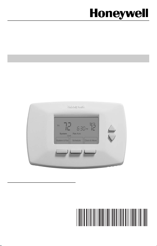
RTH7400D
Programmable Thermostat
OWNER’S GUIDE
The RTH7400D Thermostat provides electronic control of 24 Vac
heating and cooling systems or 750 mV heating systems.
For assistance with your Honeywell product, please visit
www.honeywell.com/yourhome
toll free at 1-800-468-1502.
or call Honeywell Customer Care
Read and Save these Instructions
Patents Pending
® U.S. Registered Trademark
© 2004 Honeywell International Inc.
All Rights Reserved
69-1726-1
Page 2

Contents
Prepare for Installation ............................................................ 3
Follow Important Instructions .................................................. 5
Remove Old Thermostat ......................................................... 6
Follow Special Instructions...................................................... 7
Label Old Thermostat Wires ................................................... 10
Mount New Wallplate to Wall .................................................. 11
Connect Wires to New Wallplate............................................. 15
Install Batteries........................................................................ 23
Attach New Thermostat to Wallplate ....................................... 24
Configure Installer Setup......................................................... 26
Customer Assistance .............................................................. 62
Limited One-Year Warranty..................................................... 63
69-1726—1 2
Page 3
Step 1. Prepare for Installation
e
.
Ó
e
/yourhome
G
R
G
R
C
C
O
UW3U
W3
8
on
ead and save
ese
s
t
é
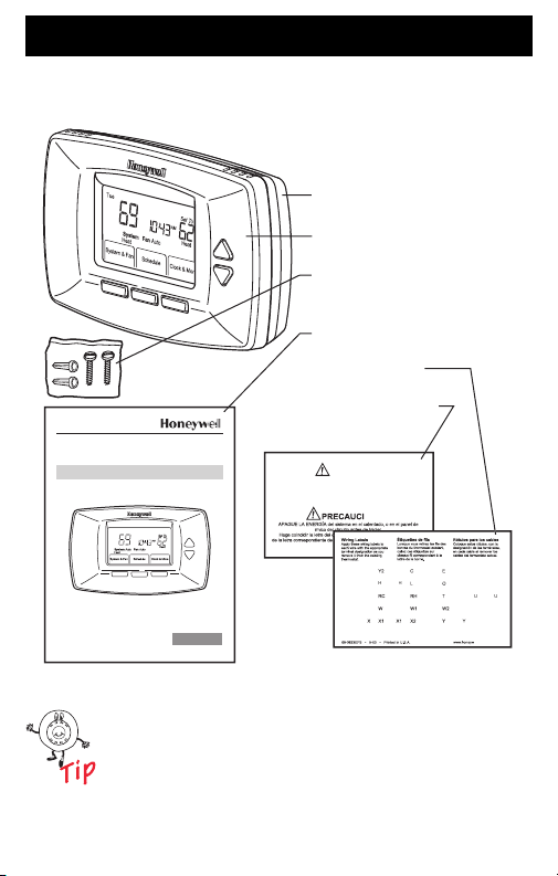
1. Check that the following items are included:
WALLPLATE
THERMOSTAT
MOUNTING SCREWS (2)
AND WALL ANCHORS (2)
OWNER'S GUIDE
WIRE LABELS
CAUTION CARD
OWNER'S GUIDE
M
R
th
instruction
CAUTION
TURN OFF POWER to system at the furnace, or at the fuse/circuit
breaker panel before you begin.
Match the letter of your old thermostat wire with the terminal of th
corresponding letter on your new thermostat or base
fusibles-interruptor
V/V
V/V
R
ll.com
M2227
If any of the items shown above are missing, call
Honeywell Customer Care at 1-800-468-1502
before returning the thermostat to the store.
3 69-1726—1
Page 4

Step 1. Prepare for Installation (Cont)
2. Check that you have everything required for the
installation:
• Two AA alkaline batteries
• No. 2 Phillips screwdriver and standard pocket
screwdriver
•Drill
• Drill bit—use 3/16 in. for drywall; use 7/32 in. for
plaster
• Level (optional)
• Hammer
•Pencil
• Electrical tape
69-1726—1 4
Page 5
Step 2. Follow Important Instructions
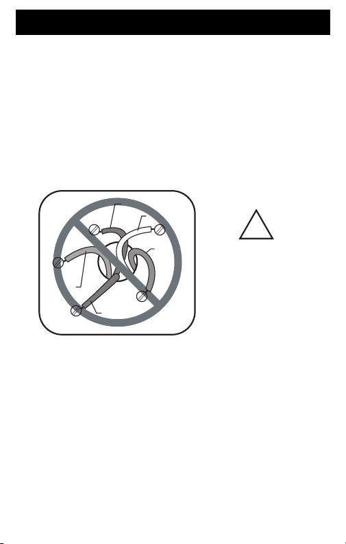
1. Do not connect the wires to the new thermostat
based on wire color because damage can occur to
the heating and/or cooling system.
These Installation Instructions explain later how to
use the enclosed wire labels to correctly mark the
wires connected to your old thermostat.
OLD THERMOSTAT
YELLOW
WHITE
R
RED
W
NEW THERMOSTAT
!
DO NOT WIRE
BASED ON
WIRE COLOR.
M22034
G
GREEN
RC
Y
ORANGE
5 69-1726—1
Page 6
Step 3. Remove Old Thermostat
1. Turn off power at the heating and/or cooling system
or fuse/circuit breaker panel.
2. Remove the cover from the old thermostat.
3. Remove the old thermostat from the wall or wall-
plate. Do not remove the wires.
OLD THERMOSTAT
WALLPLATE
Y
G
C
W
THERMOSTAT
R
.
1
8
.2
.9
.7
.5
L
O
N
R
.4
G
E
.25
.3
COVER
M22036
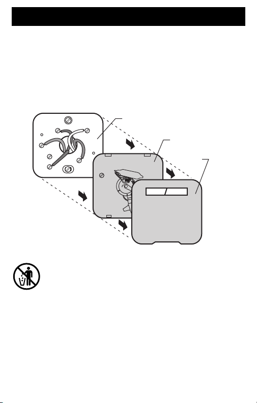
MERCURY NOTICE
If you are replacing a thermostat that contains mercury
in a sealed tube, do not place your old thermostat in the
trash.
Contact your local waste management authority for
instructions regarding recycling and the proper disposal
of an old thermostat containing mercury in a sealed
tube.
69-1726—1 6
Page 7
Step 4. Follow Special Instructions
1. If you have two C and/or C1 wires connected to
your old thermostat, do not connect them to your
new thermostat.
2. Disconnect the C and/or C1 wires. Make sure they
do not touch each other or any other wires.
3. Wrap the bare end of each C and/or C1 wire with
electrical tape.
OLD THERMOSTAT
Y
W
G
C
LETTER
DESIGNATION
SCREW
TERMINAL
WIRE
R
C
DO NOT CONNECT TO NEW
THERMOSTAT
7 69-1726—1
WIRE HOLE
M22201
Page 8
Step 4. Follow Special Instructions (Cont)
4. If you have only one C and/or C1 wire connected to
your old thermostat, connect this wire to C on the
new thermostat.
OLD THERMOSTAT
Y
G
R
C
CONNECT TO THE "C" ON THE
NEW THERMOSTAT
69-1726—1 8
W
LETTER
DESIGNATION
SCREW
TERMINAL
WIRE
WIRE HOLE
M22223
Page 9
Step 4. Follow Special Instructions (Cont)
5. If you find any wires not connected to your old
thermostat, do not connect them to your new
thermostat.
6. Wrap the end of the wires that are not connected
with electrical tape.
OLD THERMOSTAT
LETTER DESIGNATION
Y
G
C
R
W
SCREW TERMINAL
WIRE
R
WIRE HOLE
WIRES NOT CONNECTED –
DO NOT CONNECT TO
NEW THERMOSTAT
M22040
9 69-1726—1
Page 10
Step 5. Label Old Thermostat Wires
1. As you disconnect each wire, use the enclosed wire
labels to wrap a wire label around each wire that
matches the letter designation. Do not allow the
wires to fall into the wall opening after the wires are
disconnected.
2. Remove any remaining part of the old thermostat
from the wall.
OLD THERMOSTAT
Y
W
Y
G
G
RC
R
C
When connecting the wires to the new
thermostat, refer to the wire labels. Do not
connect wires to your new thermostat based on
the color of the wire.
69-1726—1 10
WIRE LABEL
W
R
LETTER
DESIGNATION
SCREW
TERMINAL
WIRE
R
WIRE HOLE
M22039
Page 11
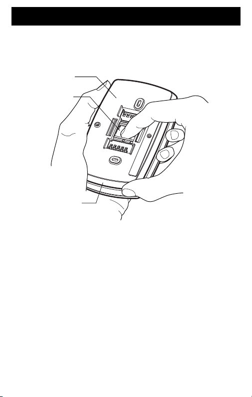
Step 6. Mount New Wallplate to Wall
1. Separate the wallplate from the thermostat as
shown.
WALLPLATE
WIRE HOLE
THERMOSTAT
M22267
11 69-1726—1
Page 12
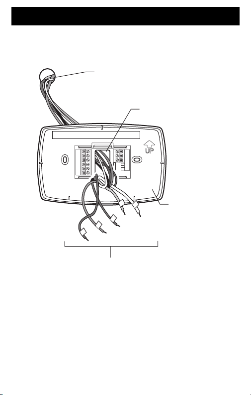
Step 6. Mount New Wallplate to Wall (Cont)
2. Pass the labeled wires through the wire hole on the
wallplate.
WALL OPENING
WIRE HOLE
PLATE
L
WAL
LABELED WIRES
69-1726—1 12
M22279
Page 13
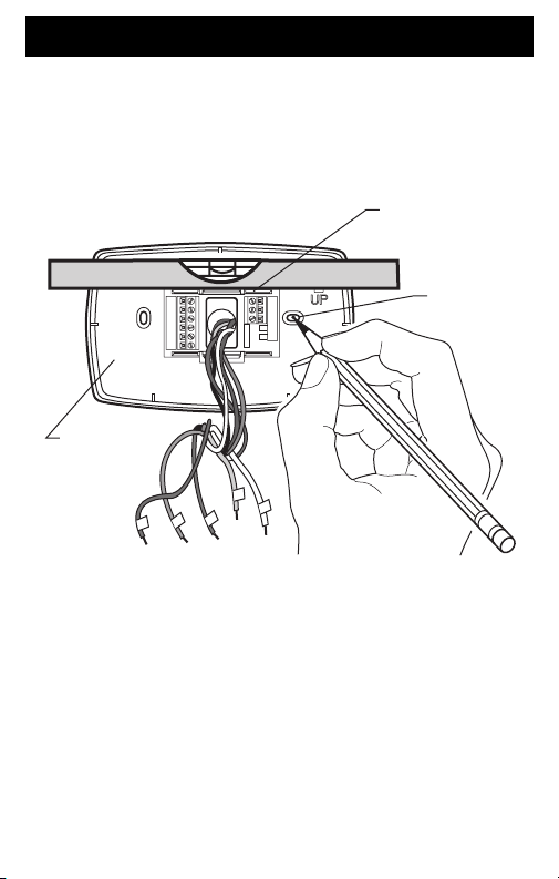
Step 6. Mount New Wallplate to Wall (Cont)
3. Position the wallplate on the wall with the arrow
pointing up. Level the wallplate (for appearance
only) and mark the two mounting holes with
a pencil.
PLACE LEVEL ON
LEVEL
WALLPLATE
M22292
SUPPORT TABS
MARK
MOUNTING
HOLES (2)
13 69-1726—1
Page 14
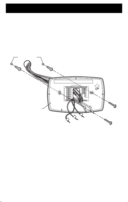
Step 6. Mount New Wallplate to Wall (Cont)
4. Move the wallplate aside and drill holes at the
locations marked on the wall. Drill 3/16 in. holes for
drywall or 7/32 in. holes for plaster.
5. Tap the wall anchors into the drilled holes until even
with the wall surface.
DRILLED
HOLES (2)
WALLPLATE
M22293
6. Position the wallplate over the wall anchors.
7. Insert the mounting screws into the wall anchors.
Check leveling, if desired, and tighten the mounting
screws.
WALL
ANCHORS (2)
MOUNTING
SCREWS (2)
69-1726—1 14
Page 15
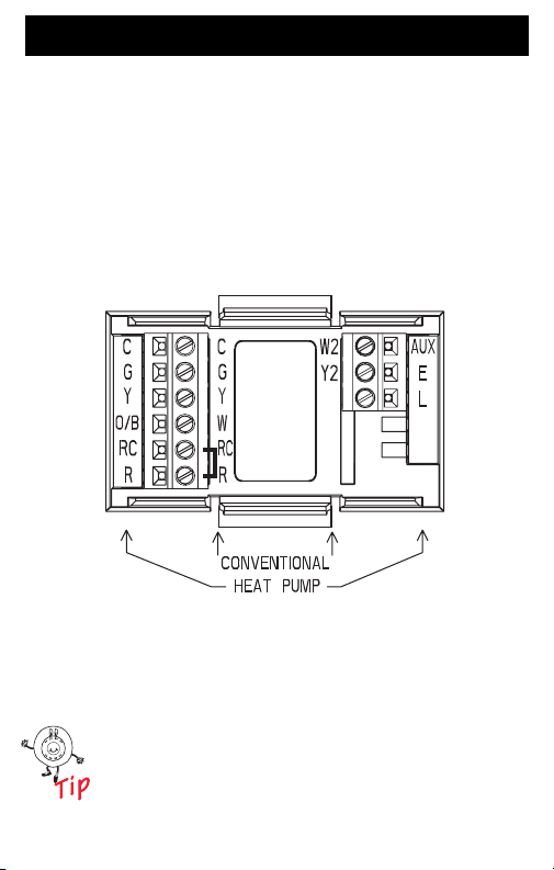
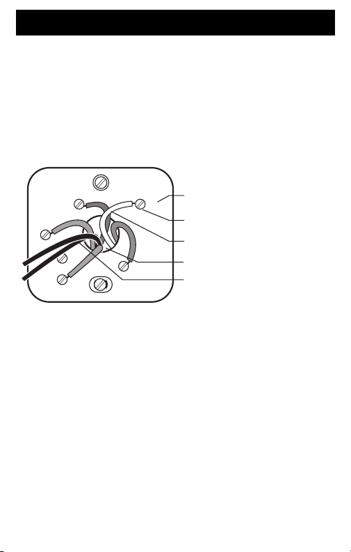
Step 7. Connect Wires to New Wallplate
1. Match the labeled wires to the letter designations
on the wallplate.
2. Select the correct letter designations to follow for
your system. If you have a standard heating and/or
cooling system, use the CONVENTIONAL letter
designations. If you have a heat pump system, use
the HEAT PUMP letter designations to wire the new
thermostat.
M22294
See table on page 30 to help you determine if
you have a CONVENTIONAL or HEAT PUMP
system.
15 69-1726—1
Page 16
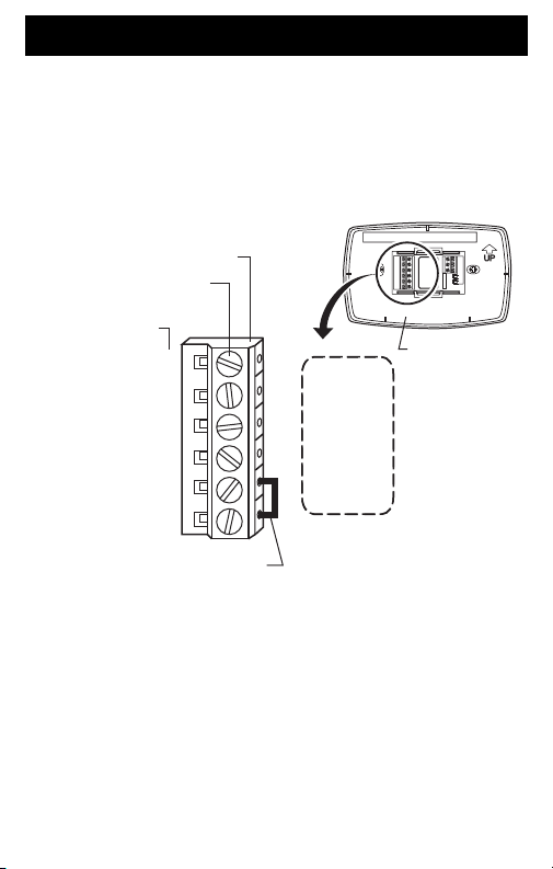
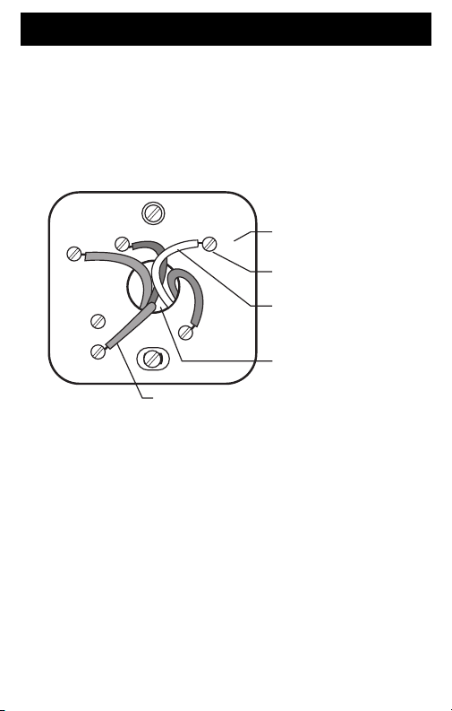
Step 7. Connect Wires to New Wallplate (Cont)
3. If wires are to be connected to both Rc and R,
loosen the Rc and R screw terminals and remove
the metal jumper wire.
4. If only one of the terminals, Rc or R, is to be
connected, leave the metal jumper wire in place.
TERMINAL BLOCK
SCREW TERMINALS
LETTER
DESIGNATIONS
C
G
Y
O/B
RC
R
WALLPLATE
METAL JUMPER WIRE
69-1726—1 16
M22295
Page 17
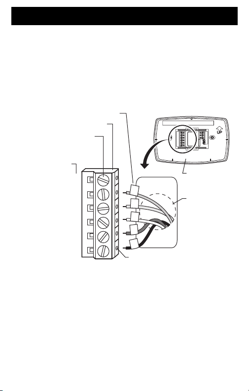
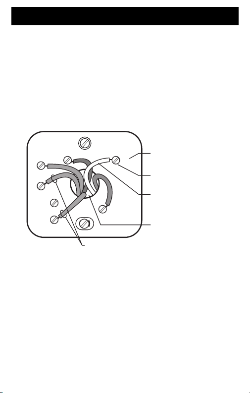
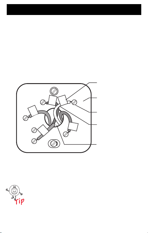
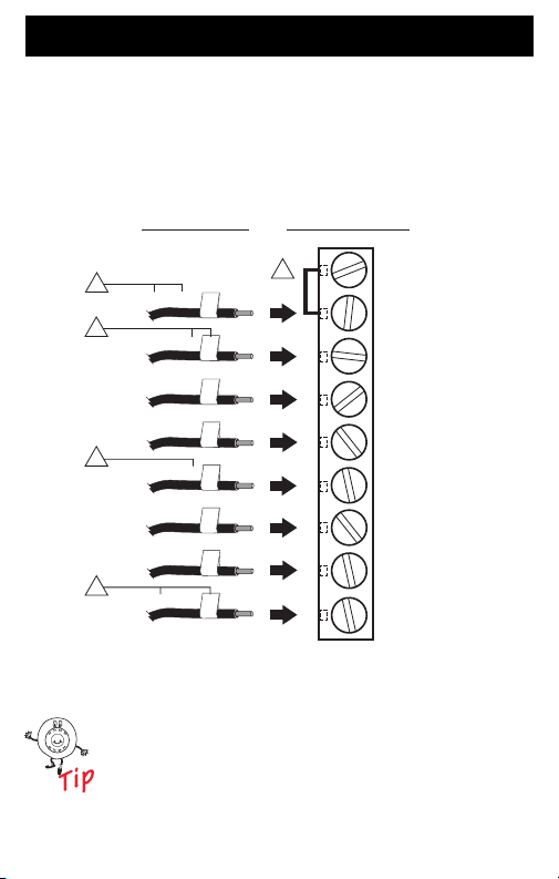
Step 7. Connect Wires to New Wallplate (Cont)
5. Loosen the screw terminals. Insert the labeled
wires into the holes on the side of the terminal block
that match the letter designations. Tighten the
screw terminals.
6. If any of the labeled wires do not match the letter
designations, see next page for wire connections.
LABELED WIRES
TERMINAL BLOCK
SCREW TERMINALS
CONVENTIONAL
LETTER
DESIGNATIONS
RC
C
G
Y
W
R
G
Y
W
C
R
R
INSERT WIRE IN HOLE
WALLPLATE
WIRE HOLE
M22325
17 69-1726—1
Page 18
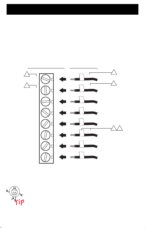
Step 7. Connect Wires to New Wallplate (Cont)
7. Compare letter designations on your old and new
thermostats. Use the information below if you are
wiring a CONVENTIONAL System. Use the
information on page 20 if you are wiring a Heat
Pump system.
CONVENTIONAL
letter designations
on the new thermostat
1
RC
1
R
W
Y
G
C
Y2
W2
Do not connect more than one wire to each
terminal. Be sure to read the notes referenced in
the numbered triangles above. These numbered
notes appear on the next page.
69-1726—1 18
Possible letter
designations on
the labeled wires
or R
RC
or RH, 4, V
R
or W1, H
W
or Y1, M
Y
or F
G
or C1, X, B
C
Y2
W2
2
2
3
M22208
4
Page 19

Step 7. Connect Wires to New Wallplate (Cont)
NOTES FOR CONVENTIONAL HEATING AND COOLING SYSTEMS
1
If wires will be connected to both RC and R on the new thermostat,
remove metal jumper wire between R
wire in place if only one of the terminals, R
on the new thermostat.
If wires were connected to both R and RH terminals on the old
2
thermostat, remove metal jumper wire between R
new thermostat. Connect the old R to the new R
to the new R.
3
If two C and/or C1 wires were connected to the old thermostat, do
not connect them to the new thermostat. Wrap the bare end of
each wire separately with electrical tape and do not use.
4
If one C and/or C1 wire was connected to the old thermostat, the
wire should be connected to the "C" letter designation on the new
thermostat.
C and R. Leave metal jumper
C or R, will be connected
C and R on the
C and the old RH
M22246
19 69-1726—1
Page 20
Step 7. Connect Wires to New Wallplate (Cont)
8. Compare letter designations on your old and new
thermostats. Use the information below if you are
wiring a HEAT PUMP system.
HEAT PUMP letter
designations on the
new thermostat
1
RC
R
O/B
Y
G
C
L
E
AUX
M22210
2
3
3
4
AUX, W1, W or
Possible letter
designations on
the labeled wires
VR or V or
R
H or B,
O
Y1 or M or
Y
F or
G
X or B,
C
F or
L
X2 or X,
E
W2
Be sure to read the note referenced in the
numbered triangles above. These numbered
notes appear on the next page.
69-1726—1 20
Page 21

Step 7. Connect Wires to New Wallplate (Cont)
NOTES FOR HEAT PUMP SYSTEMS
1
Leave metal jumper wire between RC and R in place.
2
If the old thermostat had separate wires on both the V and VR,
some system modification is required. Call your local heating
and cooling contractor for assistance.
If the old thermostat had wires on both O and B, be sure to
3
attach the B wire to the C letter designation on the new
thermostat. If another wire is already matched to the C, contact
Honeywell.
If the old thermostat had wires on W1, Y1 and W2, some
4
system modification is required. Call your local heating and
cooling contractor for assistance.
M22245
21 69-1726—1
Page 22

Step 7. Connect Wires to New Wallplate (Cont)
9. Push excess wire back into the wall opening. Keep
wires in the shaded area.
WIRE
WALL OPENING
SHADED AREA
WALLPLATE
M22297
69-1726—1 22
Page 23

Step 8. Install Batteries
1. Install two fresh AA alkaline batteries on the back of
the thermostat as marked on the thermostat.
BATTERIES (2)
BACK OF THERMOSTAT
BATTERY HOLDER
M22259
2. Remove tab labeled “Remove during installation”
in the lower right corner of the thermostat back.
REMOVE
TAB
INSTALLATION
REMOVE DURING
INSTALLATION
REMOVE DURING
M22298
23 69-1726—1
Page 24

Step 9. Attach New Thermostat to Wallplate
1. Align the screw blocks with the pins on the back of
the thermostat.
WALLPLATE
TERMINAL SCREW BLOCK
PINS ON
BACK OF
THERMOSTAT
M22299
2. Push the thermostat straight onto the wallplate until
it snaps into place.
3. Turn on the power at the heating and/or cooling
system or fuse/circuit breaker panel.
If the wires interfere with mounting the
thermostat to the wallplate, push the excess
wire back into the wall opening.
69-1726—1 24
Page 25

Step 10. Set the Calendar
eset
UseEdit
S
e
p
C
k
This thermostat is designed to automatically keep current
time and day in memory for up to ten years, under normal
use, once the calendar is set. When the thermostat is first
powered, the display is ready to set the calendar.
1. Use Up or Down arrow button to set the Month.
MONTH
YEAR
Tue
R
Fan
chedul
NextHoldSte
GO BACK BUTTON
GOES BACK TO LAST SETTING
DAY
loc
NEXT BUTTON
ADVANCE TO NEXT SETTING
UP AND DOWN
2. Press the Next button to advance to the Date.
3. Use the Up or Down arrow button to set the Date.
4. Press the Next button to advance to the Year.
5. Use the Up or Down arrow button to set the Year.
The calendar can be set anytime. See Step 11,
Configure Installer Setup, for instructions.
25 69-1726—1
BUTTONS
CHANGES
MONTH,
DAY AND
YEAR
DONE
BUTTON
ADVANCES
TO TIME
SETTING
SCREEN
M22302
Page 26

Step 10. Set the Calendar (Cont)
C
e
Done
6. Press the Done button to advance to the Time.
7. Use the Up or Down arrow button to set the Time.
UP AND DOWN BUTTONS
CHANGES TIME
lockMor
DONE BUTTON
ADVANCES TO HOME SCREEN
8. Press the Done button.
69-1726—1 26
M22303
Page 27

Step 11. Configure Installer Setup
m
&
an
S
e
C
k
&
e
o
ue
o
Cool
Se
o
1. Use the Installer Setup Menu to match your new
thermostat to your heating and/or cooling system.
Follow the steps in this section to set up your
thermostat.
2. Press and release the System button.
T
System Aut
HeatOff
Syste
Fan Aut
F
chedul
t T
loc
Mor
M22304
27 69-1726—1
Page 28

Step 11. Configure Installer Setup (Cont)
m
&
an
an
UseEdit
C
e
o
o
Cool
eset
Go
ack
p
C
e
3. Press and hold the center button for approximately
five seconds, until the screen changes.
System Aut
Fan Aut
Heat Off
Syste
4. Release the center button when the display on
your thermostat matches the display below.
F
F
ancelDon
M22305
R
69-1726—1 28
B
NextHoldSte
ancelDon
M22326
Page 29

11. Configure Installer Setup (Cont)
C
e
Done
od
Wake Leave
5. Press the Up or Down arrows to select your setting
for Installer Setup Number 0120 below.
6. After you select your setting, press the Next button
to go to the next Installer Setup Number.
7. Follow steps 5 and 6 to set Installer Setup Numbers
0130, 0140 and 0150 to complete setting the
calendar.
INSTALLER
SETUP NUMBER
Go Back
GOES BACK
TO LAST
INSTALLER
SETUP
Installer
Setup
Number
Installer
Setup
Name
0120 Date (Year
Upper)
0130
Date (Year
Lower)
0140
Date
(Month)
0150
Date
(Day)
Peri
Next
ADVANCE TO
NEXT INSTALLER
SETUP
lockMor
PRESS TO EXIT
INSTALLER SETUP
(Select Your Setting)
Settings
Select first two digits of current
calendar year (20 for year 2005, etc).
Select last two digits of current
calendar year (05 for year 2005, etc).
Select number that represents current
calendar month.
Select number that represents current
calendar date.
29 69-1726—1
FACTORY
SETTING
CHANGE
THE
FACT ORY
SETTING
M22307
Page 30

Step 11. Configure Installer Setup (Cont)
S
UP
C
k
More
Done
8. Press the Up or Down arrows to select your setting
for Installer Setup Number 0170.
9. After you select your setting, press the Next button
to go to the next Installer Setup Number.
INSTALLER
SETUP NUMBER
GOES BACK TO
LAST INSTALLER
SETUP
ADVANCE
TO NEXT
INSTALLER SETUP
Installer
Number
Installer
Setup
Setup
Name
0170 System
Type
Selection
1 - Heating and Cooling (Conventional) -- Gas, oil or
electric heating with central air conditioning.
2 - Single-stage Heat Pump with no back-up or
auxiliary heat -- the compressor runs in both
heating and cooling.
3 - Heat Only with no fan (Conventional) -- Gas, oil
or electric heating without central air conditioning.
No wire on the G terminal on new thermostat.
4 - Heat Only with fan (Conventional) -- Gas, oil or
electric heating without central air conditioning.
Typically wires are R, W and G on new thermostat.
5 - Hot Water Heat Only (Conventional) -- Gas or Oil
hot water heat with three wires connected to new
thermostat or for normally closed hot water values
with wires connected to R and Y on new thermostat.
6 - Cool Only (Conventional) -- Central air
conditioning only.
7 - Multistage Heat Pumps -- heat pump with auxiliary
or back-up heat.
8 - Multistage Conventional Heating and Cooling --
2 stages of Heat (wires on W and W2) and 2 stages
of Cool (wires on Y and Y2).
9 - Multistage Conventional Heating and Cooling - 2 stages of heat (wires on W and W2) and 1 stage
of Cool (wire on Y).
10 - Multistage Conventional Heating and Cooling - 1 stage of heat (wire on W) and 2 stages of Cool
(wires on Y and Y2).
69-1726—1 30
Go Back
Next
Set To
%
loc
IN
(Select Your Setting)
Settings
PRESS TO EXIT
TALLER SET
SETTING
ARROW
DOWN
ARROW
M22308
UP
Page 31

Step 11. Configure Installer Setup (Cont)
Clock
More
Done
od
Wake Leave
10. If you do not have a number 0180 on the left side of
your display, go to the next page.
11. If you have a number 0180 on the left side of your
display, press the Up or Down arrow to select your
setting for Installer Setup Number 0180.
12. After you select your setting, press the Next button
to go to the next Installer Setup Number.
INSTALLER
SETUP NUMBER
Go Back
GOES BACK
TO LAST
INSTALLER
SETUP
Installer
Setup
Number
Installer
Setup
Name
0180 Fan Control
in Heating
Peri
Next
Settings
PRESS TO EXIT
INSTALLER SETUP
ADVANCE TO
NEXT INSTALLER
SETUP
(Select Your Setting)
0 - Gas or Oil Heat -- Heating system
controls fan in a call for heat.
1 - Electric Heat -- Thermostat controls
fan in a call for heat.
31 69-1726—1
SETTING
UP
ARROW
DOWN
ARROW
M22309
Page 32

Step 11. Configure Installer Setup (Cont)
Clock
More
Done
od
Wake Leave
13. If you do not have a number 0190 on the left side of
your display, go to the next page.
14. If you have a number 0190 on the left side of your
display, press the Up or Down arrow to select your
setting for Installer Setup Number 0190.
15. After you select your setting, press the Next button
to go to the next Installer Setup Number.
INSTALLER
SETUP NUMBER
Go Back
GOES BACK
TO LAST
INSTALLER
SETUP
Installer
Setup
Number
ADVANCE TO
NEXT INSTALLER
SETUP
Installer
Setup
Name
0190 Heat Pump
Changeover
Valve
69-1726—1 32
Peri
Next
PRESS TO EXIT
INSTALLER SETUP
(Select Your Setting)
Settings
0 - Changeover Valve in Cooling --
Use this setting if you connected a
wire labeled O to the O/B terminal.
1 - Changeover Valve in Heating - Use this setting if you connected a
wire labeled B to the O/B terminal.
SETTING
UP
ARROW
DOWN
ARROW
M22310
Page 33

Step 11. Configure Installer Setup (Cont)
Clock
More
Done
od
e
16. If you do not have a number 0240 on the left side of
your display, go to the next page.
17. If you have a number 0240 on the left side of your
display, press the Up or Down arrow to select your
setting for Installer Setup Number 0240.
18. After you select your setting, press the Next button
to go to the next Installer Setup Number.
INSTALLER
SETUP NUMBER
GOES BACK
TO LAST
INSTALLER
SETUP
Installer
Setup
Number
0240 Heating
Next
Go Back
ADVANCE TO
NEXT INSTALLER
SETUP
Installer
Setup
Name
Cycle
Rate
Peri
Wake Leav
PRESS TO EXIT
INSTALLER SETUP
(Select Your Setting)
Settings
5 - Gas or Oil Furnace (less than
90% efficient).
9 - Electric Furnace.
3 - Gas or Oil Hot Water, Gas 90%+
High-Efficiency Furnace.
1 - Gas or Oil Steam, Gas or Oil
Gravity.
33 69-1726—1
SETTING
UP
ARROW
DOWN
ARROW
M22329
Page 34

Step 11. Configure Installer Setup (Cont)
Clock
More
Done
od
Wake Leave
19. Press the Up or Down arrow to select your setting
for Installer Setup Number 0320.
20. After you select your setting, press the Next button
to go to the next Installer Setup Number.
INSTALLER
SETUP NUMBER
Go Back
GOES BACK
TO LAST
INSTALLER
SETUP
Installer
Setup
Number
ADVANCE TO
NEXT INSTALLER
SETUP
Installer
Setup
Name
0320 Temperature
Indication
Scale
69-1726—1 34
Peri
Next
PRESS TO EXIT
INSTALLER SETUP
(Select Your Setting)
Settings
0 - Fahrenheit Temperature Display.
1 - Celsius Temperature Display.
SETTING
UP
ARROW
DOWN
ARROW
M22311
Page 35

Step 11. Configure Installer Setup (Cont)
Clock
More
Done
od
Wake Leave
21. Press the Up or Down arrow to select your setting
for Installer Setup Number 0330.
22. After you select your setting, press the Next button
to go to the next Installer Setup Number.
INSTALLER
SETUP NUMBER
Go Back
GOES BACK
TO LAST
INSTALLER
SETUP
Installer
Setup
Number
Installer
Setup
Name
0330 Daylight
Savings
Peri
Next
Settings
PRESS TO EXIT
INSTALLER SETUP
ADVANCE TO
NEXT INSTALLER
SETUP
(Select Your Setting)
0 - Daylight Savings is Off -- clock will
not adjust for Daylight Savings Time.
1 - Daylight Savings is On -- clock will
automatically adjust for Daylight
Savings Time.
35 69-1726—1
SETTING
UP
ARROW
DOWN
ARROW
M22312
Page 36

Step 11. Configure Installer Setup (Cont)
Clock
More
Done
od
Wake Leave
23. Press the Up or Down arrow to select your setting
for Installer Setup Number 0500.
24. After you select your setting, press the Next button
to go to the next Installer Setup Number.
INSTALLER
SETUP NUMBER
Go Back
GOES BACK
TO LAST
INSTALLER
SETUP
Installer
Setup
Number
ADVANCE TO
NEXT INSTALLER
SETUP
Installer
Setup
Name
0500 Furnace
Filter
Change
Reminder
69-1726—1 36
Peri
Next
PRESS TO EXIT
INSTALLER SETUP
(Select Your Setting)
Settings
0 - Furnace Filter change reminder
is Off
1 - Approximately 1 month -- based
on 10 days of fan run time.
2 - Approximately 3 months -- based
on 30 days of fan run time.
3 - Approximately 6 months -- based
on 60 days of fan run time.
4 - Approximately 9 months -- based
on 90 days of fan run time.
5 - Approximately 1 year -- based
on 120 days of fan run time.
6 - Approximately 3 years -- based
on 365 days of fan run time.
SETTING
UP
ARROW
DOWN
ARROW
M22313
Page 37

Step 11. Configure Installer Setup (Cont)
Clock
More
Done
od
Wake Leave
25. Press the Up or Down arrow to select your setting
for Installer Setup Number 0530.
26. After you select your setting, press the Next button
to go to the next Installer Setup Number.
INSTALLER
SETUP NUMBER
Go Back
GOES BACK
TO LAST
INSTALLER
SETUP
Installer
Setup
Number
Installer
Setup
Name
0530 Adaptive
Intelligent
Recovery
Peri
Next
Settings
PRESS TO EXIT
INSTALLER SETUP
ADVANCE TO
NEXT INSTALLER
SETUP
(Select Your Setting)
0 - Conventional recovery -- system
starts recovery at programmed
TM
time.
1 - Adaptive Intelligent Recovery
system starts early so the setting is
reached by the start of programmed
period.
37 69-1726—1
SETTING
UP
ARROW
DOWN
ARROW
TM
--
M22314
Page 38

Step 11. Configure Installer Setup (Cont)
C
k
More
Done
Permanent Hold
Outside
Saved
27. Press the Up or Down arrow to select your setting
for Installer Setup Number 0640.
28. After you select your setting, press the Done key to
exit the Installer Setup and save your settings.
29. Congratulations! The installation of the thermostat
is complete.
Installer
Go Back
Setup
Name
Outside
ADVANCE TO
NEXT INSTALLER
SETUP
INSTALLER
SETUP NUMBER
GOES BACK
TO LAST
INSTALLER
SETUP
Installer
Setup
Number
0640 Clock
Format
69-1726—1 38
Saved
Next
Set To
%
loc
(Select Your Setting)
Settings
12 - 12-hour clock format.
24 - 24-hour clock format.
SETTING
UP
ARROW
DOWN
ARROW
PRESS TO EXIT
INSTALLER SETUP
M22315
Page 39

Get to Know Your Thermostat Buttons
Sy
an
m
&
an
Schedule
Clock
&
e
Thermostat
LOWERS TEMPERATURE SETTING OR
MAKES SELECTIONS IN OTHER SCREENS
UP ARROW BUTTON
DOWN BUTTON
RAISES TEMPERATURE SETTING OR
MAKES SELECTIONS IN OTHER SCREENS
stemF
Syste
F
Mor
SCHEDULE BUTTON
SELECTS PROGRAMMING
MODE
SYSTEM & FAN BUTTON
SELECTS FAN AUTO OR ON
SELECTS HEAT, OFF, COOL
AND EM HEAT
MORE BUTTON
SELECTS TIME AND
FURNACE FILTER
CLOCK &
INFORMATION
M22316
39 69-1726—1
Page 40

Get to Know Your Thermostat Display
Schedule
Clock&More
M
on
ux
Display
SHOWS CURRENT
DAY OF WEEK
CURRENT
SYSTEM SETTING
CURRENT
FAN SETTING
M
System
TEMPERATURE
SETTING
CURRENT
TIME
A
INDICATES
THERMOSTAT IS
"CALLING FOR
COOL OR HEAT"
M22317
69-1726—1 40
Page 41

Set System Setting
m
&
an
S
e
C
k
&
e
o
ue
o
Cool
Se
o
Set System Setting
Press the System button to select Heat, Off or Cool:
Heat—Thermostat controls the heating system.
Off—Heating and cooling systems are both off.
Cool—Thermostat controls the cooling system.
Em. Heat (Heat Pump Systems with Auxiliary
Heat)—Thermostat controls emergency heat
and auxiliary heat, if needed. Heat Pump
compressor is not operational.
CAUTION
Equipment Damage Hazard.
Air conditioning compressor damage possible.
Do not operate cooling system when outdoor
temperature is below 50 °F (10 °C).
T
System Aut
Fan Aut
HeatOff
Syste
F
chedul
41 69-1726—1
t T
loc
Mor
M22304
Page 42

Set System Setting (Cont)
m
&
an
an
UseEdit
C
e
o
o
Cool
Set Fan Setting
1. Press System & Fan button.
2. Press the Fan button to select Auto or On:
Auto—Normal setting for most homes.The fan
runs only when the heating or cooling system
is on.
On—The fan runs continuously. Use this setting
for improved air circulation or for more efficient
air cleaning.
System Aut
Fan Aut
Heat Off
Syste
F
F
ancelDon
69-1726—1 42
M22305
Page 43

Program Your Heating and Cooling Schedule
edule
e
Your thermostat can control up to four different schedule
periods Monday through Friday and Saturday and/or
Sunday :
Wake—Period when you awaken and want your home at
a comfortable temperature.
Leave—Period when you are away from home and want
an energy-saving temperature.
Return—Period when you return home and want your
home back to a comfortable temperature.
Sleep—Period when you are asleep and want an energysaving temperature.
Edit Schedule
1. Press the Schedule button.
Tue
System
Heat
System & FanSch
Clock & Mor
M22330
Press the View button to look at the schedule
without editing the schedule.
43 69-1726—1
Page 44

Program Your Heating and Cooling Schedule (Cont)
Go Back
EditView
ue
ed
u
Sat
Sun
2. Press the Edit button.
Mon
T
W
Th
M22331
69-1726—1 44
Page 45

Program Your Heating and Cooling Schedule (Cont)
3. Monday through Friday flashes. Press the Select
Day button to select Monday through Friday. The
days selected are scheduled with the same times
and temperatures. Checkmarks appear next to the
days selected.
Mon
Tue
Wed
Thu
Fri
Sat
Sun
Select Day
Next Step
Cancel
M22332
You can select Mon-Fri as a block of days and
select Saturday and Sunday separately. Use the
Up and Down buttons to move up and down the
list of days. Use the Select Day or DeSelect Day
button to select the days you want to schedule.
45 69-1726—1
Page 46

Program Your Heating and Cooling Schedule (Cont)
Period
e
e
4. Press the Next Step button. Once pressed, Wake
flashes to show it is selected.
DAYS
SELECTED
SCHEDULE
PERIOD
HEAT OR COOL
TEMPERATURES
UP ARROW
Mon
Tue
Wed
Thu
Fri
Go Back Next StepDon
GO BACK BUTTON
GOES BACK TO THE
LAST SCHEDULE STEP
NEXT STEP BUTTON
ADVANCES PERIOD,TIME,
HEAT AND COOL TEMPERATURES
Wake Leav
CHANGES TIME
AND
TEMPERATURES
DOWN ARROW
CHANGES TIME
AND
TEMPERATURES
DONE BUTTON
EXITS AND SAVES
CHANGES MADE
TO SCHEDULE
M22333
5. Press the Next Step button to select the Wake time.
6. Use the Up and Down arrow buttons to change the
time.
7. Press the Next Step button to select the Heating
temperature.
8. Use the Up and Down arrow buttons to change the
temperature.
9. Press the Next Step button to select the Cooling
temperature.
10. Use the Up and Down arrow buttons to change the
temperature.
11. Repeat steps 5 through 10 for the Leave, Return
and Sleep schedules.
69-1726—1 46
Page 47

Program Your Heating and Cooling Schedule (Cont)
12. When complete, press the Done button. “Saved”
appears on the display to indicate changes are
being saved to the day(s) selected.
Mon
Saved
Tue
Wed
Thu
Fri
Sat
M22334
13. To set a program schedule for Saturday and
Sunday, repeat steps 1 through 12.
To select Saturday and/or Sunday to schedule, use
the Down arrow button until Sat or Sun is flashing.
When the desired day(s) is flashing, press the Select
Day button.
47 69-1726—1
Page 48

Set Time
Done
Go Back
ue
Set Time
1. Press Clock & More button.
2. Use the Up and Down arrow buttons to set the
current time.
T
3. Press the Done button.
M22335
The current day of the week should already be
set correctly. If not, see Step 11, Configure
Installer Setup.
69-1726—1 48
Page 49

Set Temperature Overrides
Hold Temperature Until (Temporary Hold)
Hold temperature temporarily until the next scheduled
period time.
1. Press the Up or Down arrow buttons next to the
temperature you want to adjust. “Temporary”
appears on the display above the set temperature.
MOVES TEMPERATURE
SETTING UP OR DOWN
M22336
2. Press the Use Schedule button to cancel
“Temporary” temperature and resume schedule.
49 69-1726—1
Page 50

Set Temperature Overrides (Cont)
Sy
m
&
an
U
Schedule
Clock
&
e
ue
an
Permanent Hold
Permanent Hold changes the temperature setting until
Permanent Hold is cancelled.
1. Use the Up or Down arrow buttons to set the
temperature you want during the hold.
2. Press the Hold button. “Permanent Hold” shows on
the display.
T
F
System
ste
3. Press the Use Schedule button to cancel
“Permanent Hold” and resume the schedule.
se
F
Mor
M22337
The display shows Permanent Hold until it is
cancelled.
69-1726—1 50
Page 51

Use Your Filter Timer
eset
S
e
C
k
&
e
ue
Sy
m
eat
an
The Filter Timer notifies you when to change your furnace
filter.
Reset Filter Timer
1. “Change Filter” appears on the display when the
filter timer expires.
2. Press the Reset button to restart the filter timer.
T
F
ste
H
chedul
loc
R
Mor
M22338
See Step 11 to turn the Filter Timer Change
Reminder feature on or off.
51 69-1726—1
Page 52

Use Your Filter Timer (Cont)
eset
Days
t
Done
View or Reset The Remaining Change Filter Time
1. Press the Clock & More button.
2. Press the Next button.
Change Filter
Nex
R
M22339
3. Press the Reset button to Restart the filter timer, if
desired.
4. Press the Done button.
See Step 11 to turn the Filter Timer Change
Reminder feature on or off.
69-1726—1 52
Page 53

Understand Temperature Recovery Feature
Sy
m
&
an
S
e
Clock
&
e
ue
m
an
On
Your thermostat comes with a feature called Adaptive Intelligent
Recovery™, which eliminates all guesswork when setting your
schedule. How long does it take the furnace to warm your house in
the morning before you get out of bed or how long does it take the
air conditioner to cool your house in the afternoon before you
return from work? No problem. The thermostat determines that for
you.
Simply set your program schedule to the time you want the house
to be at your comfort temperature. The thermostat then turns on
the heating or cooling at just the right time to have your home
reach your scheduled temperature at your scheduled time.
For example—you get out of bed at 6:00 AM and want the
temperature to be 70°F. Set the Wake period for 6:00 AM and
70°F. The thermostat then turns on the heat before 6:00 AM to
raise the temperature to 70°F by 6:00 AM.
The thermostat alerts that the heating or cooling system is coming
on before a scheduled time when “Recovery” shows on the
screen.
T
chedul
Heat
Mor
M22340
F
Syste
ste
F
It takes about a week for the thermostat to adjust to
local weather, your schedule, the construction of your
home and your heating and/or cooling system. Each
day it adjusts the next day’s recovery start time
accordingly.
53 69-1726—1
Page 54

Replace Batteries
1. When the LO Battery indicator is flashing, replace
the batteries promptly with two fresh AA alkaline
batteries.
M22322
2. Remove thermostat from the wallplate by pulling
straight out.
69-1726—1 54
M22323
Page 55

Replace Batteries (Cont)
3. Remove the old batteries and insert two fresh AA
alkaline batteries, as marked on the
thermostat.
BATTERIES (2)
BATTERY HOLDER
BACK OF THERMOSTAT
55 69-1726—1
M22259
Page 56

Replace Batteries (Cont)
4. Align the screw blocks with the pins on the back of
the thermostat.
WALLPLATE
TERMINAL SCREW BLOCK
PINS ON
BACK OF
THERMOSTAT
M22299
5. Push the thermostat straight onto the wallplate until
it snaps into place.
69-1726—1 56
Page 57

Review Battery Tips
1. Replace the batteries as soon as LO Batt flashes in
the display. The LO Battery indicator flashes in the
display one month before the batteries run down
completely.
2. Always use fresh AA alkaline batteries. Non-alkaline batteries do not last as long and can leak,
causing thermostat damage.
3. Although the thermostat has a Low Battery indicator, replace the batteries once a year to prevent the
thermostat and heating/cooling system from shutting down due to lack of battery power.
4. As a precaution, replace the batteries when leaving
your home for more than a month to prevent your
heating/cooling system from shutting down if the
batteries run down completely.
57 69-1726—1
Page 58

Built-in Compressor Protection
Sy
t
S
o
The RTH7400D Thermostat has built-in compressor
protection (minimum-off timer) that prevents the
compressor from restarting too early after a shutdown.
The minimum-off timer is activated after the compressor
turns off.
If there is a call during the minimum-off timer, the
thermostat shows “Wait” in the display.
Tue
stem Fan Auto Wai
Cool
System & Fan Schedule Clock & More
When the minimum-off timer expires, “Cool On” or “Heat
a
On”
appears solidly in the display and the compressor
et T
and fan turn on.
_________
a
Heat Pumps only.
69-1726—1 58
M22341
Page 59

Troubleshooting Tips
If . . . Then . . .
Display is
blank.
Temperature
settings do not
change.
Heating system
does not turn
on.
Cooling system
does not turn
on.
Check that fresh AA alkaline batteries are
installed as marked on the thermostat.
Check that the temperature settings are:
• Heating 40°F to 90°F(4.5°C to 32°C).
• Cooling 50°F to 99°F (10°C to 37°C).
• Set the system to Heat by pressing the
System button.
• Check the heat temperature setting to
be sure it is set above the room
temperature and “Heat On” shows
solidly in the display.
• Check the circuit breaker to be sure it is
not tripped.
• Check power switch at heating and/or
cooling system to be sure it is on.
• Check the furnace door to be sure it is
closed securely.
• Wait five minutes for the heating system
to respond.
• If all of this was checked, contact your
local heating and cooling contractor.
• Set the system to Cool by pressing the
System button.
• Check the cool temperature setting to be
sure it is set below the room
temperature and “Cool On” shows
solidly in the display.
• Check the circuit breaker to be sure it is
not tripped.
• Check the power switch at the heating
and/or cooling system to be sure it is on.
• Check the furnace door to be sure it is
closed securely.
• Wait five minutes for the cooling system
to respond.
• If all of this was checked, contact your
local heating and cooling contractor.
59 69-1726—1
Page 60

Troubleshooting Tips (Continued)
If . . . Then . . .
Cannot set
System setting
to Cool.
“Heat On” is
not shown in
the display.
“Cool On” is
not shown in
the display.
“Wait” shows in
the display.
Fan does not
turn on in a call
for heat
(electric furnaces only).
Heat pump
puts out cool
air in the heat
mode and
warm air in the
cool
mode (heat
pumps only).
Check Installer Setup Number 0170,
Heating and/or Cooling System Type; make
sure the setting matches the installed
heating and/or cooling system.
Set the System setting to Heat and set the
temperature setting above the room
temperature. If “Heat On” is shown solidly in
the display, but the heating system does not
turn on, see “Heating system does not turn
on” in the Troubleshooting Tips.
Set the System setting to Cool and set the
temperature setting below the room
temperature. If “Cool On” is shown solidly in
the display, but the cooling system does not
turn on, see “Cooling system does not turn
on” in the Troubleshooting Tips.
Compressor minimum-off timer is active.
Wait up to five minutes for the cooling or
heating system to turn on.
Check Installer Setup Number 0180, Fan
Control in Heating, and make sure it is set
to Electric Heat.
Check Installer Setup Number 0190, Heat
Pump Changeover Valve, and make sure
the setting matches the changeover
required by the installed heat pump.
69-1726—1 60
Page 61

Troubleshooting Tips (Continued)
If . . . Then . . .
Both the
heating and
cooling
systems are
running at the
same time.
Check Installer Setup Number 0170,
Heating and/or Cooling System Type, and
make sure the setting matches the installed
heating and/or cooling system.
Check and make sure the bare portions of
the wires are not touching.
Heating system
is running in
cool mode.
Heating system
does not turn
off and the heat
temperature
setting is set
below the room
temperature
(“Heat On” is
not shown in
display).
Red LED is on
in the upper left
corner and the
Heat Pump is
not working.
Check Installer Setup Number 0170,
Heating and/or Cooling System Type, and
make sure the setting matches the installed
heating and/or cooling system.
Check Installer Setup Number 0170,
Heating and/or Cooling System Type, and
make sure the setting matches the installed
heating and/or cooling system.
A system monitor is wired to the thermostat
L terminal. See Heating or Cooling system
does not turn on in the Troubleshooting
Tips .
61 69-1726—1
Page 62

Customer Assistance
For assistance with your Honeywell product, please visit
www.honeywell.com/yourhome
Customer Care toll free at 1-800-468-1502.
or call Honeywell
69-1726—1 62
Page 63

Limited One-Year Warranty
Honeywell warrants this product, excluding bat tery, to be free from defects
in the workmanship or materials, under normal use and service, for a
period of one (1) year from the date of purchase by the consumer. If, at any
time during the warranty period, the product is defective or malfunctions,
Honeywell shall repair or replace it (at Honeywell’s option) within a
reasonable period of time.
If the product is defective,
(i) return it, with a bill of sale or other dated proof of purchase, to the
retailer from which you p urchased it, or
(ii) package it carefully, along with proof of purchase (including date of
purchase) and a short description of the malfunction, and mail it,
postage prepaid, to the following address:
Honeywell Return Goods
Dock 4 MN10-3860
1885 Douglas Dr N
Golden Valley, MN 55422
This warranty does not cover removal or reinstallation costs. This warranty
shall not apply if it is shown by Honeywell that the defect or malfunction
was caused by damage which occurred while the product was in t he
possession of a consumer.
Honeywell’s sole responsibility shall be to repair or replace the product
within the terms stated above. HONEYWELL SHALL NOT BE LIABLE
FOR ANY LOSS OR DAMAGE OF ANY KIND, INCLUDING ANY
INCIDENTAL OR CONSEQUENTIAL DAMAGES RESULTING,
DIRECTLY OR INDIRECTLY, FROM ANY BREACH OF ANY
WARRANTY, EXPRESS OR IMPLIED, OR ANY OTHER FAILURE OF
THIS PRODUCT. Some states do not allow the exclusion or limitation of
incidental or consequential damages, so this limitation may not apply to
you.
63 69-1726—1
Page 64

Limited One-Year Warranty (Cont)
THIS WARRANTY IS THE ONLY EXPRESS WARRANTY HONEYWELL
MAKES ON THIS PRODUCT. THE DURATION OF ANY IMPLIED
WARRANTIES, INCLUDING THE WARRANTIES OF
MERCHANTABILITY AND FITNESS FOR A PARTICULAR PURPOSE,
IS HEREBY LIMITED TO THE ONE-YEAR DURATION OF THIS
WARRANTY. Some states do not allow limitations on how long an implied
warranty lasts, so the above limitation may not ap ply to you.
This warranty gives you specific legal rights, and you may have other
rights which vary from state to state.
If you have any questions concerning this warranty, please write
Honeywell Customer Relations, 1985 Douglas Dr, Golden Valley, MN
55422 or call 1-800-468-1502. In Canada, w rite Retail Products
ON15-02H, Honeywell Limited/Honeywell Limitée, 35 Dynamic Drive,
Scarborough, Ontario M1V4Z9.
Automation and Control Solutions
Honeywell International Inc. Honeywell Limited-Honeywell Limitée
1985 Douglas Drive North 35 Dynamic Drive
Golden Valley, MN 55422 Scarborough, Ontario
69-1726—1 G.H. 08-04 www.honeywell.com/yourhome
M1V 4Z9
 Loading...