

Page 1
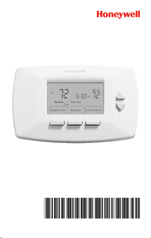
Quick Installation Guide
69-2487EF-01
RTH7400/RTH7500 Series
Programmable Thermostat
Page 2

Advanced Installation Guide
Installation is Easy
Label wires and remove your old thermostat
Install and wire your new thermostat
Set your new thermostat to match your heating/cooling
system
– This thermostat works with virtually all System
Types
– It is preset for the most common system
We are here to help.
Call 1-800-468-1502 for
wiring assistance before
returning the thermostat to
the store.
69-2487EF—01 ii
Page 3
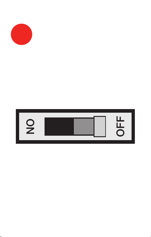
Turn Off Power to Heating/
M28097
1
Cooling System
RTH7400/RTH7500 Series
1 69-2487EF—01
Page 4
Advanced Installation Guide
M28099
Remove Old Thermostat
2
Remove old thermostat but leave wallplate with
wires attached.
MERCURY NOTICE
Is there a sealed tube
Leave wallplate
in place
Old thermostat
Cover
containing mercury? If so,
see back cover for proper
disposal instructions.
69-2487EF—01 2
Page 5
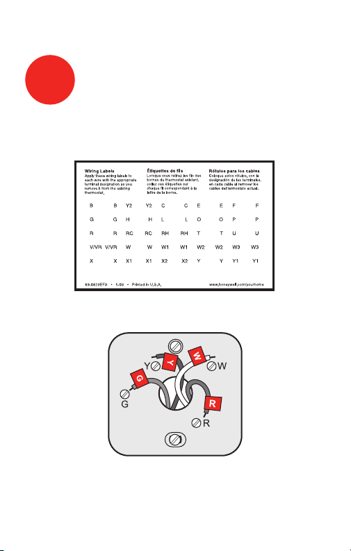
RTH7400/RTH7500 Series
M28100
M28093
Label Wires with Tags
3
Label the wires using the supplied wire labels as you
disconnect them.
Wire Labels
NOTE: Jumper wire used on old thermostat? If yes, note
what letters the jumper connected and review in wiring
section.
3 69-2487EF—01
Page 6
Advanced Installation Guide
M28073
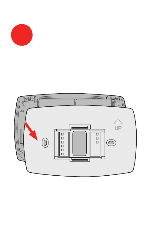
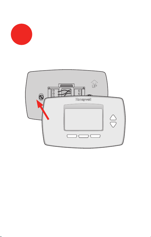
Separate Wallplate from
4
New Thermostat
Remove wallplate from the new thermostat and mount
onto wall.
Wallplate
69-2487EF—01 4
Page 7
RTH7400/RTH7500 Series
M28094
Mount Wallplate
5
Mount the new wallplate using the included screws
and anchors.
Drill 3/32-in. holes for plaster
Drill 3/16-in. holes for drywall
Use hammer to tap the anchors into the wall.
5 69-2487EF—01
Page 8
Advanced Installation Guide
MCR28845
W2
Y2
C
G
Y
W
RC
R
LABELED WIRES
SCREW
CONVENTIONAL
INSERT WIRES
THEN TIGHTEN SCREWS
WIRE HOLE
Y
G
R
W
CONVENTIONAL
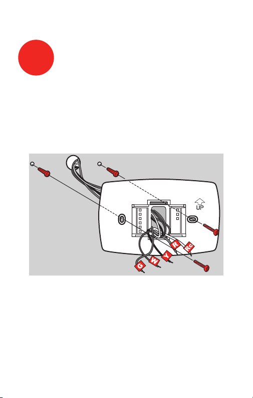
Connect Wires
6
Simply match wire labels.
Remove metal jumper if you have both R and Rc wires.
Labels don’t match? See page 21.
Have a Heat Pump system? See pages 22–23.
We are here to help.
Call 1-800-468-1502 for wiring assistance.
69-2487EF—01 6
Page 9
RTH7400/RTH7500 Series
M28101
M28102
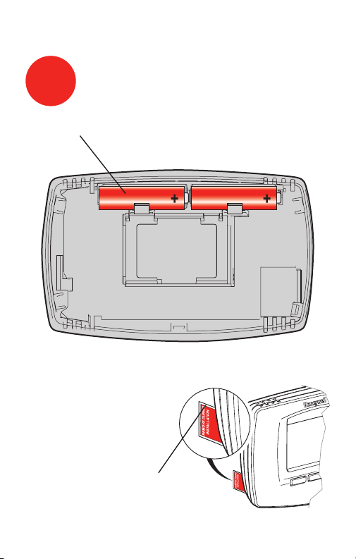
Install Batteries
7
Install two AA alkaline batteries and remove tab.
Back of thermostat
Remove tab.
7 69-2487EF—01
Page 10
Advanced Installation Guide
M28103
Install Thermostat onto Wallplate
8
Install thermostat onto the wallplate on the wall.
69-2487EF—01 8
Page 11
RTH7400/RTH7500 Series
M28098
Turn Power Back On
9
Turn the power back on to the heating/cooling system.
9 69-2487EF—01
Page 12
Advanced Installation Guide
Go Back Next Done
6
15
2006
M28095
Done
10:10
M28096
10
Press s or t to set month, then press NEXT.
Press s or t to set day, then press NEXT.
Press s or t to set year, then press DONE.
Press s or t to set time, then press DONE to save and
exit.
Set Time and Date
Month Year Day
69-2487EF—01 10
Page 13

RTH7400/RTH7500 Series
11
If your system type is...
If your system type is:
q Single Stage Heat and Cool
Congratulations, you’re done!
If your system type is:
q Multistage Heat and Cool
q Heat Pump* without Backup Heat
q Heat Pump* with Backup Heat
q Heat Only
q Cool Only
Continue with advanced installation
on next page to match your thermostat to your sytem type.
*Heat Pump—an air conditioner that provides cooling
in the summer, and also runs in reverse in the winter to
provide heating.
If you are not sure of your system type or if you have
other questions, call us toll-free at 1-800-468-1502.
This thermostat works on 24 volt or 750 mV systems. It
will NOT work on 120/240 Volt systems.
11 69-2487EF—01
Page 14

Advanced Installation
System setup ......................................................................13
Wiring ..................................................................................21
Troubleshooting ..................................................................24
Customer assistance .........................................................26
Limited warranty .................................................................27
Page 15
RTH7400/RTH7500 Series
System & Fan ScheduleClock & More
20
0120
M27459
SystemFan Done
20
0120
M28069
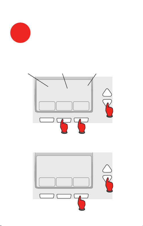
About your new thermostat
System setup
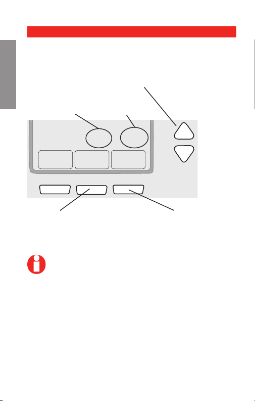
Step 1
Press and release the left button.
Step 2
Press and hold the center button until the screen
changes (approximately 5 seconds).
SETUP WIRING ASSISTANCE TROUBLESHOOTING
13 69-2487EF—01
Page 16
Advanced Installation Guide
Go Back Next Done
20
0120
About your new thermostat
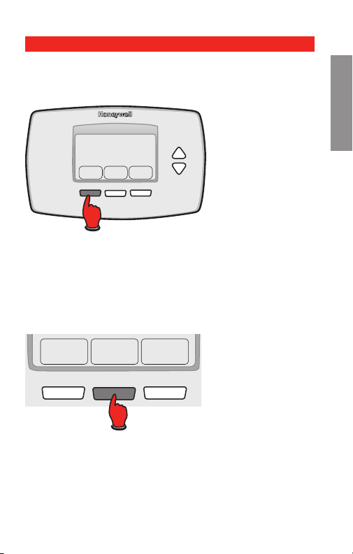
Navigating setting changes
Use this navigation to set and change settings on
pages 15-20.
SETUPWIRINGASSISTANCETROUBLESHOOTING
Press s t to change setting.
Function
Press NEXT to advance to
next function.
NOTE: Some functions in the following pages
may not appear due to previous selections
made.
69-2487EF—01 14
Setting
Press DONE to save &
exit.
Page 17

RTH7400/RTH7500 Series
About your new thermostat
System setup
NOTE: If you set the time and date as shown on
page 10, press NEXT to function 0170 and go to
page 16.
See page 14 to navigate between functions.
Function Settings & Options
0120 Year Setting
(rst two
digits)
0130 Year Setting
(second two
digits)
0140 Month Setting
0150 Date Setting
Press s/t to change the rst two
digits of the year:
20 = Year 20xx
21 = Ye ar 21xx
Press NEXT
Press s/t to change the last two
digits of the year:
01 - 99 (i.e., 2001 - 2099)
Press NEXT
Press s/t to change the current
month:
01 - 12 (i.e., January - December)
Press NEXT
Press s/t to change the current
date:
01 - 31
Press NEXT
SETUP WIRING ASSISTANCE TROUBLESHOOTING
15 69-2487EF—01
Page 18

Advanced Installation Guide
About your new thermostat
System setup
See page 14 to navigate between functions.
Function Settings & Options
0170 Select System
SETUPWIRINGASSISTANCETROUBLESHOOTING
Type
Press s/t to select your system
type:
1 Heat/cool: Gas, oil or electric
heating with central air conditioning.
2 Heat pump: Heat pump with-
out backup or auxiliary heat.
3 Heat only: Gas, oil or electric
heat without central air conditioning.
4 Heat only with fan: Gas, oil or
electric heat without central air
conditioning.
5 Hot water heat only (no fan):
Gas, oil or hot water heat without central air conditioning.
6 Cool only: Central air condi-
tioning only.
7 Heat pump: Heat pump with
backup or auxiliary heating.
8 Heat/Cool Multiple stages:
2 heat stages (wires on W and
W2), 2 cooling stages (wires on
Y and Y2).
9 Heat/Cool Multiple stages:
2 heat stages (wires on W and
W2), 1 cooling stage (wire on
Y).
10 Heat/Cool Multiple stages: 1
heat stage (wire on W), 2 cooling stages (wires on Y and Y2).
Press NEXT
69-2487EF—01 16
Page 19

RTH7400/RTH7500 Series
About your new thermostat
System setup
See page 14 to navigate between functions.
Function Settings & Options
0180 Heating Fan
Control
0190 Heat Pump
Changeover
Valve (for heat
pumps only)
NOTE: Some functions in the following pages
may not appear due to previous selections
made.
Press s/t to select your heating
system & fan control:
0 Gas or oil heat: Use this
setting if you have a gas or
oil heating system (system
controls fan operation).
1 Electric heat: Use this setting
if you have an electric heating
system (thermostat controls fan
operation).
Press NEXT
Press s/t to select whether your
changeover valve is used in heating
or cooling:
0 Cooling changeover valve:
Use this setting if you connected a wire labeled “O” to
the O/B terminal (see page 22).
1 Heating changeover valve:
Use this setting if you connected a wire labeled “B” to the
O/B terminal (see page 23).
Press NEXT
SETUP WIRING ASSISTANCE TROUBLESHOOTING
17 69-2487EF—01
Page 20

Advanced Installation Guide
About your new thermostat
System setup
See page 14 to navigate between functions.
Function Settings & Options
0240 Heating Cycle
SETUPWIRINGASSISTANCETROUBLESHOOTING
Rate
0270 Emergency
Heat Cycle
Rate (heat
pumps only)
NOTE: Some functions in the following pages
may not appear due to previous selections
made.
69-2487EF—01 18
Press s/t to select your heating
system:
5 Gas or oil furnace: Standard
gas/oil furnace (less than 90%
efficiency).
9 Electric furnace: Electric
heating systems.
3 Hot water or high-efficiency
furnace: Hot water system or
gas furnace (more than 90%
efficiency).
1 Gas/oil steam or gravity
system: Steam or gravity heat
systems.
Press NEXT
Press s/t to select your heating
system:
9 Electric furnace: Electric
heating systems.
5 Gas or oil furnace: Standard
gas/oil furnace (less than 90%
efficiency).
3 Hot water or high-efficiency
furnace: Hot water system or
gas furnace (more than 90%
efficiency).
1 Gas/oil steam or gravity
system: Steam or gravity heat
systems.
Press NEXT
Page 21

RTH7400/RTH7500 Series
About your new thermostat
System setup
See page 14 to navigate between functions.
Function Settings & Options
0300 Manual/Auto
Changeover
See Operating Manual for
details.
0320 Temperature
Format (°F/°C)
0330 Daylight
Saving Time
On/Off
NOTE: Some functions in the following pages
may not appear due to previous selections
made.
19 69-2487EF—01
Press s/t to select manual or
automatic changeover:
0 Manual changeover (Heat/Cool/
Off).
1 Automatic changeover (Heat/
Cool/Auto/Off). Automatically
turns on Heat or Cool based
on room temperature. Note:
System maintains minimum 3°F
difference between heat and
cool settings.
Press NEXT
Press s/t to set the temperature
display format:
0 Fahrenheit
1 Celsius
Press NEXT
Press s/t to select an option:
0 Off: No adjustment for daylight
saving time.
1 On: Auto-change to daylight
saving time (for areas that do
not use the new 2007 DST
calendar).
2 On: Auto-change to daylight
saving time (2007 and beyond,
for areas that use the new 2007
DST calendar).
Press NEXT
SETUP WIRING ASSISTANCE TROUBLESHOOTING
Page 22

Advanced Installation Guide
About your new thermostat
System setup
See page 14 to navigate between functions.
Function Settings & Options
0500 Furnace Filter
SETUPWIRINGASSISTANCETROUBLESHOOTING
Change
Reminder
0530 Smart
Response®
Technology
0640 Clock Format
Press s/t to set the desired
reminder interval:
0 Off (no reminder)
1 Reminder in about 1 month
2 Reminder in about 3 months
3 Reminder in about 6 months
4 Reminder in about 9 months
5 Reminder in about 1 year
6 Reminder in about 3 years
Press NEXT
Press s/t to turn this feature on or
off (see Operating Manual for more
information about this feature):
1 On
0 Off
Press NEXT
Press s/t to set the clock display
format:
12 12-hour clock (i.e., “3:30 pm”)
24 24-hour clock (i.e., “15:30”)
Press DONE to save and exit setup.
Congratulations, you’re done!
69-2487EF—01 20
Page 23

RTH7400/RTH7500 Series
C
G
Y
W
RC
R
W2
Y2
Y2
W2
W
Y
G
MCR32160
R
2
Rc
2
C
3
About your new thermostat
Wiring—conventional system
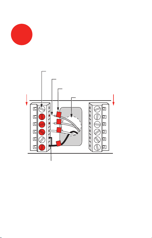
Alternate wiring (conventional systems)
If labels do not match terminals, connect wires as
shown here (see notes, below).
SETUP WIRING ASSISTANCE TROUBLESHOOTING
Remove metal jumper connecting R and Rc only
if you must connect both R and Rc wires.
If your old thermostat had both R and RH wires,
remove metal jumper. Connect the R wire to the
Rc terminal, and the RH wire to the R terminal.
If your old thermostat had only 1 C or C1
wire, connect it to the C terminal. If your old
thermostat had 2 C or C1 wires, wrap each
separately with electrical tape and do not
connect them.
21 69-2487EF—01
Page 24

Advanced Installation Guide
C
G
Y
O/B
RC
R
HEAT PUMP
MCR28104A
Aux
E
L
LABELED WIRES
SCREW
INSERT WIRES
THEN TIGHTEN SCREWS
WIRE HOLE
Y
G
R
O
HEAT PUMP
Aux
About your new thermostat
Wiring—heat pump
Connect wires: Heat Pump
1. Match each labeled wire with same letter on new
thermostat.
SETUPWIRINGASSISTANCETROUBLESHOOTING
2. Use a screwdriver to loosen screws, insert wires into
hole under screw, then tighten screws until wire is
secure.
3. If E and Aux do not each have a wire connected,
use a small piece of wire to connect them to each
other.
4. Push any excess wire back into the wall opening.
Labels don’t match?
If labels do not match letters on thermostat, see page
23.
Wiring complete, return to Step 7.
69-2487EF—01 22
Page 25

RTH7400/RTH7500 Series
5
6
2
3
5
3 5
4
6
6
MCR32161
C
G
Y
O/B
RC
R
AUX
E
L
Wiring—heat pump
Alternate wiring (for heat pumps only)
Leave metal jumper in place, connecting R & Rc
terminals.
If your old thermostat had both V and VR wires,
stop now and contact a qualified contractor for
help.
If your old thermostat had separate O and B
wires, attach the B wire to the C terminal. If
another wire is attached to the C terminal, stop
now and contact a qualified contractor for help.
If your old thermostat had Y1, W1 and W2 wires,
stop now and contact a qualified contractor for
help.
If L terminal is used, C terminal wire must be
connected (contact a contractor if there is no C
wire).
If E and Aux terminals do not each have a wire
connected, use a small piece of wire to connect
them to each other.
Wiring complete, return to Step 7.
23 69-2487EF—01
SETUP WIRING ASSISTANCE TROUBLESHOOTING
Page 26

Advanced Installation Guide
Troubleshooting
If you have difficulty with your thermostat, please try
the following suggestions.
Most problems can be corrected quickly and easily.
Display is blank
SETUPWIRINGASSISTANCETROUBLESHOOTING
Cannot change
system setting
to Cool
Fan does not
turn on when
heat is required
Heating system
is running in
cool mode
Red light is on
Make sure fresh AA alkaline batteries
are properly installed (see
page 7).
Check Function 0170: System Type
to make sure it is set to match your
heating and cooling equipment (see
page 16).
Check Function 0180: Heating Fan
Control to make sure it is set to match
your heating equipment (see page 17).
Check Function 0170: System Type
to make sure it is set to match your
heating and cooling equipment (see
page 16).
If thermostat is in Emergency Heat
mode the red light is normal. It shows
that the thermostat is in emergency
heat mode.
If thermostat is not in Emergency Heat
mode, contact a qualied service contractor for repair.
69-2487EF—01 24
Page 27

Troubleshooting
Heating or cooling system does
not respond
RTH7400/RTH7500 Series
Press SYSTEM to set system to Heat.
Make sure the temperature is set higher
than the Inside temperature.
Press SYSTEM to set system to Cool.
Make sure the temperature is set lower
than the Inside temperature.
Check circuit breaker and reset if
necessary.
Make sure power switch at heating &
cooling system is on.
Make sure furnace door is closed
securely.
Wait 5 minutes for the system to
SETUP WIRING ASSISTANCE TROUBLESHOOTING
“Wait” appears
on the screen
Heat pump issues cool air in
heat mode, or
warm air in cool
Compressor protection feature is
engaged. Wait 5 minutes for the system
to restart safely, without damage to the
compressor.
Check Function 0190: Heat Pump
Changeover Valve to make sure it is
properly congured for your system
(see page 17).
mode
25 69-2487EF—01
Page 28

Advanced Installation Guide
Customer assistance
For assistance with this product, please visit
http://yourhome.honeywell.com
or call Honeywell Customer Care toll-free at
SETUPWIRINGASSISTANCETROUBLESHOOTING
1-800-468-1502.
69-2487EF—01 26
Page 29

RTH7400/RTH7500 Series
1-year limited warranty
Honeywell warrants this product, excluding battery, to be free
from defects in the workmanship or materials, under normal use
and service, for a period of one (1) year from the date of purchase
by the consumer. If at any time during the warranty period the
product is determined to be defective or malfunctions, Honeywell
shall repair or replace it (at Honeywell’s option).
If the product is defective,
(i) return it, with a bill of sale or other dated proof of purchase, to
the place from which you purchased it; or
(ii) call Honeywell Customer Care at 1-800-468-1502. Customer
Care will make the determination whether the product should be
returned to the following address: Honeywell Return Goods, Dock
4 MN10-3860, 1985 Douglas Dr. N., Golden Valley, MN 55422, or
whether a replacement product can be sent to you.
This warranty does not cover removal or reinstallation costs. This
warranty shall not apply if it is shown by Honeywell that the defect
or malfunction was caused by damage which occurred while the
product was in the possession of a consumer.
Honeywell’s sole responsibility shall be to repair or replace the
product within the terms stated above. HONEYWELL SHALL
NOT BE LIABLE FOR ANY LOSS OR DAMAGE OF ANY KIND,
INCLUDING ANY INCIDENTAL OR CONSEQUENTIAL DAMAGES
RESULTING, DIRECTLY OR INDIRECTLY, FROM ANY BREACH
OF ANY WARRANTY, EXPRESS OR IMPLIED, OR ANY OTHER
FAILURE OF THIS PRODUCT. Some states do not allow the exclusion or limitation of incidental or consequential damages, so this
limitation may not apply to you.
THIS WARRANTY IS THE ONLY EXPRESS WARRANTY
HONEYWELL MAKES ON THIS PRODUCT. THE DURATION OF
ANY IMPLIED WARRANTIES, INCLUDING THE WARRANTIES
OF MERCHANTABILITY AND FITNESS FOR A PARTICULAR
PURPOSE, IS HEREBY LIMITED TO THE ONE-YEAR DURATION
OF THIS WARRANTY.
Some states do not allow limitations on how long an implied warranty lasts, so the above limitation may not apply to you. This
warranty gives you specific legal rights, and you may have other
rights which vary from state to state.
If you have any questions concerning this warranty, please
write Honeywell Customer Relations, 1985 Douglas Dr, Golden
Valley, MN 55422 or call 1-800-468-1502. In Canada, write Retail
Products ON15-02H, Honeywell Limited/ Honeywell Limitée, 35
Dynamic Drive, Toronto, Ontario M1V4Z9.
27 69-2487EF—01
Page 30

This thermostat contains a Lithium battery which may
contain Perchlorate material.
Perchlorate Material—special handling may apply,
See www.dtsc.ca.gov/hazardouswaste/perchlorate
MERCURY NOTICE: Do not place your old
thermostat in the trash if it contains mercury
in a sealed tube. Contact your local waste
management authority for instructions regarding
recycling and proper disposal.
CAUTION: To avoid possible compressor
damage, do not run air conditioner if the outside
temperature drops below 50°F (10°C).
Automation and Control Solutions
Honeywell International Inc.
1985 Douglas Drive North
Golden Valley, MN 55422
Honeywell Limited-Honeywell Limitée
35 Dynamic Drive
Toronto, Ontario M1V 4Z9
yourhome.honeywell.com
® U.S. Registered Trademark.
© 2010 Honeywell International Inc.
69-2487EF—01 M.S. 06-10
Printed in U.S.A.
Page 31

Guide d’installation rapide
69-2487EF-01
Série RTH7400/RTH7500
Thermostat programmable
Page 32

Guide d’installation rapide
L’installation est facile !
Étiquetage des fils et retrait de l’ancien thermostat
Installation et raccordement du nouveau thermostat
Configuration du nouveau thermostat pour
correspondre à votre système de chauffage/
climatisation
– Ce thermostat fonctionne avec pratiquement
tous les types de systèmes
– Il est préréglé en prévision des systèmes les plus
communs
Nous sommes à votre service.
Composer le 1-800-468-
1502 pour obtenir de l’aide
au raccordement avant de
retourner le thermostat au
magasin.
69-2487EF—01 ii
Page 33

Couper le courant du système
M28097
1
de chauffage/de climatisation
Série RTH7400/RTH7500
1 69-2487EF—01
Page 34

Guide d’installation rapide
M28099
Retirer l’ancien thermostat
2
Retirer l’ancien thermostat, mais laisser en place la plaque
murale et les fils sans les détacher.
REMARQUE À PROPOS DU
MERCURE
Y a-t-il une ampoule contenant
du mercure? Si c’est le cas,
se reporter aux consignes
Laisser la plaque
de montage en
place
figurant sur la couverture avant
de ce livret pour connaître
les règlements concernant
l’élimination.
Ancien thermostat
Couvercle
69-2487EF—01 2
Page 35

Série RTH7400/RTH7500
M28100
M28093
Étiqueter les fils
3
Étiqueter les fils à l’aide des étiquettes fournies à mesure
que les fils sont débranchés.
Étiquettes de fils
REMARQUE : Fil cavalier utilisé sur l’ancien thermostat?
Si c’est le cas, noter les lettres du cavalier connecté et
consulter la section relative au câblage.
3 69-2487EF—01
Page 36

Guide d’installation rapide
M28073
Séparer la plaque murale du
4
nouveau thermostat
Retirer la plaque murale du nouveau thermostat et
l’installer au mur.
Plaque de montage
69-2487EF—01 4
Page 37

Série RTH7400/RTH7500
M28094
Installer la plaque
5
Installer la nouvelle plaque murale à l’aide des vis et des
chevilles d’ancrage fournies.
Percer des trous de 3/32 po si le mur est en plâtre
Percer des trous de 3/16 po si le mur est en placoplâtre
Utiliser un marteau pour enfoncer les ancres dans le mur.
5 69-2487EF—01
Page 38

Guide d’installation rapide
MCRF28104
Aux
E
L
C
G
Y
O/B
RC
R
FILS ÉTIQUETÉS
VIS
THERMOPOMPE
INSÉRER LES FILS,
PUIS SERRER LES VIS
OUVERTURE
POUR LES FILS
Y
G
R
Aux
O
THERMOPOMPE
Raccorder les fils
6
Il suffit ensuite de faire correspondre les fils avec les
étiquettes.
Retirer le cavalier en métal s’il y a à la fois
les fils « R » et « Rc ».
Les étiquettes ne correspondent pas? Voir page 21.
Avez-vous une thermopompe? Voir pages 22–23.
Nous sommes à votre service.
Composer le 1-800-468-1502 pour obtenir de l’aide
au cours du raccordement.
69-2487EF—01 6
Page 39

Série RTH7400/RTH7500
M28101
M28102
Installer les piles
7
Installer 2 piles alcalines AA à l’arrière du thermostat et
retirer l’onglet.
Dos du thermostat
Retirer l’onglet.
7 69-2487EF—01
Page 40

Guide d’installation rapide
M28103
Fixer le thermostat à la plaque
8
murale
Installer le thermostat sur la plaque murale fixée au mur.
69-2487EF—01 8
Page 41

Série RTH7400/RTH7500
M28098
Rétablir l’alimentation
9
électrique
Rétablir l’alimentation électrique du système de
chauffage-refroidissement.
9 69-2487EF—01
Page 42

Guide d’installation rapide
Go Back Next Done
6
15
2006
M28095
Done
10:10
M28096
10
Appuyer sur s ou t pour régler le mois, puis appuyer sur NEXT.
Appuyer sur s ou t pour régler la date, puis appuyer sur NEXT.
Appuyer sur s ou t pour régler l’année, puis appuyer sur DONE.
Appuyer sur s ou t pour régler l’heure puis appuyer sur
DONE pour sauvegarder et quitter.
Régler l’heure et date
Mois Année Date
69-2487EF—01 10
Page 43

Série RTH7400/RTH7500
Si votre système est du type
11
suivant...
Si votre système est du type suivant :
q Chauffage et refroidissement à un étage
Félicitations, vous avez terminé!
Si votre système est du type suivant :
q Chauffage et refroidissement, multiétages
q Thermopompe* sans chauffage d’appoint
q Thermopompe* avec chauffage d’appoint
q Chauffage seulement
q Refroidissement seulement
Passez au mode d’installation avancé
à la page suivante pour faire correspondre le
thermostat à votre type de système.
*Thermopompe—climatiseur qui procure de l’air froid en
été et qui fonctionne à l’inverse en hiver pour assurer le
chauffage.
Si vous n’êtes pas certain de connaître votre type de
système, composez sans frais le 1-800-468-1502.
Ce thermostat convient aux systèmes alimentés par du
courant 24 volts ou 750 millivolts. Il ne convient pas aux
systèmes alimentés par du courant 120/240 volts.
11 69-2487EF— 01
Page 44

Guide d’installation avancé
Modification des réglages .................................................13
Câblage ...............................................................................21
Dépannage .........................................................................24
Assistance à la clientèle ....................................................26
Garantie limitée ..................................................................26
Page 45

Série RTH7400/RTH7500
System & Fan ScheduleClock & More
20
0120
M27459
SystemFan Done
20
0120
M28069
About your new thermostat
Modification des réglages
Étape 1
Appuyer sur le bouton de gauche puis le relâcher.
Étape 2
Appuyer sur le bouton du centre jusqu’à ce que
l’affichage change (environ 5 secondes).
RÉGLAGE WIRING ASSISTANCE TROUBLESHOOTING
13 69-2487EF—01
Page 46

Guide d’installation avancé
Go Back Next Done
20
0120
Navigation pour modifier les réglages
Utiliser cette navigation pour définir et modifier les
réglages aux pages 15-20.
Appuyer sur s t pour modifier les paramètres.
RÉGLAGEWIRINGASSISTANCETROUBLESHOOTING
Fonction
Appuyer sur NEXT pour
sélectionner la fonction.
REMARQUE : Certaines fonctions décrites
dans les pages suivantes peuvent ne pas apparaître en raison des choix faits aux étapes précédentes.
69-2487EF—01 14
Réglage
Appuyer sur DONE pour
sauvegarder et quitter.
Page 47

Série RTH7400/RTH7500
Modification des réglages
REMARQUE : Si l’heure et la date sont réglées
selon les directives à la page 10, appuyer sur
NEXT à la fonction 0170 et
passer à la page 16.
Voir page 14 pour naviguer entre les différentes fonctions.
Fonction Réglages et options
0120 Programma-
tion de l’année
(deux premiers
chiffres)
0130 Programma-
tion de l’année
(deux derniers
chiffres)
0140 Programma-
tion du mois
0150 Programma-
tion de la date
Appuyer sur s/t pour modier les
deux premiers chiffres de l’année :
20 = Année 20xx
21 = Année 21xx
Appuyer sur NEXT
Appuyer sur s/t pour modier les
deux derniers chiffres de l’année :
01 - 99 (c.-à-d. 2001 - 2099)
Appuyer sur NEXT
Appuyer sur s/t pour modier le
mois en cours af ché :
01 - 12 (c.-à-d. janvier-décembre)
Appuyer sur NEXT
Appuyer sur s/t pour modier a
la date :
01 - 31
Appuyer sur NEXT
RÉGLAGE WIRING ASSISTANCE TROUBLESHOOTING
15 69-2487EF—01
Page 48

Guide d’installation avancé
Modification des réglages
Voir page 14 pour naviguer entre les différentes fonctions.
Fonction Réglages et options
0170 Type de
système
RÉGLAGEWIRINGASSISTANCETROUBLESHOOTING
Appuyer sur s/t pour choisir votre
type de système :
1 Chauff./Clim. : Gaz, mazout
ou chauffage électrique avec
climatisation.
2 Thermopompe : 1 chauffage
(sans de chauffage aux.).
3 Chauff. seulement : Gaz,
mazout ou chauffage électrique
sans climatisation.
4 Chauffage seulement avec
ventilateur (gaz, mazout ou
chauffage électrique).
5 Chauff. eau chaude sans
ventilateur (gaz, mazout ou
chauffage eau chaude).
6 Climatisation centrale
seulement.
7 Thermopompe (avec chauffage
aux.).
8 Multi-étages : 2 étages de
chauffage (fils W et W2), 2
étages de climatisation (fils Y et
Y2).
9 Multi-étages : 2 étages de
chauffage (fils sur W et W2), 1
étage de climatisation (fil Y).
10 Multi-étages : 1 étage de
chauffage (fil W), 2 étages de
climatisation (fils Y et Y2).
Appuyer sur NEXT
69-2487EF—01 16
Page 49

Série RTH7400/RTH7500
Modification des réglages
Voir page 14 pour naviguer entre les différentes fonctions.
Fonction Réglages et options
0180 Commande du
ventilateur de
chauffage
0190 Vanne
d’inversion
(pour thermopompes seulement)
REMARQUE : Certaines fonctions décrites
dans les pages suivantes peuvent ne pas
apparaître en raison des choix faits aux étapes
précédentes.
Appuyer sur s/t pour choisir le
système de chauffage/ventilateur :
0 Chauffage gaz/mazout :
Système gaz/mazout (Le
système commande le
fonctionnement du ventilateur).
1 Chauffage électrique : (Le
thermostat commande le
fonctionnement du ventilateur).
Appuyer sur NEXT
Appuyer sur s/t pour choisir si la
vanne d’inversion est utilisée dans
le chauffage ou le climatisation :
0 Vanne de climatisation :
Utiliser ce réglage si le fil
étiqueté «O» a été raccordé à la
borne O/B (voir la page 22).
1 Vanne de chauffage : Utiliser
ce réglage si le fil étiqueté «B»
a été raccordé à la borne O/B
(voir la page 23).
Appuyer sur NEXT
RÉGLAGE WIRING ASSISTANCE TROUBLESHOOTING
17 69-2487EF—01
Page 50

Guide d’installation avancé
Modification des réglages
Voir page 14 pour naviguer entre les différentes fonctions.
Fonction Réglages et options
0240 Longueur
des cycles de
RÉGLAGEWIRINGASSISTANCETROUBLESHOOTING
chauffage
0270 Longueur
des cycles de
chauffage de
secours (thermopompes
seulement)
REMARQUE : Certaines fonctions décrites
dans les pages suivantes peuvent ne pas
apparaître en raison des choix faits aux étapes
précédentes.
69-2487EF—01 18
Appuyer sur s/t pour choisir le
type de système de chauffage :
5 Système de chauffage
standard au gaz ou au
mazout - efficacité à moins de
90 %
9 Systèmes de chauffage
électriques
3 Système de chauffage à eau
chaude ou au gaz efficacité à plus de 90 %.
1 Système de chauffage au
gaz ou au mazout : Vapeur ou
gravité
Appuyer sur NEXT
Appuyer sur s/t pour choisir votre
type de système de chauffage :
9 Systèmes de chauffage
électriques
5 Système de chauffage
standard au gaz ou au
mazout - efficacité à moins de
90 %
3 Système de chauffage à eau
chaude ou au gaz - efficacité
à plus de 90 %.
1 Système de chauffage au gaz
ou au mazout : Vapeur ou
gravité
Appuyer sur NEXT
Page 51

Série RTH7400/RTH7500
Modification des réglages
Voir page 14 pour naviguer entre les différentes fonctions.
Fonction Réglages et options
0300 L’inversion
manuel ou
automatique
Voir le manuel
de l’opérateur
pour les
détails.
0320 Format de la
température
(°F/°C)
0330 Changement
horaire été
REMARQUE : Certaines fonctions décrites
dans les pages suivantes peuvent ne pas
apparaître en raison des choix faits aux étapes
précédentes.
19 69-2487EF—01
Appuyer sur s/t pour choisir
l’inversion manuelle ou automatique :
0 L’inversion manuel (Heat/Cool/
Off).
1 L’inversion automatique (Heat/
Cool/Auto/Off). Remarque :
le système maintient un écart
minimal de 3 ˚F entre les
réglages du chauffage et du
refroidissement.
Appuyer sur NEXT
Appuyer sur s/t pour choisir le
format de la température :
0 Fahrenheit
1 Celsius
Appuyer sur NEXT
Appuyer sur s/t pour choisir une
option :
0 OFF : L’horaire d’été est
désactivé.
1 ON : Changement automatique
à l’heure avancée (pour les
zones qui n’utilisent pas le
nouveau calendrier d’heure
avancée de 2007)
2 ON : Changement automatique
à l’heure avancée (pour les
zones qui utilisent le nouveau
calendrier d’heure avancée
de 2007 et des années
subséquentes)
Appuyer sur NEXT
RÉGLAGE WIRING ASSISTANCE TROUBLESHOOTING
Page 52

Guide d’installation avancé
Modification des réglages
Voir page 14 pour naviguer entre les différentes fonctions.
Fonction Réglages et options
0500 Rappel de
RÉGLAGEWIRINGASSISTANCETROUBLESHOOTING
changement
du ltre du
système de
chauffage
0530 Technologie
Smart
Response®
(marche/arrêt)
0640 Format de
l’heure
Appuyer sur s/t pour choisir
l’intervalle désiré de rappel :
0 Arrêt (pas de rappel de change-
ment de filtre du système de
chauffage).
1 Rappel après 1 mois.
2 Rappel après 3 mois.
3 Rappel après 6 mois.
4 Rappel après 9 mois.
5 Rappel après 1 an.
6 Rappel après 3 ans.
Appuyer sur NEXT
Appuyer sur s/t pour activer
ou désactiver cette fonction (voir
le guide d’utilisation pour plus
d’information) :
1 Marche
0 Arrêt
Appuyer sur NEXT
Appuyer sur s/t pour choisir le
format de l’heure :
12 Horloge 12 heures (3:30 pm)
24 Horloge 24 heures (15:30)
Appuyer sur DONE (TERMINÉ) pour
enregistrer les modifications et quitter le
mode de réglage.
Félicitations, vous avez terminé!
69-2487EF—01 20
Page 53

Série RTH7400/RTH7500
C
G
Y
W
RC
R
W2
Y2
Y2
W2
W
Y
G
MCRF32160
R
2
Rc
2
C
3
Câblage—systèmes classiques
Câblage alternatif (systèmes classiques)
Si les étiquettes ne correspondent pas aux bornes,
les raccorder comme l’indique l’explication ci-dessous
(voir les notes ci-dessous).
Enlever le cavalier en métal en métal entre R
et Rc seulement si les fils R et Rc doivent être
raccordés.
Si l’ancien thermostat avait les deux fils R et RH,
retirer le cavalier de métal. Raccorder le fil R à
la borne Rc et le fil RH à la borne R.
Si l’ancien thermostat avait seulement un fil C
ou C1, le raccorder à la borne C. Si l’ancien
thermostat avait 2 fils C ou C1, enrubanner
chacun des fils séparément avec du ruban
isolant et ne pas les raccorder.
21 69-2487EF— 01
SETUP CÂBLAGE ASSISTANCE TROUBLESHOOTING
Page 54

Guide d’installation avancé
MCRF28104
Aux
E
L
C
G
Y
O/B
RC
R
FILS ÉTIQUETÉS
VIS
THERMOPOMPE
INSÉRER LES FILS,
PUIS SERRER LES VIS
OUVERTURE
POUR LES FILS
Y
G
R
Aux
O
THERMOPOMPE
Câblage—thermopompe
Raccorder les fils : Thermopompe
1. Faire correspondre chaque fil étiqueté à la même lettre
sur le nouveau thermostat.
SETUPCÂBLAGEASSISTANCETROUBLESHOOTING
2. Utiliser un tournevis pour desserrer les vis, insérer
les fils dans l’orifice sous la vis, puis serrer les vis
pour maintenir les fils.
3. Si les bornes E et Aux ne sont raccordées à aucun
fil, utiliser un bout de fil pour les raccorder l’une à
l’autre.
4. Repousser le fil en excès dans l’ouverture dans le mur.
Les étiquettes ne correspondent pas?
Si les étiquettes ne correspondent pas aux lettres
marquées sur le thermostat, se reporter à la page 23.
Câblage terminé, revenir à l’étape 7.
69-2487EF—01 22
Page 55

Série RTH7400/RTH7500
5
6
2
3
5
3 5
4
6
6
MCRF32161
C
G
Y
O/B
RC
R
AUX
E
L
Câblage—thermopompe
Câblage alternatif (pour thermopompes seulement)
Laisser le cavalier en place, en reliant les bornes
R et Rc.
Si l’ancien thermostat avait des fils de V et de
VR, arrêter maintenant et communiquer avec un
entrepreneur pour l’aide.
Si l’ancien thermostat avait les fils O et B,
raccorder le fil B à la borne C. Si un autre fil est
raccordé à la borne C, arrêter maintenant et
communiquer avec un entrepreneur.
Si l’ancien thermostat avait les fils Y1, W1 et
W2, arrêter maintenant et communiquer avec un
entrepreneur.
Si la borne L est utilisée, le fil de la borne
C doit être raccordé (communiquer avec un
entrepreneur s’il n’y a aucun fil C).
Si chacune des bornes E et Aux n’est pas
raccordée à un fil, utiliser un petit morceau de fil
pour les raccorder entre elles.
Câblage terminé, revenir à l’étape 7.
23 69-2487EF— 01
SETUP CÂBLAGE ASSISTANCE TROUBLESHOOTING
Page 56

Guide d’installation avancé
Dépannage
Si vous éprouvez des difficultés, nous vous proposons
d’essayer les solutions suivantes. La plupart des
problèmes peuvent être corrigés rapidement et
facilement.
SETUPWIRINGASSISTANCEDÉPANNAGE
Rien n’apparaît
à l’écran
Impossible
de changer
le réglage du
système à
climatisation
Ventilateur ne
démarre pas
lors de l’appel
de chauffage
Chauffage
fonctionne
en mode
climatisation
Le voyant rouge
est allumé
Vérier si des piles alcalines AA neuves
sont correctement installées (voir page
7).
Vérier la Fonction 170 : Type
d’installation pour s’assurer que le
réglage correspond aux systèmes de
chauffage et de climatisation (voir page
16).
Vérier la Fonction 180 : Commande du
ventilateur de chauffage pour s’assurer
que le réglage correspond au système
de chauffage (voir page 17).
Vérier la Fonction 170 : Type de
système pour s’assurer que le réglage
correspond aux systèmes de chauffage
ou de climatisation (voir page 16).
Si le thermostat est en mode de la
chaleur de secours la lumière rouge est
normale. Elle prouve que le thermostat
est en mode de la chaleur de secours.
Si le thermostat n’est pas en mode
de la chaleur de secours, entrez en
contact avec un entrepreneur qualié
de service pour la réparation.
69-2487EF—01 24
Page 57

Dépannage
Le système de
chauffage ou de
climatisation ne
répond pas
« Wait » apparaît
sur l’écran
Thermopompe
émet de l’air
froid en mode
chauffage et
de l’air chaud
en mode
climatisation
Série RTH7400/RTH7500
Appuyer sur SYSTEM pour congurer le
système à chauffage (Heat). S’assurer
que le réglage de la température est
supérieur à la température intérieure.
Appuyer sur SYSTEM pour congurer
le système à climatisation (Cool).
S’assurer que le réglage de la
température est inférieur à la
température intérieure.
Vérier si le disjoncteur et le
réenclencher au besoin.
Vérier si l’interrupteur d’alimentation
du système de chauffage et de
climatisation est à la position de
marche.
Vérier si la porte de l’appareil de
chauffage est bien fermée.
Attendre 5 minutes pour que le système
se remette en marche.
La fonction de protection du
compresseur est engagée. Attendre
5 minutes pour que le système
redémarre sans risque d’endommager le
compresseur.
Vérier la Fonction 190 : Vanne
d’inversion de la thermopompe pour
s’assurer qu’elle est congurée pour
convenir au système (voir page 17).
SETUP WIRING ASSISTANCE DÉPANNAGE
25 69-2487EF— 01
Page 58

Guide d’installation avancé
Assistance à la clientèle
Pour obtenir de l’aide sur ce produit Honeywell, veuillez
consulter le site
http://yourhome.honeywell.com ou vous adresser
SETUPWIRINGASSISTANCETROUBLESHOOTING
sans frais aux Services à la clientèle de Honeywell au
1 800 468-1502.
Garantie limitée de un an
Honeywell garantit ce produit, à l’exception des piles, contre
tout vice de fabrication ou de matière dans la mesure où il en
est fait une utilisation et un entretien convenables, et ce, pour
un (1) an à partir de la date d’achat par le consommateur. En
cas de défectuosité ou de mauvais fonctionnement pendant
la période de garantie, Honeywell remplacera ou réparera le
produit (au gré de Honeywell) dans un délai raisonnable.
Si le produit est défectueux,
(i) le retourner, accompagné d’une preuve d’achat indiquant la
date d’achat, au détaillant auprès de qui il a été acheté, ou
(ii) l’emballer avec soin, accompagné d’une preuve d’achat
indiquant la date d’achat et d’une brève description du
mauvais fonctionnement, et l’envoyer par la poste, port payé, à
l’adresse suivante :
Honeywell Return Goods
Dock 4 MN10-3860
1985 Douglas Dr N
Golden Valley, MN 55422
69-2487EF—01 26
Page 59

RTH7400/RTH7500 Series
Garantie limitée de un an
La présente garantie ne couvre pas les frais de retrait ou de
réinstallation. La présente garantie ne s’appliquera pas s’il est
démontré que la défectuosité ou le mauvais fonctionnement est
dû à un endommagement du produit alors que le consommateur
l’avait en sa possession.
La responsabilité de Honeywell se limite à réparer ou à remplacer
le produit conformément aux modalités susmentionnées.
HONEYWELL N’EST EN AUCUN CAS RESPONSABLE DES
PERTES OU DOMMAGES, Y COMPRIS LES DOMMAGES
INDIRECTS OU ACCESSOIRES DÉCOULANT DIRECTEMENT
OU INDIRECTEMENT D’UNE VIOLATION QUELCONQUE D’UNE
GARANTIE, EXPRESSE OU TACITE, APPLICABLE AU PRÉSENT
PRODUIT NI DE TOUTE AUTRE DÉFECTUOSITÉ DU PRÉSENT
PRODUIT. Certaines provinces ne permettent pas l’exclusion
ou la restriction des dommages indirects et, par conséquent, la
présente restriction peut ne pas s’appliquer.
LA PRÉSENTE GARANTIE TIENT LIEU DE TOUTES LES AUTRES
GARANTIES, EXPRESSES OU TACITES, ET LES GARANTIES
DE VALEUR MARCHANDE ET DE CONFORMITÉ À UNE FIN
PARTICULIÈRE SONT PAR LES PRÉSENTES EXCLUES APRÈS LA
PÉRIODE DE UN AN DE LA PRÉSENTE GARANTIE
Certaines provinces ne permettent pas de limiter la durée des
garanties tacites et, par conséquent, la présente limitation peut
ne pas s’appliquer. La présente garantie donne au consommateur
des droits légaux spécifiques et peut-être certains autres droits
qui peuvent varier d’une province à l’autre.
Pour toute question concernant la présente garantie, prière
d’écrire aux Services à la clientèle de Honeywell à l’adresse
suivante : Honeywell Customer Relations, 1985 Douglas Drive,
Golden Valley, MN 55422, ou encore composer le 1-800-468-1502.
Au Canada, prière de s’adresser au service des Produits de détail,
Honeywell Limited/Honeywell Limitée, 35 Dynamic Drive, Toronto
(Ontario) M1V 4Z9.
27 69-2487EF—01
Page 60

Ce thermostat contient une pile au lithium qui pourrait
contenir du perchlorate.
Matériau contenant du perchlorate — des consignes de
manipulation spéciales pourraient s'appliquer, prière de
consulter www.dtsc.ca.gov/hazardouswaste/perchlorate
AVIS CONCERNANT LE MERCURE : Si le
présent thermostat remplace un thermostat
contenant du mercure dans une ampoule scellée,
ne pas jeter l’ancien thermostat à la poubelle.
Communiquer avec le service local de cueillette
des déchets pour obtenir de l’information sur
le recyclage ou sur la bonne façon de disposer
d’un ancien régulateur contenant un contact à
mercure.
MISE EN GARDE : Pour éviter d’endommager
le compresseur, ne pas faire fonctionner le
climatiseur si la température extérieure est
inférieure à inférieure à 10 ºC (50 ºF).
Solutions de régulation et d’automatisation
Honeywell International Inc.
1985 Douglas Drive North
Golden Valley, MN 55422
Honeywell Limited-Honeywell Limitée
35 Dynamic Drive
Toronto (Ontario) M1V 4Z9
yourhome.honeywell.com
® Marque de commerce déposée aux É.-U.
© 2010 Honeywell International Inc.
69-2487EF—01 M.S. 06-10
Imprimé aux États-Unis
 Loading...