

Page 1
User Guide
Wi-Fi Programmable
Thermostat
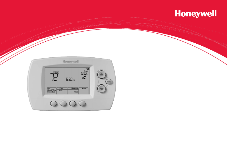
RTH6500WF Wi-Fi Series
Page 2
In the box you will find
• Thermostat
• Wallplate (attached to thermostat)
• Screws and anchors
• Quick Start Guide
• Thermostat ID Card
• Wire labels
• User Guide
• Quick Reference Card
69-2718EF—03 ii
Page 3

Welcome
Congratulations on your purchase of a
Honeywell Wi-Fi programmable thermostat.
When registered to Honeywell’s Total Connect
Comfort Solutions, you can remotely monitor
and control the heating and cooling system
in your home or business—you can stay
connected to your comfort system wherever
you go.
Honeywell’s Total Connect Comfort is the
perfect solution if you travel frequently, own
a vacation home, a business or manage an
Investment property or if you are simply looking
for peace of mind.
Page 4

This thermostat works with common 24 volt systems such as forced air, hydronic,
heat pump, oil, gas, and electric. It will not work with millivolt systems, such as a gas
fireplace, or with 120/240 volt systems such as baseboard electric heat.
MERCURY NOTICE: Do not place your old thermostat in the trash if it contains
mercury in a sealed tube. Contact the Thermostat Recycling Corporation at
www.thermostat-recycle.org or 1-800-238-8192 for information on how and
where to properly and safely dispose of your old thermostat.
NOTICE: To avoid possible compressor damage, do not run air conditioner if the
outside temperature drops below 50°F (10°C).
Need help?
Visit wifithermostat.com or call 1-855-733-5465 for assistance before returning the
thermostat to the store.
69-2718EF—03 2
Page 5

Table of contents
About your new thermostat
Controls and Home screen
quick reference ............................................5
Preset energy-saving schedules ................. 6
Installation
Installing your thermostat ............................ 8
Connecting to your Wi-Fi network .............26
Registering your thermostat online ........... 31
Operation
Setting the the time and day ..................... 36
Setting the fan ........................................... 37
Selecting system mode ............................. 38
Adjusting program schedules .................... 39
Overriding schedules temporarily .............40
Overriding schedules permanently ........... 41
69-2718EF—03 3
Unregistering thermostat........................... 42
Disconnecting Wi-Fi .................................. 43
Special features ........................................45
Setting functions and options ....................48
Appendices
Frequently asked questions ......................55
Troubleshooting .........................................61
Limited warranty ........................................ 67
Page 6

Features of your Wi-Fi thermostat
With your new thermostat, you can:
• Connect to the Internet to monitor and control your heating/cooling system
• View and change your heating/cooling system settings
• View and set temperature and schedules
• Receive alerts via email and get automatic upgrades
Your new thermostat provides:
• Smart Response Technology
• Compressor protection
• Heat/cool auto changeover
69-2718EF—03 4
Page 7
M31586
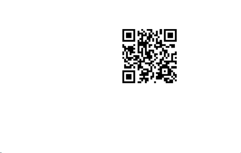
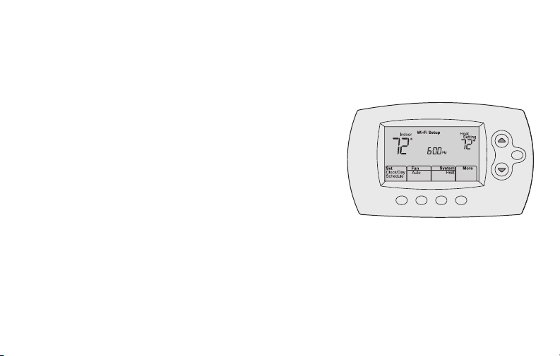
Controls and home screen quick reference
Once your Wi-Fi thermostat is installed, it will display the home screen. Portions of this
display will change depending on how you are viewing it.
Set up messages
describe steps in the
Wi-Fi set up process
Set clock, day,
or schedule
Select fan
settings
HOLD
Select system
mode
Wi-Fi status
Temperature adjustment
buttons
Permanent override
button
Additional
settings
The screen lights when you press any button. It stays lit for 8 seconds after you complete
changes.
5 69-2718EF—03
Page 8
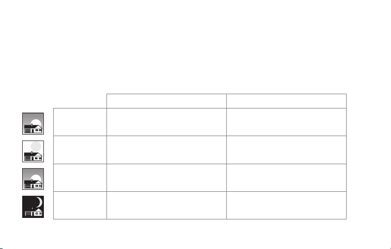
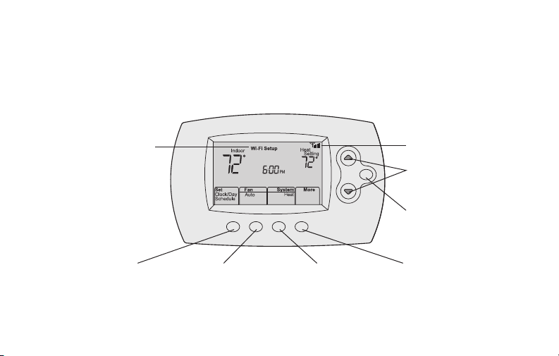
Preset energy-saving schedules
This thermostat is pre-set with energy-saving program settings for four time periods.
Using the default settings can reduce your heating/cooling expenses if used as directed.
Savings may vary depending on geographic region and usage. To change the settings,
see pages 39–41.
Default Heat Settings Default Cool Settings
WAKE
6:00 am
LEAVE
8:00 am
RETURN
6:00 pm
SLEEP
10:00 pm
69-2718EF—03 6
70
62
70
62
°
°
°
°
78
85
78
82
°
°
°
°
Page 9

Setting up your thermostat
Setting up your Wi-Fi programmable thermostat is easy. It is preprogrammed and ready to
go as soon as it is installed and registered.
Install your thermostat.
1
Connect your home Wi-Fi network.
2
Register online for remote access.
3
Before you begin, you may want to watch a brief installation video. Use
the QR Code® at the front of this guide, or go to wifithermostat.com/support
7 69-2718EF—03
Page 10
Installing your thermostat
You might need the following tools to install this thermostat:
• No. 2 Phillips screwdriver
• Small pocket screwdriver
• Pencil
• Level (optional)
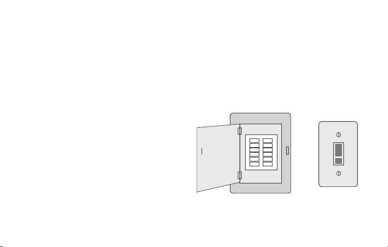
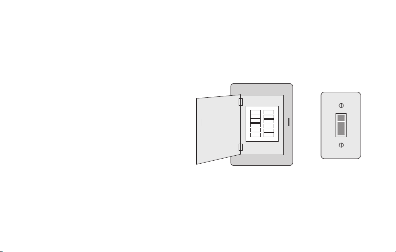
1 Switch OFF power to your
heating/cooling system.
Important! To protect your equipment,
switch OFF the power to your heating/
cooling system at the breaker box or
the system switch.
69-2718EF—03 8
• Drill and bits (3/16” for drywall,
7/32” for plaster) (optional)
• Hammer (optional)
• Electrical tape (optional)
Circuit breaker
box
or
Heating/cooling
system power
switch
Page 11
Installing your thermostat
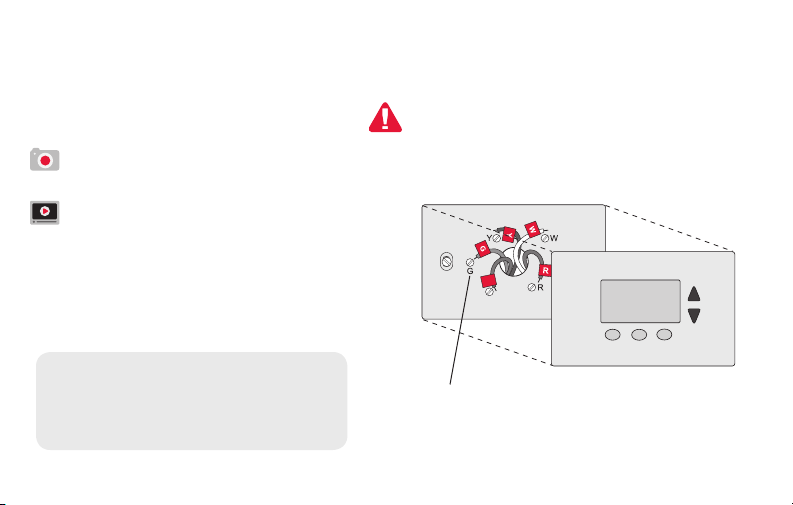
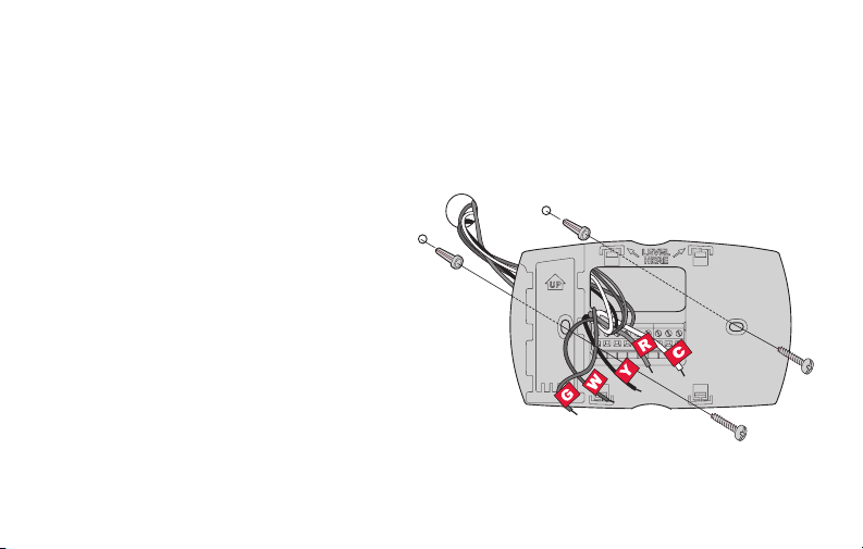
2 Remove old thermostat faceplate
and leave wires connected.
2a Take a picture of the wire
If you have an older thermostat with a
sealed mercury tube, turn to page 2
for proper disposal instructions.
connections for later reference.
2b If no wire is connected to a terminal
labeled C or no C terminal exists
on the old thermostat, view the
Alternate Wiring videos at
wifithermostat.com/videos
C
C
Important! C wire is required and
is the primary power source for
your thermostat. Without a C wire,
your thermostat will not power up.
9 69-2718EF—03
Terminal
designation
Page 12
Installing your thermostat
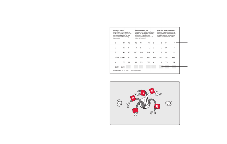
3 Label wires.
Do not label by wire color.Use
the supplied sticky tags to label
each wire as you disconnect it.
Label wires according to the old
thermostat terminal designations,
not by wire color.
Note: If no tag matches a wire
terminal label, write the terminal
label on a blank tag.
4 Remove wallplate.
Remove the old wallplate from
the wall after all wires have been
labeled and disconnected.
69-2718EF—03 10
Sticky tags
Blank sticky
tags
C
C
Terminal
designation
Page 13
Installing your thermostat
M33856
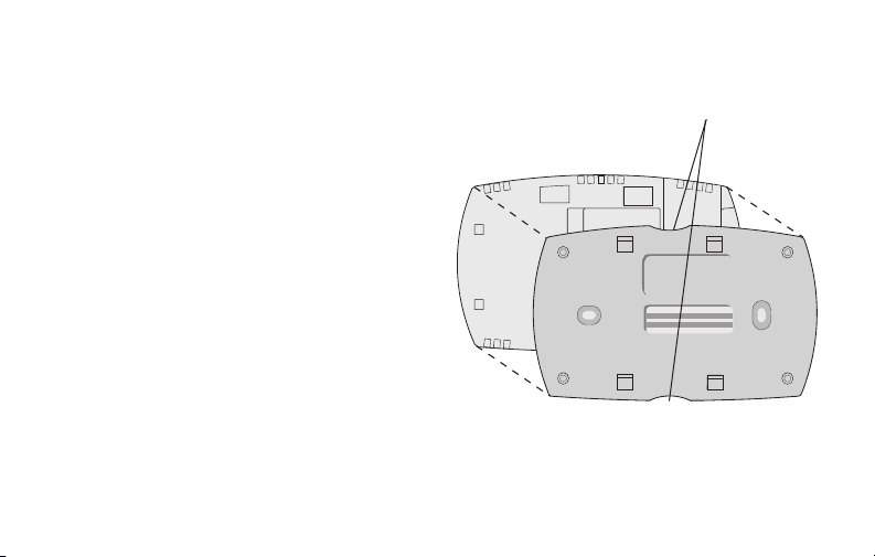
5 Separate Wi-Fi thermostat and its
wallplate.
On your new thermostat, grasp the
Thermostat
Finger holds
finger holds on the top and bottom of
the wallplate with one hand and the
thermostat (front) with the other hand.
PULL HERE
TO REMOVE
Pull pieces apart.
PULL HERE
TO REMOVE
Wallplate (back view)
11 69-2718EF—03
Page 14
Installing your thermostat
MCR33857
6 Mount wallplate for Wi-Fi thermostat.
Mount your new wallplate using screws and anchors
included with the thermostat.
If necessary:
Drill 3/16-in holes for drywall.
Drill 7/32-in holes for plaster.
Note: You may be able to use your existing
wall anchors. Hold the wallplate up to the
existing anchors to check for alignment
Wallplate
69-2718EF—03 12
Page 15

Installing your thermostat
Important! The Wi-Fi thermostat requires a C wire to operate. The C, or common, wire
brings 24 VAC power to the thermostat. Many older mechanical or battery operated
thermostats do not require a C wire. If you don’t have a C wire, try:
• Looking for an unused wire that is pushed into the wall. Connect that wire to C and
check that it is connected to the 24 VAC common at your heating/cooling system.
Note: Not all heating/cooling systems label the 24 VAC common C. Check your system
manual or contact the manufacturer to find out which terminal is the 24 VAC common.
View the Alternate Wiring videos at wifithermostat.com/videos
Wiring
For conventional heating/cooling systems (natural gas, oil or electric furnace, air
conditioner), see page 14. See “Glossary” on page 64 for further definition.
For a heat pump system, see page 15. See “Glossary” on page 64 for further
definition.
13 69-2718EF—03
Page 16
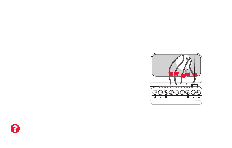
Installing your thermostat
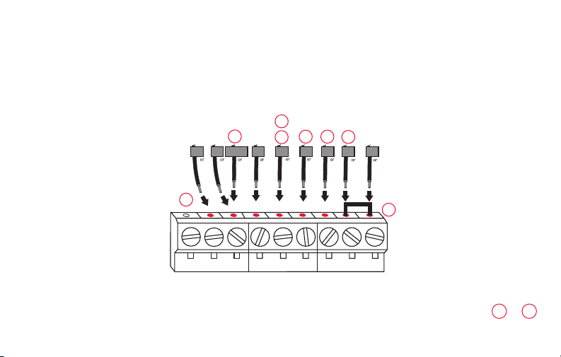
Wiring (conventional system)
7A Wire the Wi-Fi thermostat to your conventional system.
a Starting with the C Wire, match the sticky tag on the
wire to the terminal labels.
You must have a C wire. See page 13.
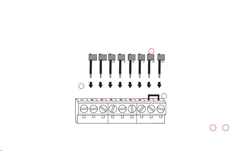
b Loosen screw, insert wire on inside edge
of terminal, then tighten screw.
c Verify wire is firmly secured by gently
pulling on wire.
d Repeat steps a–c for all other wires.
e Push any excess wire back into the wall
opening after all wires are installed.
f Continue to page 20.
Labels don’t match? See alternate
wiring key on pages 16–17.
69-2718EF—03 14
Remove metal jumper
only if you have both
R and RC wires
W
G
Y
R
C
C
G W
Y2
W2
AUX/E
L
G O/B
YR RCK
CONVENTIONAL
C
YRRCK
HEAT PUMP
Note: The wiring for your
application might be different
from the shown above.
Page 17
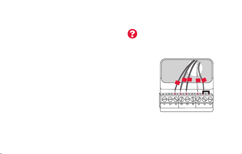
Installing your thermostat
Wiring (heat pump system only)
7B Wire Wi-Fi thermostat to your heat pump.
Labels don’t match? See alternate
wiring key on pages 18–19.
a Starting with the C Wire, match the sticky tag on the wire to the terminal labels.
You must have a C wire. See page 13.
b Loosen screw, insert wire on inside edge
of terminal, then tighten screw.
c Verify wire is firmly secured by gently
pulling on wire.
O
G
Aux
R
Y
d Repeat steps a–c for all other wires.
e Push any excess wire back into the wall
opening after all wires are installed
f
Continue to page 20.
Note: If old thermostat has separate wires on AUX and
E, place both wires into the E/AUX terminal.
If old thermostat has wire on AUX with a jumper to E,
place wire on E/AUX terminal. No jumper is required.
15 69-2718EF—03
.
AUX/E
L
G O/B
C
YRRCK
HEAT PUMP
Note: The wiring for your
application might be different
from the wiring shown above.
Page 18
Installing your thermostat
MCR33885
CONVENTIONAL
Alternate wiring (conventional system)
Use this if your wire labels don’t match the terminal labels.
Y2
Note: You must have
W2
a C wire or equivalent.
See page 13.
1
W2
G W
Y2
K
69-2718EF—03 16
W1F
H
C
X
B
C1
C
YRRC
2
RYWG
RC
R
RHY1
4M
V
3
See key to 1 – 3
on page 17.
Page 19

Installing your thermostat
Alternate wiring key (conventional system)
1
Do not use K terminal. For future use.
If your old thermostat had both R and RH wires, remove metal jumper.
2
Connect the R wire to the RC terminal, and the RH wire to the R terminal.
Remove metal jumper connecting R and RC only if you must connect both
3
R and RC.
17 69-2718EF—03
Page 20
Installing your thermostat
MCR33886
T PUMP
Alternate wiring (heat pump system only)
Use this if your wire labels don’t match the terminal labels.
3
Note: You must have
a C wire or equivalent.
See page 13.
EAUX
L
XW FH
F
X2
1
2
4
OG
W1
W2
5
4
C
X
B
B
6
RY
RC
R
VY1
VRM
7
AUX/E
G O/B
L
69-2718EF—03 18
C
YRRCK
HEA
See key to 1 – 7
on page 19.
Page 21

Installing your thermostat
Alternate wiring key (heat pump system only)
Do not use K terminal. For future use.
1
If old thermostat has separate wires on AUX and E, place both wires into the E/AUX terminal. If
2
old thermostat has wire on AUX with a jumper to E, place wire on E/AUX terminal. No jumper is
required.
If your old thermostat had an O wire and not a B wire, attach the O wire to the O/B terminal.
3
If your old thermostat had separate O and B wires, attach the B wire to the C terminal. If
4
another wire is attached to the C terminal, check wifithermostat.com for help. Attach the O wire
to the O/B terminal.
If your old thermostat had separate Y1, W1 and W2 wires, check wifithermostat.com for help.
5
If your old thermostat had both V and VR wires, check wifithermostat.com for help.
6
Leave metal jumper between R and RC terminals in place.
7
19 69-2718EF—03
Page 22
Installing your thermostat
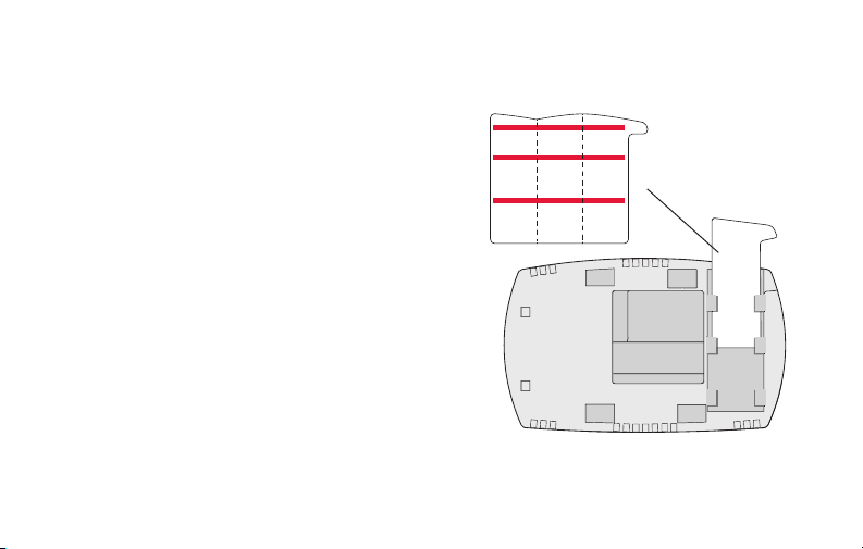
8 Insert quick reference card.
Fold quick reference card
along score lines, and slide
it into the slot on the back of
the thermostat.
69-2718EF—03 20
Quick
reference
card
MCR33916
Back of thermostat
Page 23
Installing your thermostat
M33860
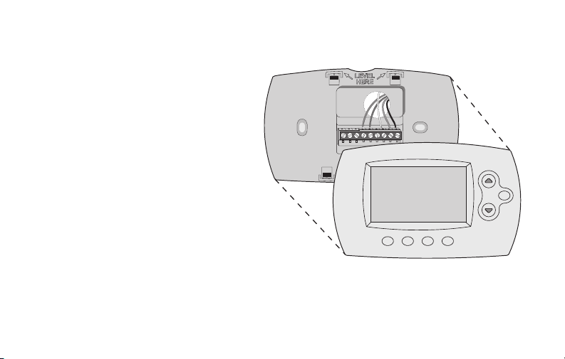
9 Attach thermostat to wallplate.
Align the thermostat to the wallplate
and then snap into place.
HOLD
21 69-2718EF—03
Page 24
Installing your thermostat
10 Switch heating/cooling system ON.
Important!
10a Verify that the C wire is
connected at the thermostat
and at the heating/cooling
system.
10b Make sure the heating/
cooling system door is firmly
secured.
10c Switch power back ON for
your heating/cooling system
at the breaker box or its
power switch.
69-2718EF—03 22
Circuit breaker
box
or
Heating/cooling
system power
switch
Page 25
Installing your thermostat
MCR33909
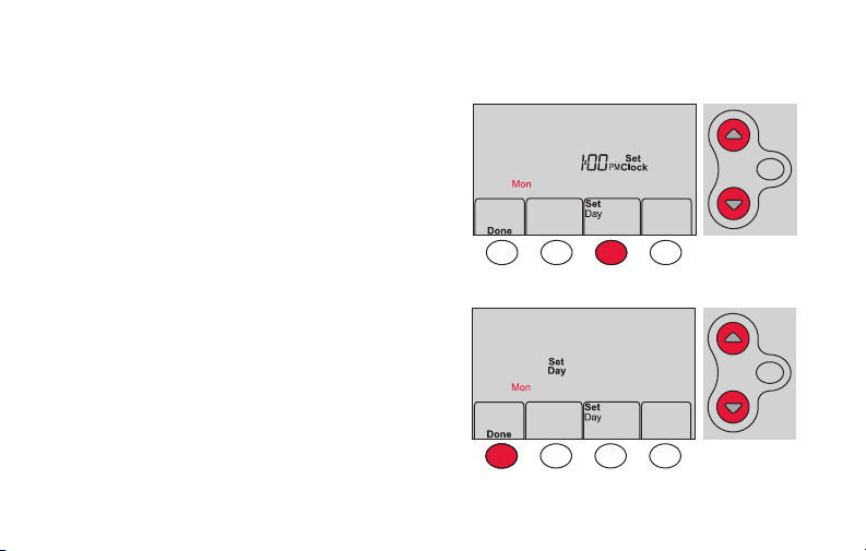
11 Set clock to current day and time.
11a Press s or t to set clock.
11b Press Set Day.
11c Press s or t to select the
day of week.
11d Press Done to save.
(Press and hold a st button to
quickly change a setting.)
HOLD
MCR33908
HOLD
23 69-2718EF—03
Page 26
Installing your thermostat
12 Determine your heating/cooling system type.
Important! Heating/cooling system type must be set so that your
thermostat operates properly and does not damage your system.
12a If your system type is conventional single stage (natural gas-powered single
stage with a/c), continue to “Connecting to your Wi-Fi network” on page 26.
12b If your system is:
• Conventional multistage heat and cool
• Any type of heat pump
• Hydronic
• Other
You MUST change the system type by setting system function 1. See page 48
to match your thermostat to your system type.
69-2718EF—03 24
If you are not sure of your
heating/cooling system type
or have other questions, go
to wifithermostat.com/support
Page 27
Installing your thermostat
MCR33880
Congratulations! Your thermostat is operational.
13 Test your thermostat
13a Press the
heating or cooling and begin operation.
13b For remote access to your thermostat,
continue to
network” on page 26.
25 69-2718EF—03
System
button to change to
“Connecting to your Wi-Fi
Heating/cooling system not turning
on? Refer to page 62 or FAQ at
wifithermostat.com/support
Page 28

Connecting to your Wi-Fi network
To complete this process, you must have a wireless device connected to your home
wireless network. Any of these device types will work:
• Tablet (recommended)
• Laptop (recommended)
• Smartphone
If you get stuck... at any point in this procedure, restart the thermostat by
removing the thermostat from the wallplate, wait for 10 seconds, and snap it back
onto the wallplate. Go to Step 1 in this procedure, starting on page 27.
View the Wi-Fi Enrollment video at wifithermostat.com/videos
69-2718EF—03 26
Page 29
Connecting to your Wi-Fi network
M33852
1 Connect to your thermostat.
1a Make sure the thermostat displays
Wi-Fi Setup.
1b On the wireless device (laptop, tablet,
smartphone), view the list of available Wi-Fi
networks.
1c Connect to the network called
NewThermostat_123456 (the number will
vary).
Note: If you are asked to specify a home, public, or
office network, select Home Network.
27 69-2718EF—03
HOLD
Page 30

Connecting to your Wi-Fi network
M31567
2 Join your home network.
2a Open your web browser to access the
Thermostat Wi-Fi Setup page. The browser
should automatically direct you to the correct
page; if it does not, go to http://192.168.1.1
2b Find the name of your home network on this
page and select it.
Note: Some routers have enhanced features such as
guest networks; use your home network.
2c Complete the instructions for joining your Wi-Fi
network and click on the Connect button.
(Depending on your network setup, you may see
an instruction such as Enter Password for your home network.)
Note: If you did not correctly connect to the thermostat, you may see
your home router page. If so, return to Step 1.
69-2718EF—03 28
Page 31

Connecting to your Wi-Fi network
Note: If your Wi-Fi network does not appear in the list on the Thermostat Wi-Fi Setup
page:
• Try performing a network rescan by pressing the Rescan button. This is helpful in
areas with a lot of networks.
• If you are connecting to a hidden network, then enter the network SSID in the
textbox, select the encryption type from the drop down menu, and click on the
Add button. This manually adds the network to the top of the list. Click on the new
network in the list and enter the password if necessary. Click on Connect to join the
network.
29 69-2718EF—03
Page 32

Connecting to your Wi-Fi network
3 Make sure your thermostat is connected.
While the connection is in process, your thermostat
will flash Wait for up to 3 minutes. When the
connection is complete, the display will show Wi-Fi
Setup Connection Success. The Wi-Fi signal strength will
appear in the top-right corner.
After about 60 seconds, the home screen will appear
and Register at Total Connect will flash until registration
is complete.
If you don’t see these messages, see page 26.
To register online for remote access to your thermostat
continue on page 31.
Note: If the thermostat displays Connection Failure or continues to display
Wi-Fi Setup, confirm you correctly entered your home network password in
step 2. If correct, refer to the FAQ at wifithermostat.com/support
69-2718EF—03 30
Page 33

Registering your thermostat online
To view and set your Wi-Fi thermostat
remotely, you must have a Total Connect
Comfort account. Use the following steps.
1 Open the Total Connect Comfort web site.
Go to mytotalconnectcomfort.com
View the Wi-Fi Thermostat Registration
video at wifithermostat.com/videos
M31570
31 69-2718EF—03
Page 34

Registering your thermostat online
2 Login or create an account.
If you have an account,
click Login
– or –
click Create An Account
2a Follow the instructions on the screen.
2b Check your email for an activation
message from My Total Connect
Comfort. This may take several minutes.
Note: If you do not receive a response, check
your junk mailbox or use an alternate e-mail
address.
2c Follow activation instructions in the
email.
2d Log in.
69-2718EF—03 32
.
M31571
Page 35

Registering your thermostat online
Printed in U.S.A.
69-2723EFS-01
3 Register your Wi-Fi thermostat.
After you are logged in to your Total Connect Comfort account,
register your thermostat.
3a Follow the instructions on the
screen. After adding your
thermostat location, you must enter
the thermostat’s unique identifiers:
• MAC ID
• MAC CRC
Note: These IDs are listed on the
Thermostat ID Card included in the
thermostat package. The IDs are not
case sensitive.
33 69-2718EF—03
Thermostat ID Card
Use the MAC ID and CRC ID to register
this product at mytotalconnectcomfort.com
Carte d’identification de thermostat
Utilisez l’identication MAC et l’identication CRC pour
enregistrer ce produit à mytotalconnectcomfort.com
Tarjeta de identificación del termostato
Utilice la identicación MAC y la identicación CRC para
inscribir este producto en mytotalconnectcomfort.com
® U.S. Registered Trademark.
© 2012 Honeywell International Inc.
69-2723EFS—01 M.S. 04-12
MAC ID MAC CRC
HONEYWELL MODEL:
MAC ID: MAC CRC:
Page 36

Registering your thermostat online
3b When the thermostat is
successfully registered,
the Total Connect Comfort
registration screen will
display a SUCCESS
message.
In the thermostat display, you
will see Setup Complete for
about 90 seconds.
69-2718EF—03 34
Page 37

Registering your thermostat online
iTunes
3c Also notice that your thermostat displays
its signal strength.
Congratulations! You’re done.
You can now control your thermostat from
anywhere through your tablet, laptop, or
smartphone
Total Connect Comfort free app is
available for Apple® iPhone®, iPad® and
iPod touch® devices at iTunes® or at
Google Play® for all Android™ devices.
GET IT ON
35 69-2718EF—03
Download on
Page 38

Setting the time and day
MCR33855
1 Press Set Clock/Day/Schedule, then press s
or t to set clock.
2 Press Set Day, then press s or t to select
the day of week.
3 Press Done to save.
Note: If the Set Clock/Day/Schedule option is not
displayed, press Done.
Note: If the display flashes Set Clock, the
thermostat will follow your settings for the
Monday “Wake” time period until you reset the
time and day.
69-2718EF—03 36
HOLD
HOLD
Page 39

Setting the fan
MCR33895
Press Fan to select On or Auto (toggle to
re-select).
Auto
: Fan runs only when the heating or
cooling system is on. Auto is the most
commonly used setting.
On: Fan is always on.
Note: Options may vary depending on your
heating/cooling equipment.
37 69-2718EF—03
Page 40

Selecting system mode
MCR33880
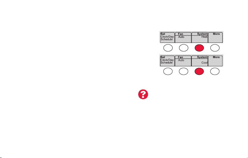
Press System to select:
Heat: Controls only the heating system.
Cool: Controls only the cooling system.
Off: Heating/cooling systems are off.
Auto: Selects heating or cooling depending on
the indoor temperature.
Em Heat (heat pumps with aux. heat):
Controls auxiliary/emergency heat.
Compressor is off.
69-2718EF—03 38
Note: Depending on how
your thermostat was installed,
you may not see all system
settings.
Page 41

Adjusting program schedules
MCR33892
1 Press Set Clock/Day/Schedule, then Set Schedule.
2 Press s or t to set your Monday (Mon) Wake
time, then press Next.
3 Press s or t to set the temperature for this
period, then press Next.
4 Set time and temperature for the next time
period (Leave). Repeat Steps 2 and 3 for each
time period.
5 Press Next to set time periods for the next day.
Repeat Steps 2 through 4 for each day.
6 Press Done to save and exit.
Note: Make sure the thermostat is set to the
system mode you want to program (Heat or Cool).
39 69-2718EF—03
Page 42

Overriding schedules temporarily
MCR33896
Press s or t to immediately adjust the
temperature.
The new temperature will be maintained only
until the next programmed time period begins.
To cancel the temporary setting at any time,
press Cancel. The program schedule will
resume.
69-2718EF—03 40
HOLD
Page 43

Overriding schedules permanently
1 Press HOLD to permanently adjust the
temperature. This will turn off the program
schedule.
2 Press s or t to adjust the temperature
setting. The temperature you set will
be maintained 24 hours a day until you
manually change it or press Cancel to
resume the program schedule
41 69-2718EF—03
HOLD
MCR33897
Page 44

Unregistering thermostat
M33876
If you remove the thermostat from your
Total Connect Comfort website account
(for example, you’re moving and leaving
the thermostat behind), the thermostat will
display Register at Total Connect until it is
re-registered.
69-2718EF—03 42
Page 45

Disconnecting Wi-Fi
M33855
Replacing your router
If you disconnect the thermostat from your Wi-Fi
network:
1 Enter system setup (see page 48).
2 Change setting 39 to 0 (see page 54).
The screen will display Wi-Fi Setup.
Re-connect to a Wi-Fi network by following the steps on page 26.
Turning Wi-Fi off
If you do not plan to control the thermostat remotely, you can remove the Wi-Fi Setup
message from the screen:
1 Enter system setup (see page 48).
2 Change setting 38 to 0 (see page 54). Wi-Fi Setup will be removed from the screen.
If you want to connect to the Wi-Fi network later, change setting 38 back to 1.
43 69-2718EF—03
Page 46

Software updates
Honeywell periodically issues updates to the software for
this thermostat. The updates occur automatically through
your Wi-Fi connection. All your settings are saved, so
you will not need to make any changes after the update
occurs.
While the update is taking place, your thermostat screen
flashes Updating and shows the percentage of the update
that has occurred. When the update is complete, your
home screen will appear as usual.
Note: If you are not connected to Wi-Fi, you will not get
automatic updates.
69-2718EF—03 44
Percentage of
update complete
Page 47

M33881
Smart Response Technology
This feature allows the thermostat to “learn”
how long the heating/cooling system takes to
reach programmed temperature settings, so
the temperature is reached at the time you set.
For example: Set the Wake time to 6:00 am,
and the temperature to 70°. The heat will come
on before 6:00 am, so the temperature is 70°
by 6:00 am.
Note: System setting function 13 controls
Smart Response Technology. See “Smart
Response Technology” on page 52.
45 69-2718EF—03
The message Recovery
is displayed when the
system is activated before
a scheduled time period.
Page 48

Compressor protection
M33882
This feature forces the compressor to wait
a few minutes before restarting, to prevent
equipment damage.
69-2718EF—03 46
The message Cool On (or
Heat On for a heat pump)
will flash during the wait
time.
Page 49

Auto changeover
This feature is used in climates where both
air conditioning and heating are used on the
same day.
When the system is set to Auto,
the thermostat automatically
selects heating or cooling
depending on the indoor temperature.
Heat and cool settings must be at least
3 degrees apart. The thermostat will
automatically adjust settings to maintain this
3-degree separation.
Note: System setting function 12 controls
Auto changeover. See “Manual/Auto
Changeover” on page 51.
47 69-2718EF—03
MCR33893
Page 50

Setting functions and options
You can change options for a number of system functions. Available functions depend on
the type of system you have. The functions, along with available options are described on
pages 50–54.
This thermostat is pre-set for a single-stage heating/cooling system.
Setting function 1 for a heat pump will adjust the default settings.
69-2718EF—03 48
Page 51

Setting functions and options
MCR33884
1 Press Fan and s simultaneously and hold
for approximately 3 seconds. The screen
will change to display two numbers and
the button designations will be Done, Back,
blank, Next.
2 Press Next until you see the function
number—the larger number on the left—
you want to set.
3 Change options for any function by
pressing s or t until the correct option
(smaller number on right) is displayed.
4 Repeat Steps 2 and 3 until you have set all
functions that you wish to change.
5 When you have made all changes, press
Done to save and exit.
49 69-2718EF—03
HOLD
MCR33883
HOLD
Page 52

System setup
(See page 48 for instructions.)
Function Settings & Options
Select System
1
Type
If you are not sure
of your heating/
cooling system
type or have other
questions, go to
withermostat.com
Heat Pump
2
Changeover Valve
(for heat pumps
only)
69-2718EF—03 50
0 Heat/cool: Gas, oil or electric heating with central air conditioning.
1 Heat pump: Heat pump without backup or auxiliary heat.
2 Heat only: Gas, oil or hot water heat without central air conditioning.
3 Heat only with fan: Gas, oil or electric heat without central air
conditioning.
4 Cool only: Central air conditioning only.
5 Heat pump: Heat pump with backup or auxiliary heating.
6 Heat/Cool Multiple stages: 2 heat stages (wires on W and W2), 2
cooling stages (wires on Y and Y2).
7 Heat/Cool Multiple stages: 2 heat stages (wires on W and W2), 1
cooling stage (wire on Y).
8 Heat/Cool Multiple stages: 1 heat stage (wires on W), 2 cooling stages
(wire on Y and Y2).
0 Cooling changeover valve: Use this setting if you connected a wire
labeled “O” to the O/B terminal.
1 Heating changeover valve: Use this setting if you connected a wire
labeled “B” to the O/B terminal.
Page 53

System setup
(See page 48 for instructions.)
Function Settings & Options
Heating Fan
3
Control
Heating Cycle
5
Rate
Heating Cycle
6
Rate Stage 2
Manual/Auto
12
Changeover
See page 47 for
more information.
51 69-2718EF—03
0 Gas or oil heat: Use this setting if you have a gas or oil heating system
(system controls fan operation).
1 Electric heat: Use this setting if you have an electric heating system
(thermostat controls fan operation).
5 Gas or oil furnace: Standard gas/oil furnace (less than 90% efficiency).
9 Electric furnace: Electric heating systems.
3 Hot water or high-efficiency furnace: Hot water system or gas furnace
(more than 90% efficiency).
1 Gas/oil steam or gravity system: Steam or gravity heat systems.
0 Manual changeover (Heat/Cool/Off).
1 Automatic changeover (Heat/Cool/Auto/Off). Automatically turns on Heat
or Cool based on room temperature. Note: System maintains minimum
3°F difference between heat and cool settings.
Page 54

System setup
(See page 48 for instructions.)
Function Settings & Options
Smart Response
13
Technology
See page 45 for
more information.
Temperature For-
14
mat (°F/°C)
Schedule Options
16
69-2718EF—03 52
1 On
0 Off
0 Fahrenheit
1 Celsius
1 Program schedule is on (7-day programmable).
0 Program schedule is off. Thermostat can not be programmed.
Page 55

System setup
(See page 48 for instructions.)
Function Settings & Options
Device Name
36
This name will
identify the
thermostat when
you view it remotely.
If you register
multiple thermostats,
give each one a
different name.
53 69-2718EF—03
52 = Thermostat
1 Basement 16 Exercise Room 30 Library 44 Porch
2 Bathroom 17 Family Room 31 Living Room 45 Rec Room
3 Bathroom 1 18 Fireplace 32 Lower Level 46 Sewing Room
4 Bathroom 2 19 Foyer 33 Master Bath 47 Spa
5 Bathroom 3 20 Game Room 34 Master Bed 48 Storage Room
6 Bedroom 21 Garage 35 Media Room 49 Studio
7 Bedroom 1 22 Great Room 36 Music Room 50 Sun Room
8 Bedroom 2 23 Guest Room 37 Nursery 51 Theater
9 Bedroom 3 24 Gym 38 Office 52 Thermostat
10 Bedroom 4 25 Kid's Room 39 Office 1 53 Upper Level
11 Boat House 26 Kitchen 40 Office 2 54 Utility Room
12 Bonus Room 27 Kitchen 1 41 Pantry 55 Walk In Closet
13 Computer Room 28 Kitchen 2 42 Play Room 56 Wine Cellar
14 Den 29 Laundry Room 43 Pool Room 57 Workshop
15 Dining Room
Page 56

System setup
(See page 48 for instructions.)
Function Settings & Options
Wi-Fi On/Off
38
Wi-Fi Connection
39
Show period and
42
day of week
Restore Schedule
85
Defaults
Restore Original
90
Settings
69-2718EF—03 54
1 Wi-Fi is on and can be connected to a Wi-Fi network.
0 Wi-Fi is off. Thermostat cannot be connected to a Wi-Fi network. If you
are not connecting the thermostat to a Wi-Fi network this will remove the
text Wi-Fi Setup from the messaging center.
1 Connected to Wi-Fi network. This is set automatically when the
thermostat is connected to the Wi-Fi network.
0 Set to 0 to disconnect from the Wi-Fi network.
0 Period and day are not shown on the home screen.
1 Period and day are shown on the home screen.
0 Continue using programmed schedule.
1 Restore thermostat program to energy saving settings
0 No
1 Disconnects thermostat from Wi-Fi and restores original settings (erases
customizations).
Page 57

Frequently asked questions
:Q Will my thermostat still work if I lose my Wi-Fi connection?
:A Yes, the thermostat will operate your heating and/or cooling system with or without Wi-Fi.
:Q How do I find the password to my router?
:A Contact the manufacturer of the router or check the router documentation.
:Q Why am I not seeing my Wi-Fi setup page?
:A You are probably connected only to your router, not to your thermostat. Try connecting to the
thermostat again.
:Q Why isn’t my thermostat connecting to my Wi-Fi router even though it is very close to the
thermostat?
:A Verify that the password entered for the Wi-Fi router is correct.
55 69-2718EF—03
Page 58

Frequently asked questions
:Q Where can I find my MAC ID and MAC CRC codes?
:A The MAC ID and MAC CRC numbers are included on a card packed with the thermostat or on the
back of the thermostat (visible when removed from wallplate). Each thermostat has a unique MAC
ID and MAC CRC.
:Q My thermostat is unable to register to the Total Connect Comfort website.
:A Verify that the thermostat is correctly enrolled on your home Wi-Fi network. The message center
will display Wi-Fi Setup or Register at Total Connect. You might also see the Wi-Fi Signal strength
icon. Verify that the Wi-Fi router has a good internet connection. On your computer, verify that
you can open the site at mytotalconnectcomfort.com
If you cannot open the site, switch off the internet modem for a few seconds, then power it
back on.
69-2718EF—03 56
Page 59

Frequently asked questions
:Q I registered on the Total Connect Comfort website but was unable to login using my new
account.
:A Check your email and ensure that you received an activation email. Follow the instructions to
activate your account and then login to the website.
:Q I have signed up on the Total Connect Comfort website and have not received a
confirmation email.
:A Check for the email in your Junk or Deleted folder.
:Q Is there a way to extend the signal strength?
:A Most standard routers can be set up to be a repeater. You can also purchase and install a Wi-Fi
repeater.
For more FAQs, see wifithermostat.com/support
57 69-2718EF—03
Page 60

Troubleshooting
Lost Signal
If the no-Wi-Fi indicator displays in place of the
Wi-Fi strength indicator in the upper right hand
corner of the home screen:
• Check another device to be sure Wi-Fi is
working in your home; if not, call your Internet
Service Provider.
• Move the router.
• Restart the thermostat: remove it from the
wallplate, wait 10 seconds, and snap it
back onto the wallplate. Return to Step 1 of
Connecting to your Wi-Fi network.
69-2718EF—03 58
M33997M33997
Page 61

Troubleshooting
Error Codes
For certain problems, the thermostat screen will display
a code that identifies the trouble. Initially, error codes are
displayed alone in the time area of the screen; after a
few minutes, the home screen is displayed and the code
alternates with the time.
Error Code Action
During Wi-Fi Setup, the router
E01
lost power.
• Ensure your router has power.
• If trying to connect to a hidden or manually added network,
confirm the router has power and is working.
Invalid Wi-Fi password. This
E02
code displays for 30 seconds,
then the thermostat will re-enter
Wi-Fi Setup mode.
59 69-2718EF—03
• Re-enter password for your home Wi-Fi network.
• Repeat setup process and confirm your password for your home
Wi-Fi network.
Page 62

Troubleshooting
Error Code Action
Router is not issuing
E42
an IP address to the
thermostat.
No internet connection.
E43
Thermostat cannot
communicate to Total
Connect Comfort.
General error Remove thermostat from wallplate for
E99
69-2718EF—03 60
• Wait for 30 minutes, connection can take
several minutes.
• If still no connection, remove thermostat
from wallplate for 10 seconds, then
reconnect it (see page 26).
• Verify your router is correctly setup to
automatically give IP addresses.
• Make sure the Internet cable is plugged
in.
• Reboot the router.
10 seconds, then reconnect it (
26).
see page
Page 63

Troubleshooting
If you have difficulty with your thermostat, please try the following suggestions.
Most problems can be corrected quickly and easily.
Display is
blank
• Check circuit breaker and reset if necessary.
• Make sure power switch at heating and cooling system is on.
• Make sure furnace door is closed securely.
• Make sure C wire is connected (see page 13).
Cannot change
system setting
to Cool
Fan does
not turn on
when heat is
required
Cool On or Heat
On is flashing
on the screen
61 69-2718EF—03
• Check Function 1: System Type to make sure it is set to match your heating
and cooling equipment (see page 50).
• Check Function 3: Heating Fan Control to make sure it is set to match your
heating equipment (see page 51).
• Compressor protection feature is engaged. Wait 5 minutes for the system to
restart safely, without damage to the compressor.
Page 64

Troubleshooting
Heat pump
issues cool air
in heat mode,
or warm air in
cool mode
Heating or
cooling system
does not
respond
69-2718EF—03 62
• Check Function 2: Heat Pump Changeover Valve to make sure it is properly
configured for your system (see page 50).
• Press System to set system to Heat. Make sure the temperature is set higher
than the Inside temperature.
• Press System to set system to Cool. Make sure the temperature is set lower
than the Inside temperature.
• Check circuit breaker and reset if necessary.
• Make sure power switch at heating & cooling system is on.
• Make sure furnace door is closed securely.
• Wait 5 minutes for the system to respond.
Page 65

Troubleshooting
Heating system
is running in
cool mode
Heating
and cooling
equipment are
running at the
same time
63 69-2718EF—03
• Check Function 1: System Type to make sure it is set to match your heating
and cooling equipment (see page 50).
• Check Function 1: System Type to make sure it is set to match your heating
and cooling equipment (see page 50).
• Grasp and pull thermostat away from wallplate. Check to make sure bare
wires are not touching each other.
• Check thermostat wiring is correct.
Page 66

Glossary
C wire
The “C” or common wire brings 24 VAC power to the thermostat from the heating/cooling system.
Some older mechanical or battery operated thermostats may not have this wire connection. It is
necessary for establishing a Wi-Fi connection to your home network.
Heat Pump heating/cooling system
Heat pumps are used to heat and cool a home. If your old thermostat has a setting for auxiliary or
emergency heat, you likely have a heat pump.
Conventional heating/cooling system
Non–heat pump type systems; these include air handlers, furnaces or boilers that run on natural gas,
oil or electricity. They may or may not include an air conditioner.
Jumper
A small piece of wire that connects two terminals together.
MAC ID, MAC CRC
Alphanumeric codes that uniquely identify your thermostat.
QR Code
Quick response code. A two-dimensional,machine-readable image. Your wireless device can read
the black and white pattern in the square and link its browser directly to a web site. QR Code is a
registered trademark of DENSO WAVE INCORPORATED.
69-2718EF—03 64
®
Page 67

Regulatory information
FCC Compliance Statement (Part 15.19) (USA only)
This device complies with Part 15 of the FCC Rules.
Operation is subject to the following two conditions:
1 This device may not cause harmful interference, and
2 This device must accept any interference received,
including interference that may cause undesired
operation.
FCC Warning (Part 15.21) (USA only)
Changes or modifications not expressly approved by the
party responsible for compliance could void the user’s
authority to operate the equipment.
FCC Interference Statement (Part 15.105 (b))
(USA only)
This equipment has been tested and found to comply
with the limits for a Class B digital device, pursuant to
Part 15 of the FCC Rules. These limits are designed
to provide reasonable protection against harmful
interference in a residential installation. This equipment
generates uses and can radiate radio frequency energy
and, if not installed and used in accordance with the
instructions, may cause harmful interference to radio
communications. However, there is no guarantee that
interference will not occur in a particular installation. If
this equipment does cause harmful interference to radio
or television reception, which can be determined by
turning the equipment off and on, the user is encouraged
to try to correct the interference by one of the following
measures:
• Reorient or relocate the receiving antenna.
• Increase the separation between the equipment and
receiver.
• Connect the equipment into an outlet on a circuit
different from that to which the receiver is connected.
• Consult the dealer or an experienced radio/TV
technician for help.
65 69-2718EF—03
Page 68

Regulatory information
Thermostats
To comply with FCC and Industry Canada RF exposure
limits for general population/ uncontrolled exposure, the
antenna(s) used for these transmitters must be installed
to provide a separation distance of at least 20 cm from
all persons and must not be co-located or operating in
conjunction with any other antenna or transmitter.
RSS-GEN
Under Industry Canada regulations, this radio transmitter
may only operate using an antenna of type and
maximum (or lesser) gain approved for the transmitter by
Industry Canada. To reduce potential radio interference
to other users, the antenna type and its gain should
be so chosen that the equivalent isotropically radiated
power (e.i.r.p.) is not more than that necessary for
successful communication.
69-2718EF—03 66
Operation is subject to the following two conditions:
1 this device may not cause interference, and
2 this device must accept any interference, including
interference that may cause undesired operation of the
device.
Page 69

1-year limited warranty
Honeywell warrants this product, excluding battery, to be free from defects in the workmanship or materials, under normal use and
service, for a period of one (1) year from the date of purchase by the consumer. If at any time during the warranty period the product is
determined to be defective or malfunctions, Honeywell shall repair or replace it (at Honeywell’s option).
If the product is defective,
(i) return it, with a bill of sale or other dated proof of purchase, to the place from which you purchased it; or
(ii) call Honeywell Customer Care at 1-855-733-5465. Customer Care will make the determination whether the product should be
returned to the following address: Honeywell Return Goods, Dock 4 MN10-3860, 1885 Douglas Dr. N., Golden Valley, MN 55422, or
whether a replacement product can be sent to you.
This warranty does not cover removal or reinstallation costs. This warranty shall not apply if it is shown by Honeywell that the defect or
malfunction was caused by damage which occurred while the product was in the possession of a consumer.
Honeywell’s sole responsibility shall be to repair or replace the product within the terms stated above. HONEYWELL SHALL NOT
BE LIABLE FOR ANY LOSS OR DAMAGE OF ANY KIND, INCLUDING ANY INCIDENTAL OR CONSEQUENTIAL DAMAGES
RESULTING, DIRECTLY OR INDIRECTLY, FROM ANY BREACH OF ANY WARRANTY, EXPRESS OR IMPLIED, OR ANY OTHER
FAILURE OF THIS PRODUCT. Some states do not allow the exclusion or limitation of incidental or consequential damages, so this
limitation may not apply to you.
THIS WARRANTY IS THE ONLY EXPRESS WARRANTY HONEYWELL MAKES ON THIS PRODUCT. THE DURATION OF ANY
IMPLIED WARRANTIES, INCLUDING THE WARRANTIES OF MERCHANTABILITY AND FITNESS FOR A PARTICULAR PURPOSE,
IS HEREBY LIMITED TO THE ONE-YEAR DURATION OF THIS WARRANTY. Some states do not allow limitations on how long an
implied warranty lasts, so the above limitation may not apply to you.
This warranty gives you specific legal rights, and you may have other rights which vary from state to state.
If you have any questions concerning this warranty, please write Honeywell Customer Relations, 1985 Douglas Dr, Golden Valley, MN
55422 or call 1-855-733-5465. In Canada, write Retail Products ON15-02H, Honeywell Limited/Honeywell Limitée, 35 Dynamic Drive,
Toronto, Ontario M1V4Z9.
67 69-2718EF—03
Page 70

69-2718EF-05
Automation and Control Systems
Honeywell International Inc.
1985 Douglas Drive North
Golden Valley, MN 55422
Honeywell Ltd
705 Montrichard Avenue
Saint-Jean-sur-Richelieu, Québec
J2X 5K8
wifithermostat.com
® U.S. Registered Trademark.
Apple, iPhone, iPad, iPod touch and iTunes are trademarks of Apple Inc.
All other trademarks are the property of their respective owners.
© 2015 Honeywell International Inc.
69-2718EF—05 M.S. Rev. 01-15
Printed in U.S.A.
Page 71

Guide de
l’utilisateur
Thermostat
programmable Wi-Fi
Série RTH6500WF Wi-Fi
Page 72

Vous trouverez dans la boîte
• Thermostat
• Plaque murale (fixée au
thermostat)
• Vis et ancres
• Guide de démarrage rapide
• Carte d’identification de
thermostat
• Étiquettes de fils
• Guide de l’utilisateur
• Carte de référence rapide
69-2718EF—03 ii
Page 73

Bienvenue
Nous vous félicitons de l’achat d’un thermostat
programmable Wi-Fi Honeywell. Après vous
être enregistré auprès du service Total Connect
Comfort de Honeywell, vous pouvez surveiller
et contrôler à distance le système de chauffage
et de refroidissement de votre domicile ou
de votre entreprise — vous pouvez rester
connecté à votre service confort où que vous
soyez.
Le Total Connect Comfort de Honeywell est la
solution parfaite si vous voyagez fréquemment,
possédez une maison de vacances ou
une entreprise ou gérez un immeuble de
placement, ou si tout simplement vous
recherchez la tranquillité d’esprit.
Page 74

Ce thermostat fonctionne sur les systèmes de 24 V commun tels que les systèmes à
air pulsé, eau chaude, thermopompe, mazout, gaz et électriques.
Il ne fonctionne pas avec les systèmes à mV, tels que les cheminées à gaz, ou avec
les systèmes de 120/240 V tels que les chauffages de plinthe.
AVIS RELATIF AU MERCURE : Ne jetez pas l’ancien thermostat dans la poubelle
s’il contient du mercure dans un tube scellé. Contactez la Thermostat Recycling
Corporation à l’adresse www.thermostat-recycle.org ou appelez au 1-800-238-8192
pour savoir comment et où mettre au rebut votre thermostat usagé.
AVIS : Pour éviter d’endommager le compresseur, ne faites pas fonctionner le
climatiseur si la température extérieure est inférieure à 10 °C (50 °F).
Besoin d’aide?
Consultez le site wifithermostat.com ou appelez au 1-855-733-5465 pour obtenir de l’aide
avant de renvoyer le thermostat au magasin.
69-2718EF—03 2
Page 75

Table des matières
À propos du nouveau thermostat
Aide-mémoire sur les commandes
et l’écran d’accueil ......................................5
Programmes d’économie
d’énergie préconfigurés ..............................6
Installation
Installation de votre thermostat ...................8
Connexion à votre réseau Wi-Fi................26
Enregistrement de votre
thermostat en ligne .................................. 31
Fonctionnement
Setting the time and day ........................... 36
Réglage du ventilateur ............................. 37
Sélection du mode de
fonctionnement du système ..................... 38
Réglage des programmes ......................... 39
69-2718EF—03 3
Dérogation temporaire
de la programmation ................................. 40
Dérogation permanente
de la programmation ................................. 41
Annulation de l’enregistrement
du thermostat ............................................ 42
Déconnexion Wi-Fi .................................... 43
Caractéristiques spéciales ........................ 45
Fonctions et options de configuration .......48
Annexes
Questions fréquemment posées ............... 55
Dépannage ................................................61
Garantie limitée ......................................... 67
Page 76

Caractéristiques de votre thermostat Wi-Fi
Avec votre nouveau thermostat, vous pouvez :
• Vous connecter à Internet pour surveiller et contrôler votre système de
chauffage/refroidissement
• Consulter et modifier vos réglages du système de chauffage/refroidissement
• Consulter et régler la température et les programmes
• Recevoir des alertes par courrier électronique et obtenir des mises à jour
automatiques
Votre nouveau thermostat procure :
• La technologie Smart Response
• Une protection du compresseur
• Une commutation automatique chaud/froid
69-2718EF—03 4
Page 77

Aide-mémoire sur les commandes et l’écran d’accueil
M31586
Une fois votre thermostat Wi-Fi installé, il affichera l’écran d’accueil. Des parties de cet
écran seront modifiées en fonction de la manière dont vous le consultez.
Les messages de
configuration
décrivent les étapes
du processus de
configuration de la Wi-Fi
Régler l’horloge, le
jour ou le programme
paramètres du ventilateur
Sélectionner les
HOLD
Sélectionner le mode de
fonctionnement du système
Statut Wi-Fi
Boutons de réglage de
la température
Bouton d’annulation
permanente
Paramètres
additionnels
L’écran s’allume lorsque vous appuyez sur un bouton. Il reste allumé pendant 8 secondes
après que vous avez apporté les modifications.
5 69-2718EF—03
Page 78

Programmes d’économie d’énergie préconfigurés
Ce thermostat contient des programmes d’économie d’énergie préconfigurés pour quatre
périodes. L’utilisation des réglages par défaut peut vous permettre de réduire vos dépenses
de chauffage/refroidissement si vous suivez les instructions indiquées. Les économies
peuvent varier en fonction de la région géographique et de l’usage. Pour modifier les
réglages, voir pages 39–41.
Réglages de chauffage
par défaut
WAKE (Réveil)
6h
LEAVE (Départ)
8h
RETURN (Retour)
18h
SLEEP (Coucher)
22h
69-2718EF—03 6
70
62
70
62
Réglages de
refroidissement par défaut
°
°
°
°
78
85
78
82
°
°
°
°
Page 79

Configuration de votre thermostat
La configuration de votre thermostat programmable Wi-Fi est aisée. Il est préprogrammé
et prêt à fonctionner dès qu’il est installé et enregistré.
Installez votre thermostat.
1
Connectez réseau sans fil de votre domicile.
2
Enregistrez-vous en ligne pour bénéficier de l’accès à distance.
3
Avant de commencer, vous désirerez peut-être visionner une courte
vidéo d’installation. Utilisez le QR Code® figurant sur la couverture de ce
guide ou consultez le site wifithermostat.com/support
7 69-2718EF—03
Page 80

Installation de votre thermostat
Vous aurez besoin des outils suivants pour l’installation de ce thermostat :
• un tournevis Phillips n° 2
• un petit tournevis de poche
• un crayon
• un niveau (optionnel)
• une perceuse et des mèches (3/16 po
pour une cloison sèche, 7/32 po pour
du plâtre) (optionnel)
1 Coupez l’alimentation sur votre système
de chauffage/refroidissement.
Important! Pour protéger votre
équipement, coupez l’alimentation
de votre système de chauffage/
refroidissement au niveau du disjoncteur
ou du commutateur du système.
69-2718EF—03 8
• un marteau (optionnel)
• un ruban électrique (optionnel)
Disjoncteur Interrupteur
d’alimentation du
système de chauffage/
refroidissement
ou
Page 81

Installation de votre thermostat
2 Retirez la plaque de l’ancien
thermostat et laissez les fils
connectés.
2a Prenez une photo des connexions
Si vous possédez un thermostat plus
ancien à tube de mercure scellé, allez à
la page 2 pour les instructions de mise
au rebut correctes.
de câblage pour vous y référer
plus tard.
2b Si aucun fil n’est connecté à la borne
C ou si aucune borne C n’est présente
sur l’ancien thermostat, visionnez les
C
C
vidéos expliquant les autres câblages
à wifithermostat.com/videos
Important! Le fil C est requis et
représente la source d’alimentation
principale du thermostat. Sans fil C, votre
Désignation de la
borne
thermostat ne se mettra pas en marche.
9 69-2718EF—03
Page 82

Installation de votre thermostat
3 Étiquetez les fils.
N’appliquez pas les étiquettes en fonction
des couleurs des fils. Utilisez les étiquettes
autocollantes fournies pour étiqueter chaque
fil lorsque vous le déconnectez. Étiquetez
les fils conformément aux désignations de
bornes de l’ancien thermostat et non pas en
fonction des couleurs des fils.
Remarque : si aucune étiquette ne
correspond à une référence de borne
de fil, inscrivez la référence du fil sur
une étiquette vierge.
4 Retirez la plaque murale.
Retirez l’ancienne plaque murale du
mur après avoir étiqueté et déconnecté
tous les fils.
69-2718EF—03 10
Étiquette
autocollante
Étiquette
autocollante
vierge
C
C
Désignation
de la borne
Page 83

Installation de votre thermostat
5 Séparez le thermostat Wi-Fi de sa
plaque murale.
Sur votre nouveau thermostat,
Thermostat
Alvéoles
saisissez les alvéoles du haut et du
bas de la plaque murale d’une main et
tenez le thermostat (avant) dans l’autre
PULL HERE
TO REMOVE
main. Séparez les deux pièces.
PULL HERE
TO REMOVE
M33856
Plaque murale
(vue arrière)
11 69-2718EF—03
Page 84

Installation de votre thermostat
MCR33857
6 Montez la plaque murale du thermostat
Wi-Fi.
Montez votre nouvelle plaque murale à
l’aide des vis et ancres fournies avec le
thermostat.
Au besoin :
Percez des trous de 3/16 po (4,8 mm)
pour les cloisons sèches.
Percez des trous de 7/32 po (5,6 mm)
pour le plâtre.
Remarque : Vous pourrez peut-être
utiliser les ancres murales déjà installées.
Tenez la plaque murale sur les ancres
déjà installées pour vérifier l’alignement.
Plaque murale
69-2718EF—03 12
Page 85

Installation de votre thermostat
Important! le fonctionnement du thermostat Wi-Fi requiert l’utilisation d’un fil neutre (C).
Le fil C, ou neutre, amène l’alimentation 24 V ca au thermostat. De nombreux thermostats
mécaniques ou à piles plus anciens n’ont pas besoin d’un fil C. Si vous ne disposez pas
d’un fil C, essayez :
• de rechercher un fil inutilisé enfoncé dans le mur. Connectez ce fil au fil C et vérifiez
s’il est connecté au fil C 24 V ca de votre système de chauffage/refroidissement.
Remarque : Tous les systèmes de chauffage/refroidissement ne portent pas l’étiquette
24 V c.a. commune « C ». Reportez-vous au manuel sur le système ou communiquez
avec le fabricant afin d’identifier la borne 24 V c.a. commune.
Visionnez les vidéos expliquant les autres câblages à wifithermostat.com/videos
Câblage
Pour les systèmes de chauffage/refroidissement conventionnels (gaz naturel, appareil
de chauffage à mazout ou électrique, climatiseur), voir page 14. Voir « Glossaire » à la
page 64 pour des définitions plus complètes.
Pour un système à thermopompe, voir page 15. Voir « Glossaire » à la page 64
pour des définitions plus complètes.
13 69-2718EF—03
Page 86

CONVENTIONNEL
Installation de votre thermostat
Câblage (système conventionnel)
7A Branchez le thermostat Wi-Fi sur votre système conventionnel.
a En commençant par le fil C, faites correspondre l’étiquette
autocollante sur le fil à l’étiquette de la borne.
Vous devez disposer d’un fil neutre (C). Voir page 13.
b Desserrez la vis, insérez le fil dans le bord intérieur
de la borne et serrez la vis.
c Vérifiez que le fil est bien attaché en tirant
délicatement dessus.
d Répétez les étapes a–c pour tous les
autres fils.
e Poussez tout excédent de fil dans l’ouverture
mural une fois tous les fils installés.
f Poursuivez à la page
Les étiquettes ne correspondent pas? Reportez-
20.
vous au code de câblage alternatif des pages 16–17.
69-2718EF—03 14
Y2
L
Remarque : Le câblage
de votre application
spécifique peut être
différent du câblage illustré
ci-avant.
Retirez le cavalier
métallique si les fils
R et RC sont tous
deux présents.
W
G
Y
R
C
C
G W
W2
AUX/E
G O/B
YR RCK
C
YRRCK
THERMOPOMPE
Page 87

Installation de votre thermostat
Câblage (système à thermopompe uniquement)
7B Branchez le thermostat Wi-Fi à votre thermopompe.
a En commençant par le fil C, faites correspondre l’étiquette
autocollante sur le fil à l’étiquette de la borne.
Vous devez disposer d’un fil neutre (C). Voir page 13.
b Desserrez la vis, insérez le fil dans le bord intérieur
de la borne et serrez la vis.
Les étiquettes ne
correspondent
pas? Reportez-
vous au code de
câblage alternatif
des pages
18–19.
c Vérifiez que le fil est bien attaché en tirant
délicatement dessus.
d Répétez les étapes a–c pour tous les autres fils.
e Poussez tout excédent de fil dans l’ouverture
O
G
Aux
R
Y
mural une fois tous les fils installés.
f Poursuivez à la page
20.
Remarque : Si l’ancien thermostat est doté de fils distincts
aux bornes AUX et E, reliez les deux fils à la borne
E/AUX. Si l’ancien thermostat est doté d’un fil à la
borne AUX et d’un cavalier à la borne E, reliez le fil
à la borne E/AUX. Aucun cavalier n’est requis.
15 69-2718EF—03
Remarque : Le câblage de votre
application spécifique peut être
différent du câblage illustré ci-avant.
AUX/E
L
G O/B
C
THERMOPOMPE
YRRCK
Page 88

Installation de votre thermostat
MFCR33885
Câblage alternatif (système conventionnel)
Utilisez ceci si vos étiquettes de fils ne correspondent pas aux références de bornes.
2
Y2
Y2
W2
W2
G W
C
ou
ou
W1F
H
C
ou
ou
X
B
C1
YRRC
RYWG
RC
ou
ou
R
RHY1
4M
V
CONVENTIONNEL
3
Reportez-vous aux points
1
à 3 de la page 17.
Remarque : vous devez
disposer d’un fil C
(neutre) ou équivalent.
Voir page 13.
1
K
69-2718EF—03 16
Page 89

Installation de votre thermostat
Câblage alternatif (système conventionnel)
N’utilisez pas la borne K. Pour une utilisation ultérieure.
1
Si votre ancien thermostat est pourvu de deux fils R et RH, retirez le cavalier métallique.
2
Connectez le fil R à la borne RC et le fil RH à la borne R.
Retirez le cavalier métallique reliant R et RC uniquement si vous devez connecter à la
3
fois R et RC.
17 69-2718EF—03
Page 90

Installation de votre thermostat
MFCR33886
E
Câblage alternatif (système à thermopompe uniquement)
Utilisez ceci si vos étiquettes de fils ne correspondent pas aux références de bornes.
3
Remarque : vous devez
disposer d’un fil C (neutre)
ou équivalent.
Voir page 13.
2
EAUX
L
ou ou ou ou ou ou ou ou ou
XW FH
F
X2
1
4
OG
W1
W2
5
4
C
B
6
RY
X
B
RC
R
VY1
VRM
7
AUX/E
L
69-2718EF—03 18
G O/B
C
YRRCK
THERMOPOMP
Reportez-vous aux points
1
à 7 de la page 19.
Page 91

Installation de votre thermostat
Code de câblage alternatif (système à thermopompe uniquement)
N’utilisez pas la borne K. Pour une utilisation ultérieure.
1
Si l’ancien thermostat est doté de fils distincts aux bornes AUX et E, reliez les deux fils à la
2
borne E/AUX. Si l’ancien thermostat est doté d’un fil à la borne AUX et d’un cavalier à la borne
E, reliez le fil à la borne E/AUX. Aucun cavalier n’est requis.
Si votre ancien thermostat est pourvu d’un fil O et pas d’un fil B, fixez le fil O à la borne O/B.
3
Si votre ancien thermostat est pourvu de fils O et B séparés, fixez le fil B à la borne C. Si un
4
autre fil est relié à la borne C, consultez le site wifithermostat.com pour obtenir de l’aide. Reliez
le fil O à la borne O/B.
Si votre ancien thermostat est pourvu de fils Y1, W1 et W2 consultez le site wifithermostat.com
5
pour obtenir de l’aide.
Si votre ancien thermostat est pourvu de deux fils V et VR, consultez le site wifithermostat.com
6
pour obtenir de l’aide.
Laissez le cavalier métallique reliant les bornes R et RC en place.
7
19 69-2718EF—03
Page 92

Installation de votre thermostat
8 Insérez la carte de référence
rapide.
Pliez la carte de référence
rapide le long des repères
et glissez-la dans la fente à
l’arrière du thermostat.
69-2718EF—03 20
Carte de
référence
rapide
MCR33916
Arrière du thermostat
Page 93

Installation de votre thermostat
M33860
9 Fixez le thermostat à la plaque
murale.
Alignez le thermostat sur la plaque
murale puis emboîtez-le.
HOLD
21 69-2718EF—03
Page 94

Installation de votre thermostat
10 Mettez le système de chauffage/
refroidissement en marche.
Important!
10a Vérifiez que le fil C est branché
sur le thermostat et le système
de chauffage/refroidissement.
10b Assurez-vous que la porte
du système de chauffage/
refroidissement est bien
fermée.
10c Rétablissez l’alimentation
du système de chauffage/
refroidissement au niveau du
disjoncteur ou de l’interrupteur
d’alimentation.
69-2718EF—03 22
ou
Disjoncteur Interrupteur
d’alimentation du
système de chauffage/
refroidissement
Page 95

Installation de votre thermostat
MCR33909
11 Réglez l’horloge à la date et à
l’heure courantes.
11a Appuyez sur s ou t pour
régler l’horloge.
11b Appuyez sur Set Day (Régler
le jour).
11c Appuyez sur s ou t pour
sélectionner le jour de la
semaine.
11d Appuyez sur Done (Terminé)
pour enregistrer les réglages.
(Appuyez sans relâcher sur
un bouton st pour modifier
rapidement le réglage.)
HOLD
MCR33908
HOLD
23 69-2718EF—03
Page 96

Installation de votre thermostat
12 Déterminez le type de votre système de chauffage/refroidissement.
Important! Le type de système de chauffage/refroidissement doit être réglé de
sorte que le thermostat fonctionne correctement et n’endommage pas le système.
12a Si votre système est de type conventionnel à étage unique (étage unique
alimenté au gaz naturel avec climatisation), passez à « Connexion à votre réseau
Wi-Fi »
12b Si le système est de type :
69-2718EF—03 24
à la page 26.
• Chauffage et refroidissement
multi-étages conventionnel
• Tout type de thermopompe
• Système à eau chaude
• Autre
Vous DEVEZ changer le type de système en réglant la fonction du système
sur 1. Voir la page 48 pour faire correspondre votre thermostat à votre type de
système.
Si vous n’êtes pas certain
de votre type de système de
chauffage/refroidissement
ou avez d’autres
questions, consultez le site
wifithermostat.com/support
Page 97

Installation de votre thermostat
MCR33880
Félicitations! Votre thermostat est maintenant
prêt à fonctionner
13 Testez votre thermostat
13a Appuyez sur le bouton
pour passer au chauffage ou au
refroidissement et mettre l’appareil en
marche.
13b Pour accéder à distance à votre
thermostat,
votre réseau Wi-Fi »
25 69-2718EF—03
passez à « Connexion à
System
à la page 26.
Le système de chauffage/
refroidissement ne s’allume pas?
Consultez le
Foire aux questions à
wifithermostat.com/support
page 62
ou la
Page 98

Connexion à votre réseau Wi-Fi
Pour exécuter cette étape, vous devez avoir un appareil sans fil connecté à votre réseau
sans fil. Tous ces types d’appareils sont valables :
• Tablette (recommandé)
• Ordinateur portatif (recommandé)
• Téléphone intelligent
Si vous êtes bloqué... à tout moment dans cette procédure, redémarrez le
thermostat en le retirant de la plaque murale, attendez 10 secondes, et
emboîtez-le à nouveau sur la plaque murale. Allez à l’étape 1 de cette procédure
qui commence à la page 27.
Visionnez la vidéo d’enregistrement au réseau Wi-Fi à wifithermostat.com/videos
69-2718EF—03 26
Page 99

M33852
Connexion à votre réseau Wi-Fi
1 Connectez votre thermostat.
1a Assurez-vous que le thermostat affiche Wi-Fi
Setup (Configuration Wi-Fi).
1b Sur votre appareil sans fil (tablette, ordinateur
portatif, téléphone intelligent), consultez la liste
des réseaux sans fil disponibles.
1c Connectez-vous au réseau appelé
NewThermostat_123456 (le chiffre variera).
Remarque : s’il vous est demandé de spécifier
un réseau domestique, publique ou de bureau,
sélectionnez Réseau domestique.
27 69-2718EF—03
HOLD
Page 100

M31567
Connexion à votre réseau Wi-Fi
2 Joignez votre réseau domestique.
2a Ouvrez votre navigateur Web pour accéder à la
page de configuration Wi-Fi du thermostat. Le
navigateur devrait automatiquement vous diriger
vers la page correcte; s’il ne le fait pas, entrez
l’adresse http://192.168.1.1
2b Trouvez le nom de votre réseau domestique sur
cette page et sélectionnez-le.
Remarque : Certains routeurs ont des caractéristiques
améliorées tels que les réseaux invités; utilisez votre
réseau domestique.
2c Suivrez les instructions d’enregistrement à votre
réseau Wi-Fi et cliquez sur le bouton Connect
(Connexion). (En fonction de la configuration de
votre réseau, vous verrez peut-être une instruction
vous demandant d’entrer le mot de passe de votre réseau domestique.)
Remarque : Si vous n’avez pas correctement branché le thermostat, la page du
routeur domestique s’affichera peut-être. Si c’est le cas, revenez à l’étape 1.
69-2718EF—03 28
 Loading...