

Page 1
RTH5100B
Non-programmable Thermostat
INSTALLATION INSTRUCTIONS
The RTH5100B Thermostat provides electronic control of 24 Vac singlestage heating and cooling systems or 750 mV heating systems.
START HERE
For assistance with your Honeywell product, please visit
www.honeywell.com/yourhome
toll free at 1-800-468-1502.
or call Honeywell Customer Care
Read and Save these Instructions
® U.S. Registered Trademark
© 2004 Honeywell International Inc.
All Rights Reserved • Patents Pending
69-1716
Page 2

Contents
Prepare for Installation..................................................3
Follow Important Instructions........................................5
Remove Old Thermostat...............................................6
Follow Special Instructions ...........................................7
Label Old Thermostat Wires.........................................10
Mount New Wallplate to Wall........................................11
Connect Wires to New Wallplate ..................................15
Install Batteries .............................................................20
Attach New Thermostat to Wallplate.............................21
Configure Installer Setup ..............................................22
Customer Assistance....................................................28
Limited One-Year Warranty ..........................................29
69-1716 2
Page 3
Step 1. Prepare for Installation
CAUTIO
N
lesl
es
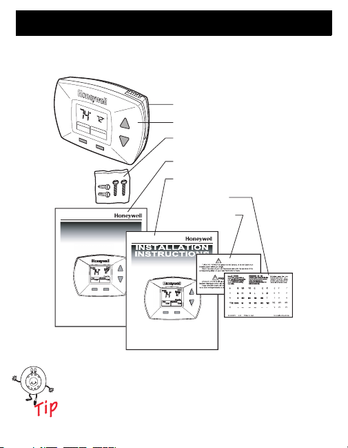
1. Check that the following items are included:
P
R
E
S
C
o
S
e
tti
ng
C
o
o
l
O
m
C
o
l
n
o
o
l
TIONS
S
WALLPLATE
THERMOSTAT
MOUNTING SCREWS (2)
AND WALL ANCHORS (2)
OPERATING INSTRUCTIONS
INSTALLATION INSTRUCTIONS
WIRE LABELS
CAUTION CARD
M22033
Inside
F
a
n
S
A
y
u
s
to
te
OPERATING
NSTRUC
I
If any of the items shown above are missing, call
Honeywell Customer Care at 1-800-468-1502
before returning the thermostat to the store.
3 69-1716
Page 4

Step 1. Prepare for Installation (Cont)
2. Check that you have everything required for
the installation:
• Two AAA alkaline batteries
• No. 2 Phillips screwdriver and standard pocket
screwdriver
• Drill
• Drill bit— use 3/16 in. for drywall; use 7/32 in.
for plaster
• Level (optional)
• Hammer
• Pencil
• Electrical tape
69-1716 4
Page 5
Step 2. Follow Important Instructions
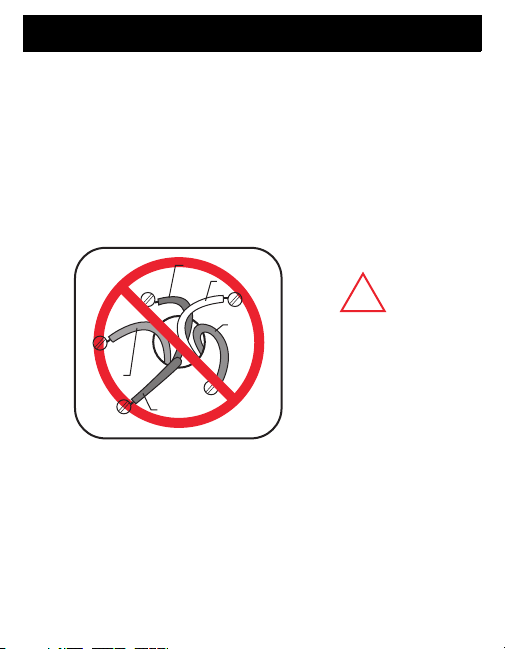
1. Do not connect the wires to the new thermostat
based on wire color because damage can occur to
the heating and/or cooling system.
These Installation Instructions explain later how to
use the enclosed wire labels to correctly mark the
wires connected to your old thermostat.
OLD THERMOSTAT
YELLOW
WHITE
R
RED
W
NEW THERMOSTAT
!
DO NOT WIRE
BASED ON
WIRE COLOR.
M22034
G
GREEN
RC
Y
ORANGE
Step 3. Remove Old Thermostat
5 69-1716
Page 6
Step 3. Remove Old Thermostat
1. Turn off power at the heating and/or cooling system
or fuse/circuit breaker panel.
2. Remove the cover from the old thermostat.
3. Remove the old thermostat from the wall or
wallplate. Do not remove the wires.
OLD THERM
Y
G
C
W
R
MERCURY NOTICE
If you are replacing a thermostat that contains mercury in a
sealed tube, do not place your old thermostat in the trash.
Contact your local waste management authority for instructions
regarding recycling and the proper disposal of an old thermostat
containing mercury in a sealed tube.
69-1716 6
OSTAT
WALLPLATE
.18
.2
.9
.7
.5
L
O
N
R
.4
G
E
.25
.3
THERMOSTAT
COVER
M22036
Page 7
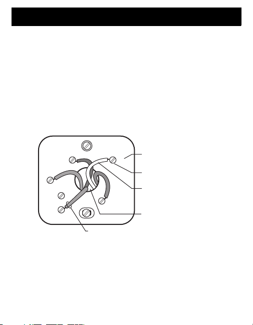
Step 4. Follow Special Instructions
1. If you have C and/or C1 wire(s) connected to your
old thermostat, do not connect them to your new
thermostat.
2. Disconnect the C and/or C1 wire(s). Make sure
they do not touch each other or any other wires.
3. Wrap the bare end of each C and/or C1 wire(s)
with electrical tape.
OLD THERM
Y
G
C
OSTAT
LETTER
W
DESIGNATION
SCREW
TERMINAL
WIRE
R
WIRE HOLE
DO NOT CONNECT TO NEW THERMOSTAT
M22037
7 69-1716
Page 8
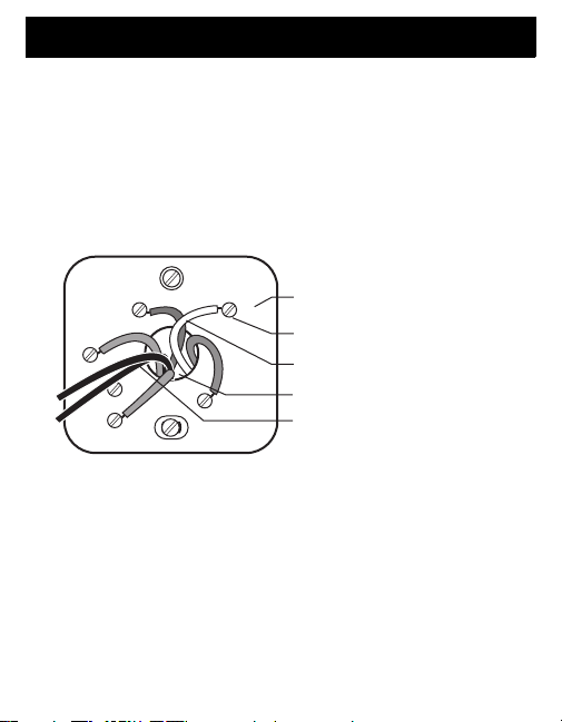
Step 4. Follow Special Instructions (Cont)
4. Most installations have two to five wires connected
to the old thermostat. If six or more wires are
connected to your old thermostat (not counting
the C or C1 wires), do not continue the installation.
You may have purchased the wrong thermostat.
Visit www.honeywell.com/yourhome or call
Honeywell Customer Care at 1-800-468-1502
before returning the thermostat to the store.
OLD THERM
Y1
G
W2
Y2
69-1716 8
OSTAT
SIX WIRES CONNECTED
LETTER
W1
DESIGNATION
SCREW
TERMINAL
WIRE
R
WIRE HOLE
M22038
Page 9
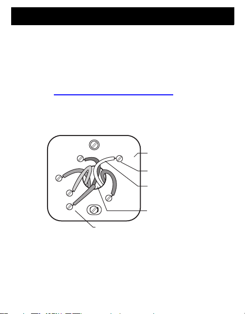
Step 4. Follow Special Instructions (Cont)
5. If you find any wires not connected to your old
thermostat, do not connect them to your new
thermostat.
6. Wrap the end of the wires that are not connected
with electrical tape.
OLD THERM
Y
G
RC
OSTAT
R
LETTER DESIGNATION
W
SCREW TERMINAL
WIRE
WIRE HOLE
WIRES NOT CONNECTED –
DO NOT CONNECT TO
NEW THERMOSTAT
M22040
Step 5. Label and Disconnect Wires from Old
Thermostat
9 69-1716
Page 10
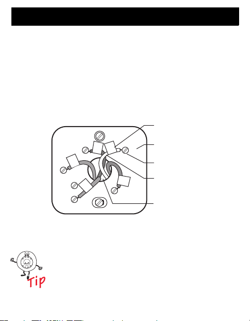
Step 5. Label Old Thermostat Wires
1. As you disconnect each wire, use the enclosed wire
labels to wrap a wire label around each wire that
matches the letter designation. Do not allow the
wires to fall into the wall opening after the wires
are disconnected.
2. Remove any remaining parts of the old thermostat
from the wall.
OLD THERM
Y
G
G
RC
C
R
Y
OSTAT
W
When connecting the wires to the new
thermostat, refer to the wire labels. Do not
connect wires to your new thermostat based
on the color of the wire.
69-1716 10
WIRE LABEL
LETTER
W
DESIGNATION
SCREW
TERMINAL
R
R
WIRE
WIRE HOLE
M22039
Page 11

Step 6. Mount New Wallplate to Wall
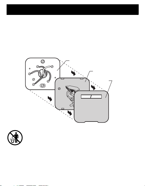
1. Separate the wallplate from the thermostat as
shown.
THERMOSTAT
WALLPLATE
WIRE HOLE
M22042
11 69-1716
Page 12

Step 6. Mount New Wallplate to Wall (Cont)
2. Pass the labeled wires through the wire hole on the
wallplate.
WALL OPENING
WALLPLATE
WIRE HOLE
RC
R
Y
NOT
USED
(O/B)
W
G
LABELED WIRES
69-1716 12
M22043
Page 13

Step 6. Mount New Wallplate to Wall (Cont)
3. Position the wallplate on the wall with the arrow
pointing up. Level the wallplate (for appearance
only) and mark the two mounting holes with
a pencil.
LEVEL
WALLPLATE
M22044
(O/B)
C
R
Y
NOT
USED
W
G
13 69-1716
MARK MOUNTING
HOLES (2)
R
PLACE LEVEL ON TABS
Page 14

Step 6. Mount New Wallplate to Wall (Cont)
4. Move the wallplate aside and drill holes at the
locations marked on the wall. Drill 3/16 in. holes
for drywall or 7/32 in. holes for plaster.
5. Tap the wall anchors into the drilled holes until even
with the wall surface.
DRILLED HOLES (2)
WALL
ANCHORS (2)
C
R
R
Y
NOT
USED
(O/B)
W
G
WALLPLATE
MOUNTING
SCREWS (2)
6. Position the wallplate over the wall anchors.
7. Insert the mounting screws into the wall anchors.
Check leveling, if desired, and tighten the mounting
screws.
69-1716 14
M22046
Page 15

Step 7. Connect Wires to New Wallplate
1. Match the labeled wires to the letter designations
on the wallplate.
2. If wires are to be connected to both Rc and R,
loosen the Rc and R screw terminals and remove
the metal jumper.
3. If only one of the terminals, Rc or R, is to be
connected, leave metal jumper in place.
METAL JUMPER
TERMINAL BLOCK
SCREW TERMINALS
LETTER
DESIGNATIONS
USED
O/B W
R
NOT
WALLPLATE
C
RC
R
Y
W/O/B
G
R
Y
G
15 69-1716
M22180
Page 16

Step 7. Connect Wires to New Wallplate (Cont)
4. Loosen the screw terminals. Insert the labeled
wires into the holes on the right side of the terminal
block that match the letter designations. Tighten the
screw terminals.
5. If any of the labeled wires do not match the letter
designations, see next page for wire connections.
LABELED WIRES
TERMINAL BLOCK
SCREW TERMINALS
LETTER
DESIGNATIONS
RC
R
Y
NOT
USED
O/B W
G
69-1716 16
WALLPLATE
RC
R
Y
W/O/B
G
WIRE HOLE
RC
R
Y
W
G
INSERT WIRE IN HOLE
M22176
Page 17

Step 7. Connect Wires to New Wallplate (Cont)
6. Compare letter designations on your old and new
thermostats.
New
Thermostat
1
C
R
1
R
Y
NOT
USED
O/B W
G
Do not connect more than one wire to each
terminal. Be sure to read the notes referenced in
the numbered triangles above. These numbered
notes appear on the next page.
Possible letter designations
on the labeled wires
Do Not Connect
or R
RC
or RH, 4, V
R
or Y1, M
Y
or W1, H, O, B
W
or F
G
or X, B
C
2
2
3
4
M22055
17 69-1716
Page 18

Step 7. Connect Wires to New Wallplate (Cont)
NOTES
1
If wires will be connected to both RC and R on the new
thermostat, remove metal jumper between R
metal jumper in place if only one of the terminals, R
be connected on the new thermostat.
If wires were connected to both R and RH terminals on the old
2
thermostat, remove metal jumper between R
thermostat. Connect the old R to the new R
the new R.
3
Do not connect both O and B when wiring to a heat pump.
Connect O to O/B W. Wrap the bare end of the B wire with
electrical tape and do not use.
Transformer common. Wrap the bare end of the wire with
4
electrical tape and do not use.
C and R. Leave
C or R, will
C and R on the new
C and the old RH to
M22050
69-1716 18
Page 19

Step 7. Connect Wires to New Wallplate (Cont)
7. Push excess wire back into the wall opening.
Keep wires in the shaded area.
WALLPLATE
R
C
R
Y
NOT
USED
(O/B)
W
G
WALL OPENING
WIRE
SHADED AREA
M22054
19 69-1716
Page 20

Step 8. Install Batteries
1. Install two fresh AAA alkaline batteries on the back
of the thermostat as marked on the battery holder.
BACK OF THERMOSTAT
BATTERY HOLDER
BATTERIES
After the thermostat is mounted on the wallplate,
the thermostat does not require removal from
the wallplate to replace the batteries. Refer to
the enclosed Operating Instructions (69-1722)
for more information on the removable battery
holder.
69-1716 20
M22056
Page 21

Step 9. Attach New Thermostat to Wallplate
1. Align the four tabs on the wallplate with the four
slots on the back of the thermostat.
WALLPLATE
TABS
RC
R
Y
NOT
USED
O/B W
G
TABS
2. Push the thermostat straight onto the wallplate until
it snaps into place.
3. Turn on the power at the heating and/or cooling
system or fuse/circuit breaker panel.
If the wires interfere with mounting the
thermostat to the wallplate, push the excess
wire back into the wall opening.
SLOTS ON
BACK OF
THERMOSTAT
M22057
21 69-1716
Page 22

Step 10. Configure Installer Setup
Replace Batt
Cool
On
Se
eeded
an
o
Cool
System
Replace Batt
Se
eeded
e
t
1. Use the Installer Setup Menu to match your new
thermostat to your heating and/or cooling system.
Follow the steps in this section to set up your
thermostat.
2. Enter the Installer Setup Menu by pressing and
holding the Up and Fan buttons at the same time,
for approximately five seconds, until the screen
changes.
rvice N
F
Aut
M22058
3. Release the buttons when the display on your
thermostat matches the display below.
rvice N
Don
Nex
M22121
69-1716 22
Page 23

10. Configure Installer Setup (Cont)
Replace Batt
Se
eeded
e
t
S
UP
4. Press the Up or Down button to select your setting
for Installer Setup Number 1 in the table below.
5. After you select your setting, press the Next button
to go to the next Installer Setup Number.
IN
TALLER SET
NUMBER
1 Heating
and/or
Cooling
System
Type
rvice N
Don
SETTING
UP BUTTON
Nex
electric heating with central air
conditioning.
outside runs in both heating and
cooling.
heating without central air
conditioning.
or electric heating without central air
conditioning. (Use this setting if you
could turn the fan on and off with a
fan switch on your old thermostat.)
DOWN BUTTON
NEXT BUTTON
Gas, oil or
The compressor
Gas, oil or electric
Gas, oil
M22122
23 69-1716
Page 24

Configure Installer Setup (Cont)
Replace Batt
Se
eeded
e
t
S
UP
6. If you do not have a number 2 on the left side of
your display, go to the next page.
7. If you have a number 2 on the left side of your
display, press the Up or Down button to select your
setting for Installer Setup Number 2 in table below.
8. After you select your setting, press the Next button
to go the next Installer Setup Number.
IN
TALLER SET
NUMBER
2 Heat
Pump
Change-
over
Valve
69-1716 24
SETTING
UP BUTTON
rvice N
Don
Nex
DOWN BUTTON
NEXT BUTTON
Use this setting if you connected a
wire labeled O to O/B W terminal.
Use this setting if you connected a
wire labeled B to O/B W terminal.
M22060
Page 25

Step 10. Configure Installer Setup (Cont)
Replace Batt
Se
eeded
e
t
S
UP
9. If you do not have a number 3 on the left side of
your display, go to the next page.
10. If you have a number 3 on the left side of your
display, press the Up or Down button to select your
setting for Installer Setup Number 3 in table below.
11. After you select your setting, press the Next button
to go to the next Installer Setup Number.
IN
TALLER SET
NUMBER
3Fan
Control in
Heating
SETTING
UP BUTTON
rvice N
Don
Nex
DOWN BUTTON
NEXT BUTTON
Heating system
controls fan in a call for heat.
Thermostat controls
fan in a call for heat.
25 69-1716
M22061
Page 26

Step 10. Configure Installer Setup (Cont)
Replace Batt
Se
eeded
e
t
S
UP
12. If you do not have a number 5 on the left side of
your display, go to the next page.
13. If you have a number 5 on the left side of your
display, press the Up or Down button to select your
setting for Installer Setup Number 5 in table below.
14. After you select your setting, press the Next button
to go to the next Installer Setup Number.
IN
TALLER SET
NUMBER
5 Heating
Cycle
Rate
69-1716 26
SETTING
UP BUTTON
rvice N
Don
Nex
DOWN BUTTON
NEXT BUTTON
M22062
Page 27

Step 10. Configure Installer Setup (Cont)
e
t
S
UP
15. Press the Up or Down button to select your setting
for Installer Setup Number 14 in table below.
16. After you select your setting, press the Done button
to exit the Installer Setup and save your settings.
17. Congratulations! The installation of the thermostat
is complete. Refer to the enclosed Operating
Instructions (69-1722) for information on how to
operate your new thermostat.
IN
TALLER SET
NUMBER
DONE
BUTTON
Installer
Setup
Number
14 Tempera-
Installer
Setup
Name
ture
Display
SETTING
UP BUTTON
Don
Nex
DOWN BUTTON
(Select Your Setting)
Settings
0—Fahrenheit Temperature Display
1—Celsius Temperature Display
27 69-1716
M22063
Page 28

Customer Assistance
For assistance with your Honeywell product please visit
www.honeywell.com/yourhome or call Honeywell
Customer Care toll free at 1-800-468-1502.
Before calling, please have the thermostat model number
and date code available.
MODEL NUMBER DATE CODE
xxxxxxxx
69-1716 28
xxxxxx
THERMOSTAT
BATTERY HOLDER
M22178
Page 29

Limited One-Year Warranty
Honeywell warrants this product, excluding battery, to be free from defects
in the workmanship or materials, under normal use and service, for a
period of one (1) year from the date of purchase by the consumer. If, at any
time during the warranty period, the product is defective or malfunctions,
Honeywell shall repair or replace it (at Honeywell’s option) within a
reasonable period of time.
If the product is defective,
(i) return it, with a bill of sale or other dated proof of purchase, to the
retailer from which you purchased it, or
(ii) package it carefully, along with proof of purchase (including date of
purchase) and a short description of the malfunction, and mail it,
postage prepaid, to the following address:
Honeywell Return Goods
Dock 4 MN10-3860
1885 Douglas Dr N
Golden Valley, MN 55422
This warranty does not cover removal or reinstallation costs. This warranty
shall not apply if it is shown by Honeywell that the defect or malfunction
was caused by damage which occurred while the product was in the
possession of a consumer.
Honeywell’s sole responsibility shall be to repair or replace the product
within the terms stated above. HONEYWELL SHALL NOT BE LIABLE
FOR ANY LOSS OR DAMAGE OF ANY KIND, INCLUDING ANY
INCIDENTAL OR CONSEQUENTIAL DAMAGES RESULTING,
DIRECTLY OR INDIRECTLY, FROM ANY BREACH OF ANY
WARRANTY, EXPRESS OR IMPLIED, OR ANY OTHER FAILURE OF
THIS PRODUCT. Some states do not allow the exclusion or limitation of
incidental or consequential damages, so this limitation may not apply to
you.
29 69-1716
Page 30

Limited One-Year Warranty (Cont)
THIS WARRANTY IS THE ONLY EXPRESS WARRANTY HONEYWELL
MAKES ON THIS PRODUCT. THE DURATION OF ANY IMPLIED
WARRANTIES, INCLUDING THE WARRANTIES OF
MERCHANTABILITY AND FITNESS FOR A PARTICULAR PURPOSE, IS
HEREBY LIMITED TO THE ONE-YEAR DURATION OF THIS
WARRANTY. Some states do not allow limitations on how long an implied
warranty lasts, so the above limitation may not apply to you.
This warranty gives you specific legal rights, and you may have other
rights which vary from state to state.
If you have any questions concerning this warranty, please write
Honeywell Customer Relations, 1985 Douglas Dr, Golden Valley, MN
55422 or call 1-800-468-1502. In Canada, write Retail Products
ON15-02H, Honeywell Limited/Honeywell Limitée, 35 Dynamic Drive,
Scarborough, Ontario M1V4Z9.
69-1716 30
Page 31

31 69-1716
Page 32

Automation and Control Solutions
Honeywell International Inc. Honeywell Limited-Honeywell Limitée
1985 Douglas Drive North 35 Dynamic Drive
Golden Valley, MN 55422 Scarborough, Ontario
69-1716 G.H. 5-04 www.honeywell.com/yourhome
M1V 4Z9
 Loading...