

Page 1
Operating Instructions
RTH5100B
Non-programmable Thermostat
OPERATING INSTRUCTIONS
The RTH5100B Thermostat provides electronic control of 24 Vac single
stage heating and cooling systems or 750 mV heating systems.
For assistance with your Honeywell product please visit
www.honeywell.com/yourhome
toll free at 1-800-468-1502.
or call Honeywell Customer Care
Read and Save these Instructions
® U.S. Registered Trademark
© 2004 Honeywell International Inc.
All Rights Reserved • Patents Pending
69-1722
Page 2

Contents
Features........................................................................3
Get to Know Your Thermostat ......................................4
Thermostat...............................................................4
Display .....................................................................5
Operate Your Thermostat .............................................6
Set System Setting ..................................................6
Set Fan Setting ........................................................7
Change Temperature Setting...................................8
Replace Batteries .........................................................9
Review Battery Tips......................................................13
Built-in Compressor Protection.....................................14
Accessory/Replacement Parts......................................15
Troubleshooting Tips ....................................................16
Customer Assistance....................................................21
Limited One-Year Warranty ..........................................22
69-1722 2
Page 3

Features
• Large, Clear, Backlit Display: Easy-to-see and
read—even in the dark.
• Precise Comfort Control: ±1ºF of your set
temperature.
• Simplified Operation: Soft-key controls.
Simultaneously displays both room temperature
and temperature setting.
• Easy Change Battery Holder.
• Built-in Compressor Protection: Minimum-off
timer protects compressor from restarting too
early after a shutdown.
Get To Know Your Thermostat
3 69-1722
Page 4
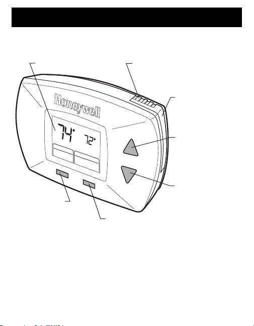
Thermostat
Get To Know Your Thermostat
DIGITAL DISPLAY
Inside
Cool
Setting
Fan
Cool
System
Auto
FAN BUTTON
SELECTS AUTO OR ON
69-1722 4
On
Cool
SYSTEM BUTTON
SELECTS HEAT, OFF OR COOL
BATTERY HOLDER LATCH
PRESS TO RELEASE
BATTERY HOLDER.
PRESS
BATTERY
HOLDER
TWO AAA
ALKALINE
BATTERIES
TEMPERATURE
SETTING BUTTON
RAISES
TEMPERATURE
SETTING
TEMPERATURE
SETTING BUTTON
LOWERS
TEMPERATURE
SETTING
M22010
Page 5
Get to Know Your Thermostat (Cont)
Replace Batt
eat
Cool
S
g
eat
de
an
O
o
eat
System
E
O
D
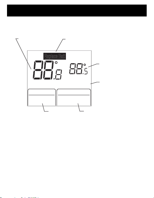
Display
INSIDE
TEMPERATUR
Insi
F
n Aut
INDICATES BATTERIES ARE
L
W AND MUST BE REPLACE
CoolH
ettin
On
H
On
H
Cool
Off
CURRENT
FAN SETTING
CURRENT
SYSTEM SETTING
5 69-1722
TEMPERATURE
SETTING
INDICATES
THERMOSTAT IS
"CALLING" FOR
HEAT OR COOL
M22011
Page 6
Operate Your Thermostat
Cool
On
Se
eeded
an
o
Coo
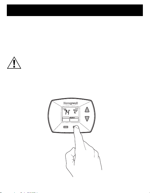
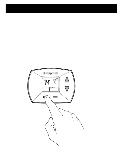
Set System Setting
Press the System button to select Heat, Off or Cool:
Heat—Thermostat controls the heating system.
Off—Both the heating and cooling systems are off.
Cool—Thermostat controls the cooling system.
CAUTION
Equipment Damage Hazard.
Air conditioning compressor damage possible.
Do not operate cooling system when outdoor temperature
is below 50 °F (10 °C).
rvice N
F
l
Aut
PRESS THE
SYSTEM BUTTON
TO SELECT HEAT,
OFF OR COOL
M22012
69-1722 6
Page 7
Operate Your Thermostat (Cont)
C
On
Se
eeded
an
o
Cool
A
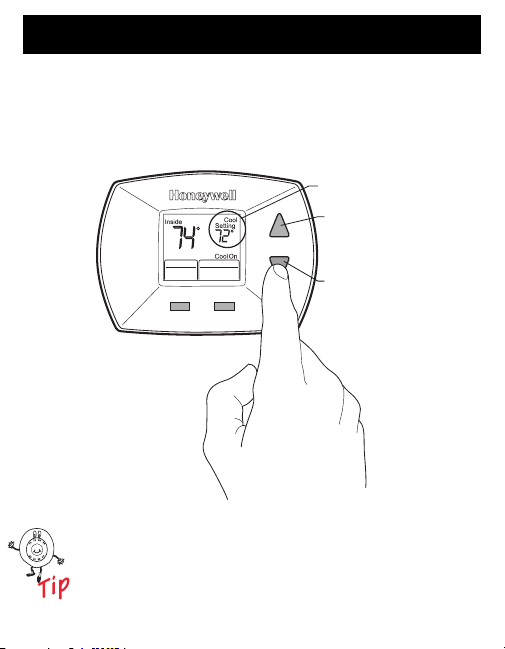
Set Fan Setting
Press the Fan button to select Auto or On:
Auto—Normal setting for most homes.The fan runs
only when the heating or cooling system is on.
On—The fan runs continuously. Use this setting for
improved air circulation or for more efficient air
cleaning.
rvice N
ool
F
Aut
PRESS THE
FAN BUTTON
TO SELECT
UTO OR ON
M22013
7 69-1722
Page 8
Operate Your Thermostat (Cont)
Replace Batt
Se
eeded
an
o
Cool
System
Change Temperature Setting
Press the Up or Down button to select the desired
temperature setting.
TEMPERATURE
SETTING
PRESS THIS
BUTTON TO RAISE
THE TEMPERATURE
rvice N
F
Aut
TEMPERATURE SETTING RANGE:
HEAT: 40°TO 90°F (4.5°T0 32°C)
COOL: 50°TO 99°F (10° T0 37°C)
The first press of the Up or Down button turns on
the backlight. The second press of the Up or Down
button changes the temperature setting.
SETTING
PRESS THIS
BUTTON TO LOWER
THE TEMPERATURE
SETTING
M22014
69-1722 8
Page 9

Replace Batteries
t
S
d
an
o
Cool
System
1. When the Replace Battery indicator is flashing,
replace batteries promptly with two fresh
AAA alkaline batteries.
REPLACE BATTERY INDICATOR
Replace Bat
ervice Neede
F
Aut
M22015
The thermostat does not lose any settings
when the batteries are replaced; all settings
are permanently stored in memory.
9 69-1722
Page 10

Replace Batteries (Cont)
S
d
an
o
Cool
2. Press the battery holder latch to release the battery
holder.
3. Remove the battery holder from the thermostat.
BATTERY HOLDER
F
LATCH
ervice Neede
Aut
69-1722 10
BATTERY HOLDER
M22016
Page 11

Replace Batteries (Cont)
4. Remove the old batteries and insert two fresh
AAA alkaline batteries as marked on the battery
holder.
BATTERY
HOLDER
PUSH
BATTERIES
OUT
THROUGH
THIS HOLE
BATTERY
DIRECTION
M22017
11 69-1722
Page 12

Replace Batteries (Cont)
S
d
an
o
Cool
5. Insert battery holder as shown.
BATTERY HOLDER
F
LATCH
ervice Neede
Aut
69-1722 12
BATTERY HOLDER
M22016
Page 13

Review Battery Tips
1. Replace the batteries as soon as Replace Batt
flashes in the display. The Replace Battery
indicator flashes in the display two months before
the batteries run down completely.
2. Always use fresh AAA alkaline batteries.
Non-alkaline batteries do not last as long and can
leak, causing thermostat damage.
3. Although the thermostat has a Replace Battery
indicator, replace the batteries once a year to
prevent the thermostat and heating/cooling system
from shutting down due to lack of battery power.
NOTE: Replacing the batteries once a year also helps
prevent battery leakage that can damage the
thermostat.
4. As a precaution, replace the batteries when leaving
your home for more than a month to prevent your
heating/cooling system from shutting down if the
batteries run down completely.
13 69-1722
Page 14

Built-in Compressor Protection
The RTH5100B Thermostat has built-in compressor
protection (minimum-off timer) that prevents the
compressor from restarting too early after a shutdown.
The minimum-off timer is activated after the compressor
turns off.
If there is a call during the minimum-off timer, the
thermostat flashes “Cool On” or “Heat On”a in the display.
When the minimum-off timer expires, “Cool On” or “Heat
On”a appears solidly in the display and the compressor
and fan turn on.
________
a
Heat Pumps only.
69-1722 14
Page 15

Accessory/Replacement Parts
1. Cover Plates—Used to cover marks on the wall
Part Number:
50001137-001 (Small) Cover Plate
50002883-001 (Large) Cover Plate
To order, call Honeywell Customer Care at
1-800-468-1502.
M22185
2. Replacement Battery Holder—
Part Number 50000951-001 Battery Holder
To order, call Honeywell Customer Care at
1-800-468-1502.
15 69-1722
Page 16

Troubleshooting Tips
If . . . Then . . .
Display is
blank.
Temperature
settings do
not change.
Heating
system does
not turn on.
69-1722 16
Check that fresh AAA alkaline batteries
are installed as marked on the battery
holder.
Check that the temperature settings are:
• Heating 40°F to 90°F(4.5°C to 32°C).
• Cooling 50°F to 99°F (10°C to 37°C).
• Set the system to Heat by pressing
the System button.
• Check the heat temperature setting to
be sure it is set above the room
temperature and “Heat On” shows
solidly in the display.
• Check the circuit breaker to be sure it
is not tripped.
• Check power switch at heating and/or
cooling system to be sure it is on.
• Check the furnace door to be sure it is
closed securely.
• Wait five minutes for the heating
system to respond.
• If all of this was checked, contact your
local heating and cooling contractor.
Page 17

Troubleshooting Tips (Cont)
If . . . Then . . .
Cooling
system does
not turn on.
Cannot set
System
setting to
Cool.
• Set the system to Cool by pressing
the System button.
• Check the cool temperature setting to
be sure it is set below the room
temperature and “Cool On” shows
solidly in the display.
• Check the circuit breaker to be sure it
is not tripped.
• Check the power switch at the heating
and/or cooling system to be sure it is
on.
• Check the furnace door to be sure it is
closed securely.
• Wait five minutes for the cooling
system to respond.
• If all of this was checked, contact your
local heating and cooling contractor.
Check Installer Setup Number 1, Heating
and/or Cooling System Type; make sure
the setting matches the installed heating
and/or cooling system. Refer to
Installation Instructions, 69-1716.
17 69-1722
Page 18

Troubleshooting Tips (Cont)
If . . . Then . . .
“Heat On” is
not shown in
the display.
“Cool On” is
not shown in
the display.
“Heat On” is
flashing in the
display (heat
pumps only).
“Cool On” is
flashing in the
display.
Set the System setting to Heat and set
the temperature setting above the room
temperature. If “Heat On” is shown
solidly in the display, but the heating
system does not turn on, see “Heating
system does not turn on” in
theTroubleshooting Tips.
Set the System setting to Cool and set
the temperature setting below the room
temperature. If “Cool On” is shown solidly
in the display, but the cooling system
does not turn on, see “Cooling system
does not turn on” in the Troubleshooting
Tips.
Compressor minimum-off timer is active.
Wait up to five minutes for the heating
system to turn on.
Compressor minimum-off timer is active.
Wait up to five minutes for the cooling
system to turn on.
69-1722 18
Page 19

Troubleshooting Tips (Cont)
If . . . Then . . .
Fan does not
turn on in a
call for heat
(electric
furnaces
only).
Heat pump
puts out cool
air in the heat
mode and
warm air in
the cool
mode (heat
pumps only).
Both the
heating and
cooling
systems are
running at the
same time.
Check Installer Setup Number 3, Fan
Control in Heating, and make sure it is
set to Electric Heat (Setting 1).Refer to
Installation Instructions, 69-1716
Check Installer Setup Number 2, Heat
Pump Changeover Valve, and make sure
the setting matches the changeover
required by the installed heat pump.
Refer to Installation Instructions,
69-1716.
Check Installer Setup Number 1, Heating
and/or Cooling System Type, and make
sure the setting matches the installed
heating and/or cooling system. Refer to
Installation Instructions, 69-1716.
Check and make sure the bare portions
of the wires are not touching.
19 69-1722
Page 20

Troubleshooting Tips (Cont)
If . . . Then . . .
Heating
system is
running in
cool mode.
Heating
system does
not turn off
and the heat
temperature
setting is set
below the
room
temperature
(“Heat On” is
not shown in
the display).
Check Installer Setup Number 1, Heating
and/or Cooling System Type, and make
sure the setting matches the installed
heating and/or cooling system. Refer to
Installation Instructions, 69-1716.
Check Installer Setup Number 1, Heating
and/or Cooling System Type, and make
sure the setting matches the installed
heating and/or cooling system. Refer to
Installation Instructions, 69-1716.
69-1722 20
Page 21

Customer Assistance
For assistance with your Honeywell product please visit
www.honeywell.com/yourhome or call Honeywell
Customer Care toll free at 1-800-468-1502.
Before calling, please have the thermostat model number
and date code available.
MODEL NUMBER DATE CODE
xxxxxxxx
xxxxxx
THERMOSTAT
BATTERY HOLDER
Limited One Year Warranty…
21 69-1722
M22178
Page 22

Limited One-Year Warranty
Honeywell warrants this product, excluding battery, to be free from defects
in the workmanship or materials, under normal use and service, for a
period of one (1) year from the date of purchase by the consumer. If, at any
time during the warranty period, the product is defective or malfunctions,
Honeywell shall repair or replace it (at Honeywell’s option) within a
reasonable period of time.
If the product is defective,
(i) return it, with a bill of sale or other dated proof of purchase, to the
retailer from which you purchased it, or
(ii) package it carefully, along with proof of purchase (including date of
purchase) and a short description of the malfunction, and mail it,
postage prepaid, to the following address:
Honeywell Return Goods
Dock 4 MN10-3860
1885 Douglas Dr N
Golden Valley, MN 55422
This warranty does not cover removal or reinstallation costs. This warranty
shall not apply if it is shown by Honeywell that the defect or malfunction
was caused by damage which occurred while the product was in the
possession of a consumer.
Honeywell’s sole responsibility shall be to repair or replace the product
within the terms stated above. HONEYWELL SHALL NOT BE LIABLE
FOR ANY LOSS OR DAMAGE OF ANY KIND, INCLUDING ANY
INCIDENTAL OR CONSEQUENTIAL DAMAGES RESULTING,
DIRECTLY OR INDIRECTLY, FROM ANY BREACH OF ANY
WARRANTY, EXPRESS OR IMPLIED, OR ANY OTHER FAILURE OF
THIS PRODUCT. Some states do not allow the exclusion or limitation of
incidental or consequential damages, so this limitation may not apply to
you.
69-1722 22
Page 23

Limited One-Year Warranty (Cont)
THIS WARRANTY IS THE ONLY EXPRESS WARRANTY HONEYWELL
MAKES ON THIS PRODUCT. THE DURATION OF ANY IMPLIED
WARRANTIES, INCLUDING THE WARRANTIES OF
MERCHANTABILITY AND FITNESS FOR A PARTICULAR PURPOSE, IS
HEREBY LIMITED TO THE ONE-YEAR DURATION OF THIS
WARRANTY. Some states do not allow limitations on how long an implied
warranty lasts, so the above limitation may not apply to you.
This warranty gives you specific legal rights, and you may have other
rights which vary from state to state.
If you have any questions concerning this warranty, please write
Honeywell Customer Relations, 1985 Douglas Dr, Golden Valley, MN
55422 or call 1-800-468-1502. In Canada, write Retail Products
ON15-02H, Honeywell Limited/Honeywell Limitée, 35 Dynamic Drive,
Scarborough, Ontario M1V4Z9.
23 69-1722
Page 24

Automation and Control Solutions
Honeywell International Inc. Honeywell Limited-Honeywell Limitée
1985 Douglas Drive North 35 Dynamic Drive
Golden Valley, MN 55422 Scarborough, Ontario
69-1722 G.H. 5-04 www.honeywell.com/yourhome
M1V 4Z9
 Loading...