

Page 1
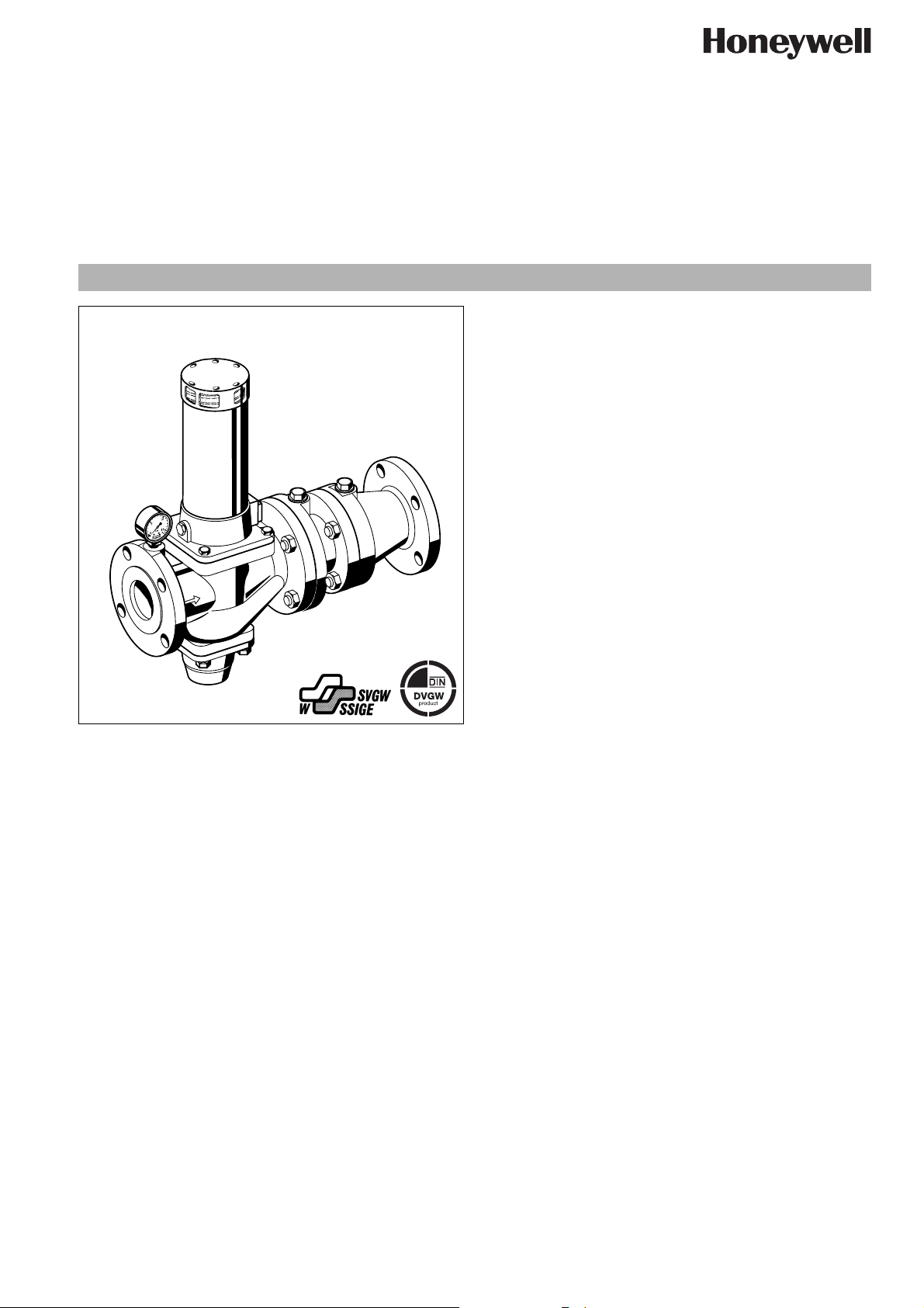
Mechanical disconnector with flanges direct actuated
GB type according to EN
Construction
The mechanical disconnectors comprises:
• Housing with pressure gauge
• Outlet check valve
• Spring bonnet
• PN 16 flanged connections to ISO 7005-2, DIN EN 1092-2
• Drain connector
• Valve insert with spring
• Spindle guide with double O-ring seal
Materials
• Grey cast iron housing, powder coated inside and outside
• Steel spring bonnet
• NBR seals
• Stainless steel valve stem and spring
• Red bronze for other internal parts
• Red bronze drain connector up to DN 100, Grey cast iron
drain connector DN 125 - DN 200, powder coated inside and
outside
• Chrome plated balanced-seat piston
• High grade synthetic material bearing surfaces for sliding in-
EN0H-1211GE23 R0206 y Subject to change without notice
ternal parts
1717/ type 1 according to DIN1988 part 4
R295P-F
Product specification sheet
Application
Mechanical disconnectors of this type are suitable for the protection of drinking water systems as required by EN 1717 "The technical regulation of drinking water systems" and correspond to
DIN1988 part 4 type 1 construction.
Their purpose is to protect systems against back pressure, back
flow and back syphonage of non-potable water into the public
water supply network.
Mechanical disconnectors can be used to provide protection up
to and including liquid category 3 (slightly toxic substances) and
therefore offer better protection than check valves.
Special Features
• DIN/DVGW and SVGW approvals in all connection sizes
• Optimal protection of the drinking water supply system
• Enhanced protection against back pressure, back flow and
back syphonage into the water supply network
• Shutoff position visually indicated on the spring bonnet
• Compact construction
• Powder coated inside and outside - Powder used is physiologically and toxicologically safe
• Meets KTW recommendations for potable water
• Low pressure loss and high flow rate
Range of Application
Medium Cold water
Max. inlet pressure 16.0 bar
Technical Data
Installation position Horizontal with spring bonnet upwards
Max. operating
temperature
Opening pressure 0.5, 1.0, 1.5 or 2.0 bar as required
Minimum inlet pressure
Connection size DN 65 - 200
40°C
(DN 65 - DN 100)
0.5, 1.0 bar as required
(DN 125 - DN 200)
= opening pressure + 1,0 bar
www.honeywell.com 37
Page 2
R295P-F Mechanical disconnector with flanges direct actuated
Method of Operation
Type 1 mechanical disconnectors remain in the flow position and
change to the shutoff position only when the inlet pressure falls
below the design opening pressure.
The inlet pressure operates on the annular surface of the valve piston and pushes it against the force of the spring bringing the piston to the open position. If the supply pressure falls below the
opening pressure needed to overcome the spring force (for example because of a broken pipe or during service work by the
supply undertaking) then the integral spring pushes the valve into
the closed position.
Options
R295P-... FA = With flanges, 0.5 bar opening pressure
R295P-... FB = With flanges, 1.0 bar opening pressure (stan-
dard pattern)
R295P-... FC = With flanges, 1.5 bar opening pressure
(DN 65 - DN 100 only)
Special Versions available on request
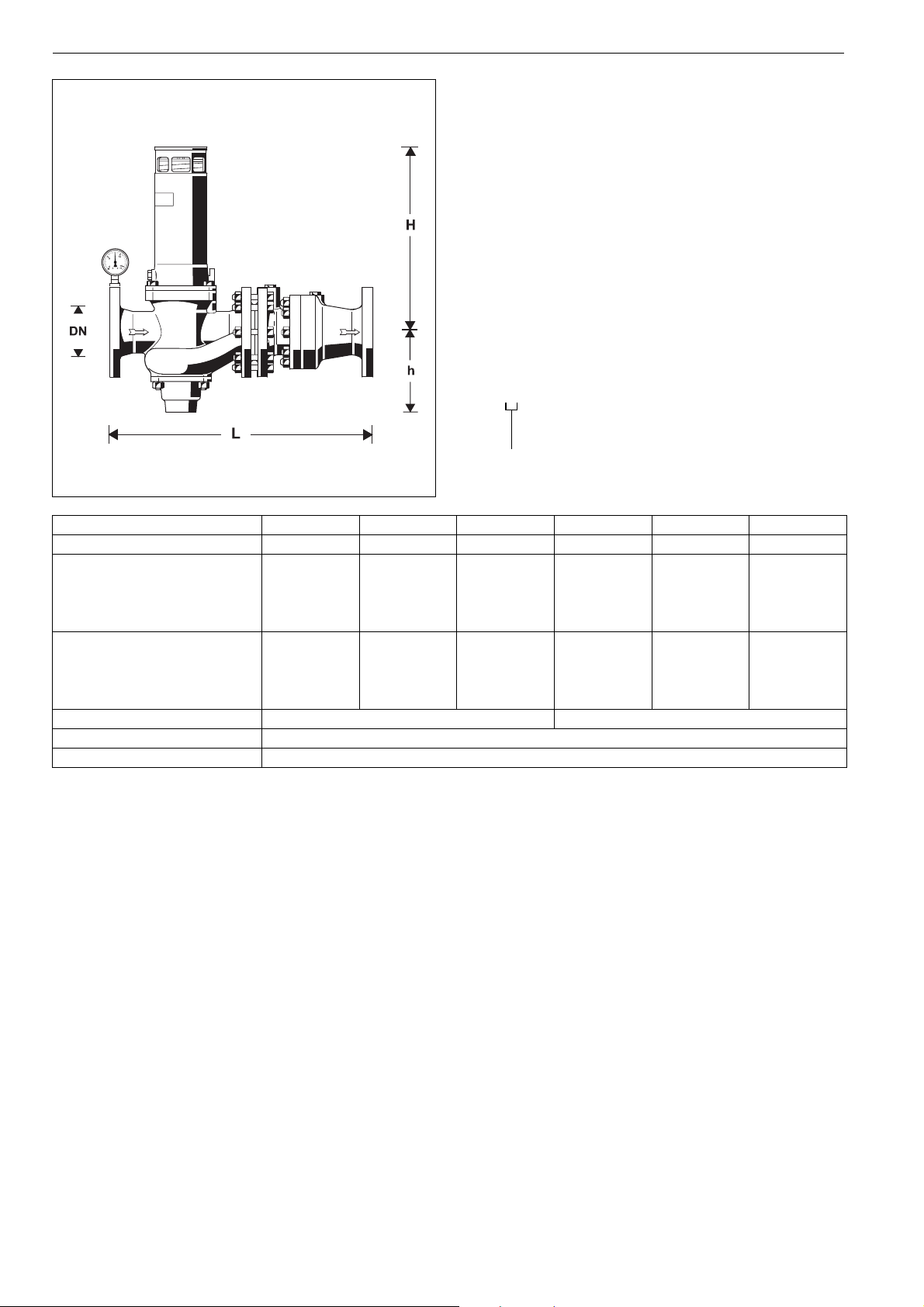
Connection size
Connection size DN 65 80 100 125 150 200
Weight approx. kg 48 67 89 145 206 408
Dimensions mm
L 532 572 652 752 882 1102
H 380 495 475 528 563 851
h 165 208 232 280 313 438
Nominal flow rate m
3
/h
at ∆p = 0.3 bar 27 34 68 114 150 198
kvs-value (full flow) 50 62 125 208 274 362
ξ value 111710 9 1019
Opening pressure 0.5, 1.0 or 1.5 bar as required 0.5 or 1.0 bar as required
DIN/DVGW Approval No. NW - 6301 AT 2322
SVGW Approval No. 8309-1381
38 www.honeywell.com
EN0H-1211GE23 R0206 y Subject to change without notice
Page 3

Installation Example
R295P-F Mechanical disconnector with flanges direct actuated
Installation Guidelines
• Install shutoff valves
• Install in horizontal pipework with spring bonnet directed upwards
o This orientation ensures optimum performance
• Ensure good access
o Pressure gauge can be read off easily
o Simplifies maintenance and inspection
• Mechanical disconnectors must not be fitted in any areas or
ducts where poisonous gases or vapours may be present or
where flooding can occur
Flow Diagram
Typical Applications
Mechanical disconnectors of this type are best suited for commercial and industrial applications.
However they can also be used for supplies to residential buildings within the scope of their specification.
The following are some typical applications:
• Softening and deacidification plants without DVGW approval
• Soda machines
• Boilers and automatic pressure fermentation equipment
• Heating system filling assemblies without DVGW approval,
water without inhibitors
• Air conditioners
EN0H-1211GE23 R0206 y Subject to change without notice
www.honeywell.com 39
Page 4

R295P-F Mechanical disconnector with flanges direct actuated
DN 50 - 150
DN 200
Spare Parts
Mechanical disconnector R295P-F
No. Description Dimension Part No.
c Valve insert complete
0.5 bar DN 65 R295AP-65FA
DN 80 R295AP-80FA
DN 100 R295AP-100FA
DN 125 R295AP-125FA
DN 150 R295AP-150FA
DN 200 R295AP-200FA
1.0 bar DN 65 R295AP-65FB
DN 80 R295AP-80FB
DN 100 R295AP-100FB
DN 125 R295AP-125FB
DN 150 R295AP-150FB
DN 200 R295AP-200FB
1.5 bar DN 65 R295AP-65FC
DN 80 R295AP-80FC
DN 100 R295AP-100FC
d Set of seals DN 65 0901093
DN 80 0901094
DN 100 0901095
DN 125 0901143
DN 150 0901145
DN 200 0901147
e Lip seal ring DN65 5350000
DN80 5350300
DN100 5350400
DN125 2070300
DN150 2067300
DN200 2238900
f Valve disc complete DN 65 0900376
DN 80 0900377
DN 100 0900378
DN 125 0900379
DN 150 0900380
DN 200 0900381
g Pressure gauge M39M-A16
Ranges 0 - 16 bar
h Pressure gauge M07M-A16
Ranges 0 - 16 bar
i Hexagon-plug all S06M-1/4
1
with O-ring R
/4"
(5 pcs.)
Automation and Control Solutions
Honeywell GmbH
Hardhofweg
D-74821 Mosbach
Phone: (49) 6261 810
Fax: (49) 6261 81309
http://europe.hbc.honeywell.com
www.honeywell.com
Manufactured for and on behalf of the
Environmental and Combustion Controls Division
of Honeywell Technologies Sàrl, Ecublens, Route
du Bois 37, Switzerland by its Authorised Representative Honeywell GmbH
EN0H-1211GE23 R0206
Subject to change
© 2006 Honeywell GmbH
 Loading...