

Page 1
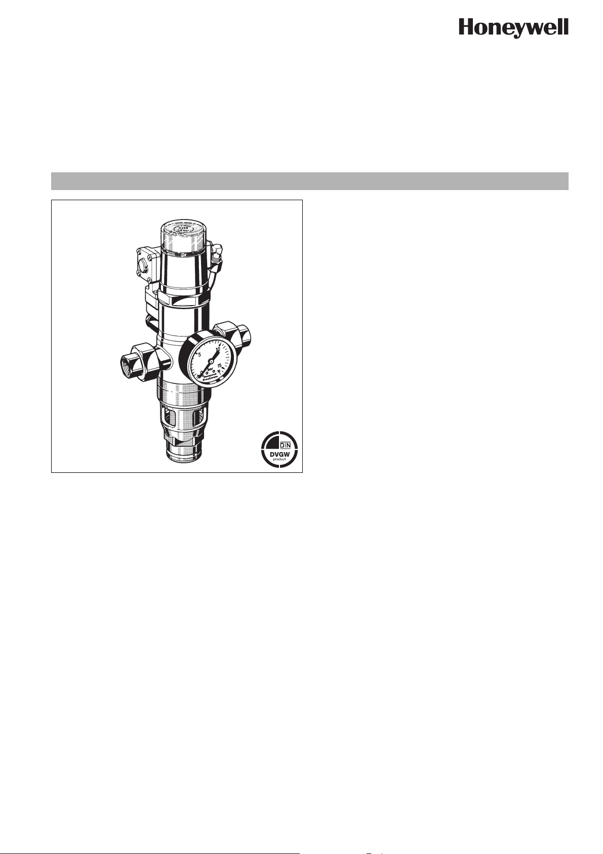
R295H
Mechanical disconnector hydraulic actuated
GB type according to EN1717/ type 2 according to DIN1988 part 4
Product specification sheet
Application
Mechanical disconnectors of this type are suitable for the protection of drinking water systems as required by EN 1717 "The technical regulation of drinking water systems" and correspond to
DIN1988 part 4 type 2 construction.
Their purpose is to protect systems against back pressure, back
flow and back syphonage of non-potable water into the public
water supply network.
Mechanical disconnectors of this type can be used to provide
protection up to and including liquid category 4 (toxic, very toxic,
carcinogenic and radioactive substances).
Special Features
• DIN/DVGW approvals in all connection sizes
• Optimal protection of the drinking water supply system
• Enhanced protection against back pressure, back flow and
back syphonage into the water supply network
• Shutoff position visually indicated on the spring bonnet
• Compact construction
• Standardised discharge connection
• Meets KTW recommendations for potable water
Construction
The mechanical disconnectors comprises:
• Housing with pressure gauge
• Outlet differential pressure transducer
• Threaded union connectors
• Hydraulically controlled changeover valve
• Pressure shock damper
• Valve insert with spring
• Discharge connection
• Spring bonnet
• Spindle guide with double O-ring seal
Materials
• Red bronze housing
• Brass union nuts
• Red bronze threaded union connectors (brass for 2")
• High quality synthetic material spring bonnet
• Red bronze changeover valve
• NBR seals
• High grade corrosion resistant synthetic material for other
EN0H-1206GE23 R0206 y Subject to change without notice
internal parts
• Stainless steel valve stem and spring
• High quality synthetic material discharge connection
• Brass outlet differential pressure transducer
•Low pressure loss
Range of Application
Medium Cold water
Max. inlet pressure 16.0 bar
Technical Data
Installation position Horizontal with spring bonnet upwards
Max. operating
temperature
Minimum inlet pressure
Minimum flow rate 1.0 l/min
Connection size
40°C
1.5 bar
1
/2“ - 2“
www.honeywell.com 29
Page 2
R295H Mechanical disconnector hydraulic actuated
Method of Operation
Mechanical disconnectors this type are normally in the shutoff
position.
When the outlet pressure drops due to water consumption, the
differential pressure in the disconnector rises. If the differential
pressure rises above 0.5 bar, the hydraulic operator causes the
control valve to changeover the mechanical disconnectors into
the flow position. When the water consumption stops, the differential pressure decreases and the differential pressure transducer transmits a signal to the control valve, which then returns the
disconnector to the normal shutoff position.
Options
R295H-... A = With female threaded union connectors,
differential pressure 0.5 bar, self-adjusting
Special Versions available on request
Connection size
Connection size R
1
/2"
3
/4"1"1
1
/4"1
1
/2"2"
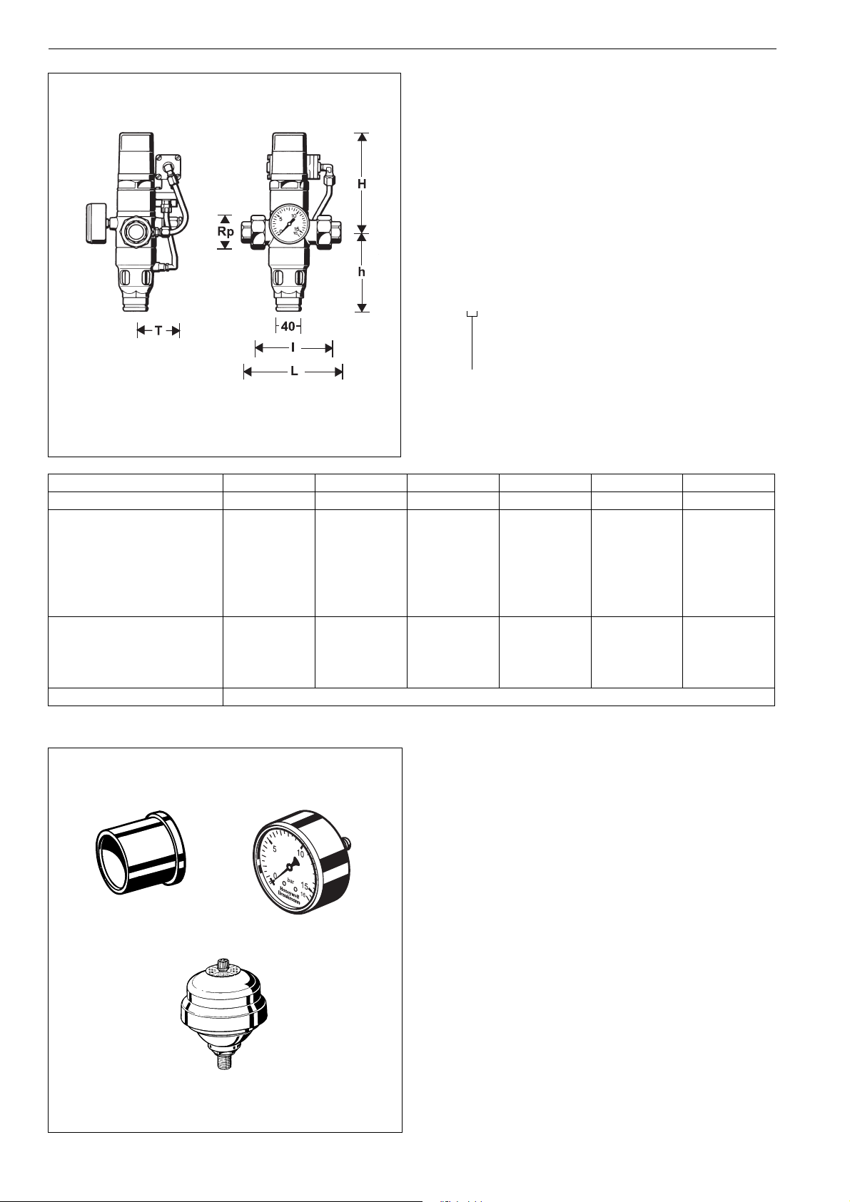
Weight approx. kg 1.4 1.6 1.8 4.3 4.9 5.3
Dimensions mm
L 151 153 159 216 228 241
l 105 105 105 150 160 165
H 153 155 155 232 231 224
h 125 123 123 155 159 166
T768080939398
3
Nominal flow rate m
/h
at ∆p = 0.8 bar 2.2 3.1 3.6 8.9 12.5 14.3
-value 2.5 3.5 4.0 10.0 14.0 16.0
k
vs
ξ value 13.0 20.9 39.0 16.8 20.9 39.0
DIN/DVGW Approval No. NW - 6301 AT 2320
Accessories
M07M Pressure gauge
Housing diameter 63 mm, rear connection thread
1
/4". Ranges: 0 - 4, 0 - 10, 0 - 16 or 0 - 25 bar. Plea-
G
se indicate upper value of pressure range when ordering
ZT295A Soldered union connectors (pack of 2)
Available for diameters from 15 - 54 mm
5626200 Pressure shock damper
ZT295A
M07M
Bottom connection, G
1
/4“
Diameter ∅ 85 mm
30 www.honeywell.com
EN0H-1206GE23 R0206 y Subject to change without notice
5626200
Page 3

Installation Example
R295H Mechanical disconnector hydraulic actuated
10
4
6
8
2
bar
0
10
5
15
0
16
Installation Guidelines
• Install shutoff valves
• Install in horizontal pipework with spring bonnet directed upwards
o This orientation ensures optimum performance
• Ensure good access
o Pressure gauge can be read off easily
o Simplifies maintenance and inspection
• Install a strainer upstream of the mechanical disconnector
o To protect the mechanical disconnector from dirt
• Mechanical disconnectors must not be fitted in any areas or
ducts where poisonous gases or vapours may be present or
where flooding can occur
• If pressure shock is anticipated in the outlet side of the disconnector, a pressure shock damper or expansion vessel
must be fitted on the system downstream of the disconnector
Flow Diagram
Typical Applications
Mechanical disconnectors of this type are best suited for commercial and industrial applications.
However they can also be used for supplies to residential buildings within the scope of their specification.
The following are some typical applications:
• Chemical mixing plant
• Chemical cleaning appliances
• Softening and deacidification plant without DVGW approval.
Regeneration with and without acid and alkaline solutions. Disinfection with Formalin
• Film development plant without DVGW certification
•Galvanic bath
• Soda machines
• Boilers and automatic pressure fermentation equipment
• Heating system filling assemblies without DVGW approval,
water without inhibitors
EN0H-1206GE23 R0206 y Subject to change without notice
www.honeywell.com 31
Page 4

R295H Mechanical disconnector hydraulic actuated
Spare Parts
Mechanical disconnector R295H
No. Description Dimension Part No.
1
c Valve insert complete
d Seal ring set
e Operating valve
/2" - 1“ R295HA-1A
1
/4" - 2“ R295HA-2A
1
1
/2" - 1“ 0901015
1
/4" - 2“ 0901016
1
1
/2" - 2“ 2184100
f Hexagon-plug all S06M-1/4
1
with O-ring R
/4"
(5 pcs.)
1
g Union seal washer
/2" 5351200
3
/4" 5351300
1" 5166300
11/4" 5162900
1
/2" 5163000
1
2" 5163100
1
h Differential pressure
transducer
/2" R295HR-1/2A
3
/4" R295HR-3/4A
1" R295HR-3/4A
11/4" R295HR-11/4A
1
/2" R295HR-11/2A
1
2" R295HR-2A
i Drain connection
complete 1
1
/2" - 1“ 0901340
1
/4" - 2“ 0901341
Automation and Control Solutions
Honeywell GmbH
Hardhofweg
D-74821 Mosbach
Phone: (49) 6261 810
Fax: (49) 6261 81309
http://europe.hbc.honeywell.com
www.honeywell.com
Manufactured for and on behalf of the
Environmental and Combustion Controls Division
of Honeywell Technologies Sàrl, Ecublens, Route
du Bois 37, Switzerland by its Authorised Representative Honeywell GmbH
EN0H-1206GE23 R0206
Subject to change
© 2006 Honeywell GmbH
 Loading...