

Page 1
R295
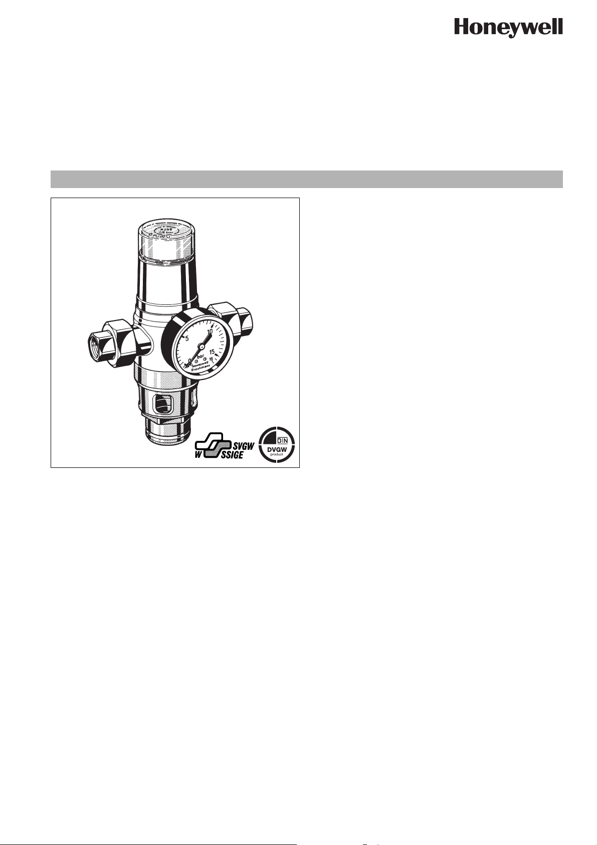
Mechanical disconnector with union connectors direct actuated
GA type according to EN1717 / type 1 according to DIN1988 part 4
Product specification sheet
Patent-No. DE PS 2751468
Construction
The mechanical disconnectors comprises:
• Housing with pressure gauge
• Outlet check valve
• Threaded union connectors
• Spring bonnet
• Discharge connection
• Valve insert with spring
• Spindle guide with double O-ring seal
Materials
• Red bronze housing
• Brass union nuts
• Red bronze threaded union connectors (brass for 2")
• High grade synthetic material valve disc
• High grade corrosion resistant synthetic material for other
internal parts
• High quality synthetic material discharge connection
• High quality synthetic material spring bonnet
• NBR seals
• Stainless steel valve stem and spring
EN0H-1205GE23 R0206 y Subject to change without notice
• High-quality synthetic material check valves
Application
Mechanical disconnectors of this type are suitable for the protection of drinking water systems as required by EN 1717 "The technical regulation of drinking water systems" and correspond to
DIN1988 part 4 type 1 construction.
Their purpose is to protect systems against back pressure, back
flow and back syphonage of non-potable water into the public
water supply network.
Mechanical disconnectors can be used to provide protection up
to and including liquid category 3 (slightly toxic substances).
Mechanical disconnectors therefore offer better protection than
check valves.
Special Features
• DIN/DVGW and SVGW approvals in all connection sizes
• Low pressure loss and high flow rate
• Optimal protection of the drinking water supply system
• Enhanced protection against back pressure, back flow and
back syphonage into the water supply network
• Shutoff position visually indicated on the spring bonnet
• Compact construction
• Standardised discharge connection
• Meets KTW recommendations for potable water
Range of Application
Medium Cold water
Max. inlet pressure 16.0 bar
Technical Data
Installation position Horizontal with spring bonnet upwards
Max. operating
temperature
Opening pressure 0.5, 1.0, 1.5 or 2.0 bar as required
Minimum inlet pressure
Connection size
40°C
= opening pressure + 1.0 bar
1
/2“ - 2“
www.honeywell.com 25
Page 2

R295 Mechanical disconnector with union connectors direct actuated
Method of Operation
GA-type mechanical disconnectors are safety valves that remain
in the flow position and change to the shutoff position only when
the inlet pressure falls below the design opening pressure.
The inlet pressure operates on the annular surface of the valve piston and pushes it against the force of the spring bringing the piston to the open position. If the supply pressure falls below the
opening pressure needed to overcome the spring force (for example because of a broken pipe or during service work by the
supply undertaking) then the integral spring pushes the valve into
the closed position.
Options
R295-... A = With internal threaded union connectors,
R295-... B = With internal threaded union connectors,
R295-... C = With internal threaded union connectors,
R295-... D = With internal threaded union connectors,
0.5 bar opening pressure
1.0 bar opening pressure
1.5 bar opening pressure
2.0 bar opening pressure
Connection size
Connection size R
1
/2"
3
/4"1"1
1
/4"1
1
/2"2"
Weight approx. kg 1.4 1.6 1.8 4.3 4.9 5.3
Dimensions mm
L 151 153 159 216 228 241
l 105 105 105 150 160 165
H 105 107 107 162 161 154
l 124 122 122 157 158 165
3
Nominal flow rate m
/h
at ∆p = 0.3 bar 2.5 3.3 4.5 7 10 15
-value 4.5 6 8 13 18 27
k
vs
ξ value 4 7 10 13 12.5 14
Opening pressure bar 0.5, 1.0, 1.5, oder 2.0 as required
DIN/DVGW Approval No. NW - 6301 AT 2319
Accessories
M07M Pressure gauge
Housing diameter 63 mm, rear connection thread
1
/4". Ranges: 0 - 4, 0 - 10, 0 - 16 or 0 - 25 bar. Plea-
G
se indicate upper value of pressure range when ordering
ZT295A Soldered union connectors (pack of 2)
Available for diameters from 15 - 54 mm
ZT295A
26 www.honeywell.com
M07M
EN0H-1205GE23 R0206 y Subject to change without notice
Page 3

Installation Example
R295 Mechanical disconnector with union connectors direct actuated
Installation Guidelines
• Install shutoff valves
• Install in horizontal pipework with spring bonnet directed upwards
o This orientation ensures optimum performance
• Ensure good access
o Pressure gauge can be read off easily
o Simplifies maintenance and inspection
• No further unprotected mains water supply may be connected downstream of the mechanical disconnector
• The mechanical disconnector must not be fitted in any areas
or ducts where poisonous gases or vapours may be present
or where flooding can occur
Flow Diagram
Typical Applications
Mechanical disconnectors of this type are suitable for supplies to
buildings
Within the scope of their specification can also be used for commercial and industrial applications.
The following are some typical applications:
• Softening and deacidification plants without DVGW approval
• Garden tap connections
• Soda machines
• Boilers and automatic pressure fermentation equipment
• Heating system filling assemblies without DVGW approval,
water without inhibitors
• Air conditioners
EN0H-1205GE23 R0206 y Subject to change without notice
www.honeywell.com 27
Page 4

R295 Mechanical disconnector with union connectors direct actuated
Spare Parts
Mechanical disconnector R295
No. Description Dimension Part No.
c Valve insert complete
0.5 bar
1.0 bar
1.5 bar
2.0 bar
d Seal ring set
e Hexagon-plug all S06M-1/4
with O-ring R
(5 pcs.)
f Union seal washer
g Inlet check valve
h Drain connection
complete 1
1
/2" - 1“ R295A-3/4A
1
1
/4" - 2“ R295A-11/4A
1
/2" - 1“ R295A-3/4B
1
/4" - 2“ R295A-11/4B
1
1
/2" - 1“ R295A-3/4C
1
/4" - 2“ R295A-11/4C
1
1
/2" - 1“ R295A-3/4D
1
/4" - 2“ R295A-11/4D
1
1
/2" - 1“ 0901055
1
/4" - 2“ 0901056
1
1
/4"
1
/2" 5351200
3
/4" 5351300
1" 5166300
1
/4" 5162900
1
1
1
/2" 5163000
2" 5163100
1
/2" RV282E-3/4A
3
/4"RV282E-1A
1" RV282E-1A
11/4" RV276-11/4
1
/2" RV276-11/2
1
2" RV276-2
1
/2" - 1“ 0901340
1
/4" - 2“ 0901341
Automation and Control Solutions
Honeywell GmbH
Hardhofweg
D-74821 Mosbach
Phone: (49) 6261 810
Fax: (49) 6261 81309
http://europe.hbc.honeywell.com
www.honeywell.com
Manufactured for and on behalf of the
Environmental and Combustion Controls Division
of Honeywell Technologies Sàrl, Ecublens, Route
du Bois 37, Switzerland by its Authorised Representative Honeywell GmbH
EN0H-1205GE23 R0206
Subject to change
© 2006 Honeywell GmbH
 Loading...