

Honeywell QX, QXe, SX Installation Instruction
QX, SX and QXe Recorders - Installation Instruction
Alarm Relay and Digital Input/Output cards
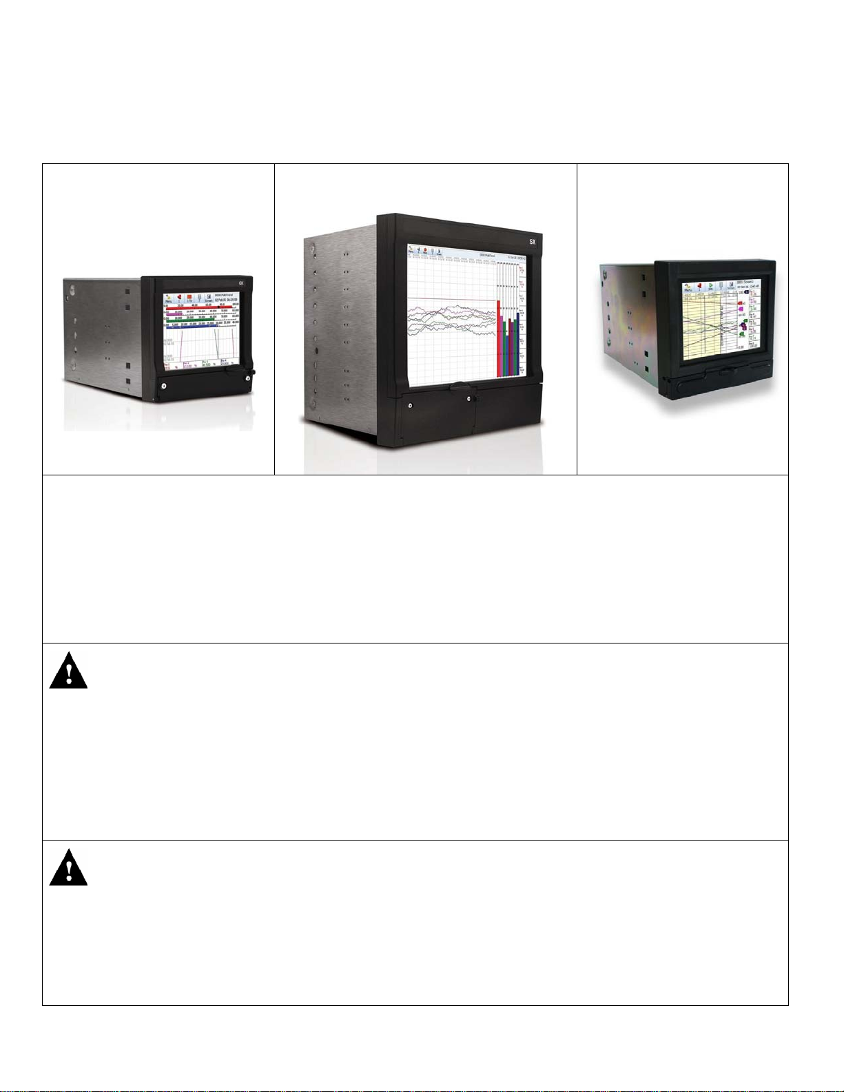
QX Recorder
SX Recorder
QXe Recorder
This Installation Instruction sheet is intended as a guide for replacing or installing hardware and for setting up
functionality in the recorder. Refer to the User manual for detailed operational requirements.
The QX, SX and QXe recorders are designed for ease of assembly with minimal disturbance to the rest of the unit. If
unsure, please return the unit to your supplier for repair or upgrade.
Removing the case and opening the back of the recorder should only be performed under the followin g circumstances:
When an item of hardware requires individual replacement.
When an item of hardware is to be retrospectively fitted.
In all other instances it is recommended that the complete unit be returned to an authorised agent or service centre.
For Agency Approved recorders the product needs to be upgraded or repaired b y an Authorized Repair facility
WARNING
HAZARDOUS VOLTAGES
Disconnect all power to the recorder before removing the case and attempting an y maintenance procedures.
SAFETY TESTS
Upon completion of service procedures detailed in this manual two basic safety tests should be performed in order to
ensure continued safe operation of the instrument.
Earth Resistance; 25 VDC applied between case and protective earth, bonding resistance should be < 0.1 Ohm.
Insulation Resistance; 500Vdc applied between the earth terminal, and the live and neutral terminal shorted together,
insulation resistance to be >2.0 MOhm. (Mega Ohm, NOT milli Ohm)
Failure to comply with these instructions could result in death or serious injury
CAUTION
OBSERVE ANTI-STATIC PRECAUTIONS
Refer to BS EN61340-5-1: 2001. Basic specification. Protection of electrostatic sensitive devices.
Full anti-static precautions MUST be observed when in contact with the electronics of your recorder.
SAVE DATA, SETUPS AND LAYOUTS
Removal of PCBs and battery back-up will result in the loss of all non-volatile data.
Ensure all data and set-ups are saved.
Failure to comply with these instructions may result in product damage.
43-TV-33-57 iss.2 GLO Oct 06 UK 1
Before attempting to repair or upgrade a recorder, it is advisable to clear a sufficient work space so components such as
the front panel can be rested on the work surface without getting scratched or damaged.
If adding a new piece of hardware to your recorder please be aware that if you are running Trend Manager PC software
that the “Hardware Wizard” will require updating to accommodate the hardware changes.
Panel Mounting
The Alarm/Digital IO cards can be removed, replaced or added to the recorder without removing it from its mounting
panel. If you require the recorder to be removed from the panel, loosen the mounting clamp screws, slide the clamp
towards the rear of the recorder and remove the clamps and the recorder.
Removing the Rear Panel
Removal of the rear panel is necessary for replacement or fitting any of the PC cards.
To remove the rear panel of the recorder, loosen and remove the two screws (QX and QXe = M3 x 6, SX = M4 x 8) at
the top corners of the rear panel, taking care to retain both the shake-proof washer and the screw.
Inside the Unit
Refer to Figure 1 for the SX recorder, Figure 2 for the QX recorder and Figure 3 for the QXe recorder and their
respective tables for the correct slot position for the Alarm Relay and Digital IO cards.
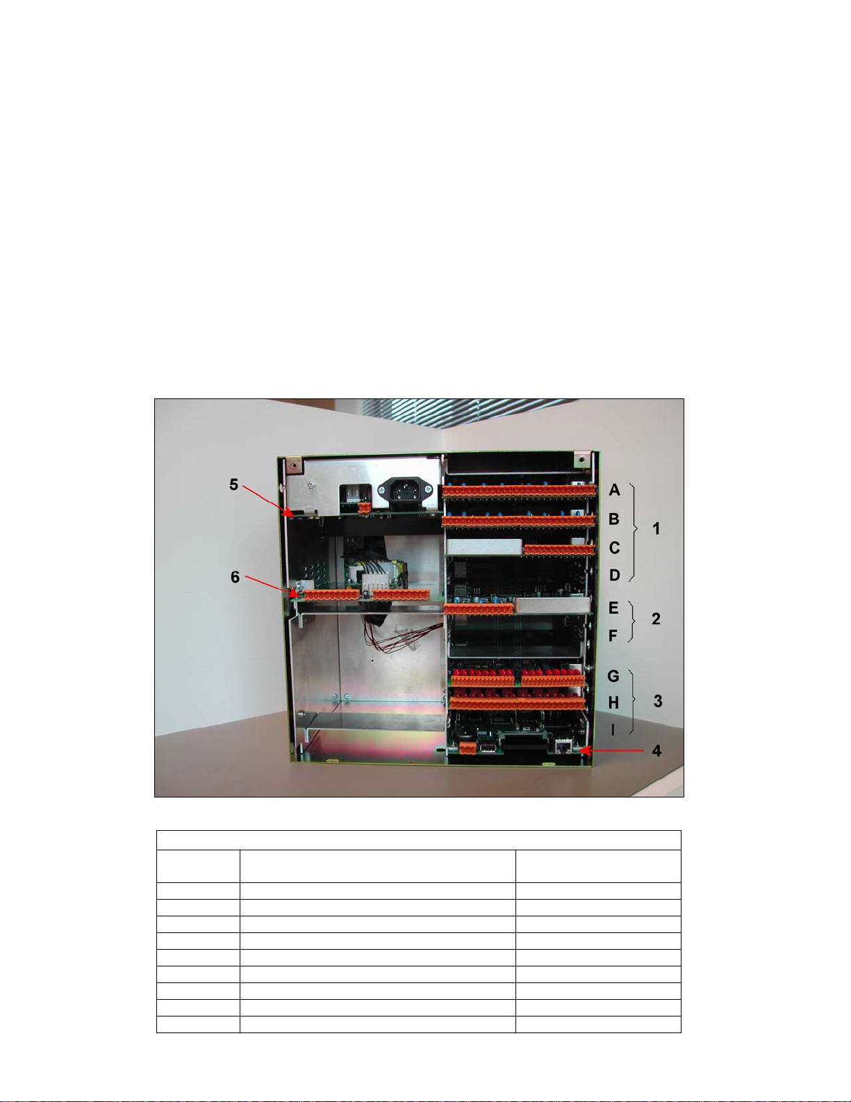
Figure 1
SX recorder
SX cards
Position
Shown
1A, 1B Analogue Input Card A, B, C, D, E, F
1C Pulse Input Card A, B, C, D, E, F
2E Analogue Output Card E, F
3G Digital IO Card G, H, I
3H Alarm Relay Card G, H, I
4 Processor Card
5 Power Supply Card
6 Transmitter Power Supply Card
Mother Board Not shown
Card Type Slot
43-TV-33-57 iss.2 GLO Oct 06 UK 2
 Loading...