

MA
MD
MS
Application
Solenoid valves series M are used in general refrigeration
and for original equipment to cut off/activate the refrigerant
flow in a refrigerating plant.
The solenoid valves can be installed in the liquid line, hot gas
line and suction line of a refrigerating unit.
Materials
Body
Seal material
Connection tubes
Coil
brass, stainless steel
PTFE
solder: copper
flare: brass
copper, steel, Crastin
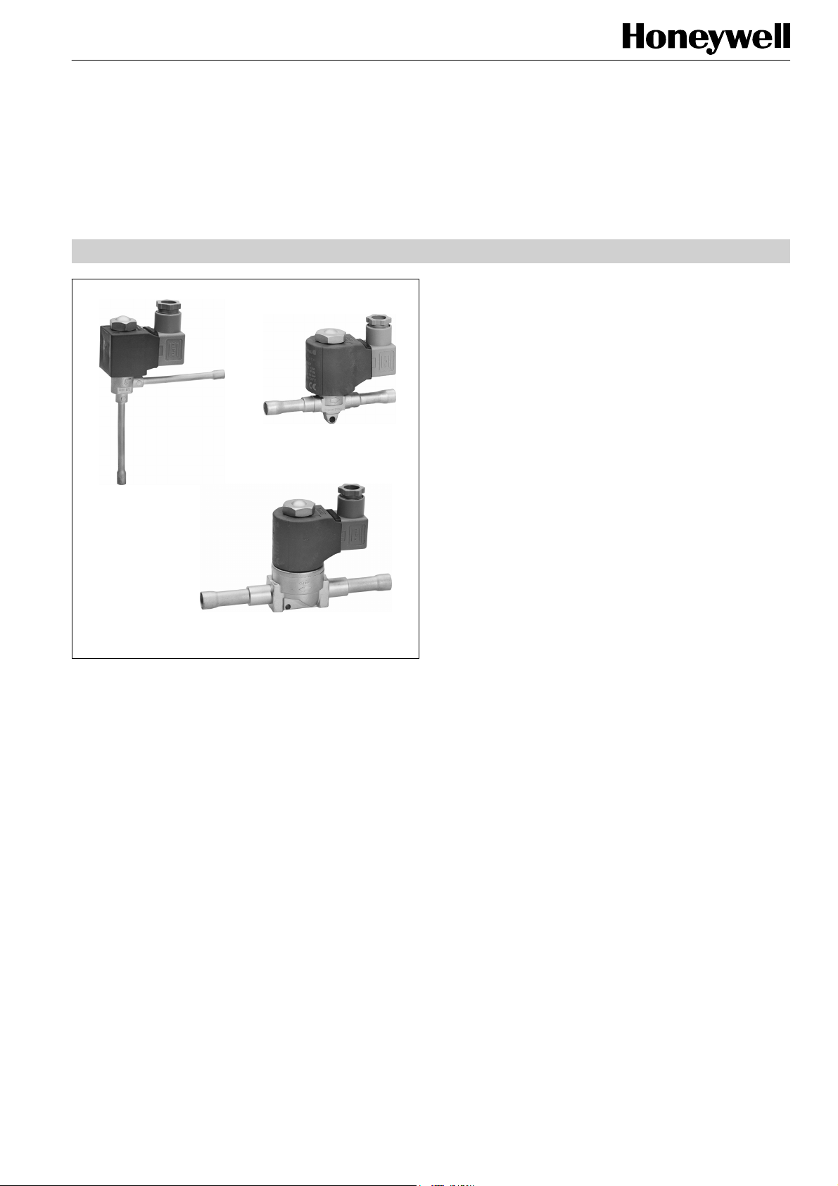
Series M
SOLENOID VALVES
NORMALLY CLOSED
PRODUCT DATA
Features
• MA: direct operated, angle construction
• MD: direct operated, two way construction
• MS: pilot operated, two way construction
• Normally closed
• Hermetic construction
• Low pressure drop
• High performance
• Direct operated: no minimum pressure differential
required to open the valve
• Pilot operated: minimum pressure differential of
0.05 bar required to open the valve
• Solder and flare connections
• Coils for AC and DC
• Refrigerants: all CFC, HCFC, HFC,
not for ammonia
Specification
Nominal capacity
Maximum pressure PS
Maximum test pressure PF
Min. pressure differential
Max. pressure differential
Max. opening pressure
differential MOPD
Max. medium temperature
Min. medium temperature
Max. ambient temperature
Min. ambient temperature
Number of operating cycles
Standard coil voltages
Voltage tolerance
see tables on page 2
35 bar(a)
50 bar(a)
MA, MD: 0 bar
MS: 0.05 bar
MS: 2 bar
AC-coil: MA, MD: 25 bar
MS: 30 bar
DC-coil: MA, MD: 21bar
MS: 21 bar
125 °C
-45 °C
80 °C
-40 °C
> 1,5 million
AC: 230V, 110V, 24V
DC: 230V, 24V
further voltages on request
AC: ±10%
DC: +10%, -5%
Copyright © 2009 Honeywell GmbH • Subject to change without notice EN0H-1917GE23 R0709

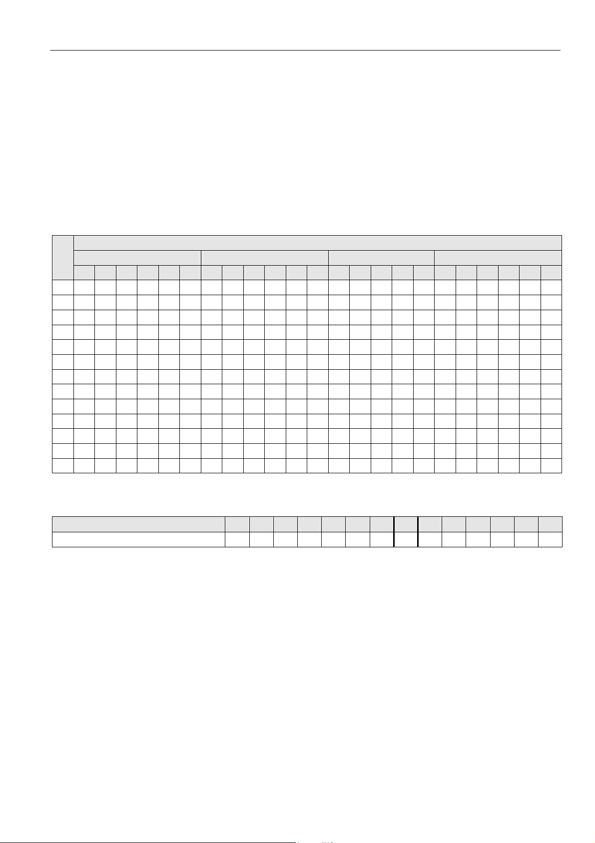
SERIES M
Nominal Capacity QN (kW)
Type
MA 062 0.17 5.21 5.62 5.39 3.87 1.14 1.47 1.45 1.29 - - - -
MD 062 0.17 5.21 5.62 5.39 3.87 1.14 1.47 1.45 1.29 - - - -
MD 102 0.22 6.74 7.27 6.98 5.01 1.48 1.90 1.88 1.67 - - - -
MD 103 0.23 7.05 7.61 7.29 5.24 1.54 1.99 1.96 1.75 - - - -
MS 103 0.9 27.6 29.8 28.5 20.5 6.04 7.78 7.67 6.83 1.54 2.06 1.92 1.80
MS 104 0.9 27.6 29.8 28.5 20.5 6.04 7.78 7.67 6,83 1.54 2.06 1.92 1.80
MS 124 1.6 49.0 52.9 50.7 36.4 10.7 13.8 13.6 12.1 2.74 3.66 3.42 3.19
MS 125 1.6 49.0 52.9 50.7 36.4 10.7 13.8 13.6 12.1 2.74 3.66 3.42 3.19
MS 165 2 61.3 66.1 63.4 45.5 13.4 17.3 17.1 15.2 3.42 4.57 4.27 3.99
MS 167 2 61.3 66.1 63.4 45.5 13.4 17.3 17.1 15.2 3.42 4.57 4.27 3.99
MS 227 4 123 132 127 91.1 26.8 34.6 34.1 30.4 6.85 9.14 8.54 7.98
The nominal capacity QN is based on the following conditions
Medium
Liquid -10 25 1 - 0.4
Hot gas -10 25 1 25 °C 1
Suction gas -10 25 1 - 0.15
Valve selection for other operating conditions see the following tables or consult the Honeywell software
kv-value
(m3/h)
Evaporating
temperature
R134a R22 R407C
t0 (°C) tc (°C)
Liquid Hot gas Suction gas
R404A
R507A
Direct operated
Pilot operated
Condensing
temperature
R134a R22 R407C
Subcooling
Δtc2u (K)
R404A
R507A
temperature
R134a R22 R407C
Hot gas
tH (°C)
Pressure loss
across valve
Δp (bar)
R404A
R507A
EN0H-1917GE23 R0709 2 Honeywell GmbH • Subject to change without notice
SERIES M
Valve size calculation for the liquid line
Refrigeration capacity Q0, multiplied with correcting factor fTF,
multiplied with correcting factor f
nominal capacity Q
N.
ΔPF results in the required
QN = Q0 x fTF x fΔPF
QN nominal capacity (according to table on page 2)
Q
0 refrigeration capacity
TF correcting factor for evaporating and liquid
f
temperature
f
ΔPF correcting factor for pressure loss across the valve
Correcting factor fTF for the change of capacity according to the operating temperatures
tL*
(°C)
+10 ±0 -10 -20 -30 -40 +10 ±0 -10 -20 -30 -40 +10 ±0 -10 -20 -30 +10 ±0 -10 -20 -30 -40
0 - - 0.80 0.83 0.85 0.88 - - 0.82 0.83 0.85 0.88 - - 0.80 0.80 0.80 - - 0.73 0.76 0.79 0.83
+5 - - 0.83 0.86 0.89 0.93 - - 0.85 0.87 0.89 0.91 - 0.80 0.80 0.80 0.90 - - 0.77 0.8 0.84 0.88
+10 - 0.84 0.87 0.91 0.94 0.97 - 0.86 0.88 0.90 0.92 0.95 - 0.80 0.90 0.90 0.90 - 0.79 0.82 0.85 0.89 0.94
+15 - 0.88 0.91 0.94 0.98 1.02 - 0.90 0.92 0.94 0.96 0.99 0.90 0.90 0.90 0.90 1.00 - 0.84 0.87 0.91 0.95 1.00
+20 0.89 0.92 0.95 0.99 1.03 1.08 0.92 0.94 0.96 0.98 1.00 1.03 0.90 0.90 0.90 1.00 1.00 0.86 0.89 0.93 0.97 1.02 1.08
+25 0.94 0.96 1.00 1.05 1.09 1.14 0.96 0.98 1.00 1.03 1.05 1.09 0.90 1.00 1.00 1.00 1.10 0.92 0.96 1.05 1.05 1.11 1.18
+30 0.99 1.02 1.06 1.12 1.16 1.22 1.01 1.02 1.05 1.08 1.10 1.14 1.00 1.00 1.00 1.10 1.20 0.99 1.03 1.08 1.14 1.21 1.29
+35 1.04 1.08 1.12 1.18 1.24 1.30 1.05 1.07 1.10 1.13 1.16 1.20 1.10 1.10 1.10 1.20 1.20 1.08 1.13 1.19 1.26 1.34 1.44
+40 1.10 1.14 1.19 1.26 1.32 1.39 1.10 1.12 1.15 1.19 1.22 1.26 1.10 1.20 1.20 1.30 1.30 1.18 1.24 1.32 1.40 1.50 1.63
+45 1.18 1.22 1.28 1.35 1.42 1.50 1.17 1.19 1.22 1.26 1.29 1.34 1.20 1.30 1.30 1.40 1.40 1.32 1.39 1.48 1.59 1.72 1.88
+50 1.25 1.24 1.37 1.45 1.53 1.62 1.23 1.26 1.29 1.33 1.37 1.42 1.30 1.40 1.40 1.50 1.60 1.50 1.59 1.7 1.85 2.02 2.23
+55 1.35 1.41 1.48 1.58 1.67 1.78 1.30 1.33 1.37 1.42 1.46 1.52 1.40 1.50 1.60 1.70 1.80 1.74 1.87 2.02 2.22 2.47 2.79
+60 1.46 1.55 1.61 1.73 1.84 1.97 1.38 1.41 1.46 1.51 1.56 1.63 - - - - - - - - - - -
* Temperature of liquid refrigerant at valve inlet.
Correcting factor f
Pressure loss across valve Δp (bar)
Correcting factor fΔPF
R134a R22 R407C R404A, R507A
ΔPF for the change of capacity according to the chosen pressure loss across the valve
Evaporating temperature t0 (°C)
0.05 0.10 0.15 0.20 0.25 0.30 0.35 0.40 0.45 0.50 0.55 0.60 0.65
2.83 2.00 1.63 1.41 1.26 1.15 1.07 1.00 0.94 0.89 0.85 0.82 0.78 0.76
0.70
Honeywell GmbH • Subject to change without notice 3 EN0H-1917GE23 R0709
 Loading...